EP1790541A2 - Systems and methods for detecting obstructions in a camera field of view - Google Patents
Systems and methods for detecting obstructions in a camera field of view Download PDFInfo
- Publication number
- EP1790541A2 EP1790541A2 EP06124640A EP06124640A EP1790541A2 EP 1790541 A2 EP1790541 A2 EP 1790541A2 EP 06124640 A EP06124640 A EP 06124640A EP 06124640 A EP06124640 A EP 06124640A EP 1790541 A2 EP1790541 A2 EP 1790541A2
- Authority
- EP
- European Patent Office
- Prior art keywords
- obstruction
- camera
- window
- primary
- image
- Prior art date
- Legal status (The legal status is an assumption and is not a legal conclusion. Google has not performed a legal analysis and makes no representation as to the accuracy of the status listed.)
- Withdrawn
Links
- 238000000034 method Methods 0.000 title claims abstract description 48
- 230000008569 process Effects 0.000 claims abstract description 7
- 239000000779 smoke Substances 0.000 claims description 30
- 238000012545 processing Methods 0.000 claims description 20
- 230000003213 activating effect Effects 0.000 claims description 19
- 230000006866 deterioration Effects 0.000 claims description 13
- 241000238631 Hexapoda Species 0.000 claims description 10
- 238000012706 support-vector machine Methods 0.000 claims description 10
- 239000000428 dust Substances 0.000 claims description 9
- 230000004913 activation Effects 0.000 claims description 8
- 239000012530 fluid Substances 0.000 claims description 8
- 230000007246 mechanism Effects 0.000 claims description 7
- 210000003608 fece Anatomy 0.000 claims description 6
- 230000005494 condensation Effects 0.000 claims description 5
- 238000009833 condensation Methods 0.000 claims description 5
- 238000003708 edge detection Methods 0.000 claims description 5
- 238000004140 cleaning Methods 0.000 claims description 4
- 238000005507 spraying Methods 0.000 claims description 3
- 230000001360 synchronised effect Effects 0.000 claims description 3
- 230000000977 initiatory effect Effects 0.000 claims 1
- 239000003897 fog Substances 0.000 description 17
- 238000001514 detection method Methods 0.000 description 12
- 230000009471 action Effects 0.000 description 9
- 238000004458 analytical method Methods 0.000 description 7
- 238000010586 diagram Methods 0.000 description 6
- 230000003287 optical effect Effects 0.000 description 6
- 239000000126 substance Substances 0.000 description 6
- 238000012360 testing method Methods 0.000 description 6
- 230000006735 deficit Effects 0.000 description 5
- 230000006870 function Effects 0.000 description 5
- 241000533950 Leucojum Species 0.000 description 4
- 238000003384 imaging method Methods 0.000 description 4
- 239000003595 mist Substances 0.000 description 4
- 239000011521 glass Substances 0.000 description 3
- 239000002245 particle Substances 0.000 description 3
- 230000008901 benefit Effects 0.000 description 2
- 230000001419 dependent effect Effects 0.000 description 2
- 238000010191 image analysis Methods 0.000 description 2
- 230000004044 response Effects 0.000 description 2
- 230000002238 attenuated effect Effects 0.000 description 1
- 230000000903 blocking effect Effects 0.000 description 1
- 230000008859 change Effects 0.000 description 1
- 238000010276 construction Methods 0.000 description 1
- 238000005286 illumination Methods 0.000 description 1
- 230000001771 impaired effect Effects 0.000 description 1
- 238000012986 modification Methods 0.000 description 1
- 230000004048 modification Effects 0.000 description 1
- 238000012544 monitoring process Methods 0.000 description 1
- 230000010287 polarization Effects 0.000 description 1
- 239000007787 solid Substances 0.000 description 1
- 230000002269 spontaneous effect Effects 0.000 description 1
- 238000010561 standard procedure Methods 0.000 description 1
- 239000013589 supplement Substances 0.000 description 1
- 230000007704 transition Effects 0.000 description 1
- 230000001960 triggered effect Effects 0.000 description 1
- 238000001429 visible spectrum Methods 0.000 description 1
- 230000000007 visual effect Effects 0.000 description 1
Images


Classifications
-
- G—PHYSICS
- G06—COMPUTING; CALCULATING OR COUNTING
- G06V—IMAGE OR VIDEO RECOGNITION OR UNDERSTANDING
- G06V20/00—Scenes; Scene-specific elements
- G06V20/50—Context or environment of the image
- G06V20/56—Context or environment of the image exterior to a vehicle by using sensors mounted on the vehicle
-
- B—PERFORMING OPERATIONS; TRANSPORTING
- B60—VEHICLES IN GENERAL
- B60Q—ARRANGEMENT OF SIGNALLING OR LIGHTING DEVICES, THE MOUNTING OR SUPPORTING THEREOF OR CIRCUITS THEREFOR, FOR VEHICLES IN GENERAL
- B60Q1/00—Arrangement of optical signalling or lighting devices, the mounting or supporting thereof or circuits therefor
- B60Q1/0017—Devices integrating an element dedicated to another function
- B60Q1/0023—Devices integrating an element dedicated to another function the element being a sensor, e.g. distance sensor, camera
-
- B—PERFORMING OPERATIONS; TRANSPORTING
- B60—VEHICLES IN GENERAL
- B60Q—ARRANGEMENT OF SIGNALLING OR LIGHTING DEVICES, THE MOUNTING OR SUPPORTING THEREOF OR CIRCUITS THEREFOR, FOR VEHICLES IN GENERAL
- B60Q1/00—Arrangement of optical signalling or lighting devices, the mounting or supporting thereof or circuits therefor
- B60Q1/02—Arrangement of optical signalling or lighting devices, the mounting or supporting thereof or circuits therefor the devices being primarily intended to illuminate the way ahead or to illuminate other areas of way or environments
- B60Q1/04—Arrangement of optical signalling or lighting devices, the mounting or supporting thereof or circuits therefor the devices being primarily intended to illuminate the way ahead or to illuminate other areas of way or environments the devices being headlights
- B60Q1/14—Arrangement of optical signalling or lighting devices, the mounting or supporting thereof or circuits therefor the devices being primarily intended to illuminate the way ahead or to illuminate other areas of way or environments the devices being headlights having dimming means
- B60Q1/1415—Dimming circuits
- B60Q1/1423—Automatic dimming circuits, i.e. switching between high beam and low beam due to change of ambient light or light level in road traffic
-
- B—PERFORMING OPERATIONS; TRANSPORTING
- B60—VEHICLES IN GENERAL
- B60Q—ARRANGEMENT OF SIGNALLING OR LIGHTING DEVICES, THE MOUNTING OR SUPPORTING THEREOF OR CIRCUITS THEREFOR, FOR VEHICLES IN GENERAL
- B60Q1/00—Arrangement of optical signalling or lighting devices, the mounting or supporting thereof or circuits therefor
- B60Q1/02—Arrangement of optical signalling or lighting devices, the mounting or supporting thereof or circuits therefor the devices being primarily intended to illuminate the way ahead or to illuminate other areas of way or environments
- B60Q1/04—Arrangement of optical signalling or lighting devices, the mounting or supporting thereof or circuits therefor the devices being primarily intended to illuminate the way ahead or to illuminate other areas of way or environments the devices being headlights
- B60Q1/18—Arrangement of optical signalling or lighting devices, the mounting or supporting thereof or circuits therefor the devices being primarily intended to illuminate the way ahead or to illuminate other areas of way or environments the devices being headlights being additional front lights
- B60Q1/20—Fog lights
-
- B—PERFORMING OPERATIONS; TRANSPORTING
- B60—VEHICLES IN GENERAL
- B60R—VEHICLES, VEHICLE FITTINGS, OR VEHICLE PARTS, NOT OTHERWISE PROVIDED FOR
- B60R11/00—Arrangements for holding or mounting articles, not otherwise provided for
- B60R11/04—Mounting of cameras operative during drive; Arrangement of controls thereof relative to the vehicle
-
- B—PERFORMING OPERATIONS; TRANSPORTING
- B60—VEHICLES IN GENERAL
- B60S—SERVICING, CLEANING, REPAIRING, SUPPORTING, LIFTING, OR MANOEUVRING OF VEHICLES, NOT OTHERWISE PROVIDED FOR
- B60S1/00—Cleaning of vehicles
- B60S1/02—Cleaning windscreens, windows or optical devices
- B60S1/023—Cleaning windscreens, windows or optical devices including defroster or demisting means
-
- B—PERFORMING OPERATIONS; TRANSPORTING
- B60—VEHICLES IN GENERAL
- B60S—SERVICING, CLEANING, REPAIRING, SUPPORTING, LIFTING, OR MANOEUVRING OF VEHICLES, NOT OTHERWISE PROVIDED FOR
- B60S1/00—Cleaning of vehicles
- B60S1/02—Cleaning windscreens, windows or optical devices
- B60S1/04—Wipers or the like, e.g. scrapers
- B60S1/06—Wipers or the like, e.g. scrapers characterised by the drive
- B60S1/08—Wipers or the like, e.g. scrapers characterised by the drive electrically driven
- B60S1/0818—Wipers or the like, e.g. scrapers characterised by the drive electrically driven including control systems responsive to external conditions, e.g. by detection of moisture, dirt or the like
- B60S1/0822—Wipers or the like, e.g. scrapers characterised by the drive electrically driven including control systems responsive to external conditions, e.g. by detection of moisture, dirt or the like characterized by the arrangement or type of detection means
- B60S1/0833—Optical rain sensor
- B60S1/0844—Optical rain sensor including a camera
-
- H—ELECTRICITY
- H04—ELECTRIC COMMUNICATION TECHNIQUE
- H04N—PICTORIAL COMMUNICATION, e.g. TELEVISION
- H04N7/00—Television systems
- H04N7/18—Closed-circuit television [CCTV] systems, i.e. systems in which the video signal is not broadcast
- H04N7/181—Closed-circuit television [CCTV] systems, i.e. systems in which the video signal is not broadcast for receiving images from a plurality of remote sources
-
- B—PERFORMING OPERATIONS; TRANSPORTING
- B60—VEHICLES IN GENERAL
- B60Q—ARRANGEMENT OF SIGNALLING OR LIGHTING DEVICES, THE MOUNTING OR SUPPORTING THEREOF OR CIRCUITS THEREFOR, FOR VEHICLES IN GENERAL
- B60Q2300/00—Indexing codes for automatically adjustable headlamps or automatically dimmable headlamps
- B60Q2300/10—Indexing codes relating to particular vehicle conditions
- B60Q2300/14—Other vehicle conditions
- B60Q2300/146—Abnormalities, e.g. fail-safe
-
- B—PERFORMING OPERATIONS; TRANSPORTING
- B60—VEHICLES IN GENERAL
- B60Q—ARRANGEMENT OF SIGNALLING OR LIGHTING DEVICES, THE MOUNTING OR SUPPORTING THEREOF OR CIRCUITS THEREFOR, FOR VEHICLES IN GENERAL
- B60Q2300/00—Indexing codes for automatically adjustable headlamps or automatically dimmable headlamps
- B60Q2300/30—Indexing codes relating to the vehicle environment
- B60Q2300/31—Atmospheric conditions
- B60Q2300/312—Adverse weather
-
- B—PERFORMING OPERATIONS; TRANSPORTING
- B60—VEHICLES IN GENERAL
- B60Q—ARRANGEMENT OF SIGNALLING OR LIGHTING DEVICES, THE MOUNTING OR SUPPORTING THEREOF OR CIRCUITS THEREFOR, FOR VEHICLES IN GENERAL
- B60Q2300/00—Indexing codes for automatically adjustable headlamps or automatically dimmable headlamps
- B60Q2300/30—Indexing codes relating to the vehicle environment
- B60Q2300/31—Atmospheric conditions
- B60Q2300/314—Ambient light
-
- B—PERFORMING OPERATIONS; TRANSPORTING
- B60—VEHICLES IN GENERAL
- B60R—VEHICLES, VEHICLE FITTINGS, OR VEHICLE PARTS, NOT OTHERWISE PROVIDED FOR
- B60R2300/00—Details of viewing arrangements using cameras and displays, specially adapted for use in a vehicle
- B60R2300/30—Details of viewing arrangements using cameras and displays, specially adapted for use in a vehicle characterised by the type of image processing
-
- B—PERFORMING OPERATIONS; TRANSPORTING
- B60—VEHICLES IN GENERAL
- B60R—VEHICLES, VEHICLE FITTINGS, OR VEHICLE PARTS, NOT OTHERWISE PROVIDED FOR
- B60R2300/00—Details of viewing arrangements using cameras and displays, specially adapted for use in a vehicle
- B60R2300/80—Details of viewing arrangements using cameras and displays, specially adapted for use in a vehicle characterised by the intended use of the viewing arrangement
- B60R2300/8053—Details of viewing arrangements using cameras and displays, specially adapted for use in a vehicle characterised by the intended use of the viewing arrangement for bad weather conditions or night vision
-
- B—PERFORMING OPERATIONS; TRANSPORTING
- B60—VEHICLES IN GENERAL
- B60R—VEHICLES, VEHICLE FITTINGS, OR VEHICLE PARTS, NOT OTHERWISE PROVIDED FOR
- B60R2300/00—Details of viewing arrangements using cameras and displays, specially adapted for use in a vehicle
- B60R2300/80—Details of viewing arrangements using cameras and displays, specially adapted for use in a vehicle characterised by the intended use of the viewing arrangement
- B60R2300/8093—Details of viewing arrangements using cameras and displays, specially adapted for use in a vehicle characterised by the intended use of the viewing arrangement for obstacle warning
Definitions
- the present invention relates to detecting and classifying obstructions on the windshield of an automobile as part of a vehicle control system and more particularly the present invention detects and identifies obstructions on the windshield using a camera focused on the plane of the windshield.
- Cameras are often used to acquire one or more images while viewing through a transparent window such as of glass.
- a vehicle control system 80 as disclosed by Stein in US patent 7,113, 867 .
- a camera 32 is mounted inside a "host" vehicle 10 behind the windshield, and camera 32 views the environment through the windshield.
- System 80 includes camera 32 and a processor 60 that analyzes the images acquired by camera 32.
- System 80 is operative to detect lane markings in road 20, pedestrians, other vehicles or obstacles, road signs. Commonly, the windshield becomes less transparent due to rain, condensed moisture and/or dirt and image quality of the images produced by camera 32 may be impaired.
- US patent 6,392,218 discloses a method for analyzing optical images to detect moisture on a surface such as a windshield of an automobile using a sensor that is mounted on the windshield of the vehicle.
- An image such as that of the hood of the vehicle is processed and blurriness in the image is associated with moisture on the windshield.
- the sensor includes an optical image detector and a microprocessor with supporting control circuitry.
- the optical image detector acquires two-dimensional optical images from either the vehicle itself or an area surrounding the vehicle ( e.g. the hood, the road ahead of the vehicle).
- the acquired optical images are then delivered to the microprocessor, which analyzes the image to determine whether moisture (such as rain) exists on the windshield.
- the microprocessor circuitry can activate the windshield wipers.
- US patent 6,392,218 is directed towards only detection of rain or moisture on the windshield.
- US patent 5,923,027 discloses a method of detecting moisture on a surface of a windshield using a sensor in conjunction with an infrared LED. Edges of moisture (i.e. rain) are detected by the sensor. The LED is used to check for fog on the windshield based upon the manner in which light is reflected. All objects detected by the sensor, including bugs, dirt, and headlamps from oncoming vehicles which create a bright spot in the image would initially be interpreted as moisture which then causes the windshield wipers to be activated. It is only after the wipers have been activated, if the object remains on the windshield, is the obstruction flagged as something other than rain. The spontaneous, random motion of the wipers creates an unnecessary driving distraction for the driver. Additionally, this system cannot differentiate between fog on the inside of the window and fog on the outside of the window.
- US patent 6,768,422 by Scofield, et al , discloses a method for determining if there is moisture on the surface of a windshield using a sensor in conjunction with a polarizing filter. The sensor determines if rain is present by using an edge detection algorithm. Fog is checked for by the polarization patterns created in the image.
- a vehicular vision system capable of detecting and distinguishing between different obstructions, e.g., between moisture and dirt on the windshield of a vehicle, as well as being able to distinguish whether the obstruction is on the inside of the window, e.g., fog, smoke or dust, or on the outside of the vehicle, e.g., fog, frost, snow.
- a vehicular vision system which is capable of differentiating between bright sots from on-coming vehicles and moisture on the window.
- primary camera refers to camera 32 mounted inside a vehicle and used in systems for detecting road lane markings, other vehicles, pedestrians, and/or road signs. Typically, primary camera 32 focuses on objects that are over five meters from the primary camera.
- secondary camera refers to a camera mounted inside a vehicle and used for detecting obstructions on the windshield, according to the present invention. Typically, the secondary camera focuses on objects that are less than 20cm from the camera.
- edge refers to a series of adjacent points in a digital image at which the intensity as measured at the points changes noticeably.
- An edge may be caused by different phenomena including: (a) discontinuities in depth, (b) discontinuities in surface orientation and (c) variations in scene illumination.
- gradient refers to a two dimensional vector with the components given by the derivatives in the horizontal and vertical directions, of the image intensity function at each image point. At each image point, the gradient vector points in the direction of largest possible intensity increase, and the length or magnitude of the gradient vector corresponds to the rate of change in that direction.
- window refers to a window either flat or curved installed on a vehicle which is at least partially transparent in a portion of the visible spectrum but not significantly translucent, opaque or hazy.
- window and “windshield” are used herein interchangeably and refers to the front window of the vehicle, the back window or a side window.
- windshield region refers to the area of a windshield of a vehicle, for example the windshield, subtended by the field of view of a camera situated inside the vehicle.
- classify and “identify” are used herein interchangeably in the context of classifying or identifying obstructions on a window.
- a system mounted on a vehicle for detecting an obstruction on an external surface of the windshield of the vehicle for detecting an obstruction on an external surface of the windshield of the vehicle.
- a primary camera is mounted inside the vehicle; the primary camera is configured to acquire images of the environment through the windshield.
- a secondary camera is focused on an external surface of the windshield, and operates to image the obstruction.
- a portion of the windshield, i.e. windshield region is subtended respectively by the field of view of the primary camera and the field of view of the secondary camera.
- a processor processes respective sequences of image data from both the primary camera and the secondary camera.
- edges are represented in the images by high spatial frequencies. If the windshield is sufficiently clean, no edges or only edges with insignificant gradient will show in the images of the secondary camera.
- a computerized system including a camera mounted on a vehicle for classifying at least one obstruction on a surface of a window of the vehicle, the system including: (a) a secondary camera mounted inside the vehicle, the secondary camera focusing on at least a portion of the surface of the window; and (b) a processor which processes a plurality of secondary images acquired by the secondary camera, and identifies the obstruction when present on the surface.
- the surface of the window can be selectably either the external surface of the window or the internal surface of the window.
- the system further includes a primary camera mounted inside the vehicle, the primary camera configured to acquire multiple primary images of the environment through the window. A region of the window is subtended by respective fields of view of the secondary camera and the primary camera.
- the processor processes respectively at least one of the primary images and at least one of the secondary images.
- the processor can use information extracted from the at least one primary image to selectably either enhance identifying the at least one obstruction or eliminating false identification of an obstruction.
- the obstruction may cause a deterioration of the quality in the primary image.
- the processor is capable of determining the deterioration of image quality in the primary images.
- the system may further include an activation mechanism operatively attached to the processor.
- the activation mechanism causes cleaning fluid to be sprayed on the window and windshield wipers to be activated when the processor identifies an obstruction, including dirt on the window while the surface is dry. When the obstruction includes dirt and moisture the processor activates the wiper.
- the processor When the processor identifies an obstruction, the processor initiates a task to remove the obstruction.
- the task is selected from the group of tasks consisting of: notification of the driver of the vehicle, disabling the system, activating wipers with or without cleaning fluid and activating defogging, turning on fog lights.
- the secondary camera may also focus on at least a portion of the internal surface of the window and identify an obstruction when present on internal surface.
- the secondary camera may perform tasks for the primary camera selected from the group of applications consisting of: ambient light sensing, gain control sensing.
- the system may further include a pulsing light source, capable of illuminating a region of the window.
- the secondary camera is synchronized with the pulsing of the light source and images the illuminated region.
- a method for classifying at least one obstruction on a surface of a window of a vehicle using a computerized system including a camera mounted on the vehicle for, the method including: (a) providing a secondary camera mounted inside the vehicle focusing on a surface of the window, and providing a secondary image of the surface; and (b) processing the secondary image thereby identifying an obstruction when present on the surface.
- the method may include edge detection to detect the obstruction.
- the method may further include providing a primary camera mounted inside the vehicle, configured to acquire multiple primary images of the environment through the window. A region of the window is subtended by respective fields of view of the secondary and the primary camera.
- the processing of a primary image yields detecting at least one obstruction and determining deterioration of image quality in the primary image, which is caused by the obstruction.
- Identifying an obstruction is also performed by processing a primary image which may selectably either enhance the identification of the obstruction or eliminating a false identification of an obstruction.
- the method may use the secondary camera ambient light sensing set the mode of the system to selectably either day mode, dusk mode or night mode and optionally, when determining the level of ambient light as being of dusk mode or night mode, turning on the headlights.
- the method can identify the obstruction is being one in the group consisting of: rain, dirt, mud, snow, frost, cracks, smoke, dust, condensation, smeared insects and bird droppings.
- the method initiates a task to remove the obstruction.
- the task is selected from the group of tasks consisting of: notification of the driver of the vehicle, disabling the system, activating windshield wipers, spraying fluid on windshield and activating defogging of a window.
- the processing of a primary image may include at least one other vehicular vision processing application selected from the group of applications consisting of: detecting lane markings in a road, detecting pedestrians, detecting vehicles, detecting obstacles, detecting road signs, lane keeping, headway keeping and headlights control.
- the application may be turned off, when an obstruction is identified.
- the identifying of the obstruction may include classifying the obstruction, using a Support Vector Machine (SVM) techniques or SVM with Radial Basis Function kernel techniques or any other technique know in the art.
- SVM Support Vector Machine
- the method may further include illuminating the window with a pulsing light source, whereas the secondary camera is operated synchronously with the pulsing light source.
- the present invention is a system mounted on a vehicle for detecting an obstruction on an external surface of a windshield of the vehicle.
- a primary camera typically used for a driver's warning system and/or for a vehicle control system, is mounted inside the vehicle behind the windshield. The primary camera is configured to acquire images of the environment through the windshield.
- a secondary camera is focused on a surface of the windshield. Due to the angle of the windshield a portion of the secondary camera is focused on the external surface of the windshield, and a portion of the secondary camera is focused on the interior of the window.
- the secondary camera operates to image the obstruction.
- a portion of the windshield, i.e. windshield region is subtended respectively by the field of view of the primary camera and the field of view of the secondary camera.
- the primary and secondary cameras work in conjunction with each other in order to assure that there are no obstructions blocking the primary camera, and to minimize unnecessary image processing of the secondary camera (e.g., in the case whereby the primary camera recognizes bright points of light from on-coming vehicles and notifies the secondary camera that the bright spot is indeed a light source and not moisture or some other obstruction on the windshield.)
- the principal intentions of the present invention include detecting and classifying different obstructing substances on the windshield.
- An aspect of the present invention is to distinguish between the various causes of image impairment since different causes of image impairment require a different response from the driver.
- dirt prompts the activation of the wipers with fluid and if the dirt persists, the driver is optionally prompted to manually clean the windshield
- fog prompts lighting of fog light
- the primary camera i.e. a driver's warning system and/or for a vehicle control.
- all obstructions on the windshield very similar in the images acquired by the primary camera, the primary camera being typically focused on objects outside the vehicle. Obstructions as viewed by the primary camera appear as blurred images, because the windshield and the obstructions on an external and internal surface of the windshield are significantly out of focus.
- the primary camera is preferably not used to determine the cause of the visibility impairment.
- FIG. 9a shows an example image of rain drops (502 and 504) on windshield 12 as viewed by the secondary camera.
- FIG. 12a shows an example image of dirt (530) on windshield 11 as viewed by the secondary camera.
- the dirt is imaged by the primary camera as a blurred patch 532, shown in FIG. 12b, while imaging a distant checkerboard-like target.
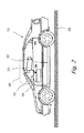
- FIG. 2 illustrates a vehicle having a camera obstruction detection and classification system, in accordance with an embodiment of the present invention.
- FIG. 2 depicts a host vehicle 10 that travels on a road surface 20, having a camera obstruction detection system 30, including: a primary camera 32; a secondary camera 33; and a processing unit 34.
- Primary camera 32 is mounted on host vehicle 10 viewing the environment through windshield 12 with a field of view typically of 30-50 degrees.
- Secondary camera 33 is mounted on host vehicle 10 and focuses on windshield 12 preferably over a windshield region subtended at least in part by the field of view of primary camera 32.
- FIG. 3 is a perspective view of an example of a camera obstruction detecting system 30, having a primary camera 32 and a secondary camera 33 situated side by side. Windshield region 43 of secondary camera 33 is at least overlapping windshield region 42 of primary camera 32.
- FIG. 4 is a perspective view that exemplifies a camera obstruction detection system 30 where primary camera 32 and secondary camera 33 are set one below the other. Windshield region 43 of secondary camera 33 is at least overlapping windshield region 42 of primary camera 32.
- the present invention is not limited to a side-by-side embodiment or a top-down embodiment.
- the system may be mounted on a front or rear windshield, as well as on a side window - or behind any glass surface, for example behind the glass enclosure of the headlamps or tail lamps of the vehicle.
- FIG. 5 is a close up view illustrating a camera obstruction detection system 30 where primary camera 32 and secondary camera 33 are situated one below the other, behind windshield 12.
- Windshield 12 has light obstructing substances 50 stuck onto windshield 12 external surfaces and blocks some of the light returning to primary camera 32.
- Secondary camera 33 is focused on an external surface of windshield 12 preferably in region subtended by the field of view of primary camera 32.
- system 30 is continuously monitoring windshield 12, analyzing secondary images. In some embodiments, the analysis of identifying an obstruction 50 is triggered by the primary vision processor 60.
- the optical axis secondary camera 33 is not completely perpendicular to windshield 12 surface. Due to the thickness of windshield 12 and the finite depth of field of secondary camera 33, in some parts of the image, typically the lower parts of the image, the inner surface of the windshield 12 is most in focus. Typically, in the upper parts of the image, the outer surface of windshield 12 is most in focus. Having the ability to also focus secondary camera 33, in parts of the secondary image, on the inner surface of windshield 12 allows system 30 to determine, in a case of fog, condensation or smoke residue (which the camera picks up as texture) whether it is outside the vehicle 10 or on the inner surface of windshield 12.
- Having the ability to also focus secondary camera 33, in parts of the secondary image, on the inner surface of windshield 12 allows system 30 to also detect other obstructions on the inner surface of windshield 12, such as accumulated smoke particles, fog or dust, and to determine where the obstruction is on the inside or outside of windshield 12.
- Other obstructions on the inner surface of windshield 12 such as accumulated smoke particles, fog or dust, and to determine where the obstruction is on the inside or outside of windshield 12.
- One such situation where it is necessary to check the inside of windshield 12 is when there is fog on windshield 12. The driver might have turned on the defogger to clear windshield 12, and yet the region in front of the camera might still not be cleared of the fog or frost.
- the system will be able to determine the proper corrective action, e.g. whether to signal for the heater, defogger or low visibility mode.
- FIG. 6 is a schematic flow diagram showing data and decision flows in system 30, in accordance with an embodiment of the present invention.
- primary camera 32 views the scene in front of primary camera 32 through windshield 12 as in prior art vision system 80. Often, light passing through windshield 12 is at least partially blocked, attenuated, scattered or absorbed by obstructions 50 on the external surface of windshield 12, before reaching primary camera 32.
- Primary camera 32 acquires images and transmits (step 132) the acquired images to primary vision processor 60 to be processed.
- Secondary camera 33 transmits (step 133) the acquired images to a high frequency presence decision module 134 for processing.
- Processor 34 detects substances 50 adhering to an external surface of windshield 12, and analyzes the image deterioration if any caused by detected light obstructing substances 50, on the images acquired by primary camera 32.
- the image deterioration caused by light obstructing substances 50 is considered negligible if the obstructed light has no measurable influence on the image quality from images from primary camera 32.
- the image deterioration when measured optionally causes system 30 to activate a low visibility mode, if the obstructed light reduces the performance of primary camera 32, but still executes part of the tasks.
- the image deterioration caused by light obstructing substances 50 can even cause primary camera 32 to stop function.
- edges are represented in the images by high spatial frequencies. If windshield 12 is sufficiently clean, edges with significant gradient do not show in the images acquired by secondary camera 33. If obstructions 50 are situated on a windshield region of windshield 12, then processing unit 34 determines the area on windshield 12 containing obstructions 50. The corresponding area in images acquired by primary camera 32 is also analyzed for high spatial frequencies. If the gradient of the edges detected is lower than some threshold, system 30 activates low visibility mode, having determined that obstructions 50 are present on a windshield region of windshield 12.
- secondary camera 33 transmits (step 133) the acquired images to a high frequency presence decision module 134 to be processed. If processing unit 34 detects in images acquired by secondary camera 33, in step 134, high spatial frequencies, representing edges, and in respective regions of respective images obtained by primary camera 32 no high spatial frequencies are observed in step 135, decision step 136 activates a low visibility mode, in step 137. Obstructions 50 detected by processor 34 in the images acquired by secondary camera 33, are classified in step 300 and actions are taken in step 301 according to the type of obstructions 50 detected and classified.
- FIG. 8 shows a schematic flow diagram outlining an algorithm 300 that exemplifies a method for classifying obstruction 50 types in a camera obstruction detecting system 30, according with an embodiment of the present invention.
- Obstructions 50 are detected by secondary camera 33, being focused on windshield 12.
- system 30 maps out false edges in the secondary image obtained in step 305, for example, a distant light source appears as a focused point of light in the primary image. It is well known from optics, that in a camera that is focused on the near distance (the secondary camera in the present invention), this point of light will appear as a disc with sharp edges. Such discs with sharp edges must be eliminated (step 306) from further analysis.
- the masked out secondary images are analyzed in step 310 for high frequencies representing sharp edges. If no edges were detected, images obtained in step 305 are analyzed in step 320 for blurry regions. If no blurry regions were detected in the primary image, algorithm 300 assumes windshield region 43 is clear.
- low visibility mode is turned off in step 325 and if the wipers were active the wipers are turned off in step 335. If blurry regions were detected in the primary image in step 320, fog, smoke (which is granular) or condensation situation or the like are assumed to persist; low visibility mode is activated in step 330 but if the wipers were activated, the wipers are turned off in step 335.
- step 310 system 30 proceeds into a classification procedure to classify 311 the detected obstruction 50. Images obtained in step 305 are further analyzed in step 312 to determined id the obstruction is a crack in windshield 12. If the obstruction is a crack, the crack edges are masked out from the secondary image, and system 30 proceeds to obtain the next image in step 305. If the classification fails in step 312, system 30 looks for objects with bright, dark, and grey spots in step 340. Objects with bright, dark and grey spots characterize rain drops. Rain may be stationary or seen as moving depending on whether the vehicle is stationary or moving. If one or more moving objects with both bright and dark spots are detected in step 340, rain is assumed and the wipers are activated in step 380.
- step 350 for detecting opaque objects such as thick mud. If in step 350 no opaque objects were detected, further analysis action is taken in step 355 for detecting semi-opaque objects such as frost or dust or smoke residue. If in step 350 no semi-opaque objects were detected, algorithm 300 assumes obstruction 50 represents an unknown obstruction 50. The unknown obstruction 50 might be a temporary obstruction, or a failing sensor, etc. Primary vision system 60 may be notified in step 357 and system 30 proceeds to obtain the next image in step 305.
- step 350 If in step 350 one or more opaque object was detected an attempt is made to remove the detected opaque object by activating in step 390 the mist for the wipers and in step 380 the wipers themselves. If in step 360 after a preset number of attempts to remove obstructions 50 is surpassed and obstructions 50 sustains, primary system processor 60 ( FIG. 6 ) is deactivated and the driver is preferably notified.
- step 355 frost is detected an attempt is made to remove the frost by activating in step 356 the defroster. If smoke residue is detected the driver may be notified to remove the smoke residue.
- FIG. 7 is a schematic flow diagram illustration of selecting day and night modes for a camera obstruction detecting system 30, in accordance with an embodiment of the present invention.
- system 30 determines if ambient lighting is that of day time or night time and sets system 30 parameters accordingly, in either step 151 or step 152.
- system 30 locates and analyzes the images obtained by secondary camera 33 for regions of high spatial frequency, classifies detected obstructions 50 and selects for each type of obstructions actions to be taken.
- the analysis for high spatial frequencies can be done by using Fourier transform, by comparing the gradient strength in images at various levels of image resolution and/or by any other method known in the art. If high frequencies are detected in step 310, corresponding regions in corresponding images obtained by primary camera 32 are also analyzed for high spatial frequencies. If at least one of the corresponding regions in corresponding images obtained by primary camera 32 lack high frequencies, low visibility analysis 300 proceeds.
- Secondary camera 33 is not performing time critical processing and thus, secondary camera 33 can be optionally used for other tasks, to supplement primary camera 32.
- secondary camera 33 can be used as an ambient light sensor or as a sensor for the gain control of primary camera 32.
- system 30 also includes a light source, for example a LED, mounted, for example, inside secondary camera 33 mount.
- a light source for example a LED
- the light source flashes instantaneously, at a low frequency rate, such that the pulsing does not interfere with other operations of primary camera 32.
- the light source illuminates windshield 12 and secondary camera 33, which is synchronized with the timing of the flashing, is imaging the lit windshield 12.
Landscapes
- Engineering & Computer Science (AREA)
- Mechanical Engineering (AREA)
- Multimedia (AREA)
- Automation & Control Theory (AREA)
- Signal Processing (AREA)
- Physics & Mathematics (AREA)
- General Physics & Mathematics (AREA)
- Theoretical Computer Science (AREA)
- Investigating Or Analysing Materials By Optical Means (AREA)
- Image Analysis (AREA)
Abstract
A system mounted on a vehicle for detecting an obstruction on a surface of a window of the vehicle, a primary camera (32) is mounted inside the vehicle (10) behind the window. The primary camera (32) is configured to acquire images of the environment through the window. A secondary camera (33) is focused on an external surface of the window, and operates to image the obstruction. A portion of the window, i.e. window region is subtended respectively by the field of view of the primary camera (32) and the field of view of the secondary camera (33). A processor processes respective sequences of image data from both the primary camera (32) and the secondary camera (33).
Description
- This application claims the benefit under 35 USC 119(e) from
US provisional application 60/738,991 filed November 23, 2005 - The present invention relates to detecting and classifying obstructions on the windshield of an automobile as part of a vehicle control system and more particularly the present invention detects and identifies obstructions on the windshield using a camera focused on the plane of the windshield.
- Cameras are often used to acquire one or more images while viewing through a transparent window such as of glass. One such application is illustrated in FIG. 1, a
vehicle control system 80 as disclosed by Stein inUS patent 7,113, 867 . Acamera 32 is mounted inside a "host"vehicle 10 behind the windshield, andcamera 32 views the environment through the windshield.System 80 includescamera 32 and aprocessor 60 that analyzes the images acquired bycamera 32.System 80 is operative to detect lane markings inroad 20, pedestrians, other vehicles or obstacles, road signs. Commonly, the windshield becomes less transparent due to rain, condensed moisture and/or dirt and image quality of the images produced bycamera 32 may be impaired. -
US patent 6,392,218 , by Kuehnle, discloses a method for analyzing optical images to detect moisture on a surface such as a windshield of an automobile using a sensor that is mounted on the windshield of the vehicle. An image such as that of the hood of the vehicle is processed and blurriness in the image is associated with moisture on the windshield. The sensor includes an optical image detector and a microprocessor with supporting control circuitry. The optical image detector acquires two-dimensional optical images from either the vehicle itself or an area surrounding the vehicle (e.g. the hood, the road ahead of the vehicle). The acquired optical images are then delivered to the microprocessor, which analyzes the image to determine whether moisture (such as rain) exists on the windshield. Upon detection of sufficient moisture on the vehicle, the microprocessor circuitry can activate the windshield wipers.US patent 6,392,218 is directed towards only detection of rain or moisture on the windshield. -
US patent 5,923,027 , by Stam et ai, discloses a method of detecting moisture on a surface of a windshield using a sensor in conjunction with an infrared LED. Edges of moisture (i.e. rain) are detected by the sensor. The LED is used to check for fog on the windshield based upon the manner in which light is reflected. All objects detected by the sensor, including bugs, dirt, and headlamps from oncoming vehicles which create a bright spot in the image would initially be interpreted as moisture which then causes the windshield wipers to be activated. It is only after the wipers have been activated, if the object remains on the windshield, is the obstruction flagged as something other than rain. The spontaneous, random motion of the wipers creates an unnecessary driving distraction for the driver. Additionally, this system cannot differentiate between fog on the inside of the window and fog on the outside of the window. -
US patent 6,768,422, by Scofield, et al , discloses a method for determining if there is moisture on the surface of a windshield using a sensor in conjunction with a polarizing filter. The sensor determines if rain is present by using an edge detection algorithm. Fog is checked for by the polarization patterns created in the image. - All of the above previously disclosed patents are limited by not being able to differentiate between various objects which might appear on a windshield of a vehicle - including, rain, dirt, dust, frost, bugs, cracks, and bird droppings. Additionally these systems are not able to distinguish between fog on the inside of the window and fog on the outside of the window.
- None of the above prior art systems provide a solution to bright spots of oncoming vehicles, being misinterpreted as moisture.
- Just as a driver of a vehicle responds differently to various obstruction on a windshield, e.g., turning on wipers, spraying the windows, enabling the defogger, etc, so to there is a need for and it would be advantageous to have a vehicular vision system capable of detecting and distinguishing between different obstructions, e.g., between moisture and dirt on the windshield of a vehicle, as well as being able to distinguish whether the obstruction is on the inside of the window, e.g., fog, smoke or dust, or on the outside of the vehicle, e.g., fog, frost, snow. And in order to minimize extraneous use of the wipers there is a need to for a vehicular vision system which is capable of differentiating between bright sots from on-coming vehicles and moisture on the window.
- The term "primary camera" as used herein refers to
camera 32 mounted inside a vehicle and used in systems for detecting road lane markings, other vehicles, pedestrians, and/or road signs. Typically,primary camera 32 focuses on objects that are over five meters from the primary camera. - The term "secondary camera" as used herein refers to a camera mounted inside a vehicle and used for detecting obstructions on the windshield, according to the present invention. Typically, the secondary camera focuses on objects that are less than 20cm from the camera.
- The term "edge" as used herein refers to a series of adjacent points in a digital image at which the intensity as measured at the points changes noticeably. An edge may be caused by different phenomena including: (a) discontinuities in depth, (b) discontinuities in surface orientation and (c) variations in scene illumination.
- The term "gradient" as used herein refers to a two dimensional vector with the components given by the derivatives in the horizontal and vertical directions, of the image intensity function at each image point. At each image point, the gradient vector points in the direction of largest possible intensity increase, and the length or magnitude of the gradient vector corresponds to the rate of change in that direction.
- The term "windshield" as used herein refers to a window either flat or curved installed on a vehicle which is at least partially transparent in a portion of the visible spectrum but not significantly translucent, opaque or hazy.
- The terms "window" and "windshield" are used herein interchangeably and refers to the front window of the vehicle, the back window or a side window.
- The term "windshield region" as used herein refers to the area of a windshield of a vehicle, for example the windshield, subtended by the field of view of a camera situated inside the vehicle.
- The terms "classify" and "identify" are used herein interchangeably in the context of classifying or identifying obstructions on a window.
- According to the teachings of the present invention there is provided a system mounted on a vehicle for detecting an obstruction on an external surface of the windshield of the vehicle. A primary camera is mounted inside the vehicle; the primary camera is configured to acquire images of the environment through the windshield. A secondary camera is focused on an external surface of the windshield, and operates to image the obstruction. A portion of the windshield, i.e. windshield region is subtended respectively by the field of view of the primary camera and the field of view of the secondary camera. A processor processes respective sequences of image data from both the primary camera and the secondary camera.
- In vision systems where the image analysis is at least partially based on edge detection, such edges are represented in the images by high spatial frequencies. If the windshield is sufficiently clean, no edges or only edges with insignificant gradient will show in the images of the secondary camera.
- According to the present invention there is provided a computerized system including a camera mounted on a vehicle for classifying at least one obstruction on a surface of a window of the vehicle, the system including: (a) a secondary camera mounted inside the vehicle, the secondary camera focusing on at least a portion of the surface of the window; and (b) a processor which processes a plurality of secondary images acquired by the secondary camera, and identifies the obstruction when present on the surface. The surface of the window can be selectably either the external surface of the window or the internal surface of the window.
- The system further includes a primary camera mounted inside the vehicle, the primary camera configured to acquire multiple primary images of the environment through the window. A region of the window is subtended by respective fields of view of the secondary camera and the primary camera. The processor processes respectively at least one of the primary images and at least one of the secondary images.
- The processor can use information extracted from the at least one primary image to selectably either enhance identifying the at least one obstruction or eliminating false identification of an obstruction.
- The obstruction may cause a deterioration of the quality in the primary image. The processor is capable of determining the deterioration of image quality in the primary images.
- The system may further include an activation mechanism operatively attached to the processor. The activation mechanism causes cleaning fluid to be sprayed on the window and windshield wipers to be activated when the processor identifies an obstruction, including dirt on the window while the surface is dry. When the obstruction includes dirt and moisture the processor activates the wiper.
- When the processor identifies an obstruction, the processor initiates a task to remove the obstruction. The task is selected from the group of tasks consisting of: notification of the driver of the vehicle, disabling the system, activating wipers with or without cleaning fluid and activating defogging, turning on fog lights.
- The secondary camera may also focus on at least a portion of the internal surface of the window and identify an obstruction when present on internal surface.
- The secondary camera may perform tasks for the primary camera selected from the group of applications consisting of: ambient light sensing, gain control sensing.
- The system may further include a pulsing light source, capable of illuminating a region of the window. The secondary camera is synchronized with the pulsing of the light source and images the illuminated region. According to the present invention there is provided a method for classifying at least one obstruction on a surface of a window of a vehicle, using a computerized system including a camera mounted on the vehicle for, the method including: (a) providing a secondary camera mounted inside the vehicle focusing on a surface of the window, and providing a secondary image of the surface; and (b) processing the secondary image thereby identifying an obstruction when present on the surface. The method may include edge detection to detect the obstruction.
- The method may further include providing a primary camera mounted inside the vehicle, configured to acquire multiple primary images of the environment through the window. A region of the window is subtended by respective fields of view of the secondary and the primary camera. The processing of a primary image yields detecting at least one obstruction and determining deterioration of image quality in the primary image, which is caused by the obstruction.
- Identifying an obstruction is also performed by processing a primary image which may selectably either enhance the identification of the obstruction or eliminating a false identification of an obstruction.
- The method may use the secondary camera ambient light sensing set the mode of the system to selectably either day mode, dusk mode or night mode and optionally, when determining the level of ambient light as being of dusk mode or night mode, turning on the headlights.
- The method can identify the obstruction is being one in the group consisting of: rain, dirt, mud, snow, frost, cracks, smoke, dust, condensation, smeared insects and bird droppings. Upon identifying an obstruction, the method initiates a task to remove the obstruction. The task is selected from the group of tasks consisting of: notification of the driver of the vehicle, disabling the system, activating windshield wipers, spraying fluid on windshield and activating defogging of a window.
- The processing of a primary image may include at least one other vehicular vision processing application selected from the group of applications consisting of: detecting lane markings in a road, detecting pedestrians, detecting vehicles, detecting obstacles, detecting road signs, lane keeping, headway keeping and headlights control. The application may be turned off, when an obstruction is identified.
- The identifying of the obstruction may include classifying the obstruction, using a Support Vector Machine (SVM) techniques or SVM with Radial Basis Function kernel techniques or any other technique know in the art.
- The method may further include illuminating the window with a pulsing light source, whereas the secondary camera is operated synchronously with the pulsing light source.
- These and other advantages of the present invention will become apparent upon reading the following detailed descriptions and studying the various figures of the drawings.
- The present invention will become fully understood from the detailed description given herein below and the accompanying drawings, which are given by way of illustration and example only and thus not limitative of the present invention, and wherein:
- FIG. 1 illustrates a prior art system installed in a vehicle having a primary camera, designated to detect road lane markings, pedestrians, other vehicles or obstacles, and/or road signs;
- FIG. 2 illustrates a vehicle having a camera obstruction detection and classification system, in accordance with an embodiment of the present invention;
- FIG. 3 is a perspective view that exemplifies a camera obstruction detecting and classifying system where the primary camera and the secondary camera are set side by side;
- FIG. 4 is a perspective view that exemplifies a camera obstruction detection system where the primary camera and the secondary camera are set one below the other;
- FIG. 5 is a close up side view illustrating a camera obstruction detection system where the primary camera and the secondary camera are set one below the other, behind the vehicle obstructed windshield;
- FIG. 6 is a schematic flow diagram showing the data and decision flow in a camera obstruction detecting system, in accordance with an embodiment of the present invention;
- FIG. 7 is a schematic flow diagram outlining an algorithm that exemplifies a method for classifying obstruction types in a camera obstruction detecting system, according with an embodiment of the present invention; and
- FIG. 8 is a schematic flow diagram illustration of selecting day and night modes for a camera obstruction detecting system, in accordance with an embodiment of the present invention.
- FIG. 9a shows an example image of rain drops on the windshield as viewed by the secondary camera of a camera obstruction detecting system, in accordance with an embodiment of the present invention.
- FIG. 9b shows the example of the rain drops on the windshield illustrated in FIG. 9a, as viewed by the primary camera of a camera obstruction detecting system, in accordance with an embodiment of the present invention.
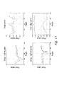
- FIGs. 10a, 10b and 10c illustrate a raindrop and its tri-points that are a distinctive feature of raindrops.
- FIG. 11 shows, by way of example, a series of graphs characterizing the tri-points that are a distinctive feature of raindrops.
- FIG. 12a shows an example image of an opaque obstruction on the windshield, as viewed by the secondary camera of a camera obstruction detecting system, in accordance with an embodiment of the present invention.
- FIG. 12b shows the example of the opaque obstruction on the windshield illustrated in FIG. 12a, as viewed by the primary camera of a camera obstruction detecting system, in accordance with an embodiment of the present invention.
- FIG. 13 shows, by way of example, the drop in image contrast of primary images, caused by a smeared/squashed insect.
- FIG. 14 shows, by way of example, the differences in typical edge profiles of a rain drop edge segment, light mud edge segment and thick mud edge segment.
- The present invention is a system mounted on a vehicle for detecting an obstruction on an external surface of a windshield of the vehicle. A primary camera typically used for a driver's warning system and/or for a vehicle control system, is mounted inside the vehicle behind the windshield. The primary camera is configured to acquire images of the environment through the windshield. A secondary camera is focused on a surface of the windshield. Due to the angle of the windshield a portion of the secondary camera is focused on the external surface of the windshield, and a portion of the secondary camera is focused on the interior of the window. The secondary camera operates to image the obstruction. A portion of the windshield, i.e. windshield region is subtended respectively by the field of view of the primary camera and the field of view of the secondary camera. The primary and secondary cameras work in conjunction with each other in order to assure that there are no obstructions blocking the primary camera, and to minimize unnecessary image processing of the secondary camera (e.g., in the case whereby the primary camera recognizes bright points of light from on-coming vehicles and notifies the secondary camera that the bright spot is indeed a light source and not moisture or some other obstruction on the windshield.)
- Before explaining embodiments of the invention in detail, it is to be understood that the invention is not limited in its application to the details of construction and the arrangement of the components set forth in the host description or illustrated in the drawings.
- Unless otherwise defined, all technical and scientific terms used herein have the same meaning as commonly understood by one of ordinary skill in the art of the invention belongs. The methods and examples provided herein are illustrative only and not intended to be limiting.
- By way of introduction, the principal intentions of the present invention include detecting and classifying different obstructing substances on the windshield.
- An aspect of the present invention is to distinguish between the various causes of image impairment since different causes of image impairment require a different response from the driver. In particular (a) rain drops and snow flakes prompt activation of the wipers, (b) dirt prompts the activation of the wipers with fluid and if the dirt persists, the driver is optionally prompted to manually clean the windshield, (c) smoke and dust particles collected on the inside of the windshield might require special service, (d) fog prompts lighting of fog light and (e) condensation prompts activating a defogger. Thus it is important to be able to distinguish between the different causes of image impairment. When an obstruction is detected, a low visibility signal may be generated indicating possible system unavailability due to image impairment.
- It is another aspect of the present invention to integrate the detection and identification of the obstructions on the windshield with the function of the primary camera, i.e. a driver's warning system and/or for a vehicle control. It should be noted that all obstructions on the windshield very similar in the images acquired by the primary camera, the primary camera being typically focused on objects outside the vehicle. Obstructions as viewed by the primary camera appear as blurred images, because the windshield and the obstructions on an external and internal surface of the windshield are significantly out of focus. Thus the primary camera is preferably not used to determine the cause of the visibility impairment. FIG. 9a shows an example image of rain drops (502 and 504) on
windshield 12 as viewed by the secondary camera. The rain drops are imaged by the primary camera as ablurred patch blurred patch 532, shown in FIG. 12b, while imaging a distant checkerboard-like target. - FIG. 2 illustrates a vehicle having a camera obstruction detection and classification system, in accordance with an embodiment of the present invention. FIG. 2 depicts a
host vehicle 10 that travels on aroad surface 20, having a cameraobstruction detection system 30, including: aprimary camera 32; asecondary camera 33; and aprocessing unit 34.Primary camera 32 is mounted onhost vehicle 10 viewing the environment throughwindshield 12 with a field of view typically of 30-50 degrees.Secondary camera 33 is mounted onhost vehicle 10 and focuses onwindshield 12 preferably over a windshield region subtended at least in part by the field of view ofprimary camera 32. - FIG. 3 is a perspective view of an example of a camera
obstruction detecting system 30, having aprimary camera 32 and asecondary camera 33 situated side by side.Windshield region 43 ofsecondary camera 33 is at least overlappingwindshield region 42 ofprimary camera 32. - FIG. 4 is a perspective view that exemplifies a camera
obstruction detection system 30 whereprimary camera 32 andsecondary camera 33 are set one below the other.Windshield region 43 ofsecondary camera 33 is at least overlappingwindshield region 42 ofprimary camera 32. - The present invention is not limited to a side-by-side embodiment or a top-down embodiment. The system may be mounted on a front or rear windshield, as well as on a side window - or behind any glass surface, for example behind the glass enclosure of the headlamps or tail lamps of the vehicle.
- FIG. 5 is a close up view illustrating a camera
obstruction detection system 30 whereprimary camera 32 andsecondary camera 33 are situated one below the other, behindwindshield 12.Windshield 12 haslight obstructing substances 50 stuck ontowindshield 12 external surfaces and blocks some of the light returning toprimary camera 32.Secondary camera 33 is focused on an external surface ofwindshield 12 preferably in region subtended by the field of view ofprimary camera 32. Typically,system 30 is continuously monitoringwindshield 12, analyzing secondary images. In some embodiments, the analysis of identifying anobstruction 50 is triggered by theprimary vision processor 60. - Often, the optical axis
secondary camera 33 is not completely perpendicular towindshield 12 surface. Due to the thickness ofwindshield 12 and the finite depth of field ofsecondary camera 33, in some parts of the image, typically the lower parts of the image, the inner surface of thewindshield 12 is most in focus. Typically, in the upper parts of the image, the outer surface ofwindshield 12 is most in focus. Having the ability to also focussecondary camera 33, in parts of the secondary image, on the inner surface ofwindshield 12 allowssystem 30 to determine, in a case of fog, condensation or smoke residue (which the camera picks up as texture) whether it is outside thevehicle 10 or on the inner surface ofwindshield 12. Having the ability to also focussecondary camera 33, in parts of the secondary image, on the inner surface ofwindshield 12 allowssystem 30 to also detect other obstructions on the inner surface ofwindshield 12, such as accumulated smoke particles, fog or dust, and to determine where the obstruction is on the inside or outside ofwindshield 12. One such situation where it is necessary to check the inside ofwindshield 12 is when there is fog onwindshield 12. The driver might have turned on the defogger toclear windshield 12, and yet the region in front of the camera might still not be cleared of the fog or frost. By checking if the fog is on the inside or outside ofwindshield 12, the system will be able to determine the proper corrective action, e.g. whether to signal for the heater, defogger or low visibility mode. - FIG. 6 is a schematic flow diagram showing data and decision flows in
system 30, in accordance with an embodiment of the present invention. In avision system 30 mounted onhost vehicle 10,primary camera 32 views the scene in front ofprimary camera 32 throughwindshield 12 as in priorart vision system 80. Often, light passing throughwindshield 12 is at least partially blocked, attenuated, scattered or absorbed byobstructions 50 on the external surface ofwindshield 12, before reachingprimary camera 32.Primary camera 32 acquires images and transmits (step 132) the acquired images toprimary vision processor 60 to be processed.Secondary camera 33 transmits (step 133) the acquired images to a high frequencypresence decision module 134 for processing. -
Processor 34 detectssubstances 50 adhering to an external surface ofwindshield 12, and analyzes the image deterioration if any caused by detectedlight obstructing substances 50, on the images acquired byprimary camera 32. The image deterioration caused by light obstructingsubstances 50 is considered negligible if the obstructed light has no measurable influence on the image quality from images fromprimary camera 32. The image deterioration when measured optionally causessystem 30 to activate a low visibility mode, if the obstructed light reduces the performance ofprimary camera 32, but still executes part of the tasks. The image deterioration caused by light obstructingsubstances 50 can even causeprimary camera 32 to stop function. - In vision systems, where the image analysis is at least partially based on edge detection, such edges are represented in the images by high spatial frequencies. If
windshield 12 is sufficiently clean, edges with significant gradient do not show in the images acquired bysecondary camera 33. Ifobstructions 50 are situated on a windshield region ofwindshield 12, then processingunit 34 determines the area onwindshield 12 containingobstructions 50. The corresponding area in images acquired byprimary camera 32 is also analyzed for high spatial frequencies. If the gradient of the edges detected is lower than some threshold,system 30 activates low visibility mode, having determined thatobstructions 50 are present on a windshield region ofwindshield 12. - Referring back to FIG. 6,
secondary camera 33 transmits (step 133) the acquired images to a high frequencypresence decision module 134 to be processed. If processingunit 34 detects in images acquired bysecondary camera 33, instep 134, high spatial frequencies, representing edges, and in respective regions of respective images obtained byprimary camera 32 no high spatial frequencies are observed instep 135,decision step 136 activates a low visibility mode, instep 137.Obstructions 50 detected byprocessor 34 in the images acquired bysecondary camera 33, are classified instep 300 and actions are taken instep 301 according to the type ofobstructions 50 detected and classified. - FIG. 8 shows a schematic flow diagram outlining an
algorithm 300 that exemplifies a method for classifyingobstruction 50 types in a cameraobstruction detecting system 30, according with an embodiment of the present invention.Obstructions 50 are detected bysecondary camera 33, being focused onwindshield 12. - As a preliminary step,
system 30 maps out false edges in the secondary image obtained instep 305, for example, a distant light source appears as a focused point of light in the primary image. It is well known from optics, that in a camera that is focused on the near distance (the secondary camera in the present invention), this point of light will appear as a disc with sharp edges. Such discs with sharp edges must be eliminated (step 306) from further analysis. The masked out secondary images are analyzed instep 310 for high frequencies representing sharp edges. If no edges were detected, images obtained instep 305 are analyzed instep 320 for blurry regions. If no blurry regions were detected in the primary image,algorithm 300 assumeswindshield region 43 is clear. If low visibility mode was active, low visibility mode is turned off instep 325 and if the wipers were active the wipers are turned off instep 335. If blurry regions were detected in the primary image instep 320, fog, smoke (which is granular) or condensation situation or the like are assumed to persist; low visibility mode is activated instep 330 but if the wipers were activated, the wipers are turned off instep 335. - If in
step 310 at least one edge is detected,system 30 proceeds into a classification procedure to classify 311 the detectedobstruction 50. images obtained instep 305 are further analyzed instep 312 to determined id the obstruction is a crack inwindshield 12. If the obstruction is a crack, the crack edges are masked out from the secondary image, andsystem 30 proceeds to obtain the next image instep 305. If the classification fails instep 312,system 30 looks for objects with bright, dark, and grey spots instep 340. Objects with bright, dark and grey spots characterize rain drops. Rain may be stationary or seen as moving depending on whether the vehicle is stationary or moving. If one or more moving objects with both bright and dark spots are detected instep 340, rain is assumed and the wipers are activated instep 380. - If in
step 340 no raindrops are detected, further analysis action is taken instep 350 for detecting opaque objects such as thick mud. If instep 350 no opaque objects were detected, further analysis action is taken instep 355 for detecting semi-opaque objects such as frost or dust or smoke residue. If instep 350 no semi-opaque objects were detected,algorithm 300 assumesobstruction 50 represents anunknown obstruction 50. Theunknown obstruction 50 might be a temporary obstruction, or a failing sensor, etc.Primary vision system 60 may be notified instep 357 andsystem 30 proceeds to obtain the next image instep 305. - If in
step 350 one or more opaque object was detected an attempt is made to remove the detected opaque object by activating instep 390 the mist for the wipers and instep 380 the wipers themselves. If instep 360 after a preset number of attempts to removeobstructions 50 is surpassed andobstructions 50 sustains, primary system processor 60 (FIG. 6) is deactivated and the driver is preferably notified. - If in
step 355 frost is detected an attempt is made to remove the frost by activating instep 356 the defroster. If smoke residue is detected the driver may be notified to remove the smoke residue. - The following gives the characteristics of various types of
visual obstructions 50 and methods to detect them and remove them: - (a) As a preliminary step,
system 30 maps out false edges in the secondary image, for example, a distant light source appears as a focused point of light in the primary image. It is well known from optics, that in a camera that is focused on the near distance (the secondary camera in the present invention), this point of light will appear as a disc with sharp edges. Such discs with sharp edges must be eliminated from further analysis. Ifprimary camera 32 identifies a point of light,secondary camera 33 is notified exactly where this point of light is located.Secondary camera 33 then recognizes the corresponding disc of light with a known radius to have been produced by a light source and ignores the disc edges.System 30 looks for rings of a focus typical of distant point of light. The radius can be determined empirically or calculated by standard methods of optics, see for example: MIT press, Berthold Horn, Robot Vision, included herein by reference for all purposes as if entirely set forth herein.
the radius can be determined empirically: the vertical and horizontal derivatives of the image are computed and are combined to a derivative magnitude image:
In an embodiment of the present invention, bright spots are detected in the primary image for identifying adistortion 50 at night time. For each detected bright spot, a ring of radius R and thickness T is dropped from further consideration (see equation 1). Steps are taken again to compute a derivative magnitude image. Then, the number of pixels C in Imag that are above a certain threshold are counted. The threshold can be fixed or data dependent such as N*std over the mean, etc. If C is greater than some threshold, then an obstruction is detected.
As an additional preliminary step,system 30 eliminates the areas which have remained onwindow 12 for a period of time. These could indicate 'poc-marks' on the window caused by small stones or some other small object which left a 'bullet-like' hole without actually having crackedwindow 12. - (b) Test for frost, dust and/or smoke particles:
system 30 uses a RBF SVM (Support Vector Machine with Radial Basis Function Kernel), see for example: Cambridge University Press, Cambridge, UK, Cristianini and Shawe-taylor, An Introduction to Support Vector Machines and other kernel based learning methods included herein by reference for all purposes as if entirely set forth herein; or in Scholkopf, Burges and Smola Eds., Advances in Kernel Methods: Support Vector Learning, The MIT Press, Cambridge, MA, included herein by reference for all purposes as if entirely set forth herein.
Frost and smoke-residue/dust (hereinafter referred to as smoke) each have their specific textures easily distinguishable to the human eye, and typically cover large areas. A classifier trained on a predetermined window patch size, classifies anobstruction 50 as being a frost or smoke residue.System 30 classifies all patches (for example of size 16x16) in the image which do not include any of the previously detected obstacles using a template based classifier (such as RBF SVM) taught with examples of frost/smoke residue/clear/other, where 'other' includes examples of mud/rain/light mud etc. It should be noted that there are other techniques for classifying textures which are well published and can be sued to replace the classification step.
Since the classifiers are binary classifiers,system 30 can use, for example, four separate sub-classifiers to classify a patch in the secondary image:- a. frost against smoke residue/clear/other;
- b. smoke against frost/clear/other;
- c. clear against frost/smoke residue/other; and
- d. other against frost/smoke residue/clear.
System 30 then computes the total area of frost by taking the union of all patches classified as frost, and the total area of smoke by taking the union of all patches classified as smoke residue. If total frost area exceeds a certain threshold or the number of patches classified as frost exceeds a certain threshold, then the condition is classified as 'possible frost'. If total smoke area exceeds a certain threshold or the number of patches classified as smoke exceeds a certain threshold, then the condition is classified as 'possible smoke residue'.
If both 'possible frost' and 'possible smoke residue' conditions exist,system 30 acts as if just frost exists, including: notifying the driver, activating a defrost mechanism, notifyingprimary vision system 60.
If only the 'possible smoke residue' condition exists,system 60 must determine if the residue is really smoke residue onwindshield 12 internal surface or some other fine residue on the external surface of windshield 12 (the image texture is very similar to that of fine pollen).
To detect if the smoke residue texture is on the internal surface or external surface ofwindshield 12,system 30 compares the spatial frequencies of the texture in the upper and lower parts of the secondary image. Sincewindshield 12 is at an angle to the camera neither inner or out surfaces are completely in focus throughout the image. The optics can be designed such that the lower in the image, external surface is in focus and the internal surface is more in focus.
In particular, the optics can be designed such that the transition line cuts through typical areas of smoke residue build up. If smoke buildup exists on the inner surface it might require service.
If 'possible smoke residue' conditions exist on the internal surface ofwindshield 12, appropriate actions are taken instep 301, for example: inform the driver: 'service is required'. - (c) Test for cracks:
system 30 computes a derivative magnitude image, as inequation 1. If connected edges form a first long edge segment that are longer than a certain threshold N and the curvature of the edge segment is less than a certain threshold T and a second edge segment which is generally parallel to the first segment thansystem 30 classifies theobstruction 50 as being a crack inwindshield 12.
Furthermore, the crack segment points can be added to binary mask, not to be used for rain and other detections. If a second edge segment which is generally parallel to the first segment is not found, theobstruction 50 may be a sticker or flyer attached towindshield 12. If crack inwindshield 12 or any otherlong obstruction 50 is identified, appropriate actions are taken instep 301, for example: notify the driver and/or low visibility mode is activated. - (d) Test for rain drops: In daytime,
system 30 looks for strong horizontal edge components with dark patch above bright patch surrounded by a gray region. FIG. 9a shows an example image of rain drops (502 and 504) onwindshield 12 as viewed bysecondary camera 33 Rain drops 502 and 504 are imaged byprimary camera 32 as correspondingblurred patches System 30 computes a bounding box which includes both light and dark patches.System 30 then computes histograms of image gradient orientations for the four quadrants of the bounding box, and uses pattern, for example, a RBF SVM classifier trained on image gradient orientations, to classify as a rain drop.
In an embodiment of the present invention,system 30 looks a distinctive feature of raindrops: a junction of the three regions with different shades: dark, bright and grey. We hereinafter refer to these special junction points as tri-points, which typically positioned at either the on the left or the right of the rain drop.
FiGs. 10a, 10b and 10c illustrate atypical raindrop 500 withtri-points windshield 12 is a bit darker than thebright region 511 and lighter than thedark region 509 of arain drop 500. The junction of the three regions with different shades: dark 509, bright 511 andgrey 510 are highlighted bycircle 503 in FIG. 10b. The junction is referred to as a tri-point. To locate such tri-points in theimage system 30 analyzes all edge points in the image. For eachedge point system 30 looks at the image brightness of the points along a circle of radius R (e.g. R=5 pixels) around the edge point being tested, such ascircle 503. FIG. 10c shows theleft tri-point 505 and right lefttri-point 507. FIG. 11 shows examples of the brightness profiles on circles surrounding edge points that are tri-points, edge points that are only between two regions such as the edge of a patch of frost, and around points that are not on an edge. Tri-points can be sub-classified into left and right tri-points. To classify,system 30 finds the best match to templates such as the templates shown in the FIG. 11, using nearest neighbor with a normalized correlation distance measure. The left and right tri-points (FIG. 11) that lie on the same edge segment (edge points, FIG. 11) are matched. For each matching pair left and right tri-points, that define a raindrop,system 30 may also verify that the edge segment has consistent sign along the edge elements and that the generally enclosed edge segment contains a dark region above a bright region. Also, the distance between points is below a certain value which depends on the specific optics. Another criterion that can be used is that the angle of the straight line joining the two tri-points is less than 45° from horizontal. One can estimate the area of a rain drop by taking the distance between the two tri-points, squared. If the number of rain drops detected exceeds a threshold or the total area of rain drops exceeds a threshold, then the windshield wipers are activate (step 380).
For the sake of clarity, it is noted that these methods may not detect all rain drops in every frame but these methods have a detection rate of above 80%, which is sufficient for this application.
At night time the scenery is different. Bright spots are detected in the primary image. For each detected bright spot, a ring of radius R and thickness T is matched in the secondary images.System 30 can then look for circles in the secondary image and see if there are breaks in the edge, indicating some interference on the external surface ofwindshield 12. If rain drops are detected, appropriate actions are taken instep 301, for example: activating the wipers instep 380. - (e) Test for snow flakes:
system 30 uses, for example, RBF SVM classifier trained on a predetermined size patch, to classify anobstruction 50 as being a snowflake. If snow flakes are detected, appropriate actions are taken instep 301, for example: activating the wipers instep 380. - (f) Test for thick mud or light mud or squashed insect: light mud, squashed insect, bird droppings and the like, appear quite similar in the image. FIG. 12a shows an
opaque obstruction 530 onwindshield 12 as viewed bysecondary camera 33. FIG. 12b shows the same example as viewed byprimary camera 32.Obstruction 530 is imaged byprimary camera 32 as blurredpatch 532. FIG. 13 shows, by way of example, the drop in image intensity of primary images, caused by a smeared/squashed insect. The checker-board like image shows clearly a drop in intensity in the obstructed region. The main difference is the size of the affected area which is usually limited for insects and extensive for light mud. Sincesystem 30 response is the same (activate wipers with fluid + notify primary vision system of affected regions) thick mud or light mud or squashed insect are detected in the same module and treated the same.
System 30 locates dominant edges (i.e., edges appearing in both high and low levels of the image resolution). The edges may be tracked over time (a few frames) to determine if the edges are stationary, and classifies the edge profile into thick mud, light mud and rain drop profiles by, for example, template matching (nearest neighbor, normalized correlation). FIG. 14 shows, by way of example, the differences in typical edge profiles of a rain drop edge segment, light mud edge segment and thick mud edge segment. The light mud edge segment is of the lowest contrast. If edges matching the light mud or thick mud profiles persist,system 30 assumes it represents anopaque obstruction 50 such as dirt, mud, snow, smeared insect, bird droppings and the like.
If no match is found,system 30 can further analyzeobstruction 50, which is a blob.System 30 grows the blob by up to 3 pixels, to nearest edge point. Blobs that include edge points that more than 50% of the edge points are masked - are discarded.System 30 then classifies edge points on the remaining blobs. If 50% or more of the edge points are classified as thick mud, then the blob is classified as thick mud. If 50% or more of the edge points are classified as light mud, then the blob is classified as light mud. If total area of the blob is above a certain threshold,system 30 attempts to removeobstruction 50 by activating the wipers instep 380 along with mist, which is activated instep 390. If the condition persists the driver is notified.System 30 notifiesprimary vision system 60 of the extent of the obstruction.
For all overlapping sub-patches in the image (for example, a sub-patch can be of size 10x10 pixels),system 30 counts the number of edge pixels that are classified as light mud, and the number of edge pixels classified otherwise. If the number of edge pixels that are classified as light mud is greater than the rest of the edge pixels by some threshold, thensystem 30 classifies the blob as light mud.
The edges are tracked over time (a few frames) to determine if the edges are stationary. If edges matching the light mud or thick mud profiles persist,system 30 assumes it represents anopaque obstruction 50 such as dirt, mud, snow, smeared insect, bird droppings and the like. Attempt to remove them by activating the wipers instep 380 along with mist, activated instep 390. - (g) For each region with high frequencies not classified in the above mentioned tests,
system 30 locates dominant edges (i.e., edges appearing in both high and low levels of the image resolution), tracks the edges over time and determine if the edges are stationary. If a region with high frequencies persists,system 30 assumes it represents a solid obstruction and computes the size of theobstruction 50. If the computed area is larger than some threshold, an attempt to remove is done by activating the wipers instep 380 along with mist, which is activated instep 390. - FIG. 7 is a schematic flow diagram illustration of selecting day and night modes for a camera
obstruction detecting system 30, in accordance with an embodiment of the present invention. In aninitial step 150,system 30 determines if ambient lighting is that of day time or night time and setssystem 30 parameters accordingly, in either step 151 orstep 152. In thenext step 300,system 30 locates and analyzes the images obtained bysecondary camera 33 for regions of high spatial frequency, classifies detectedobstructions 50 and selects for each type of obstructions actions to be taken. The analysis for high spatial frequencies can be done by using Fourier transform, by comparing the gradient strength in images at various levels of image resolution and/or by any other method known in the art. If high frequencies are detected instep 310, corresponding regions in corresponding images obtained byprimary camera 32 are also analyzed for high spatial frequencies. If at least one of the corresponding regions in corresponding images obtained byprimary camera 32 lack high frequencies,low visibility analysis 300 proceeds. -
Secondary camera 33 is not performing time critical processing and thus,secondary camera 33 can be optionally used for other tasks, to supplementprimary camera 32. For example,secondary camera 33 can be used as an ambient light sensor or as a sensor for the gain control ofprimary camera 32. - In another embodiment of the present invention,
system 30 also includes a light source, for example a LED, mounted, for example, insidesecondary camera 33 mount. At dark nights, the light source flashes instantaneously, at a low frequency rate, such that the pulsing does not interfere with other operations ofprimary camera 32. When flashing, the light source illuminateswindshield 12 andsecondary camera 33, which is synchronized with the timing of the flashing, is imaging the litwindshield 12. - The invention being thus described in terms of embodiments and examples, it will be obvious that the same may be varied in many ways. Such variations are not to be regarded as a departure from the spirit and scope of the invention, and all such modifications as would be obvious to one skilled in the art are intended to be included within the scope of the following claims.
Claims (24)
- A system mounted on a vehicle for classifying at least one obstruction on a surface of a window of the vehicle, the system comprising:(a) a secondary camera mounted inside the vehicle, said secondary camera focusing on at least a portion of the surface of the window; and(b) a processor which processes a plurality of secondary images acquired by said secondary camera, and identifies the at least one obstruction when present on the surface;wherein the surface of the window can be selectably either the external surface of the window or the internal surface of the window.
- The system of claim 1, further comprising a primary camera mounted inside the vehicle, the primary camera configured to acquire a plurality of primary images of the environment through the window, wherein a region of the window is subtended by respective fields of view of said secondary camera and said primary camera; wherein said processor processes respectively at least one of said primary images and at least one of the secondary images.
- The system of claim 2, wherein said processor processes at least one of said primary images and wherein said processing of said at least one secondary image uses information extracted from said at least one primary image to selectably either enhance identifying said at least one obstruction or eliminating false identification of an obstruction.
- The system of claim 2, wherein said at least one obstruction causes a deterioration of quality in said at least one primary image, and wherein said processor determines said deterioration of image quality in at least one of said primary images, wherein said deterioration is caused by said at least one obstruction.
- The system of claim 1, further comprising:(c) an activation mechanism operatively attached to said processor, said activation mechanism causing cleaning fluid to be sprayed on the window and windshield wipers to be activated when said processor identifies the at least one obstruction as including dirt on the window while the surface is dry
- The system of claim 1, further comprising:(c) an activation mechanism operatively attached to said processor, said activation mechanism activating windshield wipers when said processor identifies the at least one obstruction as including dirt and moisture on the window.
- The system of claim 1, when said processor identifies the at least one obstruction, said processor initiates a task to remove said at least one obstruction.
- The system of claim 7, wherein said task is selected from the group of tasks consisting of: notification of the driver of the vehicle, disabling the system, activating wipers with or without cleaning fluid and activating defogging, turning on fog lights.
- The system of claim 1, wherein said secondary camera is also focusing on at least a portion of the internal surface of the window and wherein said processor identifies the at least one obstruction when present on said at least a portion of the internal surface.
- The system of claim 1, wherein said secondary camera performs tasks for said primary camera selected from the group of applications consisting of: ambient light sensing, gain control sensing.
- The system of claim 2, further comprising a pulsing light source, said light source capable of illuminating said region whereas said secondary camera is synchronized with the timing of activating said light source and images said region.
- In a system mounted on a vehicle, the vehicle including a window, a method comprising the steps of:(a) providing a secondary camera mounted inside the vehicle focusing on a surface of the window, said camera providing at least one secondary image of said surface; and(b) processing said at least one secondary image thereby identifying at least one obstruction when present on said surface.
- The method of claim 12, wherein said processing includes edge detection of said at least one obstruction.
- The method of claim 12, further comprising the steps of:(c) providing a primary camera mounted inside the vehicle, the primary camera configured to acquire a plurality of primary images of the environment through the window, wherein a region of the window is subtended by respective fields of view of said secondary camera and said primary camera;(d) processing said at least one primary image thereby detecting at least one obstruction when present on said surface, said at least one obstruction causing a deterioration of quality in said at least one primary image; and(e) determining deterioration of image quality in at least one of said primary images, wherein said deterioration is caused by said at least one obstruction.
- The method of claim 14, wherein said identifying at least one obstruction is also performed by processing of said at least one primary image, wherein said processing of said at least one secondary image uses information extracted from said at least one primary image to selectably either enhance identifying said at least one obstruction or eliminating false identification of an obstruction.
- The method, according to claim 12, further comprising a step of:(c) upon determining a level of ambient light, setting a mode of the system to selectably either day mode, dusk mode or night mode.
- The method, according to claim 16, when determining said level of ambient light as being of dusk mode or night mode, turning on the headlights.
- The method of claim 12, wherein said at least one obstruction is selected from the group consisting of: rain, dirt, mud, snow, frost, cracks, smoke, dust, condensation, smeared insects and bird droppings.
- The method of claim 12, further comprising the step of:(c) initiating at least one task to remove said at least one obstruction.
- The method of claim 19, wherein said at least one task is selected from the group of tasks consisting of: notification of the driver of the vehicle, disabling the system, activating windshield wipers, spraying fluid on windshield and activating defogging of a window.
- The method of claim 12 , wherein said processing of said at least one primary image includes at least one other vehicular vision processing step selected from the group consisting of: detecting lane markings in a road, detecting pedestrians, detecting vehicles, detecting obstacles, detecting road signs, lane keeping, headway keeping and headlights control; and wherein said at least one other vehicular vision processing step is turned off.
- The method of claim 12, wherein said identifying of said at least one obstruction includes classifying said at least one obstruction, using a Support Vector Machine technique.
- The method of claim 22, wherein said identifying of said at least one obstruction includes classifying use SVM with Radial Basis Function kernel techniques.
- The method of claim 12, wherein said secondary camera images a region of said window, further comprising the step of:illuminating said window with a pulsing light source, wherein said secondary camera is operated synchronously with said light source, andsaid secondary camera images said surface of the window.
Applications Claiming Priority (1)
| Application Number | Priority Date | Filing Date | Title |
|---|---|---|---|
| US73899105P | 2005-11-23 | 2005-11-23 |
Publications (1)
| Publication Number | Publication Date |
|---|---|
| EP1790541A2 true EP1790541A2 (en) | 2007-05-30 |
Family
ID=37808068
Family Applications (1)
| Application Number | Title | Priority Date | Filing Date |
|---|---|---|---|
| EP06124640A Withdrawn EP1790541A2 (en) | 2005-11-23 | 2006-11-23 | Systems and methods for detecting obstructions in a camera field of view |
Country Status (2)
| Country | Link |
|---|---|
| US (5) | US8553088B2 (en) |
| EP (1) | EP1790541A2 (en) |
Cited By (19)
| Publication number | Priority date | Publication date | Assignee | Title |
|---|---|---|---|---|
| EP2020595A1 (en) | 2007-08-03 | 2009-02-04 | Valeo Vision | Method for a vehicle to detect a phenomenon affecting visibility |
| WO2010038223A1 (en) * | 2008-10-01 | 2010-04-08 | Hi-Key Limited | A method and a system for detecting the presence of an impediment on a lens of an image capture device to light passing through the lens of an image capture device |
| WO2011107116A1 (en) * | 2010-03-04 | 2011-09-09 | Valeo Schalter Und Sensoren Gmbh | Method of fog and raindrop detection on a windscreen and driving assistance device |
| WO2011107118A1 (en) * | 2010-03-04 | 2011-09-09 | Valeo Schalter Und Sensoren Gmbh | Method of raindrop detection on a vehicle windscreen and driving assistance device |
| WO2011127895A1 (en) * | 2010-04-16 | 2011-10-20 | Conti Temic Microelectronic Gmbh | Method and device for assisting a driver while driving a vehicle by detecting weather-related visibility limitations |
| DE102011017649B3 (en) * | 2011-04-28 | 2012-10-11 | Robert Bosch Gmbh | Method and device for detecting an intensity of an aerosol in a field of view of a camera of a vehicle |
| WO2012155951A1 (en) * | 2011-05-13 | 2012-11-22 | Valeo Schalter Und Sensoren Gmbh | Camera arrangement for a vehicle and method for calibrating a camera and for operating a camera arrangement |
| US8917169B2 (en) | 1993-02-26 | 2014-12-23 | Magna Electronics Inc. | Vehicular vision system |
| US8993951B2 (en) | 1996-03-25 | 2015-03-31 | Magna Electronics Inc. | Driver assistance system for a vehicle |
| US9008369B2 (en) | 2004-04-15 | 2015-04-14 | Magna Electronics Inc. | Vision system for vehicle |
| CN105512623A (en) * | 2015-12-02 | 2016-04-20 | 吉林大学 | Foggy-day driving visual enhancement and visibility early warning system and method based on multiple sensors |
| US9436880B2 (en) | 1999-08-12 | 2016-09-06 | Magna Electronics Inc. | Vehicle vision system |
| US9555803B2 (en) | 2002-05-03 | 2017-01-31 | Magna Electronics Inc. | Driver assistance system for vehicle |
| CN107194409A (en) * | 2016-03-15 | 2017-09-22 | 罗伯特·博世有限公司 | Detect method, equipment and detection system, the grader machine learning method of pollution |
| US9826200B2 (en) | 2007-04-30 | 2017-11-21 | Mobileye Vision Technologies Ltd. | Rear obstruction detection |
| CN107764562A (en) * | 2017-09-30 | 2018-03-06 | 安徽江淮汽车集团股份有限公司 | A kind of air-conditioning demisting defrosting performance test methods and system |
| US10071676B2 (en) | 2006-08-11 | 2018-09-11 | Magna Electronics Inc. | Vision system for vehicle |
| CN108985197A (en) * | 2018-07-01 | 2018-12-11 | 北京工业大学 | The automatic testing method of taximan's cigarette smoking based on more algorithm fusions |
| US10694105B1 (en) * | 2018-12-24 | 2020-06-23 | Wipro Limited | Method and system for handling occluded regions in image frame to generate a surround view |
Families Citing this family (233)
| Publication number | Priority date | Publication date | Assignee | Title |
|---|---|---|---|---|
| US6891563B2 (en) | 1996-05-22 | 2005-05-10 | Donnelly Corporation | Vehicular vision system |
| US7697027B2 (en) | 2001-07-31 | 2010-04-13 | Donnelly Corporation | Vehicular video system |
| DE10253501A1 (en) * | 2002-11-16 | 2004-05-27 | Robert Bosch Gmbh | Car imaging system monitors functionality by comparing processor status interface output derived from pattern, signal or sensor comparison with threshold |
| US7881496B2 (en) | 2004-09-30 | 2011-02-01 | Donnelly Corporation | Vision system for vehicle |
| US7720580B2 (en) | 2004-12-23 | 2010-05-18 | Donnelly Corporation | Object detection system for vehicle |
| US8995715B2 (en) * | 2010-10-26 | 2015-03-31 | Fotonation Limited | Face or other object detection including template matching |
| EP1790541A2 (en) | 2005-11-23 | 2007-05-30 | MobilEye Technologies, Ltd. | Systems and methods for detecting obstructions in a camera field of view |
| US8229162B2 (en) * | 2006-01-17 | 2012-07-24 | Nec Corporation | Graphic recognition device, graphic recognition method, and graphic recognition program |
| DE102006010672A1 (en) * | 2006-03-08 | 2007-09-13 | Leopold Kostal Gmbh & Co. Kg | Camera arrangement for a motor vehicle |
| DE102006027121A1 (en) * | 2006-06-12 | 2007-12-13 | Robert Bosch Gmbh | Image acquisition system and method for determining distance with an image acquisition system |
| JP5017989B2 (en) * | 2006-09-27 | 2012-09-05 | ソニー株式会社 | Imaging apparatus and imaging method |
| JP4654208B2 (en) * | 2007-02-13 | 2011-03-16 | 日立オートモティブシステムズ株式会社 | Vehicle environment recognition device |
| JP4748082B2 (en) * | 2007-02-23 | 2011-08-17 | トヨタ自動車株式会社 | Vehicle periphery monitoring device and vehicle periphery monitoring method |
| US8017898B2 (en) | 2007-08-17 | 2011-09-13 | Magna Electronics Inc. | Vehicular imaging system in an automatic headlamp control system |
| US20090174773A1 (en) * | 2007-09-13 | 2009-07-09 | Gowdy Jay W | Camera diagnostics |
| FR2923933B1 (en) * | 2007-11-16 | 2010-03-26 | Valeo Vision | METHOD FOR DETECTING A VISIBILITY DISRUPTION PHENOMENON FOR A VEHICLE |
| US9405968B2 (en) * | 2008-07-21 | 2016-08-02 | Facefirst, Inc | Managed notification system |
| JP5221765B2 (en) * | 2008-10-01 | 2013-06-26 | ハイ キー リミテッド | Image capturing apparatus calibration method and calibration system |
| US20100157061A1 (en) * | 2008-12-24 | 2010-06-24 | Igor Katsman | Device and method for handheld device based vehicle monitoring and driver assistance |
| US8466960B2 (en) * | 2009-02-16 | 2013-06-18 | Ricoh Company, Ltd. | Liquid droplet recognition apparatus, raindrop recognition apparatus, and on-vehicle monitoring apparatus |
| US8376595B2 (en) | 2009-05-15 | 2013-02-19 | Magna Electronics, Inc. | Automatic headlamp control |
| US8416300B2 (en) * | 2009-05-20 | 2013-04-09 | International Business Machines Corporation | Traffic system for enhancing driver visibility |
| EP2293588A1 (en) | 2009-08-31 | 2011-03-09 | Robert Bosch GmbH | Method for using a stereovision camera arrangement |
| EP2306366A1 (en) | 2009-10-01 | 2011-04-06 | Autoliv Development AB | Vision system and method for a motor vehicle |
| EP2352013B1 (en) | 2010-02-01 | 2013-01-23 | Autoliv Development AB | A vision system and method for a motor vehicle |
| FR2956236B1 (en) * | 2010-02-09 | 2012-11-30 | France Etat Ponts Chaussees | METHOD AND DEVICE FOR DETECTING DROPS IN A DIGITAL IMAGE; COMPUTER PROGRAM FOR IMPLEMENTING THIS METHOD. |
| US20110301813A1 (en) * | 2010-06-07 | 2011-12-08 | Denso International America, Inc. | Customizable virtual lane mark display |
| US9053681B2 (en) | 2010-07-07 | 2015-06-09 | Fotonation Limited | Real-time video frame pre-processing hardware |
| WO2012016374A1 (en) * | 2010-08-03 | 2012-02-09 | Empire Technology Development Llc | Method for identifying objects in video |
| WO2012075250A1 (en) | 2010-12-01 | 2012-06-07 | Magna Electronics Inc. | System and method of establishing a multi-camera image using pixel remapping |
| US9952046B1 (en) | 2011-02-15 | 2018-04-24 | Guardvant, Inc. | Cellular phone and personal protective equipment usage monitoring system |
| US9198575B1 (en) * | 2011-02-15 | 2015-12-01 | Guardvant, Inc. | System and method for determining a level of operator fatigue |
| WO2012145818A1 (en) | 2011-04-25 | 2012-11-01 | Magna International Inc. | Method and system for dynamically calibrating vehicular cameras |
| US9834153B2 (en) | 2011-04-25 | 2017-12-05 | Magna Electronics Inc. | Method and system for dynamically calibrating vehicular cameras |
| US9547795B2 (en) | 2011-04-25 | 2017-01-17 | Magna Electronics Inc. | Image processing method for detecting objects using relative motion |
| JP5953658B2 (en) | 2011-05-25 | 2016-07-20 | ソニー株式会社 | ROBOT CONTROL DEVICE, ROBOT DEVICE CONTROL METHOD, COMPUTER PROGRAM, PROGRAM STORAGE MEDIUM, AND ROBOT DEVICE |
| DE102011103302A1 (en) * | 2011-06-03 | 2012-12-06 | Conti Temic Microelectronic Gmbh | Camera system for a vehicle |
| US8611598B2 (en) * | 2011-07-26 | 2013-12-17 | Harman International (China) Holdings Co., Ltd. | Vehicle obstacle detection system |
| WO2013016409A1 (en) | 2011-07-26 | 2013-01-31 | Magna Electronics Inc. | Vision system for vehicle |
| WO2013019707A1 (en) | 2011-08-01 | 2013-02-07 | Magna Electronics Inc. | Vehicle camera alignment system |
| EP2754087A1 (en) * | 2011-09-07 | 2014-07-16 | Valeo Schalter und Sensoren GmbH | Method and camera assembly for detecting raindrops on a windscreen of a vehicle |
| EP2754095B1 (en) * | 2011-09-07 | 2017-06-14 | Valeo Schalter und Sensoren GmbH | Method and camera assembly for detecting raindrops on a windscreen of a vehicle |
| WO2013037403A1 (en) * | 2011-09-13 | 2013-03-21 | Valeo Schalter Und Sensoren Gmbh | Method for detection of a raindrop on the windscreen of a vehicle and driving assistance system |
| EP2756450B1 (en) * | 2011-09-13 | 2018-04-04 | Valeo Schalter und Sensoren GmbH | Method for detection of a rain drop on the windscreen of a vehicle and driver assistance system |
| DE112012003931T5 (en) | 2011-09-21 | 2014-07-10 | Magna Electronics, Inc. | Image processing system for a motor vehicle with image data transmission and power supply via a coaxial cable |
| DE102011083232B4 (en) * | 2011-09-22 | 2021-02-11 | Robert Bosch Gmbh | Image capture device for a vehicle |
| US9491451B2 (en) | 2011-11-15 | 2016-11-08 | Magna Electronics Inc. | Calibration system and method for vehicular surround vision system |
| US10099614B2 (en) | 2011-11-28 | 2018-10-16 | Magna Electronics Inc. | Vision system for vehicle |
| WO2013086249A2 (en) | 2011-12-09 | 2013-06-13 | Magna Electronics, Inc. | Vehicle vision system with customized display |
| DE102011122457A1 (en) * | 2011-12-24 | 2013-06-27 | Connaught Electronics Ltd. | Method for operating a camera arrangement, camera arrangement and driver assistance system |
| US9076065B1 (en) * | 2012-01-26 | 2015-07-07 | Google Inc. | Detecting objects in images |
| WO2013126715A2 (en) | 2012-02-22 | 2013-08-29 | Magna Electronics, Inc. | Vehicle camera system with image manipulation |
| US10457209B2 (en) | 2012-02-22 | 2019-10-29 | Magna Electronics Inc. | Vehicle vision system with multi-paned view |
| US9760092B2 (en) | 2012-03-16 | 2017-09-12 | Waymo Llc | Actively modifying a field of view of an autonomous vehicle in view of constraints |
| US9319637B2 (en) | 2012-03-27 | 2016-04-19 | Magna Electronics Inc. | Vehicle vision system with lens pollution detection |
| US9275467B2 (en) * | 2012-03-29 | 2016-03-01 | Analog Devices, Inc. | Incremental contour-extraction scheme for binary image segments |
| US9064317B2 (en) * | 2012-05-15 | 2015-06-23 | Palo Alto Research Center Incorporated | Detection of near-field camera obstruction |
| GB2503269A (en) * | 2012-06-21 | 2013-12-25 | Ford Global Tech Llc | A method for deactivating a system of a motor vehicle in response to a detected obstruction |
| JP5902049B2 (en) * | 2012-06-27 | 2016-04-13 | クラリオン株式会社 | Lens cloudiness diagnostic device |
| JP6251169B2 (en) * | 2012-07-03 | 2017-12-20 | クラリオン株式会社 | In-vehicle device, control device |
| JP6117634B2 (en) * | 2012-07-03 | 2017-04-19 | クラリオン株式会社 | Lens adhesion detection apparatus, lens adhesion detection method, and vehicle system |
| JP5863968B2 (en) * | 2012-07-03 | 2016-02-17 | クラリオン株式会社 | In-vehicle environment recognition device |
| JP5925314B2 (en) | 2012-07-03 | 2016-05-25 | クラリオン株式会社 | Vehicle perimeter monitoring device |
| FR2993526B1 (en) * | 2012-07-20 | 2014-08-15 | Valeo Systemes Dessuyage | DEVICE AND METHOD FOR CLEANING A VEHICLE WINDSHIELD SURFACE |
| JP5859652B2 (en) * | 2012-07-27 | 2016-02-10 | 日産自動車株式会社 | Water drop detection device and three-dimensional object detection device using water drop detection device |
| MX346025B (en) | 2012-07-27 | 2017-03-02 | Nissan Motor | Three-dimensional object detection device, and three-dimensional object detection method. |
| KR20140028210A (en) * | 2012-08-27 | 2014-03-10 | 주식회사 만도 | System for recognizing surroundings of a vehicle |
| US9723272B2 (en) | 2012-10-05 | 2017-08-01 | Magna Electronics Inc. | Multi-camera image stitching calibration system |
| JP5666538B2 (en) * | 2012-11-09 | 2015-02-12 | 富士重工業株式会社 | Outside environment recognition device |
| JP6045889B2 (en) * | 2012-11-27 | 2016-12-14 | クラリオン株式会社 | In-vehicle control device |
| DE102012024666A1 (en) * | 2012-12-17 | 2014-06-18 | Volkswagen Aktiengesellschaft | Method and device for controlling a light distribution of a luminaire of a vehicle |
| US9445057B2 (en) | 2013-02-20 | 2016-09-13 | Magna Electronics Inc. | Vehicle vision system with dirt detection |
| US10179543B2 (en) | 2013-02-27 | 2019-01-15 | Magna Electronics Inc. | Multi-camera dynamic top view vision system |
| US9688200B2 (en) | 2013-03-04 | 2017-06-27 | Magna Electronics Inc. | Calibration system and method for multi-camera vision system |
| US9508014B2 (en) | 2013-05-06 | 2016-11-29 | Magna Electronics Inc. | Vehicular multi-camera vision system |
| US9563951B2 (en) | 2013-05-21 | 2017-02-07 | Magna Electronics Inc. | Vehicle vision system with targetless camera calibration |
| US9205776B2 (en) | 2013-05-21 | 2015-12-08 | Magna Electronics Inc. | Vehicle vision system using kinematic model of vehicle motion |
| EP3023962B1 (en) * | 2013-07-18 | 2020-08-19 | Clarion Co., Ltd. | Vehicle-mounted device |
| DE102013019138A1 (en) * | 2013-11-12 | 2015-05-13 | Application Solutions (Electronics and Vision) Ltd. | A method for detecting a hidden state of a camera, camera system and motor vehicle |
| KR101962700B1 (en) * | 2013-12-24 | 2019-03-28 | 주식회사 만도 | System and method for lane recognition using defog sensor |
| US9487235B2 (en) | 2014-04-10 | 2016-11-08 | Magna Electronics Inc. | Vehicle control system with adaptive wheel angle correction |
| CN106415686B (en) | 2014-04-18 | 2019-10-18 | 金泰克斯公司 | Trainable transceiver and camera system and method |
| DE102014209197B4 (en) * | 2014-05-15 | 2024-09-19 | Continental Autonomous Mobility Germany GmbH | Device and method for detecting precipitation for a motor vehicle |
| WO2015191550A1 (en) * | 2014-06-11 | 2015-12-17 | Trw Automotive Us Llc | Moderation of a driver assist camera environment by cooling fan |
| DE112015002727T5 (en) * | 2014-06-11 | 2017-05-11 | Trw Automotive U.S. Llc | Air conditioning an environment of a driver assistance camera through an air duct of a headliner |
| US9395538B2 (en) * | 2014-09-26 | 2016-07-19 | Delphi Technologies, Inc. | Vehicle imager assembly with localized window defogging |
| US9245333B1 (en) * | 2014-12-10 | 2016-01-26 | Semiconductor Components Industries, Llc | Systems and methods for detecting obstructions within the field-of-view of an image sensor |
| KR102323393B1 (en) | 2015-01-12 | 2021-11-09 | 삼성전자주식회사 | Device and method of controlling the device |
| US9916660B2 (en) | 2015-01-16 | 2018-03-13 | Magna Electronics Inc. | Vehicle vision system with calibration algorithm |
| FR3032930B1 (en) * | 2015-02-19 | 2018-12-07 | Continental Automotive France | METHOD AND DEVICE FOR AIDING THE DRIVING OF A MOTOR VEHICLE |
| US10946799B2 (en) | 2015-04-21 | 2021-03-16 | Magna Electronics Inc. | Vehicle vision system with overlay calibration |
| US9862317B2 (en) * | 2015-06-15 | 2018-01-09 | Ford Global Technologies Llc | Automated defrost and defog performance test system and method |
| EP3113477B1 (en) * | 2015-06-30 | 2017-08-02 | Axis AB | Monitoring camera |
| DE102015212988A1 (en) * | 2015-07-10 | 2017-01-12 | Robert Bosch Gmbh | A vehicle comprising an internal combustion engine driven by a gas |
| DE102015217265A1 (en) * | 2015-09-10 | 2017-03-16 | Conti Temic Microelectronic Gmbh | Stereo camera device for detecting the environment of a motor vehicle, motor vehicle with such a stereo camera device and a method for detecting raindrops or deposits |
| JP6365477B2 (en) * | 2015-09-16 | 2018-08-01 | トヨタ自動車株式会社 | Object recognition device and dirt detection method |
| US11228700B2 (en) | 2015-10-07 | 2022-01-18 | Magna Electronics Inc. | Vehicle vision system camera with adaptive field of view |
| US10187590B2 (en) | 2015-10-27 | 2019-01-22 | Magna Electronics Inc. | Multi-camera vehicle vision system with image gap fill |
| US20170174185A1 (en) * | 2015-12-18 | 2017-06-22 | Bendix Commercial Vehicle Systems Llc | System and Method for Responding to an Error from a Camera on a Vehicle |
| US11277558B2 (en) | 2016-02-01 | 2022-03-15 | Magna Electronics Inc. | Vehicle vision system with master-slave camera configuration |
| US11433809B2 (en) | 2016-02-02 | 2022-09-06 | Magna Electronics Inc. | Vehicle vision system with smart camera video output |
| JP6690955B2 (en) * | 2016-02-02 | 2020-04-28 | 株式会社デンソーテン | Image processing device and water drop removal system |
| US10452071B1 (en) * | 2016-02-29 | 2019-10-22 | AI Incorporated | Obstacle recognition method for autonomous robots |
| DE102016104044A1 (en) * | 2016-03-07 | 2017-09-07 | Connaught Electronics Ltd. | A method for detecting a deposit on an optical element of a camera through a feature space and a hyperplane, and camera system and motor vehicle |
| JP6272375B2 (en) * | 2016-03-18 | 2018-01-31 | 株式会社Subaru | Display control device for vehicle |
| US20170297412A1 (en) * | 2016-04-13 | 2017-10-19 | GM Global Technology Operations LLC | Method of controlling a hvac system of a vehicle |
| CN109070704B (en) * | 2016-04-27 | 2021-10-08 | Agc株式会社 | Window member and window glass for vehicle |
| US9783166B1 (en) * | 2016-06-07 | 2017-10-10 | International Business Machines Corporation | Windscreen clearing using surface monitoring |
| US10300859B2 (en) | 2016-06-10 | 2019-05-28 | Magna Electronics Inc. | Multi-sensor interior mirror device with image adjustment |
| EP3306522A1 (en) * | 2016-10-06 | 2018-04-11 | Continental Automotive GmbH | Device for determining a region of interest on and/or within a vehicle windscreen |
| US10750119B2 (en) | 2016-10-17 | 2020-08-18 | Magna Electronics Inc. | Vehicle camera LVDS repeater |
| SE540994C2 (en) * | 2016-10-27 | 2019-02-26 | Ab Blinkfyrar | Device, system and method for monitoring road sign |
| CN108202696A (en) * | 2016-12-20 | 2018-06-26 | 乐视汽车(北京)有限公司 | Vehicle glazing defogging control method, device and electronic equipment |
| US10452076B2 (en) | 2017-01-04 | 2019-10-22 | Magna Electronics Inc. | Vehicle vision system with adjustable computation and data compression |
| US20180220081A1 (en) * | 2017-01-30 | 2018-08-02 | GM Global Technology Operations LLC | Method and apparatus for augmenting rearview display |
| US10339812B2 (en) | 2017-03-02 | 2019-07-02 | Denso International America, Inc. | Surrounding view camera blockage detection |
| EP3373195A1 (en) * | 2017-03-06 | 2018-09-12 | Continental Automotive GmbH | Device for determining a crack on and/or within a vehicle windscreen |
| US10671873B2 (en) | 2017-03-10 | 2020-06-02 | Tusimple, Inc. | System and method for vehicle wheel detection |
| US10147193B2 (en) | 2017-03-10 | 2018-12-04 | TuSimple | System and method for semantic segmentation using hybrid dilated convolution (HDC) |
| US10311312B2 (en) | 2017-08-31 | 2019-06-04 | TuSimple | System and method for vehicle occlusion detection |
| US9953236B1 (en) | 2017-03-10 | 2018-04-24 | TuSimple | System and method for semantic segmentation using dense upsampling convolution (DUC) |
| US11587304B2 (en) | 2017-03-10 | 2023-02-21 | Tusimple, Inc. | System and method for occluding contour detection |
| US10067509B1 (en) | 2017-03-10 | 2018-09-04 | TuSimple | System and method for occluding contour detection |
| US10710592B2 (en) | 2017-04-07 | 2020-07-14 | Tusimple, Inc. | System and method for path planning of autonomous vehicles based on gradient |
| US10471963B2 (en) | 2017-04-07 | 2019-11-12 | TuSimple | System and method for transitioning between an autonomous and manual driving mode based on detection of a drivers capacity to control a vehicle |
| US9952594B1 (en) | 2017-04-07 | 2018-04-24 | TuSimple | System and method for traffic data collection using unmanned aerial vehicles (UAVs) |
| US10552691B2 (en) | 2017-04-25 | 2020-02-04 | TuSimple | System and method for vehicle position and velocity estimation based on camera and lidar data |
| CN110612431B (en) | 2017-05-10 | 2023-08-18 | 御眼视觉技术有限公司 | Cross-field of view for autonomous vehicle systems |
| US10755123B1 (en) | 2017-05-16 | 2020-08-25 | Apple Inc. | Window defect sensing and image processing |
| US10481044B2 (en) | 2017-05-18 | 2019-11-19 | TuSimple | Perception simulation for improved autonomous vehicle control |
| US10558864B2 (en) | 2017-05-18 | 2020-02-11 | TuSimple | System and method for image localization based on semantic segmentation |
| US10474790B2 (en) | 2017-06-02 | 2019-11-12 | TuSimple | Large scale distributed simulation for realistic multiple-agent interactive environments |
| US10762635B2 (en) | 2017-06-14 | 2020-09-01 | Tusimple, Inc. | System and method for actively selecting and labeling images for semantic segmentation |
| US10308242B2 (en) | 2017-07-01 | 2019-06-04 | TuSimple | System and method for using human driving patterns to detect and correct abnormal driving behaviors of autonomous vehicles |
| US10752246B2 (en) | 2017-07-01 | 2020-08-25 | Tusimple, Inc. | System and method for adaptive cruise control with proximate vehicle detection |
| US10493988B2 (en) | 2017-07-01 | 2019-12-03 | TuSimple | System and method for adaptive cruise control for defensive driving |
| US10303522B2 (en) | 2017-07-01 | 2019-05-28 | TuSimple | System and method for distributed graphics processing unit (GPU) computation |
| US10737695B2 (en) | 2017-07-01 | 2020-08-11 | Tusimple, Inc. | System and method for adaptive cruise control for low speed following |
| JP2019015692A (en) * | 2017-07-11 | 2019-01-31 | パナソニック インテレクチュアル プロパティ コーポレーション オブ アメリカPanasonic Intellectual Property Corporation of America | Adhered substance detection method, adhered substance learning method, adhered substance detection device, adhered substance learning device, adhered substance detection system, and program |
| CN109300286B (en) * | 2017-07-24 | 2021-03-26 | 长城汽车股份有限公司 | Self-adaptive detection method and device |
| US11029693B2 (en) | 2017-08-08 | 2021-06-08 | Tusimple, Inc. | Neural network based vehicle dynamics model |
| US10360257B2 (en) | 2017-08-08 | 2019-07-23 | TuSimple | System and method for image annotation |
| US10816354B2 (en) | 2017-08-22 | 2020-10-27 | Tusimple, Inc. | Verification module system and method for motion-based lane detection with multiple sensors |
| US10762673B2 (en) | 2017-08-23 | 2020-09-01 | Tusimple, Inc. | 3D submap reconstruction system and method for centimeter precision localization using camera-based submap and LiDAR-based global map |
| US10303956B2 (en) | 2017-08-23 | 2019-05-28 | TuSimple | System and method for using triplet loss for proposal free instance-wise semantic segmentation for lane detection |
| US10565457B2 (en) | 2017-08-23 | 2020-02-18 | Tusimple, Inc. | Feature matching and correspondence refinement and 3D submap position refinement system and method for centimeter precision localization using camera-based submap and LiDAR-based global map |
| US10678234B2 (en) | 2017-08-24 | 2020-06-09 | Tusimple, Inc. | System and method for autonomous vehicle control to minimize energy cost |
| US10783381B2 (en) | 2017-08-31 | 2020-09-22 | Tusimple, Inc. | System and method for vehicle occlusion detection |
| US10782694B2 (en) | 2017-09-07 | 2020-09-22 | Tusimple, Inc. | Prediction-based system and method for trajectory planning of autonomous vehicles |
| US10953880B2 (en) | 2017-09-07 | 2021-03-23 | Tusimple, Inc. | System and method for automated lane change control for autonomous vehicles |
| US10649458B2 (en) | 2017-09-07 | 2020-05-12 | Tusimple, Inc. | Data-driven prediction-based system and method for trajectory planning of autonomous vehicles |
| US10953881B2 (en) | 2017-09-07 | 2021-03-23 | Tusimple, Inc. | System and method for automated lane change control for autonomous vehicles |
| US10782693B2 (en) | 2017-09-07 | 2020-09-22 | Tusimple, Inc. | Prediction-based system and method for trajectory planning of autonomous vehicles |
| US10656644B2 (en) | 2017-09-07 | 2020-05-19 | Tusimple, Inc. | System and method for using human driving patterns to manage speed control for autonomous vehicles |
| US10552979B2 (en) | 2017-09-13 | 2020-02-04 | TuSimple | Output of a neural network method for deep odometry assisted by static scene optical flow |
| US10671083B2 (en) | 2017-09-13 | 2020-06-02 | Tusimple, Inc. | Neural network architecture system for deep odometry assisted by static scene optical flow |
| US10733465B2 (en) | 2017-09-20 | 2020-08-04 | Tusimple, Inc. | System and method for vehicle taillight state recognition |
| US10387736B2 (en) | 2017-09-20 | 2019-08-20 | TuSimple | System and method for detecting taillight signals of a vehicle |
| US20190098705A1 (en) * | 2017-09-25 | 2019-03-28 | Ford Global Technologies, Llc | Windshield defrost |
| US10970564B2 (en) | 2017-09-30 | 2021-04-06 | Tusimple, Inc. | System and method for instance-level lane detection for autonomous vehicle control |
| US10962979B2 (en) | 2017-09-30 | 2021-03-30 | Tusimple, Inc. | System and method for multitask processing for autonomous vehicle computation and control |
| US10768626B2 (en) | 2017-09-30 | 2020-09-08 | Tusimple, Inc. | System and method for providing multiple agents for decision making, trajectory planning, and control for autonomous vehicles |
| US20190100168A1 (en) * | 2017-10-04 | 2019-04-04 | Ford Global Technologies, Llc | Vehicle sensor cleaning |
| US10410055B2 (en) | 2017-10-05 | 2019-09-10 | TuSimple | System and method for aerial video traffic analysis |
| US20190118776A1 (en) * | 2017-10-19 | 2019-04-25 | Ford Global Technologies, Llc | Vehicle window cleaning |
| US10739775B2 (en) | 2017-10-28 | 2020-08-11 | Tusimple, Inc. | System and method for real world autonomous vehicle trajectory simulation |
| US10666730B2 (en) | 2017-10-28 | 2020-05-26 | Tusimple, Inc. | Storage architecture for heterogeneous multimedia data |
| US10812589B2 (en) | 2017-10-28 | 2020-10-20 | Tusimple, Inc. | Storage architecture for heterogeneous multimedia data |
| US10657390B2 (en) | 2017-11-27 | 2020-05-19 | Tusimple, Inc. | System and method for large-scale lane marking detection using multimodal sensor data |
| US10528851B2 (en) | 2017-11-27 | 2020-01-07 | TuSimple | System and method for drivable road surface representation generation using multimodal sensor data |
| US10528823B2 (en) | 2017-11-27 | 2020-01-07 | TuSimple | System and method for large-scale lane marking detection using multimodal sensor data |
| US10877476B2 (en) | 2017-11-30 | 2020-12-29 | Tusimple, Inc. | Autonomous vehicle simulation system for analyzing motion planners |
| US10860018B2 (en) | 2017-11-30 | 2020-12-08 | Tusimple, Inc. | System and method for generating simulated vehicles with configured behaviors for analyzing autonomous vehicle motion planners |
| CN112004729B (en) | 2018-01-09 | 2023-12-01 | 图森有限公司 | Real-time remote control of vehicles with high redundancy |
| WO2019140277A2 (en) | 2018-01-11 | 2019-07-18 | TuSimple | Monitoring system for autonomous vehicle operation |
| JP7074482B2 (en) * | 2018-01-17 | 2022-05-24 | 京セラ株式会社 | Image processing equipment, imaging systems, moving objects, and image processing methods |
| US11009356B2 (en) | 2018-02-14 | 2021-05-18 | Tusimple, Inc. | Lane marking localization and fusion |
| US11009365B2 (en) | 2018-02-14 | 2021-05-18 | Tusimple, Inc. | Lane marking localization |
| JP6977616B2 (en) * | 2018-02-27 | 2021-12-08 | トヨタ自動車株式会社 | Heat control device |
| US10685244B2 (en) | 2018-02-27 | 2020-06-16 | Tusimple, Inc. | System and method for online real-time multi-object tracking |
| CN108312977A (en) * | 2018-03-09 | 2018-07-24 | 深圳市歌美迪电子技术发展有限公司 | Automobile-used photographic device and automobile |
| US10685239B2 (en) | 2018-03-18 | 2020-06-16 | Tusimple, Inc. | System and method for lateral vehicle detection |
| WO2019181096A1 (en) * | 2018-03-19 | 2019-09-26 | ソニー株式会社 | Image processing device, image processing method, and program |
| CN110378185A (en) | 2018-04-12 | 2019-10-25 | 北京图森未来科技有限公司 | A kind of image processing method applied to automatic driving vehicle, device |
| US10773717B2 (en) * | 2018-04-12 | 2020-09-15 | Trw Automotive U.S. Llc | Vehicle assist system |
| CN110458854B (en) | 2018-05-02 | 2022-11-15 | 北京图森未来科技有限公司 | Road edge detection method and device |
| US11104334B2 (en) | 2018-05-31 | 2021-08-31 | Tusimple, Inc. | System and method for proximate vehicle intention prediction for autonomous vehicles |
| CN110858890A (en) * | 2018-08-23 | 2020-03-03 | 华为技术有限公司 | Method, device and system for video monitoring multi-picture display |
| US10839234B2 (en) | 2018-09-12 | 2020-11-17 | Tusimple, Inc. | System and method for three-dimensional (3D) object detection |
| AU2019339418A1 (en) | 2018-09-13 | 2021-05-13 | Tusimple, Inc. | Remote safe driving methods and systems |
| US10836356B2 (en) | 2018-09-20 | 2020-11-17 | Ford Global Technologies, Llc | Sensor dirtiness detection |
| US10829091B2 (en) | 2018-09-20 | 2020-11-10 | Ford Global Technologies, Llc | Vehicle sensor cleaning |
| JP7200572B2 (en) * | 2018-09-27 | 2023-01-10 | 株式会社アイシン | Deposit detection device |
| KR102634349B1 (en) * | 2018-10-11 | 2024-02-07 | 현대자동차주식회사 | Apparatus and method for controlling display of vehicle |
| US10796402B2 (en) | 2018-10-19 | 2020-10-06 | Tusimple, Inc. | System and method for fisheye image processing |
| US10942271B2 (en) | 2018-10-30 | 2021-03-09 | Tusimple, Inc. | Determining an angle between a tow vehicle and a trailer |
| US10976420B2 (en) * | 2018-11-02 | 2021-04-13 | Waymo Llc | Methods and systems for detecting sensor occlusions |
| CN111175311B (en) | 2018-11-13 | 2023-01-13 | 株式会社小糸制作所 | Sensor system |
| US10891757B2 (en) | 2018-11-16 | 2021-01-12 | Waymo Llc | Low-light camera occlusion detection |
| JP7103185B2 (en) * | 2018-11-20 | 2022-07-20 | トヨタ自動車株式会社 | Judgment device, vehicle control device, judgment method, judgment program |
| CN111319629B (en) | 2018-12-14 | 2021-07-16 | 北京图森智途科技有限公司 | Team forming method, device and system for automatically driving fleet |
| JP7206909B2 (en) * | 2018-12-28 | 2023-01-18 | 株式会社デンソーテン | Attached matter detection device and attached matter detection method |
| US11447151B2 (en) | 2019-01-09 | 2022-09-20 | Board Of Trustees Of Michigan State University | Object detection under rainy conditions for autonomous systems |
| US11668804B2 (en) | 2019-02-06 | 2023-06-06 | Ford Global Technologies, Llc | Vehicle sensor-cleaning system |
| US12079267B2 (en) * | 2019-02-21 | 2024-09-03 | Canon Kabushiki Kaisha | Method and system for image searching and evaluation using tags |
| JP7278812B2 (en) | 2019-03-15 | 2023-05-22 | 株式会社小糸製作所 | sensor system |
| CN110262487B (en) * | 2019-06-12 | 2022-09-23 | 达闼机器人股份有限公司 | Obstacle detection method, terminal and computer readable storage medium |
| US11823460B2 (en) | 2019-06-14 | 2023-11-21 | Tusimple, Inc. | Image fusion for autonomous vehicle operation |
| CN110502983B (en) * | 2019-07-11 | 2022-05-06 | 平安科技(深圳)有限公司 | Method and device for detecting obstacles in expressway and computer equipment |
| CN112954142B (en) * | 2019-11-22 | 2022-06-28 | 宝山钢铁股份有限公司 | Intelligent dust-removing defogging camera protective cover and intelligent identification method thereof |
| DE102019218450A1 (en) * | 2019-11-28 | 2021-06-02 | Robert Bosch Gmbh | Method and device for determining an optical impairment of a camera |
| US11048971B1 (en) * | 2019-12-24 | 2021-06-29 | Ping An Technology (Shenzhen) Co., Ltd. | Method for training image generation model and computer device |
| CN115004057A (en) * | 2019-12-27 | 2022-09-02 | 伟摩有限责任公司 | System and method for occlusion detection |
| EP3893150A1 (en) | 2020-04-09 | 2021-10-13 | Tusimple, Inc. | Camera pose estimation techniques |
| US20230182640A1 (en) * | 2020-05-15 | 2023-06-15 | Toyota Motor Europe | Road safety warning system for pedestrian |
| CN111698472B (en) * | 2020-06-08 | 2021-09-24 | 重庆电子工程职业学院 | Artificial intelligence safety monitoring equipment |
| AU2021203567A1 (en) | 2020-06-18 | 2022-01-20 | Tusimple, Inc. | Angle and orientation measurements for vehicles with multiple drivable sections |
| JP7347363B2 (en) * | 2020-08-03 | 2023-09-20 | トヨタ自動車株式会社 | heater control device |
| JP7319597B2 (en) * | 2020-09-23 | 2023-08-02 | トヨタ自動車株式会社 | Vehicle driving support device |
| US11983908B2 (en) * | 2020-10-01 | 2024-05-14 | Ford Global Technologies, Llc | Systems and methods for controlling a window heating element |
| US11295147B1 (en) | 2020-11-27 | 2022-04-05 | HCL Technologies Italy S.p.A. | Method and system for detecting and managing obfuscation of a road sign |
| DE102020215573B4 (en) | 2020-12-09 | 2022-06-15 | Robert Bosch Gesellschaft mit beschränkter Haftung | Monitoring the functionality of sensors on vehicles |
| US20220212633A1 (en) * | 2021-01-06 | 2022-07-07 | Nec Corporation Of America | Adaptive wiping elements for optical interfaces based on visual feedback |
| JP2022133958A (en) * | 2021-03-02 | 2022-09-14 | 京セラ株式会社 | Electromagnetic wave detection device and movable body |
| DE102021112236A1 (en) | 2021-05-11 | 2022-11-17 | Zf Cv Systems Global Gmbh | Motion detection method for detecting a movement in a vehicle, monitoring method by means of which a status of a monitor sensor can be checked and vehicle |
| CN112927231B (en) * | 2021-05-12 | 2021-07-23 | 深圳市安软科技股份有限公司 | Training method of vehicle body dirt detection model, vehicle body dirt detection method and device |
| US12096533B1 (en) * | 2021-05-13 | 2024-09-17 | Ambarella International Lp | Monitoring and responding to poor visibility conditions by analyzing images using deep neural network |
| WO2023275691A1 (en) | 2021-06-29 | 2023-01-05 | Mobileye Vision Technologies Ltd. | Vehicle camera lens cleaning system |
| US20230068848A1 (en) * | 2021-08-25 | 2023-03-02 | Argo AI, LLC | Systems and methods for vehicle camera obstruction detection |
| DE102021213269A1 (en) | 2021-11-25 | 2023-05-25 | Zf Friedrichshafen Ag | Machine learning model, method, computer program and fail-safe system for safe image processing when detecting local and/or global image defects and/or internal defects of at least one imaging sensor of a vehicle perception system and driving system that can be operated automatically |
| WO2024099562A1 (en) | 2022-11-10 | 2024-05-16 | Zf Cv Systems Global Gmbh | Movement detection method for detecting a movement of a vehicle, monitor method by means of which a state of a monitor sensor can be checked, and vehicle |
| DE102022130167A1 (en) * | 2022-11-15 | 2024-05-16 | Bayerische Motoren Werke Aktiengesellschaft | DEVICE AND METHOD FOR DETERMINING REDUCED TRANSPARENCY OF A WINDOW OF A VEHICLE |
| WO2024118213A1 (en) * | 2022-11-30 | 2024-06-06 | Zimeno Inc. | Vehicle vision |
Family Cites Families (24)
| Publication number | Priority date | Publication date | Assignee | Title |
|---|---|---|---|---|
| US7164117B2 (en) * | 1992-05-05 | 2007-01-16 | Automotive Technologies International, Inc. | Vehicular restraint system control system and method using multiple optical imagers |
| JPS61188236A (en) * | 1985-02-18 | 1986-08-21 | Nissan Motor Co Ltd | Vehicle display device |
| FR2648096B1 (en) | 1989-06-12 | 1991-08-23 | Valeo Systemes Dessuyage | WINDSHIELD WIPER SYSTEM WITH RAIN SENSOR |
| JP2920653B2 (en) * | 1990-03-15 | 1999-07-19 | アイシン精機株式会社 | In-vehicle imaging device |
| US6822563B2 (en) * | 1997-09-22 | 2004-11-23 | Donnelly Corporation | Vehicle imaging system with accessory control |
| US6067110A (en) * | 1995-07-10 | 2000-05-23 | Honda Giken Kogyo Kabushiki Kaisha | Object recognizing device |
| DE19601923C1 (en) | 1996-01-12 | 1997-07-24 | Inst Chemo Biosensorik | Method and device for detecting organic substances |
| US5923027A (en) | 1997-09-16 | 1999-07-13 | Gentex Corporation | Moisture sensor and windshield fog detector using an image sensor |
| US6681163B2 (en) * | 2001-10-04 | 2004-01-20 | Gentex Corporation | Moisture sensor and windshield fog detector |
| WO1999023828A1 (en) | 1997-10-30 | 1999-05-14 | Donnelly Corporation | Rain sensor with fog discrimination |
| US6392218B1 (en) | 2000-04-07 | 2002-05-21 | Iteris, Inc. | Vehicle rain sensor |
| US7852462B2 (en) * | 2000-05-08 | 2010-12-14 | Automotive Technologies International, Inc. | Vehicular component control methods based on blind spot monitoring |
| US7113867B1 (en) | 2000-11-26 | 2006-09-26 | Mobileye Technologies Limited | System and method for detecting obstacles to vehicle motion and determining time to contact therewith using sequences of images |
| US6596978B2 (en) * | 2001-06-28 | 2003-07-22 | Valeo Electrical Systems, Inc. | Stereo imaging rain sensor |
| DE10131840A1 (en) * | 2001-06-30 | 2003-01-23 | Daimler Chrysler Ag | Device for improving the visibility in vehicles |
| DE10201522A1 (en) * | 2002-01-17 | 2003-07-31 | Bosch Gmbh Robert | Method and device for detecting visual impairments in image sensor systems |
| US8180099B2 (en) * | 2002-07-16 | 2012-05-15 | Trw Limited | Rain detection apparatus and method |
| ITTO20020950A1 (en) * | 2002-11-05 | 2004-05-06 | Fiat Ricerche | MULTIFUNCTIONAL INTEGRATED VISION SYSTEM, WITH DIE |
| US7949522B2 (en) * | 2003-02-21 | 2011-05-24 | Qnx Software Systems Co. | System for suppressing rain noise |
| US7718943B2 (en) * | 2004-09-29 | 2010-05-18 | Gentex Corporation | Moisture sensor for optically detecting moisture |
| US7720580B2 (en) * | 2004-12-23 | 2010-05-18 | Donnelly Corporation | Object detection system for vehicle |
| US7196305B2 (en) * | 2005-01-18 | 2007-03-27 | Ford Global Technologies, Llc | Vehicle imaging processing system and method having obstructed image detection |
| US7140740B1 (en) * | 2005-09-30 | 2006-11-28 | Joseph Richard Cooper | Vehicle side-view mirror water removal arrangement |
| EP1790541A2 (en) | 2005-11-23 | 2007-05-30 | MobilEye Technologies, Ltd. | Systems and methods for detecting obstructions in a camera field of view |
-
2006
- 2006-11-23 EP EP06124640A patent/EP1790541A2/en not_active Withdrawn
- 2006-11-23 US US11/562,998 patent/US8553088B2/en active Active
-
2013
- 2013-09-16 US US14/027,488 patent/US9185360B2/en active Active
-
2015
- 2015-10-12 US US14/880,566 patent/US10011226B2/en active Active
-
2018
- 2018-06-13 US US16/007,448 patent/US10632916B2/en active Active
-
2019
- 2019-11-01 US US16/672,201 patent/US10967793B2/en active Active
Cited By (56)
| Publication number | Priority date | Publication date | Assignee | Title |
|---|---|---|---|---|
| US8917169B2 (en) | 1993-02-26 | 2014-12-23 | Magna Electronics Inc. | Vehicular vision system |
| US8993951B2 (en) | 1996-03-25 | 2015-03-31 | Magna Electronics Inc. | Driver assistance system for a vehicle |
| US9436880B2 (en) | 1999-08-12 | 2016-09-06 | Magna Electronics Inc. | Vehicle vision system |
| US9834216B2 (en) | 2002-05-03 | 2017-12-05 | Magna Electronics Inc. | Vehicular control system using cameras and radar sensor |
| US10118618B2 (en) | 2002-05-03 | 2018-11-06 | Magna Electronics Inc. | Vehicular control system using cameras and radar sensor |
| US9643605B2 (en) | 2002-05-03 | 2017-05-09 | Magna Electronics Inc. | Vision system for vehicle |
| US9555803B2 (en) | 2002-05-03 | 2017-01-31 | Magna Electronics Inc. | Driver assistance system for vehicle |
| US11203340B2 (en) | 2002-05-03 | 2021-12-21 | Magna Electronics Inc. | Vehicular vision system using side-viewing camera |
| US10351135B2 (en) | 2002-05-03 | 2019-07-16 | Magna Electronics Inc. | Vehicular control system using cameras and radar sensor |
| US10683008B2 (en) | 2002-05-03 | 2020-06-16 | Magna Electronics Inc. | Vehicular driving assist system using forward-viewing camera |
| US9191634B2 (en) | 2004-04-15 | 2015-11-17 | Magna Electronics Inc. | Vision system for vehicle |
| US9428192B2 (en) | 2004-04-15 | 2016-08-30 | Magna Electronics Inc. | Vision system for vehicle |
| US9008369B2 (en) | 2004-04-15 | 2015-04-14 | Magna Electronics Inc. | Vision system for vehicle |
| US10015452B1 (en) | 2004-04-15 | 2018-07-03 | Magna Electronics Inc. | Vehicular control system |
| US9948904B2 (en) | 2004-04-15 | 2018-04-17 | Magna Electronics Inc. | Vision system for vehicle |
| US10462426B2 (en) | 2004-04-15 | 2019-10-29 | Magna Electronics Inc. | Vehicular control system |
| US10110860B1 (en) | 2004-04-15 | 2018-10-23 | Magna Electronics Inc. | Vehicular control system |
| US10306190B1 (en) | 2004-04-15 | 2019-05-28 | Magna Electronics Inc. | Vehicular control system |
| US10187615B1 (en) | 2004-04-15 | 2019-01-22 | Magna Electronics Inc. | Vehicular control system |
| US10735695B2 (en) | 2004-04-15 | 2020-08-04 | Magna Electronics Inc. | Vehicular control system with traffic lane detection |
| US9736435B2 (en) | 2004-04-15 | 2017-08-15 | Magna Electronics Inc. | Vision system for vehicle |
| US11503253B2 (en) | 2004-04-15 | 2022-11-15 | Magna Electronics Inc. | Vehicular control system with traffic lane detection |
| US9609289B2 (en) | 2004-04-15 | 2017-03-28 | Magna Electronics Inc. | Vision system for vehicle |
| US11847836B2 (en) | 2004-04-15 | 2023-12-19 | Magna Electronics Inc. | Vehicular control system with road curvature determination |
| US11623559B2 (en) | 2006-08-11 | 2023-04-11 | Magna Electronics Inc. | Vehicular forward viewing image capture system |
| US11396257B2 (en) | 2006-08-11 | 2022-07-26 | Magna Electronics Inc. | Vehicular forward viewing image capture system |
| US11148583B2 (en) | 2006-08-11 | 2021-10-19 | Magna Electronics Inc. | Vehicular forward viewing image capture system |
| US10071676B2 (en) | 2006-08-11 | 2018-09-11 | Magna Electronics Inc. | Vision system for vehicle |
| US11951900B2 (en) | 2006-08-11 | 2024-04-09 | Magna Electronics Inc. | Vehicular forward viewing image capture system |
| US10787116B2 (en) | 2006-08-11 | 2020-09-29 | Magna Electronics Inc. | Adaptive forward lighting system for vehicle comprising a control that adjusts the headlamp beam in response to processing of image data captured by a camera |
| US9826200B2 (en) | 2007-04-30 | 2017-11-21 | Mobileye Vision Technologies Ltd. | Rear obstruction detection |
| US10389985B2 (en) | 2007-04-30 | 2019-08-20 | Mobileye Vision Tehcnologies Ltd. | Obstruction detection |
| US10827151B2 (en) | 2007-04-30 | 2020-11-03 | Mobileye Vision Technologies Ltd. | Rear obstruction detection |
| EP2020595A1 (en) | 2007-08-03 | 2009-02-04 | Valeo Vision | Method for a vehicle to detect a phenomenon affecting visibility |
| FR2919727A1 (en) * | 2007-08-03 | 2009-02-06 | Valeo Vision Sa | METHOD FOR DETECTION BY A VEHICLE OF A VISIBILITY DISPERSING PHENOMENON |
| US7920250B2 (en) | 2007-08-03 | 2011-04-05 | Valeo Vision | System for the detection by a motor vehicle of a phenomenon that interferes with visibility |
| WO2010038223A1 (en) * | 2008-10-01 | 2010-04-08 | Hi-Key Limited | A method and a system for detecting the presence of an impediment on a lens of an image capture device to light passing through the lens of an image capture device |
| WO2011107118A1 (en) * | 2010-03-04 | 2011-09-09 | Valeo Schalter Und Sensoren Gmbh | Method of raindrop detection on a vehicle windscreen and driving assistance device |
| CN102883925B (en) * | 2010-03-04 | 2016-07-06 | 法雷奥开关和传感器有限责任公司 | Mist on windshield and the detection method of raindrop and drive assistance device |
| US9230189B2 (en) | 2010-03-04 | 2016-01-05 | Valeo Schalter Und Sensoren Gmbh | Method of raindrop detection on a vehicle windscreen and driving assistance device |
| CN102883925A (en) * | 2010-03-04 | 2013-01-16 | 法雷奥开关和传感器有限责任公司 | Method of fog and raindrop detection on a windscreen and driving assistance device |
| US9205810B2 (en) | 2010-03-04 | 2015-12-08 | Valeo Schalter Und Sensoren Gmbh | Method of fog and raindrop detection on a windscreen and driving assistance device |
| WO2011107116A1 (en) * | 2010-03-04 | 2011-09-09 | Valeo Schalter Und Sensoren Gmbh | Method of fog and raindrop detection on a windscreen and driving assistance device |
| WO2011127895A1 (en) * | 2010-04-16 | 2011-10-20 | Conti Temic Microelectronic Gmbh | Method and device for assisting a driver while driving a vehicle by detecting weather-related visibility limitations |
| US9128813B2 (en) | 2010-04-16 | 2015-09-08 | Conti Temic Microelectronic Gmbh | Method and device for assisting a driver while driving a vehicle by detecting weather-related visibility limitations |
| DE102011017649B3 (en) * | 2011-04-28 | 2012-10-11 | Robert Bosch Gmbh | Method and device for detecting an intensity of an aerosol in a field of view of a camera of a vehicle |
| US9676321B2 (en) | 2011-04-28 | 2017-06-13 | Robert Bosch Gmbh | Method and apparatus for recognizing an intensity of an aerosol in a field of vision of a camera on a vehicle |
| WO2012155951A1 (en) * | 2011-05-13 | 2012-11-22 | Valeo Schalter Und Sensoren Gmbh | Camera arrangement for a vehicle and method for calibrating a camera and for operating a camera arrangement |
| US10079979B2 (en) | 2011-05-13 | 2018-09-18 | Valeo Schalter Und Sensoren Gmbh | Camera arrangement for a vehicle and method for calibrating a camera and for operating a camera arrangement |
| CN105512623A (en) * | 2015-12-02 | 2016-04-20 | 吉林大学 | Foggy-day driving visual enhancement and visibility early warning system and method based on multiple sensors |
| CN105512623B (en) * | 2015-12-02 | 2018-09-14 | 吉林大学 | Based on multisensor travelling in fog day vision enhancement and visibility early warning system and method |
| CN107194409A (en) * | 2016-03-15 | 2017-09-22 | 罗伯特·博世有限公司 | Detect method, equipment and detection system, the grader machine learning method of pollution |
| CN107764562A (en) * | 2017-09-30 | 2018-03-06 | 安徽江淮汽车集团股份有限公司 | A kind of air-conditioning demisting defrosting performance test methods and system |
| CN108985197B (en) * | 2018-07-01 | 2021-07-30 | 北京工业大学 | Automatic detection method for taxi driver smoking behavior based on multi-algorithm fusion |
| CN108985197A (en) * | 2018-07-01 | 2018-12-11 | 北京工业大学 | The automatic testing method of taximan's cigarette smoking based on more algorithm fusions |
| US10694105B1 (en) * | 2018-12-24 | 2020-06-23 | Wipro Limited | Method and system for handling occluded regions in image frame to generate a surround view |
Also Published As
| Publication number | Publication date |
|---|---|
| US20070115357A1 (en) | 2007-05-24 |
| US20180290592A1 (en) | 2018-10-11 |
| US20160031372A1 (en) | 2016-02-04 |
| US10632916B2 (en) | 2020-04-28 |
| US20140049648A1 (en) | 2014-02-20 |
| US10011226B2 (en) | 2018-07-03 |
| US20200062180A1 (en) | 2020-02-27 |
| US8553088B2 (en) | 2013-10-08 |
| US10967793B2 (en) | 2021-04-06 |
| US9185360B2 (en) | 2015-11-10 |
Similar Documents
| Publication | Publication Date | Title |
|---|---|---|
| US10967793B2 (en) | Systems and methods for detecting obstructions in a camera field of view | |
| JP6117634B2 (en) | Lens adhesion detection apparatus, lens adhesion detection method, and vehicle system | |
| JP5014306B2 (en) | Optical module for support system | |
| JP5846485B2 (en) | Adhering matter detection apparatus and adhering matter detection method | |
| US6313454B1 (en) | Rain sensor | |
| US7566851B2 (en) | Headlight, taillight and streetlight detection | |
| KR100874461B1 (en) | External lighting control device of vehicle and automatic control device of vehicle | |
| JP5879219B2 (en) | In-vehicle environment recognition system | |
| JP4327024B2 (en) | Image processing system | |
| US20140241589A1 (en) | Method and apparatus for the detection of visibility impairment of a pane | |
| JP2005195566A (en) | Image processing system | |
| JP2014013969A (en) | Environment recognition device | |
| US20150085118A1 (en) | Method and camera assembly for detecting raindrops on a windscreen of a vehicle | |
| EP2754095B1 (en) | Method and camera assembly for detecting raindrops on a windscreen of a vehicle | |
| US9230189B2 (en) | Method of raindrop detection on a vehicle windscreen and driving assistance device | |
| JP2013025568A (en) | Approaching obstacle detecting device and program | |
| KR100660561B1 (en) | Vision based intelligent smart wiper system and its control method |
Legal Events
| Date | Code | Title | Description |
|---|---|---|---|
| PUAI | Public reference made under article 153(3) epc to a published international application that has entered the european phase |
Free format text: ORIGINAL CODE: 0009012 |
|
| AK | Designated contracting states |
Kind code of ref document: A2 Designated state(s): AT BE BG CH CY CZ DE DK EE ES FI FR GB GR HU IE IS IT LI LT LU LV MC NL PL PT RO SE SI SK TR |
|
| AX | Request for extension of the european patent |
Extension state: AL BA HR MK YU |
|
| STAA | Information on the status of an ep patent application or granted ep patent |
Free format text: STATUS: THE APPLICATION HAS BEEN WITHDRAWN |
|
| RAP1 | Party data changed (applicant data changed or rights of an application transferred) |
Owner name: MOBILEYE TECHNOLOGIES LIMITED |
|
| 18W | Application withdrawn |
Effective date: 20090330 |