EP1790432A1 - Power toll such as jig saw having means for removing cutting debris from workpiece - Google Patents
Power toll such as jig saw having means for removing cutting debris from workpiece Download PDFInfo
- Publication number
- EP1790432A1 EP1790432A1 EP20050111379 EP05111379A EP1790432A1 EP 1790432 A1 EP1790432 A1 EP 1790432A1 EP 20050111379 EP20050111379 EP 20050111379 EP 05111379 A EP05111379 A EP 05111379A EP 1790432 A1 EP1790432 A1 EP 1790432A1
- Authority
- EP
- European Patent Office
- Prior art keywords
- work
- piece
- air
- outlet
- stream
- Prior art date
- Legal status (The legal status is an assumption and is not a legal conclusion. Google has not performed a legal analysis and makes no representation as to the accuracy of the status listed.)
- Granted
Links
Images

Classifications
-
- B—PERFORMING OPERATIONS; TRANSPORTING
- B23—MACHINE TOOLS; METAL-WORKING NOT OTHERWISE PROVIDED FOR
- B23Q—DETAILS, COMPONENTS, OR ACCESSORIES FOR MACHINE TOOLS, e.g. ARRANGEMENTS FOR COPYING OR CONTROLLING; MACHINE TOOLS IN GENERAL CHARACTERISED BY THE CONSTRUCTION OF PARTICULAR DETAILS OR COMPONENTS; COMBINATIONS OR ASSOCIATIONS OF METAL-WORKING MACHINES, NOT DIRECTED TO A PARTICULAR RESULT
- B23Q11/00—Accessories fitted to machine tools for keeping tools or parts of the machine in good working condition or for cooling work; Safety devices specially combined with or arranged in, or specially adapted for use in connection with, machine tools
- B23Q11/0042—Devices for removing chips
- B23Q11/005—Devices for removing chips by blowing
-
- B—PERFORMING OPERATIONS; TRANSPORTING
- B23—MACHINE TOOLS; METAL-WORKING NOT OTHERWISE PROVIDED FOR
- B23D—PLANING; SLOTTING; SHEARING; BROACHING; SAWING; FILING; SCRAPING; LIKE OPERATIONS FOR WORKING METAL BY REMOVING MATERIAL, NOT OTHERWISE PROVIDED FOR
- B23D49/00—Machines or devices for sawing with straight reciprocating saw blades, e.g. hacksaws
- B23D49/10—Hand-held or hand-operated sawing devices with straight saw blades
- B23D49/16—Hand-held or hand-operated sawing devices with straight saw blades actuated by electric or magnetic power or prime movers
- B23D49/162—Pad sawing devices
-
- B—PERFORMING OPERATIONS; TRANSPORTING
- B23—MACHINE TOOLS; METAL-WORKING NOT OTHERWISE PROVIDED FOR
- B23D—PLANING; SLOTTING; SHEARING; BROACHING; SAWING; FILING; SCRAPING; LIKE OPERATIONS FOR WORKING METAL BY REMOVING MATERIAL, NOT OTHERWISE PROVIDED FOR
- B23D59/00—Accessories specially designed for sawing machines or sawing devices
- B23D59/006—Accessories specially designed for sawing machines or sawing devices for removing or collecting chips
- B23D59/0062—Accessories specially designed for sawing machines or sawing devices for removing or collecting chips by blowing
-
- Y—GENERAL TAGGING OF NEW TECHNOLOGICAL DEVELOPMENTS; GENERAL TAGGING OF CROSS-SECTIONAL TECHNOLOGIES SPANNING OVER SEVERAL SECTIONS OF THE IPC; TECHNICAL SUBJECTS COVERED BY FORMER USPC CROSS-REFERENCE ART COLLECTIONS [XRACs] AND DIGESTS
- Y10—TECHNICAL SUBJECTS COVERED BY FORMER USPC
- Y10T—TECHNICAL SUBJECTS COVERED BY FORMER US CLASSIFICATION
- Y10T83/00—Cutting
- Y10T83/929—Tool or tool with support
- Y10T83/9319—Toothed blade or tooth therefor
Definitions
- This invention relates to a power tool having means for removing debris from the work-piece, particularly from an area of the work-piece close to the point at which work is done on the work-piece.
- the invention is described below with reference to electrically powered hand operated jigsaws. However, it is to be understood that the invention is not limited to jigsaws and could equally find application in other types of power tools, such as sabre saws, circular saws or the like.
- Jigsaws are well known in the field of electrically powered cutting tools.
- a saw blade is caused to reciprocate such that a work-piece is cut by the blade's action. Debris from the work-piece is thrown by the cutting blade onto work-piece. This debris can obscure to some extent the intended line of cut.
- an operator of the jigsaw has to blow or brush the debris off the work-piece before they can proceed with cutting the work-piece along the cut-line.
- DE 10338602 describes a jigsaw having airflow paths arranged such that a portion of air drawn into the body of the jigsaw by a fan on a drive motor is expelled from a nozzle disposed immediately behind the saw blade. Thus, the expelled air blows debris forward of the blade.
- DE 3717585 describes a jigsaw having airflow paths arranged in the body of the saw such that air propelled by a motor fan is blown towards an area of the work-piece coincident with the point where the saw blade exits the work-piece.
- WO 2004080635 describes a jigsaw arranged to drive air via a connecting piece and bridge member towards a jigsaw blade in a direction transverse to a line of cutting action.
- a suction tube is provided, which can be attached to a vacuum cleaner, on an opposite side of the blade to the bridge member.
- This arrangement is relatively complex and requires a portion of the connecting piece to be moveable with respect to the bridge member when the angle of the cut is bevelled, that is, when the blade is not perpendicular to a top surface of the work-piece.
- the present invention aims to ameliorate the prior art devices by providing a simplified debris blower on a power tool which suffers less from the problems associated with known debris blower arrangements.
- the present invention provides an electrically powered manually operated tool, comprising a motor for driving an output shaft to which a saw blade can be coupled, a housing for housing the motor, a base plate coupled to the housing, said base plate comprising a surface arranged to contact a work-piece during use and an aperture through which a saw blade can pass to engage the work-piece, a fan arranged to be driven by the motor and thereby provide a stream of air, and an outlet through which a portion of the stream of air can pass, characterised in that the outlet is disposed on the housing to one side of a cut line along which a blade is arranged to cut when coupled to the output shaft, said outlet being arranged to direct the stream of air during use at a portion of the work-piece in engagement with the saw blade.
- the outlet directs the air across the cut line at an inclined angle (that is, an angle which is not parallel or perpendicular to the cut-line) thereby blowing debris from the top surface of the work-piece and away from the cut line.
- Disposing the outlet on the housing can simplify the design and reduce the components necessary for the debris blower.
- Disposing the outlet on the side of the housing, off axis from the cut line provides a simple means for angling the air stream into debris becomes entrained with respect to the cut line. Thus, debris can be removed from the work area and carried away from the cut line thereby keeping the cut line visible, during use.
- the fan is disposed in the housing, the outlet is in fluid communication with the fan via a conduit, and the housing comprises an inlet arranged to be in fluid communication with the fan such that during use air drawn into the inlet passes over the motor.
- the air can be utilised for cooling motor components.
- the outlet directs the stream of air such that work-piece debris ejected by the saw blade is entrained in the stream of air.
- the outlet comprises a nozzle.
- the velocity of the air exiting from the outlet can be increased thereby improving the removal rate of debris.
- the nozzle can more accurately direct the air stream to the work area of the work-piece.
- the outlet is arranged to direct the stream of air at the work-piece at an angle of between 10° and 80° with respect to the cut line. More preferably, the angle is between 30° and 60°.
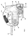
- Figure 1 is a schematic view of a jigsaw embodying the present invention
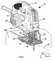
- Figure 2 is a view of the jigsaw shown in figure 1 from a front perspective
- Figure 3 is a schematic detailed view showing components of the jigsaw shown in figure 2.
- a jigsaw 10 embodying the present invention is shown.
- the jigsaw comprises a body 12, having a handle portion 14, a motor housing portion 16 and a gearbox portion 18.
- a base plate 20 is coupled to the housing by a bridge component 21 and comprises an underside surface 22 which is arranged to engage with a top surface of a work-piece during use.
- a reciprocating shaft 24 extends from the gearbox portion of the housing and comprises a blade clamp 26 at one end of the shaft.
- a saw blade 28 is disposed in the blade clamp such that the blade extends through an aperture 30 (see figure 2) in the base plate. During use, the blade is in engagement with the work-piece, as is understood by the skilled person.
- a motor is housed in the motor housing portion 16 of the body 12.
- the motor is coupled to a gearbox disposed in the gearbox portion 18 of the body12.
- Electrical power is supplied to the motor via a cord 31.
- electrical powered could also be supplied by batteries.
- a manually operable switch 32 is provided to allow an operator to interrupt electrical power to the motor. Power is supplied to the motor by depressing the switch into handle portion 14. When activated by the switch, rotorary motion of the motor is converted to linear reciprocating motion by the gearbox. The reciprocating shaft, and hence the blade coupled thereto, therefore move in a linear manner and perpendicular to the plain defined by the base plate.
- a fan is coupled to the motor and disposed between the motor and gearbox such that operation of the motor causes the fan to rotate. Rotation of the fan causes air to be drawn into the motor housing portion of the body through louvered slots 34. Having entered the body of the jigsaw, the air passes over the motor to cool components of the motor during use. The air then enters a volume surrounding the fan. Rotation of the fan causes the air to in the volume to exit the volume via an exit conduit 40.
- the jigsaw is shown disposed on a work-piece WP.
- the broken line 42 indicates the intended line along which the jigsaw is cutting, and arrow A indicates the cut direction.
- the work-piece is cut by the jigsaw in this manner.
- the exit conduit 40 is disposed on a side face 43 of the jigsaw body.
- the conduit extends from the fan volume inside the body to a point where the conduit then forms an enclosed channel on the outer surface of the body.
- An outlet 44 of the conduit is formed such that an air stream exiting the conduit is directed towards a portion of the work-piece close to the point where the saw blade passes through the top surface of the work-piece.
- the outlet is disposed close to the point where the body is coupled to the base plate 20.
- the direction of the air flow in the air stream is off-axis with respect to the line of cut 42.
- the air stream is angled with respect to the cut line 42 (the word “angled” being taken to mean that the air stream, or at least a component of the air stream in the plain of the work-piece, is neither parallel with or perpendicular to the cut line).
- Debris is thrown onto the top surface of the work-piece as the saw blade cuts through the work-piece.
- the air stream exiting the outlet 44 blows the debris away from area of work-piece being cut.
- the air stream is angled with respect to the cut line 42, the debris is blown away from the cut line thereby keeping the cut line visible to the operator during use.
- the air stream intercepting the debris is not interrupted by components of the jigsaw mechanism, such as a bell crank 46 used to impart pendulum motion on the saw blade during use. In other words, there is a clear line of sight between the outlet and the point on the work-piece where debris is ejected by the action of the saw blade.
- the outlet 44 comprises a nozzle member 48.
- the nozzle is arranged to direct the air stream passing through the outlet towards the area 50 of the work-piece WP where debris is ejected and may land or settle on the work-piece.
- This area 50 is within a 5-10 millimetres radius of the point where the cutting edge of the saw blade 28 engages with the work-piece. It can be seen that the air stream exiting the outlet and being directed by the nozzle is uninterrupted by components of the jigsaw on its path towards the work-piece area 50. It might be that the blade clamp 26 partially enters the air stream, but because of the clamps reciprocating motion, the air stream is only blocked or partially blocked for short periods of time.
- the jigsaw can be arranged such that all the air moved by the rotation of the fan passes through the outlet.
- the outlet is the only means by which air from the fan is able to be exhausted from the jigsaw's body.
- the angle at which the air stream exits the outlet with respect to the cut line could be arranged to be within 10° to 80° of the cut line in horizontal plane.
Landscapes
- Engineering & Computer Science (AREA)
- Mechanical Engineering (AREA)
- Sawing (AREA)
Abstract
Description
- This invention relates to a power tool having means for removing debris from the work-piece, particularly from an area of the work-piece close to the point at which work is done on the work-piece. The invention is described below with reference to electrically powered hand operated jigsaws. However, it is to be understood that the invention is not limited to jigsaws and could equally find application in other types of power tools, such as sabre saws, circular saws or the like.
- Jigsaws are well known in the field of electrically powered cutting tools. A saw blade is caused to reciprocate such that a work-piece is cut by the blade's action. Debris from the work-piece is thrown by the cutting blade onto work-piece. This debris can obscure to some extent the intended line of cut. As a result, an operator of the jigsaw has to blow or brush the debris off the work-piece before they can proceed with cutting the work-piece along the cut-line.
- This problem has been partially addressed by providing a flow of air to the area of the work-piece close to where the saw blade engages the work-piece.
-
DE 10338602 describes a jigsaw having airflow paths arranged such that a portion of air drawn into the body of the jigsaw by a fan on a drive motor is expelled from a nozzle disposed immediately behind the saw blade. Thus, the expelled air blows debris forward of the blade. - Likewise,
DE 3717585 describes a jigsaw having airflow paths arranged in the body of the saw such that air propelled by a motor fan is blown towards an area of the work-piece coincident with the point where the saw blade exits the work-piece. - The prior art devices discussed above only partially solve the problem of clearing debris from the intended direction along which the saw is cutting. The debris is blown forward of the saw, but some debris remains on the cut line, especially when the cut line is straight.
-
WO 2004080635 describes a jigsaw arranged to drive air via a connecting piece and bridge member towards a jigsaw blade in a direction transverse to a line of cutting action. A suction tube is provided, which can be attached to a vacuum cleaner, on an opposite side of the blade to the bridge member. This arrangement is relatively complex and requires a portion of the connecting piece to be moveable with respect to the bridge member when the angle of the cut is bevelled, that is, when the blade is not perpendicular to a top surface of the work-piece. - The present invention aims to ameliorate the prior art devices by providing a simplified debris blower on a power tool which suffers less from the problems associated with known debris blower arrangements.
- More specifically, the present invention provides an electrically powered manually operated tool, comprising a motor for driving an output shaft to which a saw blade can be coupled, a housing for housing the motor, a base plate coupled to the housing, said base plate comprising a surface arranged to contact a work-piece during use and an aperture through which a saw blade can pass to engage the work-piece, a fan arranged to be driven by the motor and thereby provide a stream of air, and an outlet through which a portion of the stream of air can pass, characterised in that the outlet is disposed on the housing to one side of a cut line along which a blade is arranged to cut when coupled to the output shaft, said outlet being arranged to direct the stream of air during use at a portion of the work-piece in engagement with the saw blade.
- Advantageously, the outlet directs the air across the cut line at an inclined angle (that is, an angle which is not parallel or perpendicular to the cut-line) thereby blowing debris from the top surface of the work-piece and away from the cut line. Disposing the outlet on the housing can simplify the design and reduce the components necessary for the debris blower. Disposing the outlet on the side of the housing, off axis from the cut line, provides a simple means for angling the air stream into debris becomes entrained with respect to the cut line. Thus, debris can be removed from the work area and carried away from the cut line thereby keeping the cut line visible, during use.
- Preferably, the fan is disposed in the housing, the outlet is in fluid communication with the fan via a conduit, and the housing comprises an inlet arranged to be in fluid communication with the fan such that during use air drawn into the inlet passes over the motor. Thus, the air can be utilised for cooling motor components.
- Preferably, during use the outlet directs the stream of air such that work-piece debris ejected by the saw blade is entrained in the stream of air.
- Preferably, the outlet comprises a nozzle. As a result, the velocity of the air exiting from the outlet can be increased thereby improving the removal rate of debris. Furthermore, the nozzle can more accurately direct the air stream to the work area of the work-piece.
- Preferably, the outlet is arranged to direct the stream of air at the work-piece at an angle of between 10° and 80° with respect to the cut line. More preferably, the angle is between 30° and 60°.
- An embodiment of the present invention is now described by way of example, with reference to the accompanying drawings described below.
- Figure 1 is a schematic view of a jigsaw embodying the present invention;
- Figure 2 is a view of the jigsaw shown in figure 1 from a front perspective; and
- Figure 3 is a schematic detailed view showing components of the jigsaw shown in figure 2.
- Referring to figure 1, a
jigsaw 10 embodying the present invention is shown. The jigsaw comprises abody 12, having ahandle portion 14, amotor housing portion 16 and agearbox portion 18. Abase plate 20 is coupled to the housing by abridge component 21 and comprises anunderside surface 22 which is arranged to engage with a top surface of a work-piece during use. Areciprocating shaft 24 extends from the gearbox portion of the housing and comprises ablade clamp 26 at one end of the shaft. Asaw blade 28 is disposed in the blade clamp such that the blade extends through an aperture 30 (see figure 2) in the base plate. During use, the blade is in engagement with the work-piece, as is understood by the skilled person. - A motor is housed in the
motor housing portion 16 of thebody 12. The motor is coupled to a gearbox disposed in thegearbox portion 18 of the body12. Electrical power is supplied to the motor via acord 31. Of course, electrical powered could also be supplied by batteries. A manuallyoperable switch 32 is provided to allow an operator to interrupt electrical power to the motor. Power is supplied to the motor by depressing the switch intohandle portion 14. When activated by the switch, rotorary motion of the motor is converted to linear reciprocating motion by the gearbox. The reciprocating shaft, and hence the blade coupled thereto, therefore move in a linear manner and perpendicular to the plain defined by the base plate. - A fan is coupled to the motor and disposed between the motor and gearbox such that operation of the motor causes the fan to rotate. Rotation of the fan causes air to be drawn into the motor housing portion of the body through
louvered slots 34. Having entered the body of the jigsaw, the air passes over the motor to cool components of the motor during use. The air then enters a volume surrounding the fan. Rotation of the fan causes the air to in the volume to exit the volume via anexit conduit 40. - Referring to figure 2, the jigsaw is shown disposed on a work-piece WP. The
broken line 42 indicates the intended line along which the jigsaw is cutting, and arrow A indicates the cut direction. The work-piece is cut by the jigsaw in this manner. - The
exit conduit 40 is disposed on aside face 43 of the jigsaw body. The conduit extends from the fan volume inside the body to a point where the conduit then forms an enclosed channel on the outer surface of the body. Anoutlet 44 of the conduit is formed such that an air stream exiting the conduit is directed towards a portion of the work-piece close to the point where the saw blade passes through the top surface of the work-piece. Preferably, the outlet is disposed close to the point where the body is coupled to thebase plate 20. Thus, the direction of the air flow in the air stream is off-axis with respect to the line ofcut 42. In other words, the air stream is angled with respect to the cut line 42 (the word "angled" being taken to mean that the air stream, or at least a component of the air stream in the plain of the work-piece, is neither parallel with or perpendicular to the cut line). - Debris is thrown onto the top surface of the work-piece as the saw blade cuts through the work-piece. The air stream exiting the
outlet 44 blows the debris away from area of work-piece being cut. Furthermore, because the air stream is angled with respect to thecut line 42, the debris is blown away from the cut line thereby keeping the cut line visible to the operator during use. Yet further, the air stream intercepting the debris is not interrupted by components of the jigsaw mechanism, such as a bell crank 46 used to impart pendulum motion on the saw blade during use. In other words, there is a clear line of sight between the outlet and the point on the work-piece where debris is ejected by the action of the saw blade. - Referring to figure 3, a portion of the jigsaw embodying the present invention is shown in more detail. The
outlet 44 comprises anozzle member 48. The nozzle is arranged to direct the air stream passing through the outlet towards thearea 50 of the work-piece WP where debris is ejected and may land or settle on the work-piece. Thisarea 50 is within a 5-10 millimetres radius of the point where the cutting edge of thesaw blade 28 engages with the work-piece. It can be seen that the air stream exiting the outlet and being directed by the nozzle is uninterrupted by components of the jigsaw on its path towards the work-piece area 50. It might be that theblade clamp 26 partially enters the air stream, but because of the clamps reciprocating motion, the air stream is only blocked or partially blocked for short periods of time. - As a result of the foregoing, it is possible to provide a simple and more compact arrangement for a jigsaw. The designer is no longer concerned with having to implement relatively complex arrangements of conduits or pipes from the motor fan to direct air to the work-piece. Furthermore, the bell crank and other jigsaw components can be located in positions which are more optimal to their operation without the need to compromise because of the need to provide sufficient airflow to the work-piece for the removal of debris therefrom. Yet further, angling the air flow with respect to the
cut line 42 removes the debris from the cut line thereby improving the visibility of the cut line during use. - The jigsaw can be arranged such that all the air moved by the rotation of the fan passes through the outlet. In other words, the outlet is the only means by which air from the fan is able to be exhausted from the jigsaw's body.
- The skilled person will envisage modifications to the embodiment of the present invention described above. For instance, the angle at which the air stream exits the outlet with respect to the cut line could be arranged to be within 10° to 80° of the cut line in horizontal plane.
Claims (6)
- An electrically powered manually operated tool, comprising
a motor for driving an output shaft to which a saw blade can be coupled,
a housing for housing the motor,
a base plate attached to the housing, said base plate comprising a surface arranged to contact a work-piece during use, and an aperture through which a saw blade can pass to engage the work-piece,
a fan arranged to be driven by the motor to provide a stream of air, and
an outlet through which a portion of the stream of air can pass,
characterised in that
the outlet is disposed on the housing to one side of a cut line along which a blade is arranged to cut when coupled to the output shaft, said outlet being arranged to direct the stream of air during use at a portion of the work-piece in engagement with the saw blade. - A tool according to claim 2, wherein the fan is disposed in the housing, the outlet is in fluid communication with the fan via a conduit, and the housing comprises an inlet arranged to be in fluid communication with the fan such that air drawn into the inlet passes over the motor.
- A tool according to claim 1 or 2, wherein during use the outlet directs the stream of air to a portion of work-piece such that debris ejected by the saw blade is entrained in the stream of air.
- A tool according to any preceding claim, wherein the outlet comprises a nozzle.
- A tool according to any preceding claim, wherein the outlet is arranged to direct the stream of air at the work-piece at an angle of between 10° and 80° with respect to the cut line.
- A tool according to claim 6, wherein the angle is between 30° and 60°.
Priority Applications (4)
| Application Number | Priority Date | Filing Date | Title |
|---|---|---|---|
| EP20050111379 EP1790432B1 (en) | 2005-11-28 | 2005-11-28 | Power toll such as jig saw having means for removing cutting debris from workpiece |
| AU2006203270A AU2006203270A1 (en) | 2005-11-28 | 2006-07-31 | Power tool having means for removing debris from workpiece |
| CN2006101435275A CN1974093B (en) | 2005-11-28 | 2006-11-10 | Power tool having means for removing debris from workpiece |
| US11/602,619 US20070169606A1 (en) | 2005-11-28 | 2006-11-21 | Power tool having means for removing debris from workpiece |
Applications Claiming Priority (1)
| Application Number | Priority Date | Filing Date | Title |
|---|---|---|---|
| EP20050111379 EP1790432B1 (en) | 2005-11-28 | 2005-11-28 | Power toll such as jig saw having means for removing cutting debris from workpiece |
Publications (2)
| Publication Number | Publication Date |
|---|---|
| EP1790432A1 true EP1790432A1 (en) | 2007-05-30 |
| EP1790432B1 EP1790432B1 (en) | 2014-01-08 |
Family
ID=36051552
Family Applications (1)
| Application Number | Title | Priority Date | Filing Date |
|---|---|---|---|
| EP20050111379 Expired - Lifetime EP1790432B1 (en) | 2005-11-28 | 2005-11-28 | Power toll such as jig saw having means for removing cutting debris from workpiece |
Country Status (4)
| Country | Link |
|---|---|
| US (1) | US20070169606A1 (en) |
| EP (1) | EP1790432B1 (en) |
| CN (1) | CN1974093B (en) |
| AU (1) | AU2006203270A1 (en) |
Cited By (3)
| Publication number | Priority date | Publication date | Assignee | Title |
|---|---|---|---|---|
| GB2462365A (en) * | 2008-08-07 | 2010-02-10 | Bosch Gmbh Robert | Hand-held power tool with blowing duct |
| EP2463049A1 (en) * | 2010-12-10 | 2012-06-13 | Makita Corporation | Cutting machine |
| CN114728408A (en) * | 2020-01-10 | 2022-07-08 | 喜利得股份公司 | Power tool with air cooling member and method of protecting a user of a power tool from dust |
Families Citing this family (10)
| Publication number | Priority date | Publication date | Assignee | Title |
|---|---|---|---|---|
| ATE419086T1 (en) * | 2006-03-18 | 2009-01-15 | Black & Decker Inc | JIGSAW WITH CHIP REMOVING DEVICE |
| DE102008041095A1 (en) * | 2008-08-07 | 2010-02-11 | Robert Bosch Gmbh | Hand tool |
| CN102233458B (en) * | 2010-04-21 | 2013-04-10 | 苏州宝时得电动工具有限公司 | Cutting machine |
| CN102581378B (en) * | 2011-01-14 | 2014-03-12 | 苏州宝时得电动工具有限公司 | Cutting tool |
| US9937572B2 (en) * | 2015-04-22 | 2018-04-10 | Wesley Harold Hutchcraft | Blade fan |
| CN104785853A (en) * | 2015-04-24 | 2015-07-22 | 哈尔滨工程大学 | Submarine pipeline cutting equipment |
| CN207326065U (en) * | 2016-07-01 | 2018-05-08 | 苏州宝时得电动工具有限公司 | Cutting tool |
| JP6331056B2 (en) * | 2017-03-13 | 2018-05-30 | 日立工機株式会社 | Portable electric cutting machine |
| DE102018102855A1 (en) * | 2017-08-11 | 2019-02-14 | Festool Gmbh | Hand machine tool with a suction connection |
| CN110744137B (en) * | 2019-10-17 | 2020-09-29 | 江苏金鼎建设集团有限公司 | Embedded pipeline cutter |
Citations (4)
| Publication number | Priority date | Publication date | Assignee | Title |
|---|---|---|---|---|
| DE7919565U1 (en) | 1979-07-07 | 1979-10-25 | Ohlsen, Harald, 2100 Hamburg | Device for blowing out saw cut surfaces |
| DE20310902U1 (en) * | 2003-07-16 | 2003-10-09 | Reuss, Harald, 97688 Bad Kissingen | Abluftumlenker |
| WO2004080635A1 (en) | 2003-03-13 | 2004-09-23 | Black & Decker Inc | Method and apparatus for removing dust from a workpiece |
| WO2005072921A1 (en) * | 2004-01-16 | 2005-08-11 | Robert Bosch Gmbh | Bevel quadrant and gearbox louver blower system |
Family Cites Families (6)
| Publication number | Priority date | Publication date | Assignee | Title |
|---|---|---|---|---|
| US5084971A (en) * | 1990-09-12 | 1992-02-04 | Remington Mark A | Sawdust blower attachment for power saws |
| US5199174A (en) * | 1992-04-13 | 1993-04-06 | Wild Jeffrey C | Sawdust removal apparatus |
| US5539985A (en) * | 1994-11-21 | 1996-07-30 | Wershe; Richard | Blower attachment for a circular saw |
| US5689884A (en) * | 1994-11-21 | 1997-11-25 | Wershe; Richard | Circular saw with blower |
| US20040112191A1 (en) * | 2002-12-11 | 2004-06-17 | One World Technologies Limited | Hose with optical device |
| JP3765425B2 (en) * | 2004-01-26 | 2006-04-12 | 日立工機株式会社 | Portable electric cutting machine |
-
2005
- 2005-11-28 EP EP20050111379 patent/EP1790432B1/en not_active Expired - Lifetime
-
2006
- 2006-07-31 AU AU2006203270A patent/AU2006203270A1/en not_active Abandoned
- 2006-11-10 CN CN2006101435275A patent/CN1974093B/en not_active Expired - Fee Related
- 2006-11-21 US US11/602,619 patent/US20070169606A1/en not_active Abandoned
Patent Citations (4)
| Publication number | Priority date | Publication date | Assignee | Title |
|---|---|---|---|---|
| DE7919565U1 (en) | 1979-07-07 | 1979-10-25 | Ohlsen, Harald, 2100 Hamburg | Device for blowing out saw cut surfaces |
| WO2004080635A1 (en) | 2003-03-13 | 2004-09-23 | Black & Decker Inc | Method and apparatus for removing dust from a workpiece |
| DE20310902U1 (en) * | 2003-07-16 | 2003-10-09 | Reuss, Harald, 97688 Bad Kissingen | Abluftumlenker |
| WO2005072921A1 (en) * | 2004-01-16 | 2005-08-11 | Robert Bosch Gmbh | Bevel quadrant and gearbox louver blower system |
Cited By (3)
| Publication number | Priority date | Publication date | Assignee | Title |
|---|---|---|---|---|
| GB2462365A (en) * | 2008-08-07 | 2010-02-10 | Bosch Gmbh Robert | Hand-held power tool with blowing duct |
| EP2463049A1 (en) * | 2010-12-10 | 2012-06-13 | Makita Corporation | Cutting machine |
| CN114728408A (en) * | 2020-01-10 | 2022-07-08 | 喜利得股份公司 | Power tool with air cooling member and method of protecting a user of a power tool from dust |
Also Published As
| Publication number | Publication date |
|---|---|
| AU2006203270A1 (en) | 2007-06-14 |
| EP1790432B1 (en) | 2014-01-08 |
| US20070169606A1 (en) | 2007-07-26 |
| CN1974093B (en) | 2011-02-16 |
| CN1974093A (en) | 2007-06-06 |
Similar Documents
| Publication | Publication Date | Title |
|---|---|---|
| CN100553842C (en) | Electric Handheld Cutting Tools | |
| CN100436016C (en) | Method and apparatus for removing debris from a workpiece | |
| EP1415746B1 (en) | Power tool | |
| US8371034B2 (en) | Dust collection cover attachable to cutter | |
| EP1260299B1 (en) | Reciprocating cutting tools having devices for limiting scattering of cutting chips | |
| EP1790432B1 (en) | Power toll such as jig saw having means for removing cutting debris from workpiece | |
| CN100446936C (en) | Handheld Power Tools | |
| AU2004218919B2 (en) | Method and apparatus for removing dust from a workpiece | |
| CN102416618B (en) | There is the electric tools manually guided of suction adapter | |
| CN101641192A (en) | Cutter | |
| US6173499B1 (en) | Vent cover for an electric saw | |
| GB2399314A (en) | Tool having rotatable adjustment means for power working member | |
| EP2463049B1 (en) | Cutting machine | |
| US20070033807A1 (en) | Planer with improved chip removal | |
| US20260097443A1 (en) | Circular saw | |
| GB2382793A (en) | Manually operated cutting or drilling tool with air actuator means | |
| CN104029181B (en) | hand tool | |
| JP2005014395A (en) | Dust collector of jigsaw |
Legal Events
| Date | Code | Title | Description |
|---|---|---|---|
| PUAI | Public reference made under article 153(3) epc to a published international application that has entered the european phase |
Free format text: ORIGINAL CODE: 0009012 |
|
| AK | Designated contracting states |
Kind code of ref document: A1 Designated state(s): AT BE BG CH CY CZ DE DK EE ES FI FR GB GR HU IE IS IT LI LT LU LV MC NL PL PT RO SE SI SK TR |
|
| AX | Request for extension of the european patent |
Extension state: AL BA HR MK YU |
|
| 17P | Request for examination filed |
Effective date: 20070606 |
|
| 17Q | First examination report despatched |
Effective date: 20070822 |
|
| AKX | Designation fees paid |
Designated state(s): AT BE BG CH CY CZ DE DK EE ES FI FR GB GR HU IE IS IT LI LT LU LV MC NL PL PT RO SE SI SK TR |
|
| GRAP | Despatch of communication of intention to grant a patent |
Free format text: ORIGINAL CODE: EPIDOSNIGR1 |
|
| GRAP | Despatch of communication of intention to grant a patent |
Free format text: ORIGINAL CODE: EPIDOSNIGR1 |
|
| INTG | Intention to grant announced |
Effective date: 20131004 |
|
| INTG | Intention to grant announced |
Effective date: 20131031 |
|
| GRAS | Grant fee paid |
Free format text: ORIGINAL CODE: EPIDOSNIGR3 |
|
| GRAA | (expected) grant |
Free format text: ORIGINAL CODE: 0009210 |
|
| AK | Designated contracting states |
Kind code of ref document: B1 Designated state(s): AT BE BG CH CY CZ DE DK EE ES FI FR GB GR HU IE IS IT LI LT LU LV MC NL PL PT RO SE SI SK TR |
|
| REG | Reference to a national code |
Ref country code: GB Ref legal event code: FG4D |
|
| REG | Reference to a national code |
Ref country code: CH Ref legal event code: EP |
|
| REG | Reference to a national code |
Ref country code: IE Ref legal event code: FG4D |
|
| REG | Reference to a national code |
Ref country code: AT Ref legal event code: REF Ref document number: 648390 Country of ref document: AT Kind code of ref document: T Effective date: 20140215 |
|
| REG | Reference to a national code |
Ref country code: DE Ref legal event code: R096 Ref document number: 602005042404 Country of ref document: DE Effective date: 20140220 |
|
| REG | Reference to a national code |
Ref country code: AT Ref legal event code: MK05 Ref document number: 648390 Country of ref document: AT Kind code of ref document: T Effective date: 20140108 |
|
| REG | Reference to a national code |
Ref country code: NL Ref legal event code: VDEP Effective date: 20140108 |
|
| REG | Reference to a national code |
Ref country code: LT Ref legal event code: MG4D |
|
| PG25 | Lapsed in a contracting state [announced via postgrant information from national office to epo] |
Ref country code: LT Free format text: LAPSE BECAUSE OF FAILURE TO SUBMIT A TRANSLATION OF THE DESCRIPTION OR TO PAY THE FEE WITHIN THE PRESCRIBED TIME-LIMIT Effective date: 20140108 Ref country code: IS Free format text: LAPSE BECAUSE OF FAILURE TO SUBMIT A TRANSLATION OF THE DESCRIPTION OR TO PAY THE FEE WITHIN THE PRESCRIBED TIME-LIMIT Effective date: 20140508 |
|
| PG25 | Lapsed in a contracting state [announced via postgrant information from national office to epo] |
Ref country code: AT Free format text: LAPSE BECAUSE OF FAILURE TO SUBMIT A TRANSLATION OF THE DESCRIPTION OR TO PAY THE FEE WITHIN THE PRESCRIBED TIME-LIMIT Effective date: 20140108 Ref country code: ES Free format text: LAPSE BECAUSE OF FAILURE TO SUBMIT A TRANSLATION OF THE DESCRIPTION OR TO PAY THE FEE WITHIN THE PRESCRIBED TIME-LIMIT Effective date: 20140108 Ref country code: FI Free format text: LAPSE BECAUSE OF FAILURE TO SUBMIT A TRANSLATION OF THE DESCRIPTION OR TO PAY THE FEE WITHIN THE PRESCRIBED TIME-LIMIT Effective date: 20140108 Ref country code: NL Free format text: LAPSE BECAUSE OF FAILURE TO SUBMIT A TRANSLATION OF THE DESCRIPTION OR TO PAY THE FEE WITHIN THE PRESCRIBED TIME-LIMIT Effective date: 20140108 Ref country code: PT Free format text: LAPSE BECAUSE OF FAILURE TO SUBMIT A TRANSLATION OF THE DESCRIPTION OR TO PAY THE FEE WITHIN THE PRESCRIBED TIME-LIMIT Effective date: 20140508 Ref country code: CY Free format text: LAPSE BECAUSE OF FAILURE TO SUBMIT A TRANSLATION OF THE DESCRIPTION OR TO PAY THE FEE WITHIN THE PRESCRIBED TIME-LIMIT Effective date: 20140108 Ref country code: SE Free format text: LAPSE BECAUSE OF FAILURE TO SUBMIT A TRANSLATION OF THE DESCRIPTION OR TO PAY THE FEE WITHIN THE PRESCRIBED TIME-LIMIT Effective date: 20140108 |
|
| PG25 | Lapsed in a contracting state [announced via postgrant information from national office to epo] |
Ref country code: BE Free format text: LAPSE BECAUSE OF FAILURE TO SUBMIT A TRANSLATION OF THE DESCRIPTION OR TO PAY THE FEE WITHIN THE PRESCRIBED TIME-LIMIT Effective date: 20140108 Ref country code: LV Free format text: LAPSE BECAUSE OF FAILURE TO SUBMIT A TRANSLATION OF THE DESCRIPTION OR TO PAY THE FEE WITHIN THE PRESCRIBED TIME-LIMIT Effective date: 20140108 |
|
| REG | Reference to a national code |
Ref country code: DE Ref legal event code: R097 Ref document number: 602005042404 Country of ref document: DE |
|
| PG25 | Lapsed in a contracting state [announced via postgrant information from national office to epo] |
Ref country code: DK Free format text: LAPSE BECAUSE OF FAILURE TO SUBMIT A TRANSLATION OF THE DESCRIPTION OR TO PAY THE FEE WITHIN THE PRESCRIBED TIME-LIMIT Effective date: 20140108 Ref country code: CZ Free format text: LAPSE BECAUSE OF FAILURE TO SUBMIT A TRANSLATION OF THE DESCRIPTION OR TO PAY THE FEE WITHIN THE PRESCRIBED TIME-LIMIT Effective date: 20140108 Ref country code: RO Free format text: LAPSE BECAUSE OF FAILURE TO SUBMIT A TRANSLATION OF THE DESCRIPTION OR TO PAY THE FEE WITHIN THE PRESCRIBED TIME-LIMIT Effective date: 20140108 Ref country code: EE Free format text: LAPSE BECAUSE OF FAILURE TO SUBMIT A TRANSLATION OF THE DESCRIPTION OR TO PAY THE FEE WITHIN THE PRESCRIBED TIME-LIMIT Effective date: 20140108 |
|
| PLBE | No opposition filed within time limit |
Free format text: ORIGINAL CODE: 0009261 |
|
| STAA | Information on the status of an ep patent application or granted ep patent |
Free format text: STATUS: NO OPPOSITION FILED WITHIN TIME LIMIT |
|
| PG25 | Lapsed in a contracting state [announced via postgrant information from national office to epo] |
Ref country code: PL Free format text: LAPSE BECAUSE OF FAILURE TO SUBMIT A TRANSLATION OF THE DESCRIPTION OR TO PAY THE FEE WITHIN THE PRESCRIBED TIME-LIMIT Effective date: 20140108 Ref country code: SK Free format text: LAPSE BECAUSE OF FAILURE TO SUBMIT A TRANSLATION OF THE DESCRIPTION OR TO PAY THE FEE WITHIN THE PRESCRIBED TIME-LIMIT Effective date: 20140108 |
|
| 26N | No opposition filed |
Effective date: 20141009 |
|
| REG | Reference to a national code |
Ref country code: DE Ref legal event code: R097 Ref document number: 602005042404 Country of ref document: DE Effective date: 20141009 |
|
| PG25 | Lapsed in a contracting state [announced via postgrant information from national office to epo] |
Ref country code: SI Free format text: LAPSE BECAUSE OF FAILURE TO SUBMIT A TRANSLATION OF THE DESCRIPTION OR TO PAY THE FEE WITHIN THE PRESCRIBED TIME-LIMIT Effective date: 20140108 |
|
| PG25 | Lapsed in a contracting state [announced via postgrant information from national office to epo] |
Ref country code: MC Free format text: LAPSE BECAUSE OF FAILURE TO SUBMIT A TRANSLATION OF THE DESCRIPTION OR TO PAY THE FEE WITHIN THE PRESCRIBED TIME-LIMIT Effective date: 20140108 Ref country code: LU Free format text: LAPSE BECAUSE OF FAILURE TO SUBMIT A TRANSLATION OF THE DESCRIPTION OR TO PAY THE FEE WITHIN THE PRESCRIBED TIME-LIMIT Effective date: 20141128 |
|
| REG | Reference to a national code |
Ref country code: CH Ref legal event code: PL |
|
| PG25 | Lapsed in a contracting state [announced via postgrant information from national office to epo] |
Ref country code: CH Free format text: LAPSE BECAUSE OF NON-PAYMENT OF DUE FEES Effective date: 20141130 Ref country code: LI Free format text: LAPSE BECAUSE OF NON-PAYMENT OF DUE FEES Effective date: 20141130 |
|
| REG | Reference to a national code |
Ref country code: IE Ref legal event code: MM4A |
|
| REG | Reference to a national code |
Ref country code: FR Ref legal event code: ST Effective date: 20150731 |
|
| PG25 | Lapsed in a contracting state [announced via postgrant information from national office to epo] |
Ref country code: IE Free format text: LAPSE BECAUSE OF NON-PAYMENT OF DUE FEES Effective date: 20141128 |
|
| PG25 | Lapsed in a contracting state [announced via postgrant information from national office to epo] |
Ref country code: FR Free format text: LAPSE BECAUSE OF NON-PAYMENT OF DUE FEES Effective date: 20141201 |
|
| PG25 | Lapsed in a contracting state [announced via postgrant information from national office to epo] |
Ref country code: BG Free format text: LAPSE BECAUSE OF FAILURE TO SUBMIT A TRANSLATION OF THE DESCRIPTION OR TO PAY THE FEE WITHIN THE PRESCRIBED TIME-LIMIT Effective date: 20140108 |
|
| PG25 | Lapsed in a contracting state [announced via postgrant information from national office to epo] |
Ref country code: GR Free format text: LAPSE BECAUSE OF FAILURE TO SUBMIT A TRANSLATION OF THE DESCRIPTION OR TO PAY THE FEE WITHIN THE PRESCRIBED TIME-LIMIT Effective date: 20140409 Ref country code: IT Free format text: LAPSE BECAUSE OF FAILURE TO SUBMIT A TRANSLATION OF THE DESCRIPTION OR TO PAY THE FEE WITHIN THE PRESCRIBED TIME-LIMIT Effective date: 20140108 |
|
| PG25 | Lapsed in a contracting state [announced via postgrant information from national office to epo] |
Ref country code: HU Free format text: LAPSE BECAUSE OF FAILURE TO SUBMIT A TRANSLATION OF THE DESCRIPTION OR TO PAY THE FEE WITHIN THE PRESCRIBED TIME-LIMIT; INVALID AB INITIO Effective date: 20051128 Ref country code: TR Free format text: LAPSE BECAUSE OF FAILURE TO SUBMIT A TRANSLATION OF THE DESCRIPTION OR TO PAY THE FEE WITHIN THE PRESCRIBED TIME-LIMIT Effective date: 20140108 |
|
| PGFP | Annual fee paid to national office [announced via postgrant information from national office to epo] |
Ref country code: DE Payment date: 20181113 Year of fee payment: 14 |
|
| PGFP | Annual fee paid to national office [announced via postgrant information from national office to epo] |
Ref country code: GB Payment date: 20181128 Year of fee payment: 14 |
|
| REG | Reference to a national code |
Ref country code: DE Ref legal event code: R119 Ref document number: 602005042404 Country of ref document: DE |
|
| GBPC | Gb: european patent ceased through non-payment of renewal fee |
Effective date: 20191128 |
|
| PG25 | Lapsed in a contracting state [announced via postgrant information from national office to epo] |
Ref country code: DE Free format text: LAPSE BECAUSE OF NON-PAYMENT OF DUE FEES Effective date: 20200603 Ref country code: GB Free format text: LAPSE BECAUSE OF NON-PAYMENT OF DUE FEES Effective date: 20191128 |