EP1790411A1 - Apparatus for organic synthesis and reactions - Google Patents
Apparatus for organic synthesis and reactions Download PDFInfo
- Publication number
- EP1790411A1 EP1790411A1 EP06256020A EP06256020A EP1790411A1 EP 1790411 A1 EP1790411 A1 EP 1790411A1 EP 06256020 A EP06256020 A EP 06256020A EP 06256020 A EP06256020 A EP 06256020A EP 1790411 A1 EP1790411 A1 EP 1790411A1
- Authority
- EP
- European Patent Office
- Prior art keywords
- reaction
- channel
- reagent
- organic synthesis
- reactions
- Prior art date
- Legal status (The legal status is an assumption and is not a legal conclusion. Google has not performed a legal analysis and makes no representation as to the accuracy of the status listed.)
- Withdrawn
Links
- 238000003786 synthesis reaction Methods 0.000 title claims abstract description 44
- 238000006053 organic reaction Methods 0.000 title claims description 14
- 239000003153 chemical reaction reagent Substances 0.000 claims abstract description 111
- 238000006243 chemical reaction Methods 0.000 claims abstract description 104
- 239000012295 chemical reaction liquid Substances 0.000 claims abstract description 43
- 238000004891 communication Methods 0.000 claims abstract description 16
- 239000012530 fluid Substances 0.000 claims abstract description 8
- 239000011521 glass Substances 0.000 claims description 43
- 239000000758 substrate Substances 0.000 claims description 31
- 238000001514 detection method Methods 0.000 claims description 12
- 239000010453 quartz Substances 0.000 claims description 9
- VYPSYNLAJGMNEJ-UHFFFAOYSA-N silicon dioxide Inorganic materials O=[Si]=O VYPSYNLAJGMNEJ-UHFFFAOYSA-N 0.000 claims description 9
- 239000000126 substance Substances 0.000 claims description 8
- 238000007599 discharging Methods 0.000 claims description 5
- 238000005553 drilling Methods 0.000 claims description 5
- 239000011347 resin Substances 0.000 claims description 5
- 229920005989 resin Polymers 0.000 claims description 5
- 238000001039 wet etching Methods 0.000 claims description 5
- 230000015572 biosynthetic process Effects 0.000 claims description 2
- 238000005481 NMR spectroscopy Methods 0.000 description 21
- 238000000034 method Methods 0.000 description 14
- 239000000523 sample Substances 0.000 description 13
- 239000007788 liquid Substances 0.000 description 12
- 239000007795 chemical reaction product Substances 0.000 description 8
- 238000013461 design Methods 0.000 description 7
- 239000004696 Poly ether ether ketone Substances 0.000 description 6
- 229920002530 polyetherether ketone Polymers 0.000 description 6
- 238000011160 research Methods 0.000 description 6
- 239000004809 Teflon Substances 0.000 description 5
- 239000000463 material Substances 0.000 description 5
- 239000000203 mixture Substances 0.000 description 5
- 238000004458 analytical method Methods 0.000 description 4
- 238000004519 manufacturing process Methods 0.000 description 4
- 230000003466 anti-cipated effect Effects 0.000 description 3
- 238000003754 machining Methods 0.000 description 3
- 238000002156 mixing Methods 0.000 description 3
- 238000000465 moulding Methods 0.000 description 3
- 239000000565 sealant Substances 0.000 description 3
- 238000004435 EPR spectroscopy Methods 0.000 description 2
- 238000010420 art technique Methods 0.000 description 2
- 238000010276 construction Methods 0.000 description 2
- 238000005520 cutting process Methods 0.000 description 2
- 238000005516 engineering process Methods 0.000 description 2
- 239000004033 plastic Substances 0.000 description 2
- 239000002904 solvent Substances 0.000 description 2
- 238000012916 structural analysis Methods 0.000 description 2
- 239000000853 adhesive Substances 0.000 description 1
- 230000001070 adhesive effect Effects 0.000 description 1
- 239000007806 chemical reaction intermediate Substances 0.000 description 1
- 238000007865 diluting Methods 0.000 description 1
- 238000000132 electrospray ionisation Methods 0.000 description 1
- 238000002474 experimental method Methods 0.000 description 1
- 230000031700 light absorption Effects 0.000 description 1
- 238000001819 mass spectrum Methods 0.000 description 1
- 238000005259 measurement Methods 0.000 description 1
- 230000007246 mechanism Effects 0.000 description 1
- 239000000047 product Substances 0.000 description 1
- 238000004451 qualitative analysis Methods 0.000 description 1
- 239000002683 reaction inhibitor Substances 0.000 description 1
- 239000007921 spray Substances 0.000 description 1
- 230000003068 static effect Effects 0.000 description 1
Images




Classifications
-
- B—PERFORMING OPERATIONS; TRANSPORTING
- B01—PHYSICAL OR CHEMICAL PROCESSES OR APPARATUS IN GENERAL
- B01J—CHEMICAL OR PHYSICAL PROCESSES, e.g. CATALYSIS OR COLLOID CHEMISTRY; THEIR RELEVANT APPARATUS
- B01J19/00—Chemical, physical or physico-chemical processes in general; Their relevant apparatus
- B01J19/0093—Microreactors, e.g. miniaturised or microfabricated reactors
-
- B—PERFORMING OPERATIONS; TRANSPORTING
- B01—PHYSICAL OR CHEMICAL PROCESSES OR APPARATUS IN GENERAL
- B01F—MIXING, e.g. DISSOLVING, EMULSIFYING OR DISPERSING
- B01F25/00—Flow mixers; Mixers for falling materials, e.g. solid particles
- B01F25/40—Static mixers
- B01F25/42—Static mixers in which the mixing is affected by moving the components jointly in changing directions, e.g. in tubes provided with baffles or obstructions
- B01F25/43—Mixing tubes, e.g. wherein the material is moved in a radial or partly reversed direction
- B01F25/433—Mixing tubes wherein the shape of the tube influences the mixing, e.g. mixing tubes with varying cross-section or provided with inwardly extending profiles
-
- B—PERFORMING OPERATIONS; TRANSPORTING
- B01—PHYSICAL OR CHEMICAL PROCESSES OR APPARATUS IN GENERAL
- B01F—MIXING, e.g. DISSOLVING, EMULSIFYING OR DISPERSING
- B01F25/00—Flow mixers; Mixers for falling materials, e.g. solid particles
- B01F25/40—Static mixers
- B01F25/42—Static mixers in which the mixing is affected by moving the components jointly in changing directions, e.g. in tubes provided with baffles or obstructions
- B01F25/43—Mixing tubes, e.g. wherein the material is moved in a radial or partly reversed direction
- B01F25/433—Mixing tubes wherein the shape of the tube influences the mixing, e.g. mixing tubes with varying cross-section or provided with inwardly extending profiles
- B01F25/4331—Mixers with bended, curved, coiled, wounded mixing tubes or comprising elements for bending the flow
-
- B—PERFORMING OPERATIONS; TRANSPORTING
- B01—PHYSICAL OR CHEMICAL PROCESSES OR APPARATUS IN GENERAL
- B01F—MIXING, e.g. DISSOLVING, EMULSIFYING OR DISPERSING
- B01F33/00—Other mixers; Mixing plants; Combinations of mixers
- B01F33/30—Micromixers
-
- G—PHYSICS
- G01—MEASURING; TESTING
- G01R—MEASURING ELECTRIC VARIABLES; MEASURING MAGNETIC VARIABLES
- G01R33/00—Arrangements or instruments for measuring magnetic variables
- G01R33/20—Arrangements or instruments for measuring magnetic variables involving magnetic resonance
- G01R33/28—Details of apparatus provided for in groups G01R33/44 - G01R33/64
- G01R33/30—Sample handling arrangements, e.g. sample cells, spinning mechanisms
- G01R33/302—Miniaturized sample handling arrangements for sampling small quantities, e.g. flow-through microfluidic NMR chips
-
- G—PHYSICS
- G01—MEASURING; TESTING
- G01R—MEASURING ELECTRIC VARIABLES; MEASURING MAGNETIC VARIABLES
- G01R33/00—Arrangements or instruments for measuring magnetic variables
- G01R33/20—Arrangements or instruments for measuring magnetic variables involving magnetic resonance
- G01R33/28—Details of apparatus provided for in groups G01R33/44 - G01R33/64
- G01R33/30—Sample handling arrangements, e.g. sample cells, spinning mechanisms
- G01R33/307—Sample handling arrangements, e.g. sample cells, spinning mechanisms specially adapted for moving the sample relative to the MR system, e.g. spinning mechanisms, flow cells or means for positioning the sample inside a spectrometer
-
- B—PERFORMING OPERATIONS; TRANSPORTING
- B01—PHYSICAL OR CHEMICAL PROCESSES OR APPARATUS IN GENERAL
- B01J—CHEMICAL OR PHYSICAL PROCESSES, e.g. CATALYSIS OR COLLOID CHEMISTRY; THEIR RELEVANT APPARATUS
- B01J2219/00—Chemical, physical or physico-chemical processes in general; Their relevant apparatus
- B01J2219/00781—Aspects relating to microreactors
- B01J2219/00783—Laminate assemblies, i.e. the reactor comprising a stack of plates
-
- B—PERFORMING OPERATIONS; TRANSPORTING
- B01—PHYSICAL OR CHEMICAL PROCESSES OR APPARATUS IN GENERAL
- B01J—CHEMICAL OR PHYSICAL PROCESSES, e.g. CATALYSIS OR COLLOID CHEMISTRY; THEIR RELEVANT APPARATUS
- B01J2219/00—Chemical, physical or physico-chemical processes in general; Their relevant apparatus
- B01J2219/00781—Aspects relating to microreactors
- B01J2219/00819—Materials of construction
- B01J2219/00824—Ceramic
- B01J2219/00826—Quartz
-
- B—PERFORMING OPERATIONS; TRANSPORTING
- B01—PHYSICAL OR CHEMICAL PROCESSES OR APPARATUS IN GENERAL
- B01J—CHEMICAL OR PHYSICAL PROCESSES, e.g. CATALYSIS OR COLLOID CHEMISTRY; THEIR RELEVANT APPARATUS
- B01J2219/00—Chemical, physical or physico-chemical processes in general; Their relevant apparatus
- B01J2219/00781—Aspects relating to microreactors
- B01J2219/00819—Materials of construction
- B01J2219/00831—Glass
-
- B—PERFORMING OPERATIONS; TRANSPORTING
- B01—PHYSICAL OR CHEMICAL PROCESSES OR APPARATUS IN GENERAL
- B01J—CHEMICAL OR PHYSICAL PROCESSES, e.g. CATALYSIS OR COLLOID CHEMISTRY; THEIR RELEVANT APPARATUS
- B01J2219/00—Chemical, physical or physico-chemical processes in general; Their relevant apparatus
- B01J2219/00781—Aspects relating to microreactors
- B01J2219/00819—Materials of construction
- B01J2219/00833—Plastic
-
- B—PERFORMING OPERATIONS; TRANSPORTING
- B01—PHYSICAL OR CHEMICAL PROCESSES OR APPARATUS IN GENERAL
- B01J—CHEMICAL OR PHYSICAL PROCESSES, e.g. CATALYSIS OR COLLOID CHEMISTRY; THEIR RELEVANT APPARATUS
- B01J2219/00—Chemical, physical or physico-chemical processes in general; Their relevant apparatus
- B01J2219/00781—Aspects relating to microreactors
- B01J2219/00851—Additional features
- B01J2219/00858—Aspects relating to the size of the reactor
- B01J2219/0086—Dimensions of the flow channels
-
- B—PERFORMING OPERATIONS; TRANSPORTING
- B01—PHYSICAL OR CHEMICAL PROCESSES OR APPARATUS IN GENERAL
- B01J—CHEMICAL OR PHYSICAL PROCESSES, e.g. CATALYSIS OR COLLOID CHEMISTRY; THEIR RELEVANT APPARATUS
- B01J2219/00—Chemical, physical or physico-chemical processes in general; Their relevant apparatus
- B01J2219/00781—Aspects relating to microreactors
- B01J2219/00851—Additional features
- B01J2219/00858—Aspects relating to the size of the reactor
- B01J2219/00862—Dimensions of the reaction cavity itself
-
- B—PERFORMING OPERATIONS; TRANSPORTING
- B01—PHYSICAL OR CHEMICAL PROCESSES OR APPARATUS IN GENERAL
- B01J—CHEMICAL OR PHYSICAL PROCESSES, e.g. CATALYSIS OR COLLOID CHEMISTRY; THEIR RELEVANT APPARATUS
- B01J2219/00—Chemical, physical or physico-chemical processes in general; Their relevant apparatus
- B01J2219/00781—Aspects relating to microreactors
- B01J2219/00851—Additional features
- B01J2219/00871—Modular assembly
-
- B—PERFORMING OPERATIONS; TRANSPORTING
- B01—PHYSICAL OR CHEMICAL PROCESSES OR APPARATUS IN GENERAL
- B01J—CHEMICAL OR PHYSICAL PROCESSES, e.g. CATALYSIS OR COLLOID CHEMISTRY; THEIR RELEVANT APPARATUS
- B01J2219/00—Chemical, physical or physico-chemical processes in general; Their relevant apparatus
- B01J2219/00781—Aspects relating to microreactors
- B01J2219/00889—Mixing
-
- B—PERFORMING OPERATIONS; TRANSPORTING
- B01—PHYSICAL OR CHEMICAL PROCESSES OR APPARATUS IN GENERAL
- B01J—CHEMICAL OR PHYSICAL PROCESSES, e.g. CATALYSIS OR COLLOID CHEMISTRY; THEIR RELEVANT APPARATUS
- B01J2219/00—Chemical, physical or physico-chemical processes in general; Their relevant apparatus
- B01J2219/00781—Aspects relating to microreactors
- B01J2219/00891—Feeding or evacuation
-
- B—PERFORMING OPERATIONS; TRANSPORTING
- B01—PHYSICAL OR CHEMICAL PROCESSES OR APPARATUS IN GENERAL
- B01J—CHEMICAL OR PHYSICAL PROCESSES, e.g. CATALYSIS OR COLLOID CHEMISTRY; THEIR RELEVANT APPARATUS
- B01J2219/00—Chemical, physical or physico-chemical processes in general; Their relevant apparatus
- B01J2219/00781—Aspects relating to microreactors
- B01J2219/0095—Control aspects
- B01J2219/00952—Sensing operations
- B01J2219/00968—Type of sensors
- B01J2219/0097—Optical sensors
Definitions
- the present invention relates to an apparatus for organic synthesis and reactions and, more particularly, to an apparatus which is used for organic synthesis and reactions and permits analysis of reaction mechanisms and reaction intermediate structures.
- microchip technology A technique for causing plural substances to mix and react with each other in a quite small space is known as microchip technology or microreactor technology and expected to be put into practical use to provide increased chemical reaction rates and improved efficiencies.
- Microchip reactors for chemical synthesis are often made of glass because of its excellent chemical resistance. Since it is difficult to directly connect a tube, which is used to introduce a synthesis reagent, with a microchannel in a microchip made of glass, it is customary to connect the tube with a holder via a connector after the microchip reactor is held with the holder.
- a reagent solution having high viscosity may be used depending on the kind of synthesis reaction.
- the reagent may clog up the channel after introduction of the reagent. Especially, the channel tends to be clogged up near tube joints.
- Microreactor products used for chemical synthesis have already been sold from some manufacturers.
- the microreactors are chiefly made of glass.
- a commercially available microreactor 100 for mixing of two reagents is shown in Fig. 7a-c.
- the glass microreactor 100 is composed of two plates. A microchannel is formed in one of the plates. A fluid inlet hole 102 and a fluid exit hole are formed in the other. The two plates are bonded together by thermocompression.
- This microreactor is held to a holder 110.
- Tubes 124 for introduction of reagents are connected with the microreactor using connectors 120.
- Fig. 7c shows the structure of a connector 120.
- a Teflon TM screw 122 is screwed into the chip holder 110 and into contact with the glass chip 100.
- a Teflon TM tube 124 passes through the screw 122 to the fluid inlet hole 102.
- An O-ring seal 126 is provided between the screw 122 and the glass microreactor 100.
- the tubes 124 are connected with syringe pumps. Reagent solutions are introduced into the microreactor by the syringe pumps.
- the introduced reagents are made to meet at the Y-shaped portion of the channel and mixed.
- the reagents are made to react with each other in the downstream channel, thus producing reaction products.
- a well-known on-line method of detecting reaction products is a thermal lens microscope technique. Where a measurement is performed using a mass spectrometer (MS) or nuclear magnetic resonance spectrometer (NMR) to make structural analysis of reaction products, it is required that the reaction products be collected at the exit of the microreactor and that the sample be introduced into the MS or NMR off-line.
- MS mass spectrometer
- NMR nuclear magnetic resonance spectrometer
- a monograph has been published describing a research in which a circular liquid reservoir is formed in a channel within a microchip reactor as shown in Fig. 8, a microcoil is brought close to the reservoir, and a trace amount of sample is investigated.
- Microcoils or probes dedicated for microchip reactors are at a research stage. There are almost no applications to chemical synthesis.
- Itemreferences for figure 8 are as follows: Helmholtz MicroCoil 130; electrical bridge 131; bonding pads 132; glass substrate 133; fill channels 134; sample chamber 135; and glass substrate 136.
- Reaction reagents are mixed and reacted with each other using a static mixer.
- the reaction liquid is guided into a probe for flow NMR via a line, and an NMR measurement is performed.
- This research is at a practical level.
- the experiment needs a flow NMR probe.
- the distance from the reaction portion to the position in the NMR magnet irradiated with an RF magnetic field is long.
- ESI nanoelectrospray
- top plastic chip 140 bottom plastic chip 141; channel exit 142; triangle tip 143; nano ESI spray nozzle 144; reservoir hole 145; embossed fluidic channel; and emitter film 147.
- Non-patent reference 1 Japanese Utility Model No. S57-75558
- Non-patent reference 2 Published Technical Report No. 2004-502547 of the Japan Institute of Invention and Innovation
- Non-patent reference 3 J.H. Walton et al., Analytical Chemistry, Vol. 75, pp. 5030-5036 (2003)
- Non-patent reference 4 J. Kameoka et al., Analytical Chemistry, Vol. 74, pp. 5897-5901 (2002)
- Microchip reactors and microreactors for chemical analysis have the following problems:
- the present invention has been made in view of the foregoing problems. It would be desirable to provide a microchip reactor which is for use in organic synthesis and which can be used in combination with many analytical instruments.
- an organic synthesis reactor in which fluids are mixed in a very narrow space and reacted in multiple stages.
- the reactor has an introduction portion for introducing plural reagents from plural channels and a reaction portion disconnectably connected with the introduction portion. Where needed, the introduction portion mixes the introduced reagents and causes them to react with each other.
- a reagent or reaction liquid introduced from the introduction portion is mixed and reacted with other reagent.
- the introduction portion has an inlet channel for introducing a reagent, introduced from the outside, into the reaction portion and a first discharge channel for discharging the reaction liquid, discharged from the reaction portion, to the outside.
- the reaction portion has a reaction channel in communication with the inlet channel and a second discharge channel. The reaction channel causes plural reagents sent in from the inlet channel to mix and react.
- the second discharge channel places the reaction channel into communication with the first discharge channel to return the reaction liquid produced in the reaction channel to the introduction portion.
- the introduction portion is a microchip having a substrate made of a resin having chemical resistance.
- the substrate is provided with a microchannel.
- the reaction portion is a microchip having a substrate made of glass or quartz, the substrate being provided with a microchannel.
- the introduction portion has an inlet hole for introducing a reagent and a discharge hole for discharging the reaction liquid.
- the inlet hole and the discharge hole are flush with each other.
- the microchannels are formed on both surfaces of the substrate made of glass or quartz by wet etching or drilling. Then, the substrate having the microchannels is sandwiched between two plates of glass or quartz. The substrate and the plates are bonded together by thermocompression, thus completing the reactor.
- the substrate has a thickness of 1 to 5 mm.
- reaction portion has been finished in a cylindrical or prismatic form having a length of 50 to 300 mm and a maximum width of 2 to 10 mm.
- the microchannels have a width and a depth of 50 to 500 ⁇ m.
- the reaction portion has a detection portion used in combination with an analytical instrument for analyzing the reaction liquid.
- the analytical instrument is at least one of NMR, ESR, and thermal lens microscope.
- an electrospray nozzle for use in combination with a mass spectrometer (MS) for analyzing the reaction liquid is mounted in the discharge hole in the introduction portion for discharging the reaction liquid.
- MS mass spectrometer
- the organic synthesis reactor according to an embodiment of the present invention is designed as described above, the reactor can be fabricated in a microchip form capable of being used in combination with many analytical instruments.
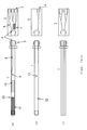
- FIG. 1 there is shown an organic synthesis reactor according to one embodiment of the present invention.
- Figs. 1a-c show top, bottom and side views, respectively.
- the reactor has a reagent introduction-and-reaction portion 2 that is connected at a contact portion 4 with an extensional reaction portion 1 via a connector jig 3.
- the extensional reaction portion 1 is made of a glass substrate having a thickness of 1 to 5 mm. Microchannels are formed on both surfaces of the glass substrate by wet etching or drilling.
- the glass substrate is provided with a through-hole 12 to permit a reagent solution to flow from the channel in the front surface to the channel in the rear surface.
- the width and depth of the channels are 50 to 500 ⁇ m.
- the design of the channels and machining method can be modified according to the purpose of use.
- the glass substrate having the microchannels are then held between two glass plates. These glass substrate and glass plates are bonded together by thermocompression.
- the whole assembly is finished in a cylindrical or prismatic form by a cutting technique.
- a glass stock may be machined into a semicylindrical form, and microchannels may be formed in this semicylindrical form.
- the length of the extensional reaction portion 1 is 50 to 300 mm.
- the diameter of the cylindrical form or the maximum width of the prismatic form is 2 to 10 mm.
- Screw holes are formed in the reagent introduction-and-reaction portion 2 to permit connection of tubes. Also, channels are formed in this portion 2. When the extensional reaction portion 1 and the reagent introduction-and-reaction portion 2 have been connected, their channels are aligned. Consequently, a reagent solution can be passed through the channels.
- the connector jig 3 has guide portions to facilitate aligning the extensional reaction portion 1 and reagent introduction-and-reaction portion 2.
- the contact portion 4 is surface-treated or used in combination with a sealant to prevent liquid leakage.
- Three reagent inlet holes 5 are formed in the reagent introduction-and-reaction portion 2. Two of the 3 inlet holes 5 meet each other and are combined into one conduit immediately ahead of a first reaction portion 7 formed within the reagent introduction-and-reaction portion 2. The conduit passes through the first reaction portion 7 of the bent channel, where a first reaction between reagents is produced. The conduit is in communication with a first reaction liquid channel 8 formed in the extensional reaction portion 1.
- a reagent inlet channel 6 extends from the remaining one of the reagent inlet holes 5 and meets the first reaction liquid channel 8 in a second reaction-and-mixture portion 9 formed in the extensional reaction portion 1, thus forming one conduit.
- This conduit is in communication with a second reaction portion 10 of the bent channel, where a second reaction between the reagents is induced.
- the second reaction portion 10 is in communication with a detection channel 11 of the bent channel.
- the second reaction portion 10 passes through a through-hole 12 and reaches the rear side of the extensional reaction portion 1, the through-hole 12 being formed in the vertical direction.
- the second reaction portion 10 then passes into the reaction liquid discharge hole 14 through a reaction liquid discharge channel 13.
- the 3 reagent inlet holes 5 and reaction liquid discharge hole 14 are formed in the same side surface of the reagent introduction-and-reaction portion 2.
- the microchannels in the microchip are formed in both top surface side and bottom surface side of the reagent introduction-and-reaction portion 2 and extensional reaction portion 1. That is, the present embodiment is characterized in that there are two layers of channels.
- the material of the organic synthesis reactor is so selected that the reactor can be used in a temperature range from -70°C to +200°C.
- the reagent introduction-and-reaction portion 2 is preferably made of a chemical resistant resin such as PEEK (polyetheretherketone), Teflon TM , or Diflon.
- the extensional reaction portion 1 is made of glass or quartz.
- the channels inside the reagent introduction-and-reaction portion 2 tend to be clogged up especially easily. Consequently, it can be anticipated that the running cost of the reactor in operation will be reduced by designing this portion tending to be clogged up as a replaceable external part attached to the extensional reaction portion 1.
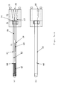
- Fig. 2 shows an organic synthesis reactor according to another embodiment of the present invention.
- Figs. 2a-c show top, bottom and side views, respectively.
- the reactor has a reagent inlet portion 22 that is connected at a contact portion 24 with a reagent reaction portion 21 via a connector jig 23.
- the reagent reaction portion 21 is made of a glass substrate having a thickness of 1 to 5 mm. Microchannels are formed on both surfaces of the glass substrate by wet etching or drilling.
- the glass substrate is provided with a through-hole 33 to permit a reagent solution to flow from the channel in the front surface to the channel in the rear surface.
- the width and depth of the channels are 50 to 500 ⁇ m.
- the design of the channels and machining method can be modified according to the purpose of use.
- the glass substrate having the microchannels are then held between two glass plates. These glass substrate and glass plates are bonded together by thermocompression.
- the whole assembly is finished in a cylindrical or prismatic form by a cutting technique.
- a glass stock may be machined into a semicylindrical form, and microchannels may be formed in this semicylindrical form.
- the length of the reagent reaction portion 21 is 50 to 300 mm.
- the diameter of the cylindrical form or the maximum width of the prismatic form is 2 to 10 mm.
- Screw holes are formed in the reagent inlet portion 22 to permit connection of tubes. Also, channels are formed in the inlet portion 22. When the reagent reaction portion 21 and the reagent inlet portion 22 have been connected, their channels are aligned. Consequently, a reagent solution can be passed through the channels.
- the connector jig 23 has guide portions to facilitate aligning the reagent reaction portion 21 and reagent inlet portion 22.
- the contact portion 24 is surface-treated or used in combination with a sealant to prevent liquid leakage.
- Three reagent inlet holes 25 are formed in the reagent inlet portion 22 and are in communication with three reaction liquid channels 27, respectively, formed in the reagent reaction portion 21.
- Two of the 3 inlet holes 25 meet each other and are combined into one conduit in the first reaction-and-mixture portion 28.
- the conduit is in communication with the first reaction portion 29 of the bent channel, where a first reaction between reagents is produced.
- the conduit then meets another reaction liquid channel 27 in the second reaction-and-mixture portion 30 to form one conduit which is in communication with the second reaction portion 31 of the bent channel, where a second reaction between the reagents is induced.
- the second reaction portion 31 is in communication with a detection channel 32 of the bent channel.
- the detection channel 32 passes through a through-hole 33 and reaches the rear side of the reagent reaction portion 21, the through-hole 33 being formed in the vertical direction.
- the second reaction liquid then passes into the reaction liquid discharge hole 35 through a reaction liquid discharge channel 34.
- the 3 reagent inlet holes 25 and reaction liquid discharge hole 35 are formed in the same side surface of the reagent inlet portion 22.
- the microchannels in the microchip are formed in both top surface side and bottom surface side of the reagent inlet portion 22 and reagent reaction portion 21. That is, the present embodiment is characterized in that there are two layers of channels.
- the material of the organic synthesis reactor is so selected that the reactor can be used in a temperature range from -70°C to +200°C.
- the reagent inlet portion 22 is preferably made of a chemical resistant resin such as PEEK (polyetheretherketone), Teflon TM , or Diflon.
- the reagent reaction portion 21 is made of glass or quartz.
- the channels inside the reagent inlet portion 22 tend to be clogged up especially easily. Consequently, it can be anticipated that the running cost of the reactor in operation will be reduced by designing this portion tending to be clogged up as a replaceable external part attached to the reagent reaction portion 21.
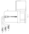
- Fig. 3 shows an organic synthesis reactor according to a further embodiment of the present invention.
- Figs. 3a and 3b show a top and a bottom view, respectively.
- the reactor has a reagent inlet portion 52 that is connected at a contact portion 54 with a reagent reaction portion 51 via a connector jig 53 and using screws 55.
- the reagent reaction portion 51 is made of a glass substrate having a thickness of 1 to 5 mm. Microchannels are formed on both surfaces of the glass substrate by wet etching or drilling.
- the glass substrate is provided with a through-hole 64 to permit a reagent solution to flow from the channel in the front surface to the channel in the rear surface.
- the width and depth of the channels are 50 to 500 ⁇ m.
- the design of the channels and machining method can be modified according to the purpose of use.
- the glass substrate having the microchannels are then held between two glass plates. These glass substrate and glass plates are bonded together by thermocompression.
- One end portion of the assembly is cut into an elongated T-shaped form.
- the end portion of the reagent reaction portion 51 is shaped like the letter T to press and join the reagent inlet portion 52 by the connector jig 53.
- the T-shaped end portion of the reagent reaction portion 51 is made asymmetrical right and left to prevent the senses of the reagent reaction portion 51 and reagent inlet portion 52 from being confused when they are connected.
- the connector jig 53 has a structure for recognizing the asymmetrical portion or an asymmetrical fitting portion.
- Screw holes are formed in the reagent inlet portion 52 to permit connection of tubes. Also, channels are formed in the inlet portion 52. When the reagent reaction portion 51 and the reagent inlet portion 52 have been connected, their channels are aligned. Consequently, a reagent solution can be passed through the channels.
- the contact portion 54 is surface-treated or used in combination with a sealant to prevent liquid leakage.
- Three reagent inlet holes 56 are formed in the reagent inlet portion 52 and are in communication via three reagent inlet channels 57, respectively, with three reaction liquid channels 58, respectively, formed in the reagent reaction portion 51.
- Two of the 3 inlet holes 56 meet each other and are combined into one conduit in the first reaction-and-mixture portion 59.
- the conduit is in communication with the first reaction portion 60 of the bent channel, where a first reaction between reagents is produced.
- the conduit then meets another reaction liquid channel in the second reaction-and-mixture portion 61 to form one conduit which is in communication with the second reaction portion 62 of the bent channel, where a second reaction between the reagents is induced.
- the second reaction portion 62 is in communication with a detection channel 63 of the bent channel.
- the second reaction liquid passes through a through-hole 64 and reaches the rear side of the reagent reaction portion 62, the through-hole 64 being formed in the vertical direction.
- the second reaction liquid then passes into the reaction liquid discharge hole 66 through a reaction liquid discharge channel 65.
- the 3 reagent inlet holes 56 and reaction liquid discharge hole 66 are formed in the same side surface of the reagent inlet portion 52.
- the microchannels in the microchip are formed in both top surface side and bottom surface side of the reagent inlet portion 52 and reagent reaction portion 51. That is, the present embodiment is characterized in that there are two layers of channels.
- the material of the organic synthesis reactor is so selected that the reactor can be used in a temperature range from -70°C to +200°C.
- the reagent inlet portion 52 is preferably made of a chemical resistant resin such as PEEK (polyetheretherketone), Teflon TM , or Diflon.
- the reagent reaction portion 51 is made of glass or quartz.
- the channels inside the reagent inlet portion 52 tend to be clogged up especially easily. Consequently, it can be anticipated that the running cost of the reactor in operation will be reduced by designing this portion tending to be clogged up as a replaceable external part attached to the reagent reaction portion 51.
- Fig. 4 shows one embodiment of the present invention in which such an organic synthesis reactor is mounted in various analytical instruments.
- Liquid delivery modules 36, 37, and 38 such as syringe pumps are connected with the organic synthesis reactor by tubes such as capillaries.
- Reagent solutions sent out from the liquid delivery modules 36 and 37 are mixed by a mixing portion 28 where channels intersect.
- the solutions are reacted in a first reaction portion 29.
- the reagent solutions reacted in the first reaction portion are mixed with a reagent introduced from the liquid delivery module 38 in a mixing portion 30 located immediately behind the first reaction portion 29.
- a second stage of reaction is induced in a second reaction portion 31.
- a reaction inhibitor or diluting solvent may be introduced from the liquid delivery module 38.
- the reaction liquid obtained in the second reaction portion 31 is introduced into a detection channel 32, where the reaction products are detected by a thermal lens microscope 39.
- the reaction liquid is discharged out of the organic synthesis reactor from a reaction liquid discharge hole 35 through a through-hole 33 and through a reaction liquid discharge channel 34 in the rear surface. The liquid is then recovered.
- Fig. 5 shows an embodiment of the present invention in which the organic synthesis reactor is mounted in an NMR spectrometer.
- the organic synthesis reactor can be directly attached to the NMR spectrometer 40 of normal construction.
- the reactor and liquid delivery modules are connected by tubes such as capillaries.
- the reactor is mounted to an NMR sample tube holder having a diameter of 5 mm and to a rotor and inserted into an NMR probe having a diameter of 5 mm (finding the widest use). Under this condition, the reactor is used instead of an NMR sample tube.
- the organic synthesis reactor may also be combined with an electron spin resonance (ESR) spectrometer by a similar method.
- ESR electron spin resonance
- Fig. 6 shows an embodiment of the present invention in which the organic synthesis reactor is mounted in a mass spectrometer.
- MS detection can be easily performed simply by connecting a nano-electrospray nozzle 41 to a reaction liquid discharge hole 35.
- the operation regarding introduction of reagents is the same as in the third and fourth embodiments.
- the reaction liquid is discharged from the nano-electrospray nozzle. Mass spectra of the reaction products within the reaction liquid can be measured by electrospray ionization caused by application of a high voltage.
- the present invention can find wide application in research into organic synthesis and reactions.
Landscapes
- Chemical & Material Sciences (AREA)
- Chemical Kinetics & Catalysis (AREA)
- Physics & Mathematics (AREA)
- Dispersion Chemistry (AREA)
- Condensed Matter Physics & Semiconductors (AREA)
- General Physics & Mathematics (AREA)
- Organic Chemistry (AREA)
- Physical Or Chemical Processes And Apparatus (AREA)
- Organic Low-Molecular-Weight Compounds And Preparation Thereof (AREA)
- Investigating Or Analyzing Materials Using Thermal Means (AREA)
- Other Investigation Or Analysis Of Materials By Electrical Means (AREA)
- Automatic Analysis And Handling Materials Therefor (AREA)
Abstract
Description
- The present invention relates to an apparatus for organic synthesis and reactions and, more particularly, to an apparatus which is used for organic synthesis and reactions and permits analysis of reaction mechanisms and reaction intermediate structures.
- A technique for causing plural substances to mix and react with each other in a quite small space is known as microchip technology or microreactor technology and expected to be put into practical use to provide increased chemical reaction rates and improved efficiencies.
- Microchip reactors for chemical synthesis are often made of glass because of its excellent chemical resistance. Since it is difficult to directly connect a tube, which is used to introduce a synthesis reagent, with a microchannel in a microchip made of glass, it is customary to connect the tube with a holder via a connector after the microchip reactor is held with the holder.
- At tube joints, O-rings are of ten used to prevent liquid leakage. Therefore, eluates from rubber members and dead volume often present problems. In one available method, a tube is adhesively fixed to the surface of a glass reactor. However, depending on the solvent used, there is the possibility that the adhesive dissolves out. Furthermore, it is possible to machine a threaded structure into a glass material, the structure being used for connection of tubes of liquid chromatographs. Nonetheless, high level of technique is required to machine the structure, and high cost is necessary.
- Furthermore, a reagent solution having high viscosity may be used depending on the kind of synthesis reaction. The reagent may clog up the channel after introduction of the reagent. Especially, the channel tends to be clogged up near tube joints.
- Microreactor products used for chemical synthesis have already been sold from some manufacturers. The microreactors are chiefly made of glass. A commercially
available microreactor 100 for mixing of two reagents is shown in Fig. 7a-c. Theglass microreactor 100 is composed of two plates. A microchannel is formed in one of the plates. Afluid inlet hole 102 and a fluid exit hole are formed in the other. The two plates are bonded together by thermocompression. - This microreactor is held to a holder 110. Tubes 124 for introduction of reagents are connected with the microreactor using connectors 120. Fig. 7c shows the structure of a connector 120. A Teflon™
screw 122 is screwed into the chip holder 110 and into contact with theglass chip 100. A Teflon™tube 124 passes through thescrew 122 to thefluid inlet hole 102. An O-ring seal 126 is provided between thescrew 122 and theglass microreactor 100. Thetubes 124 are connected with syringe pumps. Reagent solutions are introduced into the microreactor by the syringe pumps. The introduced reagents are made to meet at the Y-shaped portion of the channel and mixed. The reagents are made to react with each other in the downstream channel, thus producing reaction products. - A well-known on-line method of detecting reaction products is a thermal lens microscope technique. Where a measurement is performed using a mass spectrometer (MS) or nuclear magnetic resonance spectrometer (NMR) to make structural analysis of reaction products, it is required that the reaction products be collected at the exit of the microreactor and that the sample be introduced into the MS or NMR off-line.
- Vigorous research is now underway to connect a microchip reactor or microreactor having various functions with an MS or NMR having high qualitative analysis capabilities in an on-line manner to perform analyses. There are the following research reports:
- A monograph has been published describing a research in which a circular liquid reservoir is formed in a channel within a microchip reactor as shown in Fig. 8, a microcoil is brought close to the reservoir, and a trace amount of sample is investigated. Microcoils or probes dedicated for microchip reactors are at a research stage. There are almost no applications to chemical synthesis.
- Itemreferences for figure 8 are as follows: Helmholtz MicroCoil 130;
electrical bridge 131;bonding pads 132;glass substrate 133;fill channels 134;sample chamber 135; andglass substrate 136. - Reaction reagents are mixed and reacted with each other using a static mixer. The reaction liquid is guided into a probe for flow NMR via a line, and an NMR measurement is performed. This research is at a practical level. The experiment needs a flow NMR probe. Furthermore, there is a drawback that the distance from the reaction portion to the position in the NMR magnet irradiated with an RF magnetic field is long.
- As shown in Fig. 9, when a microchip reactor is fabricated, a nanoelectrospray (ESI) nozzle is integrated with the microchip reactor. Mass analysis is enabled by applying a high voltage to the nozzle. There are more applications in the biological field than in synthetic chemistry.
- The item references for figure 9 are as follows: top
plastic chip 140; bottomplastic chip 141;channel exit 142;triangle tip 143; nanoESI spray nozzle 144;reservoir hole 145; embossed fluidic channel; andemitter film 147.
[Non-patent reference 1]Japanese Utility Model No. S57-75558
[Non-patent reference 2] Published Technical ReportNo. 2004-502547 of the Japan Institute of Invention and Innovation
[Non-patent reference 3] J.H. Walton et al., Analytical Chemistry, Vol. 75, pp. 5030-5036 (2003)
[Non-patent reference 4] J. Kameoka et al., Analytical Chemistry, Vol. 74, pp. 5897-5901 (2002) - Microchip reactors and microreactors for chemical analysis have the following problems:
- (1) Since the microreactor is of the integrated construction, parts cannot be replaced. Therefore, if the channel or a tube joint is clogged up, the whole microreactor must be replaced. If the microreactor is made of glass, the running cost is high.
- (2) Eluates from the material of the connector and dead volume present problems.
- (3) When reaction products are detected on-line, usable detectors are limited to those using absorption of light.
- (4) When structural analysis of reaction products is performed using an analytical instrument, it is normally necessary to introduce a sample in an off-line manner.
- Where on-line detection using a combination of a microchip reactor and an analytical instrument consistingof anNMR is performed, there are the following problems.
- (1) It is necessary to design and develop a dedicated NMR probe. This needs an exorbitant amount of initial investment.
- (2) Since the design of the microchip reactor is dedicated for NMR, it is difficult to connect the reactor directly with other detectors.
- Where on-line detection using a combination of a microchip reactor and an analytical instrument consisting of a flow NMR spectrometer is performed, there are the following problems.
- (1) It is necessary to design and develop a dedicated flow probe. This necessitates a huge amount of initial investment.
- (2) It is difficult to place the reaction portion into the probe. Normally, the reaction portion is placed outside the magnet. Consequently, there is a time lag from reaction to detection.
- Where on-line detection using a combination of a microchip reactor and an analytical instrument consisting of an MS is performed, there are the following problems.
- (1) There are only few examples of application to chemical synthesis.
- (2) The design of the microchip reactor is dedicated for MS. It is difficult to connect the microchip reactor directly with other detectors.
- The present invention has been made in view of the foregoing problems. It would be desirable to provide a microchip reactor which is for use in organic synthesis and which can be used in combination with many analytical instruments.
- In accordance with the invention, there is provided an organic synthesis reactor in which fluids are mixed in a very narrow space and reacted in multiple stages. The reactor has an introduction portion for introducing plural reagents from plural channels and a reaction portion disconnectably connected with the introduction portion. Where needed, the introduction portion mixes the introduced reagents and causes them to react with each other. In the reaction portion, a reagent or reaction liquid introduced from the introduction portion is mixed and reacted with other reagent. The introduction portion has an inlet channel for introducing a reagent, introduced from the outside, into the reaction portion and a first discharge channel for discharging the reaction liquid, discharged from the reaction portion, to the outside. The reaction portion has a reaction channel in communication with the inlet channel and a second discharge channel. The reaction channel causes plural reagents sent in from the inlet channel to mix and react. The second discharge channel places the reaction channel into communication with the first discharge channel to return the reaction liquid produced in the reaction channel to the introduction portion.
- In one embodiment of the invention, the introduction portion is a microchip having a substrate made of a resin having chemical resistance. The substrate is provided with a microchannel. The reaction portion is a microchip having a substrate made of glass or quartz, the substrate being provided with a microchannel.
- In another embodiment of the invention, the introduction portion has an inlet hole for introducing a reagent and a discharge hole for discharging the reaction liquid. The inlet hole and the discharge hole are flush with each other.
- In a further embodiment of the invention, the microchannels are formed on both surfaces of the substrate made of glass or quartz by wet etching or drilling. Then, the substrate having the microchannels is sandwiched between two plates of glass or quartz. The substrate and the plates are bonded together by thermocompression, thus completing the reactor.
- In a yet other embodiment of the invention, the substrate has a thickness of 1 to 5 mm.
- In an additional embodiment of the invention, the reaction portion has been finished in a cylindrical or prismatic form having a length of 50 to 300 mm and a maximum width of 2 to 10 mm.
- In a still other embodiment of the invention, the microchannels have a width and a depth of 50 to 500 µm.
- In a yet additional embodiment of the invention, the reaction portion has a detection portion used in combination with an analytical instrument for analyzing the reaction liquid.
- In a still further embodiment of the invention, the analytical instrument is at least one of NMR, ESR, and thermal lens microscope.
- In an additional embodiment of the invention, an electrospray nozzle for use in combination with a mass spectrometer (MS) for analyzing the reaction liquid is mounted in the discharge hole in the introduction portion for discharging the reaction liquid.
- Because the organic synthesis reactor according to an embodiment of the present invention is designed as described above, the reactor can be fabricated in a microchip form capable of being used in combination with many analytical instruments.
- Other preferred embodiments of the invention will appear in the course of the description thereof, which follows.
-
- Fig. 1 shows an organic synthesis reactor according to one embodiment of the present invention.
- Fig. 2 shows an organic synthesis reactor according to another embodiment of the invention.
- Fig. 3 shows an organic synthesis reactor according to a further embodiment of the invention.
- Fig. 4 is a cross-sectional view of a thermal lens microscope that embodies an organic synthesis reactor according to an embodiment of the invention.
- Fig. 5 is a cross-sectional view of an NMR spectrometer that embodies an organic synthesis reactor according to an embodiment of the invention.
- Fig. 6 is a cross-sectional view of a mass spectrometer that embodies an organic synthesis reactor according to an embodiment of the invention.
- Fig. 7 shows a commercially available microchip.
- Fig. 8 shows a related-art technique in which a microchip is applied to an NMR spectrometer. The figure shows a perspective break away of Helmholtz fabrication, from
non-patent reference 3. - Fig. 9 shows another related-art technique in which a microchip is applied to a mass spectrometer, from
non-patent reference 4. - Embodiments of the present invention are hereinafter described with reference to the accompanying drawings.
- Referring to Fig. 1, there is shown an organic synthesis reactor according to one embodiment of the present invention. Figs. 1a-c show top, bottom and side views, respectively. The reactor has a reagent introduction-and-
reaction portion 2 that is connected at acontact portion 4 with anextensional reaction portion 1 via aconnector jig 3. - The
extensional reaction portion 1 is made of a glass substrate having a thickness of 1 to 5 mm. Microchannels are formed on both surfaces of the glass substrate by wet etching or drilling. The glass substrate is provided with a through-hole 12 to permit a reagent solution to flow from the channel in the front surface to the channel in the rear surface. - The width and depth of the channels are 50 to 500 µm. The design of the channels and machining method can be modified according to the purpose of use.
- The glass substrate having the microchannels are then held between two glass plates. These glass substrate and glass plates are bonded together by thermocompression. The whole assembly is finished in a cylindrical or prismatic form by a cutting technique. Alternatively, a glass stock may be machined into a semicylindrical form, and microchannels may be formed in this semicylindrical form. Preferably, the length of the
extensional reaction portion 1 is 50 to 300 mm. The diameter of the cylindrical form or the maximum width of the prismatic form is 2 to 10 mm. - Screw holes are formed in the reagent introduction-and-
reaction portion 2 to permit connection of tubes. Also, channels are formed in thisportion 2. When theextensional reaction portion 1 and the reagent introduction-and-reaction portion 2 have been connected, their channels are aligned. Consequently, a reagent solution can be passed through the channels. - The
connector jig 3 has guide portions to facilitate aligning theextensional reaction portion 1 and reagent introduction-and-reaction portion 2. Thecontact portion 4 is surface-treated or used in combination with a sealant to prevent liquid leakage. - Three reagent inlet holes 5 are formed in the reagent introduction-and-
reaction portion 2. Two of the 3inlet holes 5 meet each other and are combined into one conduit immediately ahead of afirst reaction portion 7 formed within the reagent introduction-and-reaction portion 2. The conduit passes through thefirst reaction portion 7 of the bent channel, where a first reaction between reagents is produced. The conduit is in communication with a firstreaction liquid channel 8 formed in theextensional reaction portion 1. - A
reagent inlet channel 6 extends from the remaining one of the reagent inlet holes 5 and meets the firstreaction liquid channel 8 in a second reaction-and-mixture portion 9 formed in theextensional reaction portion 1, thus forming one conduit. This conduit is in communication with asecond reaction portion 10 of the bent channel, where a second reaction between the reagents is induced. - The
second reaction portion 10 is in communication with adetection channel 11 of the bent channel. Thesecond reaction portion 10 passes through a through-hole 12 and reaches the rear side of theextensional reaction portion 1, the through-hole 12 being formed in the vertical direction. Thesecond reaction portion 10 then passes into the reactionliquid discharge hole 14 through a reactionliquid discharge channel 13. The 3 reagent inlet holes 5 and reactionliquid discharge hole 14 are formed in the same side surface of the reagent introduction-and-reaction portion 2. - In this way, in the present embodiment, the microchannels in the microchip are formed in both top surface side and bottom surface side of the reagent introduction-and-
reaction portion 2 andextensional reaction portion 1. That is, the present embodiment is characterized in that there are two layers of channels. - Preferably, the material of the organic synthesis reactor is so selected that the reactor can be used in a temperature range from -70°C to +200°C. To permit mass production using a molding technique, the reagent introduction-and-
reaction portion 2 is preferably made of a chemical resistant resin such as PEEK (polyetheretherketone), Teflon™, or Diflon. Preferably, theextensional reaction portion 1 is made of glass or quartz. - Where viscous reagents are used, the channels inside the reagent introduction-and-
reaction portion 2 tend to be clogged up especially easily. Consequently, it can be anticipated that the running cost of the reactor in operation will be reduced by designing this portion tending to be clogged up as a replaceable external part attached to theextensional reaction portion 1. - Fig. 2 shows an organic synthesis reactor according to another embodiment of the present invention. Figs. 2a-c show top, bottom and side views, respectively. The reactor has a
reagent inlet portion 22 that is connected at acontact portion 24 with areagent reaction portion 21 via aconnector jig 23. - The
reagent reaction portion 21 is made of a glass substrate having a thickness of 1 to 5 mm. Microchannels are formed on both surfaces of the glass substrate by wet etching or drilling. The glass substrate is provided with a through-hole 33 to permit a reagent solution to flow from the channel in the front surface to the channel in the rear surface. - The width and depth of the channels are 50 to 500 µm. The design of the channels and machining method can be modified according to the purpose of use.
- The glass substrate having the microchannels are then held between two glass plates. These glass substrate and glass plates are bonded together by thermocompression. The whole assembly is finished in a cylindrical or prismatic form by a cutting technique. Alternatively, a glass stock may be machined into a semicylindrical form, and microchannels may be formed in this semicylindrical form. Preferably, the length of the
reagent reaction portion 21 is 50 to 300 mm. The diameter of the cylindrical form or the maximum width of the prismatic form is 2 to 10 mm. - Screw holes are formed in the
reagent inlet portion 22 to permit connection of tubes. Also, channels are formed in theinlet portion 22. When thereagent reaction portion 21 and thereagent inlet portion 22 have been connected, their channels are aligned. Consequently, a reagent solution can be passed through the channels. - The
connector jig 23 has guide portions to facilitate aligning thereagent reaction portion 21 andreagent inlet portion 22. Thecontact portion 24 is surface-treated or used in combination with a sealant to prevent liquid leakage. - Three reagent inlet holes 25 are formed in the
reagent inlet portion 22 and are in communication with threereaction liquid channels 27, respectively, formed in thereagent reaction portion 21. - Two of the 3 inlet holes 25 meet each other and are combined into one conduit in the first reaction-and-
mixture portion 28. The conduit is in communication with thefirst reaction portion 29 of the bent channel, where a first reaction between reagents is produced. The conduit then meets anotherreaction liquid channel 27 in the second reaction-and-mixture portion 30 to form one conduit which is in communication with thesecond reaction portion 31 of the bent channel, where a second reaction between the reagents is induced. - The
second reaction portion 31 is in communication with adetection channel 32 of the bent channel. Thedetection channel 32 passes through a through-hole 33 and reaches the rear side of thereagent reaction portion 21, the through-hole 33 being formed in the vertical direction. The second reaction liquid then passes into the reactionliquid discharge hole 35 through a reactionliquid discharge channel 34. The 3 reagent inlet holes 25 and reactionliquid discharge hole 35 are formed in the same side surface of thereagent inlet portion 22. - In this way, in the present embodiment, the microchannels in the microchip are formed in both top surface side and bottom surface side of the
reagent inlet portion 22 andreagent reaction portion 21. That is, the present embodiment is characterized in that there are two layers of channels. - Preferably, the material of the organic synthesis reactor is so selected that the reactor can be used in a temperature range from -70°C to +200°C. To permit mass production using a molding technique, the
reagent inlet portion 22 is preferably made of a chemical resistant resin such as PEEK (polyetheretherketone), Teflon™, or Diflon. Preferably, thereagent reaction portion 21 is made of glass or quartz. - Where viscous reagents are used, the channels inside the
reagent inlet portion 22 tend to be clogged up especially easily. Consequently, it can be anticipated that the running cost of the reactor in operation will be reduced by designing this portion tending to be clogged up as a replaceable external part attached to thereagent reaction portion 21. - Fig. 3 shows an organic synthesis reactor according to a further embodiment of the present invention. Figs. 3a and 3b show a top and a bottom view, respectively. The reactor has a
reagent inlet portion 52 that is connected at acontact portion 54 with areagent reaction portion 51 via aconnector jig 53 and usingscrews 55. - The
reagent reaction portion 51 is made of a glass substrate having a thickness of 1 to 5 mm. Microchannels are formed on both surfaces of the glass substrate by wet etching or drilling. The glass substrate is provided with a through-hole 64 to permit a reagent solution to flow from the channel in the front surface to the channel in the rear surface. - The width and depth of the channels are 50 to 500 µm. The design of the channels and machining method can be modified according to the purpose of use.
- The glass substrate having the microchannels are then held between two glass plates. These glass substrate and glass plates are bonded together by thermocompression. One end portion of the assembly is cut into an elongated T-shaped form. The end portion of the
reagent reaction portion 51 is shaped like the letter T to press and join thereagent inlet portion 52 by theconnector jig 53. The T-shaped end portion of thereagent reaction portion 51 is made asymmetrical right and left to prevent the senses of thereagent reaction portion 51 andreagent inlet portion 52 from being confused when they are connected. Theconnector jig 53 has a structure for recognizing the asymmetrical portion or an asymmetrical fitting portion. - Screw holes are formed in the
reagent inlet portion 52 to permit connection of tubes. Also, channels are formed in theinlet portion 52. When thereagent reaction portion 51 and thereagent inlet portion 52 have been connected, their channels are aligned. Consequently, a reagent solution can be passed through the channels. Thecontact portion 54 is surface-treated or used in combination with a sealant to prevent liquid leakage. - Three reagent inlet holes 56 are formed in the
reagent inlet portion 52 and are in communication via threereagent inlet channels 57, respectively, with threereaction liquid channels 58, respectively, formed in thereagent reaction portion 51. - Two of the 3 inlet holes 56 meet each other and are combined into one conduit in the first reaction-and-
mixture portion 59. The conduit is in communication with thefirst reaction portion 60 of the bent channel, where a first reaction between reagents is produced. The conduit then meets another reaction liquid channel in the second reaction-and-mixture portion 61 to form one conduit which is in communication with thesecond reaction portion 62 of the bent channel, where a second reaction between the reagents is induced. - The
second reaction portion 62 is in communication with adetection channel 63 of the bent channel. The second reaction liquid passes through a through-hole 64 and reaches the rear side of thereagent reaction portion 62, the through-hole 64 being formed in the vertical direction. The second reaction liquid then passes into the reactionliquid discharge hole 66 through a reactionliquid discharge channel 65. The 3 reagent inlet holes 56 and reactionliquid discharge hole 66 are formed in the same side surface of thereagent inlet portion 52. - In this way, in the present embodiment, the microchannels in the microchip are formed in both top surface side and bottom surface side of the
reagent inlet portion 52 andreagent reaction portion 51. That is, the present embodiment is characterized in that there are two layers of channels. - Preferably, the material of the organic synthesis reactor is so selected that the reactor can be used in a temperature range from -70°C to +200°C. To permit mass production using a molding technique, the
reagent inlet portion 52 is preferably made of a chemical resistant resin such as PEEK (polyetheretherketone), Teflon™, or Diflon. Preferably, thereagent reaction portion 51 is made of glass or quartz. - Where viscous reagents are used, the channels inside the
reagent inlet portion 52 tend to be clogged up especially easily. Consequently, it can be anticipated that the running cost of the reactor in operation will be reduced by designing this portion tending to be clogged up as a replaceable external part attached to thereagent reaction portion 51. - Fig. 4 shows one embodiment of the present invention in which such an organic synthesis reactor is mounted in various analytical instruments.
Liquid delivery modules - Reagent solutions sent out from the
liquid delivery modules portion 28 where channels intersect. The solutions are reacted in afirst reaction portion 29. The reagent solutions reacted in the first reaction portion are mixed with a reagent introduced from theliquid delivery module 38 in a mixingportion 30 located immediately behind thefirst reaction portion 29. Thus, a second stage of reaction is induced in asecond reaction portion 31. Instead of the reagent, a reaction inhibitor or diluting solvent may be introduced from theliquid delivery module 38. The reaction liquid obtained in thesecond reaction portion 31 is introduced into adetection channel 32, where the reaction products are detected by athermal lens microscope 39. Then, the reaction liquid is discharged out of the organic synthesis reactor from a reactionliquid discharge hole 35 through a through-hole 33 and through a reactionliquid discharge channel 34 in the rear surface. The liquid is then recovered. - Fig. 5 shows an embodiment of the present invention in which the organic synthesis reactor is mounted in an NMR spectrometer. The organic synthesis reactor can be directly attached to the
NMR spectrometer 40 of normal construction. The reactor and liquid delivery modules are connected by tubes such as capillaries. The reactor is mounted to an NMR sample tube holder having a diameter of 5 mm and to a rotor and inserted into an NMR probe having a diameter of 5 mm (finding the widest use). Under this condition, the reactor is used instead of an NMR sample tube. The organic synthesis reactor may also be combined with an electron spin resonance (ESR) spectrometer by a similar method. - Fig. 6 shows an embodiment of the present invention in which the organic synthesis reactor is mounted in a mass spectrometer. With the organic synthesis reactor, MS detection can be easily performed simply by connecting a nano-
electrospray nozzle 41 to a reactionliquid discharge hole 35. The operation regarding introduction of reagents is the same as in the third and fourth embodiments. In this embodiment, the reaction liquid is discharged from the nano-electrospray nozzle. Mass spectra of the reaction products within the reaction liquid can be measured by electrospray ionization caused by application of a high voltage. - The present invention can find wide application in research into organic synthesis and reactions.
Claims (10)
- An apparatus for organic synthesis and reactions, the apparatus being adapted to mix plural fluids in a quite small space and to cause the fluids to react with each other at multiple stages, said apparatus comprising:an introduction portion which introduces plural reagents from plural channels and which, when a need arises, mixes and reacts the reagents; anda reaction portion disconnectably connected with the introduction portion and acting to cause a reagent or reaction liquid introduced from the introduction portion to mix and react with other reagent;wherein said introduction portion has (a) an inlet channel for introducing a reagent, which is introduced from the outside, into said reaction portion and (b) a first discharge channel for discharging the reaction liquid, which is discharged from said reaction portion, to the outside; and
wherein said reaction portion has (a) a reaction channel in communication with said inlet channel and acting to cause plural reagents sent in from the inlet channel to mix and react with each other and (b) a second discharge channel for placing the reaction channel and the first discharge channel in communication with each other to return reaction liquid produced in the reaction channel into the introduction portion. - An apparatus for organic synthesis and reactions as set forth in claim 1, wherein said introduction portion is a microchip made of a substrate made of a chemical resistant resin and provided with microchannels, and wherein said reaction portion is a microchip made of a substrate of glass or quartz and provided with microchannels.
- An apparatus for organic synthesis and reactions as set forth in any one of claims 1 and 2, wherein said introduction portion has inlet holes for introducing reagents and a discharge hole for discharging the reaction liquid, and wherein the inlet holes and the discharge hole are flush with each other.
- An apparatus for organic synthesis and reactions as set forth in claim 2, wherein said microchannels are formed in both surfaces of a substrate of glass or quartz by wet etching or drilling, and wherein the apparatus is finished by holding the channeled substrate between two plates of glass or quartz and bonding together the substrate and plates by thermocompression after formation of the microchannels.
- An apparatus for organic synthesis and reactions as set forth in claim 4, wherein said substrate has a thickness of 1 to 5 mm.
- An apparatus for organic synthesis and reactions as set forth in claim 2, wherein said reaction portion assumes a cylindrical or prismatic form having a length of 50 to 300 mm and a maximum width of 2 to 10 mm.
- An apparatus for organic synthesis and reactions as set forth in any one of claims 2 and 4, wherein said microchannels have a width and a depth of 50 to 500 µm.
- An apparatus for organic synthesis and reactions as set forth in any one of claims 1 and 2, wherein said reaction portion has a detection portion for use with an analytical instrument for analyzing the reaction liquid.
- An apparatus for organic synthesis and reactions as set forth in claim 8, wherein said analytical instrument is at least one of NMR, ESR, and thermal lens microscope.
- An apparatus for organic synthesis and reactions as set forth in claim 3, wherein an electrospray nozzle for use with a mass spectrometer for analyzing the reaction liquid is mounted in the discharge hole in said introduction portion.
Applications Claiming Priority (2)
| Application Number | Priority Date | Filing Date | Title |
|---|---|---|---|
| JP2005339570 | 2005-11-25 | ||
| JP2006110573A JP4753367B2 (en) | 2005-11-25 | 2006-04-13 | Organic synthesis reactor |
Publications (1)
| Publication Number | Publication Date |
|---|---|
| EP1790411A1 true EP1790411A1 (en) | 2007-05-30 |
Family
ID=37866202
Family Applications (1)
| Application Number | Title | Priority Date | Filing Date |
|---|---|---|---|
| EP06256020A Withdrawn EP1790411A1 (en) | 2005-11-25 | 2006-11-24 | Apparatus for organic synthesis and reactions |
Country Status (3)
| Country | Link |
|---|---|
| US (1) | US20070148054A1 (en) |
| EP (1) | EP1790411A1 (en) |
| JP (1) | JP4753367B2 (en) |
Cited By (1)
| Publication number | Priority date | Publication date | Assignee | Title |
|---|---|---|---|---|
| EP2407796A1 (en) * | 2010-07-12 | 2012-01-18 | Bruker BioSpin Corporation | NMR flow cell |
Families Citing this family (5)
| Publication number | Priority date | Publication date | Assignee | Title |
|---|---|---|---|---|
| JP4933352B2 (en) * | 2006-07-24 | 2012-05-16 | 株式会社 Jeol Resonance | NMR equipment |
| JP5793427B2 (en) | 2009-03-06 | 2015-10-14 | ウオーターズ・テクノロジーズ・コーポレイシヨン | Electromechanical and fluidic interfaces to microfluidic substrates |
| CA3033346A1 (en) * | 2016-08-09 | 2018-02-15 | Beth Israel Deaconess Medical Center, Inc. | System and method for microfluidic parahydrogen induced polarization hyperpolarizer for magnetic resonance imaging (mri) and nuclear magnetic resonance (nmr) applications |
| EP4012433A4 (en) * | 2019-08-06 | 2023-08-30 | National University Corporation Hokkaido University | Polarization-transfer apparatus, and microfluidic device |
| ES3066247T3 (en) * | 2021-04-26 | 2026-05-12 | Fundacio Inst De Bioenginyeria De Catalunya Ibec | System and method for nmr analysis of a physiological condition in an analyte |
Citations (8)
| Publication number | Priority date | Publication date | Assignee | Title |
|---|---|---|---|---|
| WO1993022058A1 (en) * | 1992-05-01 | 1993-11-11 | Trustees Of The University Of Pennsylvania | Polynucleotide amplification analysis using a microfabricated device |
| WO1995026796A1 (en) * | 1994-04-01 | 1995-10-12 | Integrated Chemical Synthesizers, Inc. | Integrated chemical synthesizers |
| US5519635A (en) * | 1993-09-20 | 1996-05-21 | Hitachi Ltd. | Apparatus for chemical analysis with detachable analytical units |
| DE19854096A1 (en) * | 1998-11-24 | 2000-05-25 | Merck Patent Gmbh | Connection carrier for plate shaped micro-components, comprises at least one carrier rail fixed to a carrier plate, with a slot for a micro-component insert edge. |
| DE19945832A1 (en) * | 1999-09-24 | 2001-04-05 | Karlsruhe Forschzent | Micro-reactor for synthesis of ethylene, comprises housing, housing lid and catalytically effective exchangeable inserts |
| WO2002009867A1 (en) * | 2000-07-27 | 2002-02-07 | Hte Aktiengesellschaft The High Throughput Experimentation Company | Arrangement for the parallel testing of materials |
| WO2003106386A2 (en) * | 2002-06-13 | 2003-12-24 | Velocys, Inc. | Catalytic oxidative dehydrogenation, and microchannel reactors for catalytic oxidative dehydrogenation |
| WO2006083437A2 (en) * | 2004-12-30 | 2006-08-10 | Symyx Technologies, Inc. | Small scale ideal kinetic reactor to evaluate full size industrial catalysts |
Family Cites Families (12)
| Publication number | Priority date | Publication date | Assignee | Title |
|---|---|---|---|---|
| JPS6120523Y2 (en) * | 1980-10-24 | 1986-06-20 | ||
| US5498392A (en) * | 1992-05-01 | 1996-03-12 | Trustees Of The University Of Pennsylvania | Mesoscale polynucleotide amplification device and method |
| JP2001194373A (en) * | 2000-01-06 | 2001-07-19 | Olympus Optical Co Ltd | Microminiature chemical operator |
| US6827095B2 (en) * | 2000-10-12 | 2004-12-07 | Nanostream, Inc. | Modular microfluidic systems |
| US6653625B2 (en) * | 2001-03-19 | 2003-11-25 | Gyros Ab | Microfluidic system (MS) |
| US7129091B2 (en) * | 2002-05-09 | 2006-10-31 | University Of Chicago | Device and method for pressure-driven plug transport and reaction |
| US20050169815A1 (en) * | 2002-05-13 | 2005-08-04 | Avantium International B.V. | System for chemical experiments |
| US20030224531A1 (en) * | 2002-05-29 | 2003-12-04 | Brennen Reid A. | Microplate with an integrated microfluidic system for parallel processing minute volumes of fluids |
| JP2004138583A (en) * | 2002-10-21 | 2004-05-13 | Sumitomo Bakelite Co Ltd | Micro-chip for measuring function of cell |
| WO2004082823A1 (en) * | 2003-03-19 | 2004-09-30 | Tosoh Corporation | Microchannel structure body |
| FR2865806B1 (en) * | 2004-01-30 | 2007-02-02 | Commissariat Energie Atomique | ON-CHIP LABORATORY COMPRISING A MICRO-FLUIDIC NETWORK AND A COPLANAR ELECTRONEBULATING NOSE |
| JP4933352B2 (en) * | 2006-07-24 | 2012-05-16 | 株式会社 Jeol Resonance | NMR equipment |
-
2006
- 2006-04-13 JP JP2006110573A patent/JP4753367B2/en not_active Expired - Lifetime
- 2006-11-22 US US11/603,948 patent/US20070148054A1/en not_active Abandoned
- 2006-11-24 EP EP06256020A patent/EP1790411A1/en not_active Withdrawn
Patent Citations (8)
| Publication number | Priority date | Publication date | Assignee | Title |
|---|---|---|---|---|
| WO1993022058A1 (en) * | 1992-05-01 | 1993-11-11 | Trustees Of The University Of Pennsylvania | Polynucleotide amplification analysis using a microfabricated device |
| US5519635A (en) * | 1993-09-20 | 1996-05-21 | Hitachi Ltd. | Apparatus for chemical analysis with detachable analytical units |
| WO1995026796A1 (en) * | 1994-04-01 | 1995-10-12 | Integrated Chemical Synthesizers, Inc. | Integrated chemical synthesizers |
| DE19854096A1 (en) * | 1998-11-24 | 2000-05-25 | Merck Patent Gmbh | Connection carrier for plate shaped micro-components, comprises at least one carrier rail fixed to a carrier plate, with a slot for a micro-component insert edge. |
| DE19945832A1 (en) * | 1999-09-24 | 2001-04-05 | Karlsruhe Forschzent | Micro-reactor for synthesis of ethylene, comprises housing, housing lid and catalytically effective exchangeable inserts |
| WO2002009867A1 (en) * | 2000-07-27 | 2002-02-07 | Hte Aktiengesellschaft The High Throughput Experimentation Company | Arrangement for the parallel testing of materials |
| WO2003106386A2 (en) * | 2002-06-13 | 2003-12-24 | Velocys, Inc. | Catalytic oxidative dehydrogenation, and microchannel reactors for catalytic oxidative dehydrogenation |
| WO2006083437A2 (en) * | 2004-12-30 | 2006-08-10 | Symyx Technologies, Inc. | Small scale ideal kinetic reactor to evaluate full size industrial catalysts |
Non-Patent Citations (1)
| Title |
|---|
| KAMEOKA J ET AL: "An electrospray ionization source for integration with microfluidics", ANALYTICAL CHEMISTRY, AMERICAN CHEMICAL SOCIETY. COLUMBUS, US, vol. 22, no. 74, 15 November 2002 (2002-11-15), pages 5897 - 5901, XP001141044, ISSN: 0003-2700 * |
Cited By (1)
| Publication number | Priority date | Publication date | Assignee | Title |
|---|---|---|---|---|
| EP2407796A1 (en) * | 2010-07-12 | 2012-01-18 | Bruker BioSpin Corporation | NMR flow cell |
Also Published As
| Publication number | Publication date |
|---|---|
| JP2007171155A (en) | 2007-07-05 |
| US20070148054A1 (en) | 2007-06-28 |
| JP4753367B2 (en) | 2011-08-24 |
Similar Documents
| Publication | Publication Date | Title |
|---|---|---|
| US8585986B1 (en) | Capillary interconnect device | |
| US6832787B1 (en) | Edge compression manifold apparatus | |
| US6926313B1 (en) | High pressure capillary connector | |
| EP2403646B1 (en) | Electromechanical and fluidic interface to a microfluidic substrate | |
| US6481648B1 (en) | Spray tip for a microfluidic laboratory microchip | |
| Feng et al. | Advances in coupling microfluidic chips to mass spectrometry | |
| US8163254B1 (en) | Micromanifold assembly | |
| US9354152B2 (en) | Rheometry apparatus | |
| CA2320296A1 (en) | Liquid analysis cartridge | |
| EP1872850B1 (en) | Microchip comprising a slidable portion and a detector portion | |
| EP1884792B1 (en) | NMR spectrometer and method of NMR measurement | |
| Zhang et al. | Paper spray mass spectrometry-based method for analysis of droplets in a gravity-driven microfluidic chip | |
| CN104549591A (en) | Universal device for fixing and connecting micro-fluidic chip with electrode | |
| CN111239096A (en) | Structure module integrating micro-fluidic and Raman spectrum detection | |
| US20070148054A1 (en) | Apparatus for organic synthesis and reactions | |
| US20100084371A1 (en) | Methods for fabrication of microfluidic systems on printed circuit boards | |
| JP2007017354A (en) | Chemical reaction detection system | |
| US9387475B2 (en) | Assembly of at least one microfluidic device and mounting piece | |
| US12420281B2 (en) | Microchannel chip | |
| KR101106612B1 (en) | Fluid characteristic measuring method and measuring device | |
| US6966336B1 (en) | Fluid injection microvalve | |
| Cai et al. | A gravity driven micro flow injection wetting film extraction system on a polycarbonate chip | |
| Ma et al. | Droplet microfluidic chip for precise monitoring of dynamic solution changes | |
| Huang et al. | Microfluidic chip-based valveless flow injection analysis system with gravity-driven flows | |
| CN119680658B (en) | A microfluidic device and its operation method, application and equipment |
Legal Events
| Date | Code | Title | Description |
|---|---|---|---|
| PUAI | Public reference made under article 153(3) epc to a published international application that has entered the european phase |
Free format text: ORIGINAL CODE: 0009012 |
|
| AK | Designated contracting states |
Kind code of ref document: A1 Designated state(s): AT BE BG CH CY CZ DE DK EE ES FI FR GB GR HU IE IS IT LI LT LU LV MC NL PL PT RO SE SI SK TR |
|
| AX | Request for extension of the european patent |
Extension state: AL BA HR MK RS |
|
| 17P | Request for examination filed |
Effective date: 20070718 |
|
| 17Q | First examination report despatched |
Effective date: 20070817 |
|
| AKX | Designation fees paid |
Designated state(s): DE GB |
|
| RAP1 | Party data changed (applicant data changed or rights of an application transferred) |
Owner name: JEOL RESONANCE INC. Owner name: KANAGAWA ACADEMY OF SCIENCE AND TECHNOLOGY |
|
| STAA | Information on the status of an ep patent application or granted ep patent |
Free format text: STATUS: THE APPLICATION IS DEEMED TO BE WITHDRAWN |
|
| 18D | Application deemed to be withdrawn |
Effective date: 20150602 |