EP1789855B1 - System for maintaining hydrogen purity in electrical generators and method thereof - Google Patents
System for maintaining hydrogen purity in electrical generators and method thereof Download PDFInfo
- Publication number
- EP1789855B1 EP1789855B1 EP05798194.6A EP05798194A EP1789855B1 EP 1789855 B1 EP1789855 B1 EP 1789855B1 EP 05798194 A EP05798194 A EP 05798194A EP 1789855 B1 EP1789855 B1 EP 1789855B1
- Authority
- EP
- European Patent Office
- Prior art keywords
- generator
- hydrogen
- purity
- gas
- hydrogen gas
- Prior art date
- Legal status (The legal status is an assumption and is not a legal conclusion. Google has not performed a legal analysis and makes no representation as to the accuracy of the status listed.)
- Expired - Lifetime
Links
Images




Classifications
-
- G—PHYSICS
- G05—CONTROLLING; REGULATING
- G05D—SYSTEMS FOR CONTROLLING OR REGULATING NON-ELECTRIC VARIABLES
- G05D21/00—Control of chemical or physico-chemical variables, e.g. pH value
- G05D21/02—Control of chemical or physico-chemical variables, e.g. pH value characterised by the use of electric means
-
- Y—GENERAL TAGGING OF NEW TECHNOLOGICAL DEVELOPMENTS; GENERAL TAGGING OF CROSS-SECTIONAL TECHNOLOGIES SPANNING OVER SEVERAL SECTIONS OF THE IPC; TECHNICAL SUBJECTS COVERED BY FORMER USPC CROSS-REFERENCE ART COLLECTIONS [XRACs] AND DIGESTS
- Y10—TECHNICAL SUBJECTS COVERED BY FORMER USPC
- Y10T—TECHNICAL SUBJECTS COVERED BY FORMER US CLASSIFICATION
- Y10T436/00—Chemistry: analytical and immunological testing
- Y10T436/12—Condition responsive control
Definitions
- This disclosure relates generally to electrical generator systems and especially to electrical generators utilizing hydrogen gas to cool the generator.
- Modem electrical power plants often utilize turbine generators to produce electricity. During operation, these generators produce large amounts of heat which must be dissipated in order for the generators to operate at maximum efficiency. Traditionally, air was used as a cooling medium to help dissipate the heat. However, as generator capacity and size increased, hydrogen replaced air due to its high heat capacity and low density. Additionally, the use of hydrogen reduces the windage or friction losses over comparably sized air cooled units.
- electrolysis gas generators which allow the operator to produce hydrogen gas on-site.
- the electrolysis generators use electricity to split water into hydrogen and oxygen gas.
- the use of electrolysis typically reduced the cost of using hydrogen and also reduced the security concerns of the power plants in having to receive and store large quantities of a flammable gas.
- the electrolysis generators which are economically viable for providing makeup gas for the electrical generator lacked the capacity to produce suffcient volumes of hydrogen to quickly purge or fill the electrical generator after it had been shut down for maintenance. Also, plant operators still relied on manual filling of the generators which did not allow for optimal efficiencies.
- GB-A-270315 discloses an enclosed dynamo-electric machine which is cooled by circulation of hydrogen. Hydrogen is added to the machine based on the pressure inside the machine relative to atmospheric pressure and a differential pressure measurement between points upstream and downstream of a fan is used to detect changes in the density of the gas in the machine in order to trigger an alarm and vent the gas in the machine if oxygen is mixed with the hydrogen inside the machine.
- JP-A-61231849 discloses circulating pressurized hydrogen through a turbine generator and an impurity absorber.
- Hydrogen is supplied to the generator by a pressure controller.
- a purity controller isolates the impurity absorber when the hydrogen impurity in the generator falls to a pre-set level. The interior of the absorber is thus open to atmosphere and the pressure in the generator is maintained constant while the absorber is purged with hydrogen.
- US-A-2003/0090164 discloses a modular system for monitoring a hydrogen cooled generator including a hydrogen gas purity monitoring module and a hydrogen gas dryer module.
- a method and apparatus for an a system for maintaining hydrogen purity in an electrical power generator.
- the purity system includes: a generator, a hydrogen generator configured to provide hydrogen gas to the generator, a purity monitor for detecting the level of hydrogen purity in the generator and providing a signal when the purity drops below a predetermined threshold.
- the system automatically compensates for gas loss or contamination to maintain the desired level of efficiency in the electrical generator.
- the switch to hydrogen also yielded side benefits by reducing the windage losses in the generator due to hydrogen's lower density.
- the higher purity level of the hydrogen gas in the generator the lower the windage losses.
- the generator contains various components, such as seals which must be lubricated, contaminants such as water and oil become mixed with the gas reducing the purity levels.
- purifying systems such as a heated regenerative dryer, which allowed removal of water from the generator without having to purge the generator of a costly gas.
- the generator system 10 includes a generator 12 which may be driven by any conventional means, such as a steam turbine (not shown).
- the generator 12 produces electricity which is transmitted to the utility grid 14.
- the pressure inside the generator is monitored by a pressure monitor 16 and the purity of the hydrogen gas inside the generator is monitored by a monitor 18.
- the purity monitor may be of any suitable type capable, such as but not limited to a thermal conductivity analyzer or a vibrating element analyzer.
- the generator 12 also includes a vent line 19 which connects to a solenoid valve 20.
- the outlet of the valve 20 leads to a vent which allows the hydrogen gas to be properly dissipated into the atmosphere.
- a communications link 17 connects the purity monitor 18 with the solenoid valve 20.
- a hydrogen generator 24 provides hydrogen gas to the generator 12 through conduit 26.
- the a controller (not shown) in the generator 12 controls the solenoid valve 20 to vent the hydrogen gas.
- the hydrogen generator will include a water-fed electrochemical cell which is capable of disassociating reactant water into hydrogen and oxygen gas. Suitable reactant water is deionized, distilled water, which is continuously supplied from a water source 28.
- the electrochemical cell will preferably be of a polymer electrode membrane (PEM) type.
- the electrochemical cell may also be any other suitable electrochemical cell such as, but not limited to, alkaline, phosphoric acid, or solid oxide based cells.
- the hydrogen generator 24 may also be any non-electrochemical system capable of producing hydrogen gas such as, but not limited, a steam methane, or natural gas reformation.
- An output sensor 30 is incorporated into the hydrogen generator 24 to sense the differential pressure between the downstream in the conduit 26.
- the output sensor 30 may be a pressure transducer that converts gas pressure within the conduit 26 to a voltage or current level indicative of the gas pressure.
- Output sensor may also be any other sensor suitable for sensing a qualitative or quantitative parameter of the gas and provide an electrical signal indicative of that parameter as an output.
- Such other sensors include, but are not limited to, a flow rate sensor, a mass flow sensor, and a differential pressure sensor.
- a feedback signal 29 may be provided from the pressure monitor 18 to the hydrogen generator 24
- Output sensor 30 interfaces with a controller (not shown) that is capable of converting the analog voltage or current level provided by the sensor 30 into a digital signal indicative of the sensed hydrogen pressure.
- the controller compares the sensed hydrogen pressure to a predetermined parameter for controlling the output of the hydrogen generator 24 as will be described in more detail herein.
- FIG. 3 An alternate embodiment of the electrical power generating system 10 is shown in Figure 3 .
- the purity monitor 18 is electrically coupled to the electrolyzer 24 by line 32 to provide a control signal when the hydrogen gas purity level drops below a predetermined threshold.
- the hydrogen generator has a first conduit 26 which provides hydrogen to the generator 12 as described herein above.
- the hydrogen generator 24 further includes a second conduit 34 and a valve 27 which fluidly couples the hydrogen generator to at least one storage tank 40.
- the system 10 may also optionally include a solenoid valve 36 and a compressor 38 coupled to the conduit 34.
- An optional pressure transducer 42 may be electrically coupled to the valve 36 to terminate filling of the tank 40 once a desired pressure level is reached.
- the compressor may be any suitable type, such as but not limited to a metal hydride compressor, an electrochemical compressor, or a mechanical compressor.
- the compressor 38 is shown external to the hydrogen generator 24 for exemplary purposes, preferably, the compressor may be integrated with the hydrogen generator 24.
- a conduit 46 fluidly couples the tank 40 with the generator 12.
- a valve 48 controls flow from the tank to the generator 12.
- FIGS 5 , 6 , and 7 are flow diagrams depicting the operation of the generating system 10. These methods may be included and executed in the controller application code in one or more of the individual components of the system 10, or may be embodied in a single central controller (not shown). These methods are embodied in computer instructions written to be executed by a microprocessor typically in the form of software.
- the software can be encoded in any language, including, but not limited to, assembly language, VHDL (Verilog Hardware Description Language), VHSIC HDL (Very High Speed IC Hardware Description Language), Fortran (formula translation), C, C++, Visual C++, Java, ALGOL (algorithmic language), BASIC (beginners all-purpose symbolic instruction code), visual BASIC, ActiveX, HTML (HyperText Markup Languarge), and any combination or derivative of at least one of the foregoing.
- assembly language VHDL (Verilog Hardware Description Language), VHSIC HDL (Very High Speed IC Hardware Description Language), Fortran (formula translation), C, C++, Visual C++, Java, ALGOL (algorithmic language), BASIC (beginners all-purpose symbolic instruction code), visual BASIC, ActiveX, HTML (HyperText Markup Languarge), and any combination or derivative of at least one of the foregoing.
- VHDL Very Digital Hardware Description Language
- VHSIC HDL Very High Speed IC
- Method 60 starts at block 62 and proceeds to block 64.
- the purity monitor 18 samples hydrogen from the generator 12 to determine a value H pure indicative of the level of hydrogen purity in the sampled gas.
- Method 60 then proceeds to block 66, where the purity level H pure is compared with a desired level H pref .
- the parameter H pref represents the purity level desired by the operator and allows the operator to balance efficiency requirements with hydrogen usage.
- the operator may choose to monitor the pressure level inside the generator 12 and purposes herein, the monitoring of pressure or purity may be used interchangeably. Typical values for H pref are between 90% and 99% with a desired H pref of 98%.
- the method 60 proceeds to block 68 where a control signal is passed from purity monitor 18 to the valve 20 causing the valve 20 to open.
- the opening of the valve 20 allows gas from the generator 12 to be vented to the atmosphere.
- the method 60 then proceeds on to block 70 to produce hydrogen gas.
- the hydrogen generator 24 will detect the pressure drop at sensor 30 that results from the venting of the generator 12 which occurred in block 68. Typically, upon detection of this drop in pressure below the desired pressure P des the hydrogen generator 24 will initiate production of hydrogen gas which is transferred to the generator 12.
- the method 60 then continues on to block 72 where the gas from the generator 12 is sampled and the hydrogen purity measured. Method 60 then proceeds on to query block 74 where the H pure is compared with a desired level H pref . If the query answers affirmative, the method 60 loops back to block 72 and continues to monitor the hydrogen purity II pure in the generator 12. This loop continues generally until method 60 is externally terminated or paused, or until the query of block 66 is answered affirmatively.
- the method 60 then proceeds on to block 76 where a control signal is passed from the purity monitor 18 to the valve 20.
- the valve 20 closes and the venting of gas from the generator 12 stops.
- Method 60 then proceeds on to block 78 where hydrogen production ceases.
- the desired pressure P des is between 30 psi and 75 psi.
- Method 60 then continues back to block 64 to start the process again. It will be appreciated that method 60 is performed repetitively during the operation of the system 10.
- method 80 proceeds to block 254 where the hydrogen purity level the H pure of the gas in the generator 12 is sampled measured.
- Method 80 then proceeds to query block 86 where the parameter H pure is compared with the desired purity level H pref . If the query returns a negative response, the method 80 loops back to block 84 and the method continues until terminated or paused by the operator.
- the method 80 continues on to block 88.
- purity monitor 18 sends a control signal to the hydrogen generator 24 which causes the hydrogen generator 24 to initiate hydrogen production at a predetermined flow rate and pressure P des .
- the desired pressure P des is between 30psi and 75 psi, with a preferred pressure of 45 psi. In the preferred embodiment, the desired pressure P des is greater than the relief pressure P relief of valve 20.
- the parameter Pgen represents the pressure inside the generator 12 and the parameter P relief represents the pressure setting at which the valve 20 will open allowing the gas from the generator 12 to vent to the atmosphere. If the query in box 86 returns a negative, the method 80 loops back to box 90 and hydrogen continues to be generated and provided to the generator 12. The method 80 continues until terminated or paused by the operator.
- the method 80 continues on to box 92 and the valve 20 is opened.
- the method continues on to monitor the hydrogen purity level H pure in box 93 and compare with the desired purity level in box 94 in a similar manner as has been described herein above.
- the method 80 continues on to block 96 where the purity monitor 18 transmits a control signal to the hydrogen generator 24 causing the hydrogen generator to cease production of hydrogen gas. Once the hydrogen generator stops producing gas, the method 80 continues on to box 98 where the valve 20 will close once the pressure in the generator drops below the predetermined threshold.
- Method 80 then continues back to block 84 to start the process again. It will be appreciated that method 80 is performed repetitively during the operation of the system 10.
- method 100 proceeds to block 104 where the hydrogen purity level the H pure of the gas in the generator 12 is sampled measured.
- Method 100 then proceeds to query block 106 where the parameter H pure is compared with the desired purity level H pref . If the query returns a negative response, the method 100 proceeds on to block 108 which opens the valve 36 allowing hydrogen gas to flow from the hydrogen generator 24 towards the tank 40.
- the method 100 then optionally compresses the hydrogen gas in block 110 and proceeds to fill tank 40 in block 112.
- the method 100 monitors the pressure P tank in the tank 40.
- the tank 40 will also have a maximum working pressure rating P max .
- P max Typically, the tank 40 will have a maximum pressure rating between 2000 psi and 10,000 psi, with a preferred rating of 2,400 psi.
- Method 100 proceeds to block 114 where P tank and P max are introduced into the following query: Is P tank ⁇ P max ?
- the method 100 proceeds query box 118 where the hydrogen purity level is compared to the desired level. If the query returns an affirmative response, which would indicate that the generator required replenishment of pure hydrogen gas. The method 100 then proceeds on to block 120 where the valve 36 is closed and then onto block 122 where the vent valve 20 is opened and gas from the generator 12 is vented to the atmosphere. Method 100 then proceeds through blocks 128-134 to replenish the generator with hydrogen gas to the appropriate purity level in the same manner as was described herein above with respect to method 60 and blocks 72-78.
Landscapes
- Physics & Mathematics (AREA)
- General Physics & Mathematics (AREA)
- Engineering & Computer Science (AREA)
- Automation & Control Theory (AREA)
- Motor Or Generator Cooling System (AREA)
- Electrolytic Production Of Non-Metals, Compounds, Apparatuses Therefor (AREA)
- Hydrogen, Water And Hydrids (AREA)
Description
- This disclosure relates generally to electrical generator systems and especially to electrical generators utilizing hydrogen gas to cool the generator.
- Modem electrical power plants often utilize turbine generators to produce electricity. During operation, these generators produce large amounts of heat which must be dissipated in order for the generators to operate at maximum efficiency. Traditionally, air was used as a cooling medium to help dissipate the heat. However, as generator capacity and size increased, hydrogen replaced air due to its high heat capacity and low density. Additionally, the use of hydrogen reduces the windage or friction losses over comparably sized air cooled units.
- Due to the loss in efficiency from windage, it is desirable to maintain as high a purity level of the hydrogen in the generator. As shown in
Figure 1 , as the windage loss increases due to impurities, the financial loss to the power plant correspondingly increases. For a 800MW generator, an 8% decrease in the purity of the hydrogen in the generator increases the cost of producing electricity by almost $4000 per day. Accordingly, it is desirable to maintain as high a level of purity as possible. - While the generator is in operation, hydrogen is continuously lost due to leaks in seals. Traditionally, to maintain the appropriate level of pressure and purity in the generator, the power plant operator would purchase hydrogen gas in bulk from gas producers who delivered the gas in cylinders or by tanker truck. The operator would periodically check the purity level and add hydrogen from the hydrogen gas cylinders as needed.
- As an alternative to using bulk purchased hydrogen gas, power plant operators have also used electrolysis gas generators which allow the operator to produce hydrogen gas on-site. The electrolysis generators use electricity to split water into hydrogen and oxygen gas. The use of electrolysis typically reduced the cost of using hydrogen and also reduced the security concerns of the power plants in having to receive and store large quantities of a flammable gas. Typically, however, the electrolysis generators which are economically viable for providing makeup gas for the electrical generator lacked the capacity to produce suffcient volumes of hydrogen to quickly purge or fill the electrical generator after it had been shut down for maintenance. Also, plant operators still relied on manual filling of the generators which did not allow for optimal efficiencies.
- Accordingly, what is needed in the art is a system for maintaining high purity levels of hydrogen in an electrical power generator and for providing a means for utilizing an on-site hydrogen generator to produce sufficient hydrogen to purge or fill the electrical power generator.
GB-A-270315
JP-A-61231849
US-A-2003/0090164 discloses a modular system for monitoring a hydrogen cooled generator including a hydrogen gas purity monitoring module and a hydrogen gas dryer module. - Aspects of the invention are set out in
independent claims 1 and 5. - A method and apparatus is provided for an a system for maintaining hydrogen purity in an electrical power generator. The purity system includes: a generator, a hydrogen generator configured to provide hydrogen gas to the generator, a purity monitor for detecting the level of hydrogen purity in the generator and providing a signal when the purity drops below a predetermined threshold. The system automatically compensates for gas loss or contamination to maintain the desired level of efficiency in the electrical generator.
- The above discussed and other features will be appreciated and understood by those skilled in the art from the following detailed description and drawings.
- Referring now to the drawings, which are meant to be exemplary and not limiting, and wherein like elements are numbered alike:
-
Figure 1 is a graphical plot illustrating the windage losses as a function of hydrogen purity; -
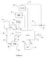
Figure 2 is a schematic diagram illustrating the hydrogen purity system of the present invention; -
Figure 3 is a schematic diagram illustrating an alternate embodiment hydrogen purity system of the present invention; -
Figure 4 is a schematic diagram illustrating an alternate embodiment hydrogen purity system with excess hydrogen storage of the present invention; -
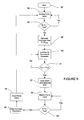
Figure 5 is a block flow diagram illustrating the method of operating the system ofFigure 2 ; -
Figure 6 is a block flow diagram illustrating the method of operating the system ofFigure 3 ; -
Figure 7 is a block flow diagram illustrating the method of operating the system ofFigure 4 . - As the demand for power by consumers has increased, electrical power producers have increasingly turned to larger generators to fulfill the needs of society. As the size of the generators increased, it became increasingly more difficult to maintain the generator at an appropriate operating temperature to prevent damage to the generator components. Smaller generators relied on air cooling to dissipate heat from the generator rotor windings. To improve heat transfer, generator manufacturers began to utilitize hydrogen gas as a transfer agent since the thermal conductivity of hydrogen is seven times that of air.
- The switch to hydrogen also yielded side benefits by reducing the windage losses in the generator due to hydrogen's lower density. As shown in
Figure 1 , the higher purity level of the hydrogen gas in the generator, the lower the windage losses. However, since the generator contains various components, such as seals which must be lubricated, contaminants such as water and oil become mixed with the gas reducing the purity levels. To compensate for these contaminants, operators utilized purifying systems, such as a heated regenerative dryer, which allowed removal of water from the generator without having to purge the generator of a costly gas. - In addition to contamination, operators must cope with hydrogen leaks which typically occur at the generators seals. As hydrogen escapes, the operator must add make-up hydrogen gas to the generator in order to maintain the heat transfer and low windage benefits. In a typical generator such as a GE Frame-7 generator, the loss of hydrogen and the amount of hydrogen can reach up to 20 - 40 cubic feet of hydrogen per hour.
- An exemplary embodiment of the present invention is shown in
Figure 2 . Thegenerator system 10 includes agenerator 12 which may be driven by any conventional means, such as a steam turbine (not shown). Thegenerator 12 produces electricity which is transmitted to theutility grid 14. The pressure inside the generator is monitored by apressure monitor 16 and the purity of the hydrogen gas inside the generator is monitored by amonitor 18. As will be described in more detail herein, the purity monitor may be of any suitable type capable, such as but not limited to a thermal conductivity analyzer or a vibrating element analyzer. - The
generator 12 also includes avent line 19 which connects to asolenoid valve 20. The outlet of thevalve 20 leads to a vent which allows the hydrogen gas to be properly dissipated into the atmosphere. As will be described in more detail herein, acommunications link 17 connects thepurity monitor 18 with thesolenoid valve 20. Ahydrogen generator 24 provides hydrogen gas to thegenerator 12 throughconduit 26. Alternatively, the a controller (not shown) in thegenerator 12 controls thesolenoid valve 20 to vent the hydrogen gas. - In the preferred embodiment, the hydrogen generator will include a water-fed electrochemical cell which is capable of disassociating reactant water into hydrogen and oxygen gas. Suitable reactant water is deionized, distilled water, which is continuously supplied from a
water source 28. The electrochemical cell will preferably be of a polymer electrode membrane (PEM) type. The electrochemical cell may also be any other suitable electrochemical cell such as, but not limited to, alkaline, phosphoric acid, or solid oxide based cells. Thehydrogen generator 24 may also be any non-electrochemical system capable of producing hydrogen gas such as, but not limited, a steam methane, or natural gas reformation. - An
output sensor 30 is incorporated into thehydrogen generator 24 to sense the differential pressure between the downstream in theconduit 26. Theoutput sensor 30 may be a pressure transducer that converts gas pressure within theconduit 26 to a voltage or current level indicative of the gas pressure. Output sensor may also be any other sensor suitable for sensing a qualitative or quantitative parameter of the gas and provide an electrical signal indicative of that parameter as an output. Such other sensors include, but are not limited to, a flow rate sensor, a mass flow sensor, and a differential pressure sensor. Optionally, afeedback signal 29 may be provided from the pressure monitor 18 to thehydrogen generator 24 -
Output sensor 30 interfaces with a controller (not shown) that is capable of converting the analog voltage or current level provided by thesensor 30 into a digital signal indicative of the sensed hydrogen pressure. The controller compares the sensed hydrogen pressure to a predetermined parameter for controlling the output of thehydrogen generator 24 as will be described in more detail herein. - An alternate embodiment of the electrical
power generating system 10 is shown inFigure 3 . In this embodiment, the purity monitor 18 is electrically coupled to theelectrolyzer 24 byline 32 to provide a control signal when the hydrogen gas purity level drops below a predetermined threshold. - Electrical power generators hold a large volume of hydrogen gas, typically at least 7,500 cubic feet. Consequently, at an event where the generator needs to be purged and filled with hydrogen gas, such as at startup, or after maintenance, the operator will need access to a large volume of hydrogen gas. Events such as startup or maintenance purging typically occur on an annual basis. Since a hydrogen generator capable of generating this volume of hydrogen in a short period of time would be greatly over-sized for daily operation. Accordingly, it is desirable to have a means for storing excess hydrogen gas generated by the
hydrogen generator 24. In the embodiment shown inFigure 4 , the hydrogen generator has afirst conduit 26 which provides hydrogen to thegenerator 12 as described herein above. Thehydrogen generator 24 further includes asecond conduit 34 and avalve 27 which fluidly couples the hydrogen generator to at least onestorage tank 40. Thesystem 10 may also optionally include asolenoid valve 36 and acompressor 38 coupled to theconduit 34. Anoptional pressure transducer 42 may be electrically coupled to thevalve 36 to terminate filling of thetank 40 once a desired pressure level is reached. The compressor may be any suitable type, such as but not limited to a metal hydride compressor, an electrochemical compressor, or a mechanical compressor. Thecompressor 38 is shown external to thehydrogen generator 24 for exemplary purposes, preferably, the compressor may be integrated with thehydrogen generator 24. Aconduit 46 fluidly couples thetank 40 with thegenerator 12. Avalve 48 controls flow from the tank to thegenerator 12. -
Figures 5 ,6 , and7 are flow diagrams depicting the operation of the generatingsystem 10. These methods may be included and executed in the controller application code in one or more of the individual components of thesystem 10, or may be embodied in a single central controller (not shown). These methods are embodied in computer instructions written to be executed by a microprocessor typically in the form of software. The software can be encoded in any language, including, but not limited to, assembly language, VHDL (Verilog Hardware Description Language), VHSIC HDL (Very High Speed IC Hardware Description Language), Fortran (formula translation), C, C++, Visual C++, Java, ALGOL (algorithmic language), BASIC (beginners all-purpose symbolic instruction code), visual BASIC, ActiveX, HTML (HyperText Markup Languarge), and any combination or derivative of at least one of the foregoing. Additionally, an operator can use an existing software application such as a spreadsheet or database and correlate various components enumerated in the algorithms. Furthermore, the software can be independent of other software or dependent upon other software, such as in the form of integrated software. - Referring to
Figures 2 and5 a electrical power generatingsystem control method 60 ofFigure 5 will now be described.Method 60 starts atblock 62 and proceeds to block 64. Atblock 64, the purity monitor 18 samples hydrogen from thegenerator 12 to determine a value Hpure indicative of the level of hydrogen purity in the sampled gas.Method 60 then proceeds to block 66, where the purity level Hpure is compared with a desired level Hpref. The parameter Hpref represents the purity level desired by the operator and allows the operator to balance efficiency requirements with hydrogen usage. Alternatively, the operator may choose to monitor the pressure level inside thegenerator 12 and purposes herein, the monitoring of pressure or purity may be used interchangeably. Typical values for Hpref are between 90% and 99% with a desired Hpref of 98%. A higher the value of Hpref will typically result in greater hydrogen usage. Of the answer to queryblock 66 is negative, themethod 60 returns to block 64 where the hydrogen gas is again sampled and measured. This loop continues generally untilmethod 60 is externally terminated or paused, or until the query ofblock 66 is answered affirmatively. - If the answer to the query of
block 66 is affirmative, either in the first instance or after one or more negative answers, themethod 60 proceeds to block 68 where a control signal is passed from purity monitor 18 to thevalve 20 causing thevalve 20 to open. The opening of thevalve 20 allows gas from thegenerator 12 to be vented to the atmosphere. - The
method 60 then proceeds on to block 70 to produce hydrogen gas. Generally, thehydrogen generator 24 will detect the pressure drop atsensor 30 that results from the venting of thegenerator 12 which occurred inblock 68. Typically, upon detection of this drop in pressure below the desired pressure Pdes thehydrogen generator 24 will initiate production of hydrogen gas which is transferred to thegenerator 12. - The
method 60 then continues on to block 72 where the gas from thegenerator 12 is sampled and the hydrogen purity measured.Method 60 then proceeds on to queryblock 74 where the Hpure is compared with a desired level Hpref. If the query answers affirmative, themethod 60 loops back to block 72 and continues to monitor the hydrogen purity IIpure in thegenerator 12. This loop continues generally untilmethod 60 is externally terminated or paused, or until the query ofblock 66 is answered affirmatively. - If the answer to the query in
block 74 is negative, this is indicative that the purity level of the hydrogen gas in the generator has reached a level desired by the operator. Themethod 60 then proceeds on to block 76 where a control signal is passed from the purity monitor 18 to thevalve 20. Thevalve 20 closes and the venting of gas from thegenerator 12 stops.Method 60 then proceeds on to block 78 where hydrogen production ceases. In the preferred embodiment, when thevalve 20 is closed, the pressure will rise in the generator. This pressure rise will be detected in thesensor 30, and when the pressure in the generator reaches the desired pressure Pdes thehydrogen generator 24 stops production of hydrogen gas. Typically, the desired pressure Pdes is between 30 psi and 75 psi.Method 60 then continues back to block 64 to start the process again. It will be appreciated thatmethod 60 is performed repetitively during the operation of thesystem 10. - Referring to
Figures 3 and6 , an alternate electrical power generation control method 80 ofFigure 6 will now be described. After starting atblock 82, method 80 proceeds to block 254 where the hydrogen purity level the Hpure of the gas in thegenerator 12 is sampled measured. Method 80 then proceeds to queryblock 86 where the parameter Hpure is compared with the desired purity level Hpref . If the query returns a negative response, the method 80 loops back to block 84 and the method continues until terminated or paused by the operator. - If the
query block 86 returns an affirmative response, the method 80 continues on to block 88. Inblock 86, purity monitor 18 sends a control signal to thehydrogen generator 24 which causes thehydrogen generator 24 to initiate hydrogen production at a predetermined flow rate and pressure Pdes. Typically, the desired pressure Pdes is between 30psi and 75 psi, with a preferred pressure of 45 psi. In the preferred embodiment, the desired pressure Pdes is greater than the relief pressure Prelief ofvalve 20. - After hydrogen gas production is initiated, the method 80 continues on to query
block 91 where Prelief and Pgen are introduced into the following query:
- Here, the parameter Pgen represents the pressure inside the
generator 12 and the parameter Prelief represents the pressure setting at which thevalve 20 will open allowing the gas from thegenerator 12 to vent to the atmosphere. If the query inbox 86 returns a negative, the method 80 loops back tobox 90 and hydrogen continues to be generated and provided to thegenerator 12. The method 80 continues until terminated or paused by the operator. - If the query in
box 91 returns an affirmative response, indicating that the pressure inside the generator has reaches a value greater than the relief setting on thevalve 20, the method 80 continues on tobox 92 and thevalve 20 is opened. The method continues on to monitor the hydrogen purity level Hpure inbox 93 and compare with the desired purity level inbox 94 in a similar manner as has been described herein above. - Once the purity of the hydrogen gas in the generator achieves the desired purity level, the method 80 continues on to block 96 where the purity monitor 18 transmits a control signal to the
hydrogen generator 24 causing the hydrogen generator to cease production of hydrogen gas. Once the hydrogen generator stops producing gas, the method 80 continues on tobox 98 where thevalve 20 will close once the pressure in the generator drops below the predetermined threshold. - Method 80 then continues back to block 84 to start the process again. It will be appreciated that method 80 is performed repetitively during the operation of the
system 10. - Referring to
Figures 4 and7 , an alternate electrical powergeneration control method 100 ofFigure 7 will now be described. After starting atblock 102,method 100 proceeds to block 104 where the hydrogen purity level the Hpure of the gas in thegenerator 12 is sampled measured.Method 100 then proceeds to query block 106 where the parameter Hpure is compared with the desired purity level Hpref . If the query returns a negative response, themethod 100 proceeds on to block 108 which opens thevalve 36 allowing hydrogen gas to flow from thehydrogen generator 24 towards thetank 40. Themethod 100 then optionally compresses the hydrogen gas inblock 110 and proceeds to filltank 40 inblock 112. - While the
tank 40 is filling, themethod 100 monitors the pressure Ptank in thetank 40. Thetank 40 will also have a maximum working pressure rating Pmax. Typically, thetank 40 will have a maximum pressure rating between 2000 psi and 10,000 psi, with a preferred rating of 2,400 psi.Method 100 proceeds to block 114 where Ptank and Pmax are introduced into the following query:
- If the query responds affirmatively, the
method 100proceeds query box 118 where the hydrogen purity level is compared to the desired level. If the query returns an affirmative response, which would indicate that the generator required replenishment of pure hydrogen gas. Themethod 100 then proceeds on to block 120 where thevalve 36 is closed and then ontoblock 122 where thevent valve 20 is opened and gas from thegenerator 12 is vented to the atmosphere.Method 100 then proceeds through blocks 128-134 to replenish the generator with hydrogen gas to the appropriate purity level in the same manner as was described herein above with respect tomethod 60 and blocks 72-78. - It should be appreciated that the process steps in blocks 128-134 may also be accomplished using the alternate method described with respect method 80. In addition, in applications where the
hydrogen generator 24 is continuously producing gas for thegenerator 12, it is within the contemplation of this invention that thehydrogen generator 24 provides hydrogen gas to both thetank 40 and thegenerator 12 simultaneously with preference being given to supplying thegenerator 12. - While the invention has been described with reference to a preferred embodiment, it will be understood by those skilled in the art that various changes may be made and equivalents may be substituted for elements thereof without departing from the scope of the invention. In addition, may modifications may be made to adapt a particular situation or material to the teachings of the invention without departing from the essential scope thereof. Therefore, it is intended that the invention not be limited to the particular embodiment disclosed as the best mode contemplated for carrying out this invention.
Claims (8)
- A method for maintaining hydrogen purity in an electrical generator (12), the method comprising: a) monitoring the purity of the hydrogen in the generator (12); b) generating a signal in response to said purity falling below a predetermined threshold; characterised by the further steps of c) adding hydrogen gas in response to said signal; d) venting hydrogen gas from said generator (12); and e) activating a hydrogen generator (24) in response to said purity signal.
- The method of claim 1 further comprising the step of continuing to add hydrogen gas and vent hydrogen from the generator (12) until the purity of the hydrogen in the generator (12) exceeds a predetermined threshold.
- The method of claim 1 further comprising the step of venting gas from said generator (12) if the pressure exceeds a predetermined threshold.
- The method of claim 3 further comprising the steps of providing a second purity signal in response to the purity in the generator (12) exceeding a predetermined threshold, and stopping production of hydrogen gas in response to said second purity signal.
- A system for maintaining hydrogen purity in an electrical generator (12), the system comprising: a hydrogen generator (24); an electrical generator (12) coupled to said hydrogen generator (24); a valve (20) coupled to said electrical generator (12), said valve (20) being configured to release hydrogen gas from said electrical generator (12) at a predetermined hydrogen gas pressure level; a purity monitor (18) operably coupled to said electrical generator (12) and said hydrogen generator (24), wherein said hydrogen generator (24) produces hydrogen gas at predetermined rate in response to a signal from said purity monitor (18).
- The system of claim 5 wherein said valve (20) releases hydrogen gas when the gas pressure in said electrical generator (12) exceeds 100 psi.
- The system of claim 5 wherein said hydrogen generator (24) is an electrochemical generator having at least one polymer electrode membrane.
- The system of claim 5 wherein said hydrogen generator (24) produces hydrogen gas by reformation of natural gas.
Applications Claiming Priority (2)
| Application Number | Priority Date | Filing Date | Title |
|---|---|---|---|
| US10/711,395 US7550113B2 (en) | 2004-09-16 | 2004-09-16 | System for maintaining hydrogen purity in electrical generators and method thereof |
| PCT/US2005/033361 WO2006034127A2 (en) | 2004-09-16 | 2005-09-16 | System for maintaining hydrogen purity in electrical generators and method thereof |
Publications (3)
| Publication Number | Publication Date |
|---|---|
| EP1789855A2 EP1789855A2 (en) | 2007-05-30 |
| EP1789855A4 EP1789855A4 (en) | 2010-03-31 |
| EP1789855B1 true EP1789855B1 (en) | 2014-01-22 |
Family
ID=36034194
Family Applications (1)
| Application Number | Title | Priority Date | Filing Date |
|---|---|---|---|
| EP05798194.6A Expired - Lifetime EP1789855B1 (en) | 2004-09-16 | 2005-09-16 | System for maintaining hydrogen purity in electrical generators and method thereof |
Country Status (6)
| Country | Link |
|---|---|
| US (2) | US7550113B2 (en) |
| EP (1) | EP1789855B1 (en) |
| JP (1) | JP2008514180A (en) |
| CN (1) | CN101006345B (en) |
| CA (1) | CA2574622A1 (en) |
| WO (1) | WO2006034127A2 (en) |
Families Citing this family (25)
| Publication number | Priority date | Publication date | Assignee | Title |
|---|---|---|---|---|
| US20060057727A1 (en) * | 2004-09-16 | 2006-03-16 | Speranza A J | System for monitoring the health of electrical generators and method thereof |
| US9783754B2 (en) * | 2005-05-20 | 2017-10-10 | Air Products And Chemical, Inc. | Methods for managing a product carrier |
| US20070243624A1 (en) * | 2006-04-12 | 2007-10-18 | Proton Energy Systems Inc. | Hydrogen emission reporting system and method thereof |
| US8080887B2 (en) * | 2008-09-19 | 2011-12-20 | Brad Radl | Closed loop control of hydrogen cooling of an electric power generator |
| US8128875B2 (en) * | 2010-02-26 | 2012-03-06 | General Electric Company | Hydrogen control system for electric generator |
| US8378535B2 (en) * | 2010-02-26 | 2013-02-19 | General Electric Company | Scavenging filter system for hydrogen-cooled dynamoelectric machines |
| US8768112B2 (en) * | 2010-10-22 | 2014-07-01 | General Electric Company | System having fiber optic purity sensor |
| JP5860696B2 (en) * | 2011-01-05 | 2016-02-16 | ゼネラル・エレクトリック・カンパニイ | Detection of generator seal leaks and seal oil contamination |
| GB2497787B (en) * | 2011-12-21 | 2019-06-26 | Intelligent Energy Ltd | Hydrogen quality monitor |
| JP5425956B2 (en) * | 2012-03-22 | 2014-02-26 | 中国電力株式会社 | Hydrogen gas supply system |
| US9677869B2 (en) * | 2012-12-05 | 2017-06-13 | Perimeter Medical Imaging, Inc. | System and method for generating a wide-field OCT image of a portion of a sample |
| CN103745062B (en) * | 2014-01-16 | 2017-07-14 | 广东电网公司电力科学研究院 | The repair method and system of a kind of generator hydrogen cooling system |
| GB2526287C (en) * | 2014-05-19 | 2023-02-08 | Intelligent Energy Ltd | Apparatus for determining reactant purity |
| US9975086B2 (en) | 2014-11-06 | 2018-05-22 | Environment One Corporation | Methods and systems for drying hydrogen gas used in hydrogen-cooled generators |
| US10141816B2 (en) * | 2015-01-21 | 2018-11-27 | Siemens Energy, Inc. | Method of achieving variable performance of an electric generator |
| CN104726892B (en) * | 2015-03-25 | 2017-06-16 | 首钢京唐钢铁联合有限责任公司 | Device and method for recycling hydrogen and oxygen produced by electrolyzing water |
| CN104865928B (en) * | 2015-03-28 | 2018-12-21 | 刘晓冰 | The monitoring system and its method of a kind of electric generator inner cooling but medium |
| EP3407474A1 (en) * | 2017-05-22 | 2018-11-28 | General Electric Technology GmbH | Multiple mode hydrogen release system and method for a hydrogen cooled generator |
| CN108828135A (en) * | 2018-03-09 | 2018-11-16 | 惠州大亚湾伊科思新材料科技发展有限公司 | A method of saving nine hydrogenation plant hydrogen gas consumption of carbon |
| CN108728862A (en) * | 2018-06-30 | 2018-11-02 | 神华国华广投(柳州)发电有限责任公司 | A kind of method that online hydrogen making machine is arranged in hydrogen station |
| CN110783606B (en) * | 2019-09-24 | 2020-12-22 | 潍柴动力股份有限公司 | Method and device for detecting quality of fuel hydrogen and hydrogen fuel cell engine |
| CN113408104B (en) * | 2021-05-24 | 2022-08-19 | 中核核电运行管理有限公司 | Method and device for calculating real-time hydrogen leakage rate of generator |
| CN113803638B (en) * | 2021-07-30 | 2023-07-07 | 华电电力科学研究院有限公司 | Intelligent generator hydrogen cooling system and control method |
| US12473838B2 (en) | 2021-10-26 | 2025-11-18 | Marine Dolphin Enterprises, LLC | Apparatus and method for maintaining gas pressure in an electrolyzer using an electric generator configured to capture kinetic energy of electrolysis products |
| CN116221618B (en) * | 2023-03-02 | 2024-09-27 | 华能山东发电有限公司白杨河发电厂 | Hydrogen supplementing method for generator |
Family Cites Families (23)
| Publication number | Priority date | Publication date | Assignee | Title |
|---|---|---|---|---|
| GB270315A (en) | 1926-04-30 | 1928-07-30 | Vickers Electrical Co Ltd | Improvements in or relating to enclosed dynamo-electric machines which are cooled by a circulation of hydrogen |
| US4029951A (en) * | 1975-10-21 | 1977-06-14 | Westinghouse Electric Corporation | Turbine power plant automatic control system |
| US4531070A (en) * | 1982-11-16 | 1985-07-23 | Westinghouse Electric Corp. | Turbine generator hydrogen filtration system |
| JPS59216441A (en) | 1983-05-20 | 1984-12-06 | Toshiba Corp | Hydrogen-cooled turbine generator |
| JPS60145408A (en) | 1984-01-09 | 1985-07-31 | Toshiba Corp | Combined cycle electric power plant |
| JPS61231849A (en) | 1985-04-04 | 1986-10-16 | Mitsubishi Heavy Ind Ltd | Cooling system of turbine generator |
| US4792911A (en) | 1986-01-17 | 1988-12-20 | Westinghouse Electric Corp. | Diagnostic apparatus for an electric generator seal oil system |
| US4891629A (en) * | 1988-05-16 | 1990-01-02 | General Electric Company | Binary gas analyzer instrument and analysis method |
| US5088315A (en) * | 1990-09-12 | 1992-02-18 | Johnson Walter A | Gas purity analyzer and method |
| US5510201A (en) * | 1992-04-24 | 1996-04-23 | H Power Corporation | Method of operating a fuel cell wherein hydrogen is generated by providing iron in situ |
| CZ108595A3 (en) * | 1992-11-05 | 1995-08-16 | Siemens Ag | Device for exhausting waste gas containing hydrogen and residual gas from an electric machine being filled with nitrogen, and use thereof |
| JPH07231610A (en) | 1994-02-18 | 1995-08-29 | Iwatani Internatl Corp | Gas cooling method for large capacity generator and mixed gas for cooling |
| US6837887B2 (en) | 1995-06-07 | 2005-01-04 | Arthrocare Corporation | Articulated electrosurgical probe and methods |
| DE19528090C1 (en) * | 1995-07-31 | 1997-01-23 | Siemens Ag | Method and device for rapid pressure reduction in a system, especially in a hydrogen-cooled generator |
| US5929324A (en) | 1997-08-08 | 1999-07-27 | Taiwan Semiconductor Manufacturing Co., Ltd. | Apparatus for detecting leakage in a gas reactor |
| JP2000209812A (en) * | 1999-01-18 | 2000-07-28 | Hitachi Ltd | Hydrogen gas replacement device for cooling of rotating electric machines |
| US6305442B1 (en) * | 1999-11-06 | 2001-10-23 | Energy Conversion Devices, Inc. | Hydrogen-based ecosystem |
| US6524464B2 (en) | 2001-04-25 | 2003-02-25 | Proton Energy Systems, Inc. | Fan flow sensor for hydrogen generating proton exchange member electrolysis cell |
| EP1303028B1 (en) | 2001-10-15 | 2006-12-13 | Siemens Aktiengesellschaft | System for supplying a generator with hydrogen |
| US6959585B2 (en) * | 2001-11-14 | 2005-11-01 | Environment One Corporation | Skids, modules, and modular system for monitoring hydrogen-cooled generators |
| EP1473386A4 (en) * | 2002-01-29 | 2005-04-06 | Mitsubishi Corp | APPARATUS FOR PRODUCING HIGH PRESSURE HYDROGEN AND PROCESS FOR PRODUCING THE SAME |
| US6893755B2 (en) * | 2002-10-28 | 2005-05-17 | Cellex Power Products, Inc. | Method and system for controlling the operation of a hydrogen generator and a fuel cell |
| US20060057727A1 (en) * | 2004-09-16 | 2006-03-16 | Speranza A J | System for monitoring the health of electrical generators and method thereof |
-
2004
- 2004-09-16 US US10/711,395 patent/US7550113B2/en not_active Expired - Lifetime
-
2005
- 2005-09-16 CN CN2005800283955A patent/CN101006345B/en not_active Expired - Fee Related
- 2005-09-16 CA CA002574622A patent/CA2574622A1/en not_active Abandoned
- 2005-09-16 JP JP2007532556A patent/JP2008514180A/en active Pending
- 2005-09-16 EP EP05798194.6A patent/EP1789855B1/en not_active Expired - Lifetime
- 2005-09-16 WO PCT/US2005/033361 patent/WO2006034127A2/en not_active Ceased
-
2009
- 2009-05-08 US US12/463,105 patent/US7879613B2/en not_active Expired - Lifetime
Also Published As
| Publication number | Publication date |
|---|---|
| CN101006345B (en) | 2012-02-01 |
| CN101006345A (en) | 2007-07-25 |
| US7879613B2 (en) | 2011-02-01 |
| JP2008514180A (en) | 2008-05-01 |
| CA2574622A1 (en) | 2006-03-30 |
| US20060057034A1 (en) | 2006-03-16 |
| WO2006034127A3 (en) | 2006-12-07 |
| EP1789855A2 (en) | 2007-05-30 |
| US20090211920A1 (en) | 2009-08-27 |
| US7550113B2 (en) | 2009-06-23 |
| WO2006034127A2 (en) | 2006-03-30 |
| EP1789855A4 (en) | 2010-03-31 |
Similar Documents
| Publication | Publication Date | Title |
|---|---|---|
| US7879613B2 (en) | System for maintaining hydrogen purity in electrical generators and method thereof | |
| US7552622B2 (en) | System for monitoring the health of electrical generators and method thereof | |
| KR100456198B1 (en) | Hydrogen fuel replenishment process and system | |
| EP1653148B1 (en) | Gas supply system | |
| US20040023083A1 (en) | Device and method for controlling fuel cell system | |
| EP1331289A1 (en) | System and method for refueling a hydrogen vessel | |
| US20030090164A1 (en) | Skids, modules, and modular system for monitoring hydrogen-cooled generators | |
| US8246796B2 (en) | Fuel cell recharger | |
| JP2009123612A (en) | FUEL CELL SYSTEM AND CONTROL METHOD FOR FUEL CELL SYSTEM | |
| EP1181398B1 (en) | Pressure control system in a water electrolytic cell | |
| EP2132819B1 (en) | Fuel cell system | |
| JPH0785883A (en) | Abnormality detection device and abnormal time control device | |
| Fujitani et al. | Development of hydrogen-absorbing rare earth-Ni alloys for a− 20° C refrigeration system | |
| CA2206952C (en) | Hydrogen management system for metal/air fuel cell | |
| JP3169050B2 (en) | Hydrogen / oxygen generator and operating method thereof | |
| CA2370026C (en) | Hydrogen fuel replenishment process and system | |
| CN119572928A (en) | A hydrogen filling system | |
| JPH04267067A (en) | Liquid fuel evaporator for fuel cell generating device | |
| JP2000058094A (en) | Fuel cell power generator |
Legal Events
| Date | Code | Title | Description |
|---|---|---|---|
| PUAI | Public reference made under article 153(3) epc to a published international application that has entered the european phase |
Free format text: ORIGINAL CODE: 0009012 |
|
| 17P | Request for examination filed |
Effective date: 20070206 |
|
| AK | Designated contracting states |
Kind code of ref document: A2 Designated state(s): AT BE BG CH CY CZ DE DK EE ES FI FR GB GR HU IE IS IT LI LT LU LV MC NL PL PT RO SE SI SK TR |
|
| AX | Request for extension of the european patent |
Extension state: AL BA HR MK YU |
|
| DAX | Request for extension of the european patent (deleted) | ||
| A4 | Supplementary search report drawn up and despatched |
Effective date: 20100301 |
|
| 17Q | First examination report despatched |
Effective date: 20100608 |
|
| GRAP | Despatch of communication of intention to grant a patent |
Free format text: ORIGINAL CODE: EPIDOSNIGR1 |
|
| INTG | Intention to grant announced |
Effective date: 20130426 |
|
| RIC1 | Information provided on ipc code assigned before grant |
Ipc: H02K 9/26 20060101ALN20130412BHEP Ipc: G05D 21/02 20060101ALI20130412BHEP Ipc: G05B 1/00 20060101AFI20130412BHEP Ipc: H02K 9/24 20060101ALN20130412BHEP |
|
| RIN1 | Information on inventor provided before grant (corrected) |
Inventor name: GUDINO, LUISA Inventor name: SPERANZA, A. JOHN |
|
| GRAS | Grant fee paid |
Free format text: ORIGINAL CODE: EPIDOSNIGR3 |
|
| GRAA | (expected) grant |
Free format text: ORIGINAL CODE: 0009210 |
|
| AK | Designated contracting states |
Kind code of ref document: B1 Designated state(s): AT BE BG CH CY CZ DE DK EE ES FI FR GB GR HU IE IS IT LI LT LU LV MC NL PL PT RO SE SI SK TR |
|
| REG | Reference to a national code |
Ref country code: GB Ref legal event code: FG4D |
|
| REG | Reference to a national code |
Ref country code: CH Ref legal event code: EP |
|
| REG | Reference to a national code |
Ref country code: AT Ref legal event code: REF Ref document number: 651065 Country of ref document: AT Kind code of ref document: T Effective date: 20140215 |
|
| REG | Reference to a national code |
Ref country code: IE Ref legal event code: FG4D |
|
| REG | Reference to a national code |
Ref country code: DE Ref legal event code: R096 Ref document number: 602005042581 Country of ref document: DE Effective date: 20140306 |
|
| REG | Reference to a national code |
Ref country code: NL Ref legal event code: VDEP Effective date: 20140122 |
|
| REG | Reference to a national code |
Ref country code: AT Ref legal event code: MK05 Ref document number: 651065 Country of ref document: AT Kind code of ref document: T Effective date: 20140122 |
|
| REG | Reference to a national code |
Ref country code: LT Ref legal event code: MG4D |
|
| PG25 | Lapsed in a contracting state [announced via postgrant information from national office to epo] |
Ref country code: IS Free format text: LAPSE BECAUSE OF FAILURE TO SUBMIT A TRANSLATION OF THE DESCRIPTION OR TO PAY THE FEE WITHIN THE PRESCRIBED TIME-LIMIT Effective date: 20140522 Ref country code: LT Free format text: LAPSE BECAUSE OF FAILURE TO SUBMIT A TRANSLATION OF THE DESCRIPTION OR TO PAY THE FEE WITHIN THE PRESCRIBED TIME-LIMIT Effective date: 20140122 |
|
| PG25 | Lapsed in a contracting state [announced via postgrant information from national office to epo] |
Ref country code: AT Free format text: LAPSE BECAUSE OF FAILURE TO SUBMIT A TRANSLATION OF THE DESCRIPTION OR TO PAY THE FEE WITHIN THE PRESCRIBED TIME-LIMIT Effective date: 20140122 Ref country code: CY Free format text: LAPSE BECAUSE OF FAILURE TO SUBMIT A TRANSLATION OF THE DESCRIPTION OR TO PAY THE FEE WITHIN THE PRESCRIBED TIME-LIMIT Effective date: 20140122 Ref country code: NL Free format text: LAPSE BECAUSE OF FAILURE TO SUBMIT A TRANSLATION OF THE DESCRIPTION OR TO PAY THE FEE WITHIN THE PRESCRIBED TIME-LIMIT Effective date: 20140122 Ref country code: SE Free format text: LAPSE BECAUSE OF FAILURE TO SUBMIT A TRANSLATION OF THE DESCRIPTION OR TO PAY THE FEE WITHIN THE PRESCRIBED TIME-LIMIT Effective date: 20140122 Ref country code: PT Free format text: LAPSE BECAUSE OF FAILURE TO SUBMIT A TRANSLATION OF THE DESCRIPTION OR TO PAY THE FEE WITHIN THE PRESCRIBED TIME-LIMIT Effective date: 20140522 Ref country code: ES Free format text: LAPSE BECAUSE OF FAILURE TO SUBMIT A TRANSLATION OF THE DESCRIPTION OR TO PAY THE FEE WITHIN THE PRESCRIBED TIME-LIMIT Effective date: 20140122 Ref country code: FI Free format text: LAPSE BECAUSE OF FAILURE TO SUBMIT A TRANSLATION OF THE DESCRIPTION OR TO PAY THE FEE WITHIN THE PRESCRIBED TIME-LIMIT Effective date: 20140122 |
|
| PG25 | Lapsed in a contracting state [announced via postgrant information from national office to epo] |
Ref country code: BE Free format text: LAPSE BECAUSE OF FAILURE TO SUBMIT A TRANSLATION OF THE DESCRIPTION OR TO PAY THE FEE WITHIN THE PRESCRIBED TIME-LIMIT Effective date: 20140122 Ref country code: LV Free format text: LAPSE BECAUSE OF FAILURE TO SUBMIT A TRANSLATION OF THE DESCRIPTION OR TO PAY THE FEE WITHIN THE PRESCRIBED TIME-LIMIT Effective date: 20140122 |
|
| REG | Reference to a national code |
Ref country code: DE Ref legal event code: R097 Ref document number: 602005042581 Country of ref document: DE |
|
| PG25 | Lapsed in a contracting state [announced via postgrant information from national office to epo] |
Ref country code: EE Free format text: LAPSE BECAUSE OF FAILURE TO SUBMIT A TRANSLATION OF THE DESCRIPTION OR TO PAY THE FEE WITHIN THE PRESCRIBED TIME-LIMIT Effective date: 20140122 Ref country code: DK Free format text: LAPSE BECAUSE OF FAILURE TO SUBMIT A TRANSLATION OF THE DESCRIPTION OR TO PAY THE FEE WITHIN THE PRESCRIBED TIME-LIMIT Effective date: 20140122 Ref country code: CZ Free format text: LAPSE BECAUSE OF FAILURE TO SUBMIT A TRANSLATION OF THE DESCRIPTION OR TO PAY THE FEE WITHIN THE PRESCRIBED TIME-LIMIT Effective date: 20140122 Ref country code: RO Free format text: LAPSE BECAUSE OF FAILURE TO SUBMIT A TRANSLATION OF THE DESCRIPTION OR TO PAY THE FEE WITHIN THE PRESCRIBED TIME-LIMIT Effective date: 20140122 |
|
| PG25 | Lapsed in a contracting state [announced via postgrant information from national office to epo] |
Ref country code: SK Free format text: LAPSE BECAUSE OF FAILURE TO SUBMIT A TRANSLATION OF THE DESCRIPTION OR TO PAY THE FEE WITHIN THE PRESCRIBED TIME-LIMIT Effective date: 20140122 Ref country code: PL Free format text: LAPSE BECAUSE OF FAILURE TO SUBMIT A TRANSLATION OF THE DESCRIPTION OR TO PAY THE FEE WITHIN THE PRESCRIBED TIME-LIMIT Effective date: 20140122 |
|
| PLBE | No opposition filed within time limit |
Free format text: ORIGINAL CODE: 0009261 |
|
| STAA | Information on the status of an ep patent application or granted ep patent |
Free format text: STATUS: NO OPPOSITION FILED WITHIN TIME LIMIT |
|
| 26N | No opposition filed |
Effective date: 20141023 |
|
| REG | Reference to a national code |
Ref country code: DE Ref legal event code: R097 Ref document number: 602005042581 Country of ref document: DE Effective date: 20141023 |
|
| PG25 | Lapsed in a contracting state [announced via postgrant information from national office to epo] |
Ref country code: LU Free format text: LAPSE BECAUSE OF FAILURE TO SUBMIT A TRANSLATION OF THE DESCRIPTION OR TO PAY THE FEE WITHIN THE PRESCRIBED TIME-LIMIT Effective date: 20140916 Ref country code: MC Free format text: LAPSE BECAUSE OF FAILURE TO SUBMIT A TRANSLATION OF THE DESCRIPTION OR TO PAY THE FEE WITHIN THE PRESCRIBED TIME-LIMIT Effective date: 20140122 |
|
| REG | Reference to a national code |
Ref country code: CH Ref legal event code: PL |
|
| GBPC | Gb: european patent ceased through non-payment of renewal fee |
Effective date: 20140916 |
|
| PG25 | Lapsed in a contracting state [announced via postgrant information from national office to epo] |
Ref country code: SI Free format text: LAPSE BECAUSE OF FAILURE TO SUBMIT A TRANSLATION OF THE DESCRIPTION OR TO PAY THE FEE WITHIN THE PRESCRIBED TIME-LIMIT Effective date: 20140122 |
|
| REG | Reference to a national code |
Ref country code: IE Ref legal event code: MM4A |
|
| REG | Reference to a national code |
Ref country code: FR Ref legal event code: ST Effective date: 20150529 |
|
| PG25 | Lapsed in a contracting state [announced via postgrant information from national office to epo] |
Ref country code: GB Free format text: LAPSE BECAUSE OF NON-PAYMENT OF DUE FEES Effective date: 20140916 Ref country code: LI Free format text: LAPSE BECAUSE OF NON-PAYMENT OF DUE FEES Effective date: 20140930 Ref country code: CH Free format text: LAPSE BECAUSE OF NON-PAYMENT OF DUE FEES Effective date: 20140930 |
|
| PG25 | Lapsed in a contracting state [announced via postgrant information from national office to epo] |
Ref country code: IE Free format text: LAPSE BECAUSE OF NON-PAYMENT OF DUE FEES Effective date: 20140916 Ref country code: FR Free format text: LAPSE BECAUSE OF NON-PAYMENT OF DUE FEES Effective date: 20140930 |
|
| PGFP | Annual fee paid to national office [announced via postgrant information from national office to epo] |
Ref country code: DE Payment date: 20150908 Year of fee payment: 11 |
|
| PG25 | Lapsed in a contracting state [announced via postgrant information from national office to epo] |
Ref country code: BG Free format text: LAPSE BECAUSE OF FAILURE TO SUBMIT A TRANSLATION OF THE DESCRIPTION OR TO PAY THE FEE WITHIN THE PRESCRIBED TIME-LIMIT Effective date: 20140122 |
|
| PG25 | Lapsed in a contracting state [announced via postgrant information from national office to epo] |
Ref country code: GR Free format text: LAPSE BECAUSE OF FAILURE TO SUBMIT A TRANSLATION OF THE DESCRIPTION OR TO PAY THE FEE WITHIN THE PRESCRIBED TIME-LIMIT Effective date: 20140423 Ref country code: IT Free format text: LAPSE BECAUSE OF FAILURE TO SUBMIT A TRANSLATION OF THE DESCRIPTION OR TO PAY THE FEE WITHIN THE PRESCRIBED TIME-LIMIT Effective date: 20140122 |
|
| PG25 | Lapsed in a contracting state [announced via postgrant information from national office to epo] |
Ref country code: TR Free format text: LAPSE BECAUSE OF FAILURE TO SUBMIT A TRANSLATION OF THE DESCRIPTION OR TO PAY THE FEE WITHIN THE PRESCRIBED TIME-LIMIT Effective date: 20140122 Ref country code: HU Free format text: LAPSE BECAUSE OF FAILURE TO SUBMIT A TRANSLATION OF THE DESCRIPTION OR TO PAY THE FEE WITHIN THE PRESCRIBED TIME-LIMIT; INVALID AB INITIO Effective date: 20050916 |
|
| REG | Reference to a national code |
Ref country code: DE Ref legal event code: R119 Ref document number: 602005042581 Country of ref document: DE |
|
| PG25 | Lapsed in a contracting state [announced via postgrant information from national office to epo] |
Ref country code: DE Free format text: LAPSE BECAUSE OF NON-PAYMENT OF DUE FEES Effective date: 20170401 |