EP1788664A1 - Flat antenna - Google Patents
Flat antenna Download PDFInfo
- Publication number
- EP1788664A1 EP1788664A1 EP04766898A EP04766898A EP1788664A1 EP 1788664 A1 EP1788664 A1 EP 1788664A1 EP 04766898 A EP04766898 A EP 04766898A EP 04766898 A EP04766898 A EP 04766898A EP 1788664 A1 EP1788664 A1 EP 1788664A1
- Authority
- EP
- European Patent Office
- Prior art keywords
- antenna according
- previous
- antenna
- corrugations
- slot
- Prior art date
- Legal status (The legal status is an assumption and is not a legal conclusion. Google has not performed a legal analysis and makes no representation as to the accuracy of the status listed.)
- Granted
Links
Images










Classifications
-
- H—ELECTRICITY
- H01—ELECTRIC ELEMENTS
- H01Q—ANTENNAS, i.e. RADIO AERIALS
- H01Q13/00—Waveguide horns or mouths; Slot antennas; Leaky-waveguide antennas; Equivalent structures causing radiation along the transmission path of a guided wave
- H01Q13/10—Resonant slot antennas
-
- H—ELECTRICITY
- H01—ELECTRIC ELEMENTS
- H01Q—ANTENNAS, i.e. RADIO AERIALS
- H01Q19/00—Combinations of primary active antenna elements and units with secondary devices, e.g. with quasi-optical devices, for giving the antenna a desired directional characteristic
Definitions
- the present invention relates to antennas with a planar profile coupled to waveguides and particularly to completely planar antennas, applicable in mobile telephony, radars and space communications.
- Said planar antennas base their operation on the transmission of electromagnetic waves, mainly in the range of microwaves and millimetric waves, through a thin opening of a height that is less than the wavelength, having corrugations in the area surrounding said opening, such that maximized wave transmission as well as the collimation thereof in a defined direction towards leaky waves by means of a resonant coupling mechanism are achieved.
- Antennas are known that are based on microwave and millimetric planar circuit technology; for example European patent application EP-0910134-A discloses a planar antenna for microwave transmission.
- the antenna comprises at least one printed circuit and has active elements such as transmission lines and radiation elements.
- the antenna is made up of a plate and a box joined together and between which the antenna's printed circuit, a polarizer and a ground plate are arranged, all the elements being separated from one another by means of foam spacers.
- a planar antenna in addition to not having the same structure and composition as the antenna object of the present invention, its operation is different and does not allow easy coupling of the waves from a waveguide to the antenna.
- US parent number 6,639,566-B discloses a non-planar antenna based on waveguide horns for producing two polarized orthogonal signals. It consists of two separated parallel conductive plates for defining an internal opening for microwave signal transmission. It also has extensions coupled to the edges of the plates such that the openings in the extensions are directed towards the reflective surfaces of the antenna. A waveguide provides microwave signals, the power densities of which grow narrower due to the corrugated surface of the extensions.
- This patent is a background document in the field of antennas but the main difference with the antenna herein proposed is the different non-planar structure thereof, which prevents its application in the same conditions as the antenna object of the present invention.
- International application WO-03019245-A discloses an apparatus for optical transmission with control of divergence and direction of light waves from at least one opening.
- Said apparatus comprises: light insensitive surface with at least one opening, a periodic or almost periodic topography on its surface comprising one or several features associated to said opening in which the light emerging from said opening interacts with surface waves on said surface, providing control over the direction and optical divergence of the emitted light.
- the main difference between this document and the planar antenna herein proposed is that despite describing a similar operation, it does not apply, nor does it suggest applying, the transmission of waves that are different to the optical wave range, and therefore it does not mention its application in the field of antennas either. Nor does it describe guiding the waves by means of t.he use of resonant couplings to improve the wave transmission. And lastly, nor does it mention the occurrence of transverse modes associated to the thin width of the slot.
- the present invention describes an antenna with a planar profile which, by making use of the physical surface wave excitation mechanism on a corrugated structure and its focalization by means of a slot made on said surface, allows reducing the antenna plate size and operating with microwaves or millimetric waves propagating in free space given that it makes the handling thereof simpler and easier.
- An object of the present invention is to obtain low profile, miniaturized planar antennas operating directly with guided waves, whether in a wire, a waveguide, a printed or monolithic circuit, etc., and allowing their emission and reception by making use of the previously described physical mechanism
- the proposed antenna consists of a waveguide coupled to the radiated wave by means of a resonant slot made in a metallic plate having several corrugations. Radiation occurs upon transferring the power of the guided waves by means of resonant coupling towards leaky waves, i.e. those guided waves that allow emitting radiation simultaneously, supported by the corrugated plate.
- a preferred embodiment consists of an antenna with a waveguide coupled by longitudinal resonance, i.e. by means of the thickness of the metallic plate separating the inside of the guide from free space. Only one corrugation is included on the metallic plate for the purpose of minimizing structuraL dimensions.
- Another embodiment consists of a planar antenna with a larger number of corrugations such that despite increasing the dimensions, better and greater focalization is obtained.
- the resulting wavelength is high, and therefore a compact design is unfeasible, though for millimetric wave frequencies, the described design is suitable since the thickness of the metallic plate is approximately a few millimeters.
- planar antennas in the microwave range for mobile communications it is necessary to reduce the thickness of the metal, preserving the radiation features intact, and to that end the slot is made to resonate in its transverse dimension, directly related with the slot width, rather than longitudinally.
- Another embodiment allows the design of a planar antenna with at least two pairs of corrugations, with the capacity to operate in two independent frequency bands, taking advantage of the fact that two independent resonances, longitudinal resonance and transverse resonance, can be excited in the slot. It is also possible to obtain the focus of the waves at different frequencies by means of controlling corrugation distance and depth.
- This construction allows obtaining a dual-band antenna the resonance frequencies of which can be fixed completely independently from one another by means of controlling central slot width and thickness.
- the gain increase is achieved by means of placing corrugations on the sides, each one of these corrugations being sensitive only to its design frequency whereas it is transparent for the other resonance.
- Another embodiment includes, inside the cavity formed by the corrugations, a low loss dielectric material and suitable relative dielectric permittivity, such that it allows reducing antenna plate thickness. This embodiment allows making ultraplanar antennas.
- an antenna is available without waveguide feed, consisting of a slot antenna on a high-frequency printed circuit board.
- resonance of the slot is transversal, such as that previously described for reducing the thickness, and is surrounded by corrugated metallic plates, these being filled with a high dielectric permittivity substrate.
- another embodiment consists of an antenna using concentric corrugations around the slot with transverse and longitudinal resonances, respectively.
- Figure 1 shows a diagram of an antenna object of the present application consisting of a slot surrounded by an indefinite number of corrugations on either of its sides and arranged on a metallic plate.
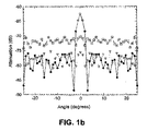
- the performance of said antenna with regard to collimation and transmission in the E-plane can be observed in Figure 1b.
- the comparison between the E-plane radiation pattern for the case of the absence of corrugations can be observed as a dotted line with inverted triangles, whereas for the case in which the corrugations are opposite to the wave source, it is represented as a dashed line with squares, and finally for the case in which the corrugations are on the opposite side, it appears as a dashed line with black dots. This is the case in which collimation of the emitted radiation occurs..
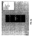
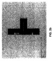
- Figures 2a and 2b detail a planar antenna with a corrugation on each side of the slot and which resonates longitudinally.
- Figure 2a shows the radiating transverse side, in which the length of the metallic plate L, its width a, which may coincide with the outer width of the feed waveguide, the width of the slot w, its height h, the distance of the corrugations to the axis of horizontal symmetry of the antenna d, and the height of said corrugations s, are detailed.
- Figure 2b shows a longitudinal section of the antenna with the thickness E of the metallic plate, the outer height of the feed waveguide b, the depth of the corrugations p and their thickness s.
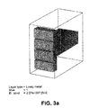
- this antenna consists of a waveguide coupled by longitudinal resonance, i.e. by means of the thickness of the metallic plate separating the inside of the guide from free space, as is shown in Figure 3a.
- a corrugation has been included on each side of the slot on the metallic plate in this embodiment. Since the slot has a half-wavelength depth and acts as a Babry-Perot resonator in its fundamental resonance, a power coupling exists as shown in Figure 3b. Said outer corrugations exert only a collimating effort on the diffracted power in the form of a surface wave on the back side..
- the resulting wavelength is high, which makes a compact design unfeasible, the design being appropriate for frequencies in the millimetric wave range given that the thickness of the metal, of the antenna is about a few millimeters Therefore, for application in the microwave range it is necessary to reduce the thickness of the metal, keeping the radiation features intact, achieving a different resonance at the working frequency and thus not being obliged to maintain a minimum thickness of the metallic structure.
- the slot is made to resonate in the transverse direction rather than to resonate longitudinally, said transverse resonance being directly related to the width of the slot, as can be seen in Figures 3c and 3d.
- Figure 3e shows the response in frequencies and in said figure two resonances are observed, one corresponding to the transverse resonance associated to the width of the slot, and the other one, which occurs at a higher frequency, is the longitudinal resonance associated to the thickness of the slot. This allows the antenna to work in two frequency bands, being necessary to adjust the corrugations to the chosen band.
- Figures 3f and 3g equivalent to the three-dimensional radiation patterns for an isolated slot and another slot with corrugations, respectively, allow comparing the radiations of both.
- An isotropic radiation pattern is obtained for the case of a slot without corrugations (3f) whereas a collimated radiation pattern is observed for the case in which the corrugations have been provided (3g).
- the details of said patterns in the E and H planes are also shown in Figures 3h and 3i, in polar coordinate format, for the case with the presence of corrugations
- the gain of the antenna object of the invention has also been compared in frequency with a considerably larger horn antenna, as can be seen in Figure 31.
- Figure 3m finally shows different manufactured designs demonstrating the possibility of making intrinsically planar and compact models.
- FIG. 4a shows the embodiment example shown in Figures 4a and 4b, obtaining considerable improvement in collimation, as can be seen in the three-dimensional far-field radiation pattern of Figure 4c.
- Figure 4d shows the three-dimensional far-field radiation pattern of the antenna of Figure 4b, thus demonstrating the possibility of obtaining asymmetrical collimation by means of the use of an asymmetrical corrugated structure, i.e. with corrugations only on one of the sides of the slot.
- figure 5a shows a planar antenna such as the one previously described in which additional corrugations have been introduced, specifically an additional corrugation one each side of the slot for the purpose of achieving focalization at another frequency such that the response in frequency is barely affected by the introduction of said additional corrugations.
- the current distributions for the two working frequencies are represented in Figures 5b and 5c.
- planar antenna which prevents feeding the antenna with a waveguide, allowing the application of planar antennas to planar and monolithic circuits by means of a completely planar design on a microwave substrate with corrugations excavated on the substrate and subsequent metallization, being possible to include via-holes facilitating connection between plates.
- FIG. 7a It is also possible to cany out a planar antenna design by using concentric corrugations around the slot with transverse and longitudinal resonance, as can be seen in Figure 7a.
- Figure 7b shows the response in frequencies, two resonances being observed corresponding to the transverse and longitudinal modes.
- the collimating effect of this antenna is much more pronounced than the previous designs, as can be seen in Figures 7c to 7e, in which the simulations of the three. dimensional E-plane (7d) and H-piane (7e) fax-field radiation pattern are represented.
- the simulations have been confirmed by the measurements carried out, as can be seen in Figures 7f and 7g, for the far-field radiation pattern for the E and H planes, respectively, represented in Cartesian coordinates.
- the gain of the antenna object of the invention has also been compared in frequency with a horn antenna of evidently larger dimensions, as can be seen in Figure 7h.
- Figure 7i finally shows a manufactured design of this antenna.
- planar structure of the previously described antennas can be used without a connection to a waveguide or to a circuit, simply as a selective surface receiving the waves in free space and allowing those which have a given frequency and given angle of incidence pass. Any of the previously described embodiments can be applied to this selective surface,
Landscapes
- Waveguide Aerials (AREA)
- Diaphragms For Electromechanical Transducers (AREA)
- Superconductors And Manufacturing Methods Therefor (AREA)
- Pyridine Compounds (AREA)
Abstract
Description
- The present invention relates to antennas with a planar profile coupled to waveguides and particularly to completely planar antennas, applicable in mobile telephony, radars and space communications. Said planar antennas base their operation on the transmission of electromagnetic waves, mainly in the range of microwaves and millimetric waves, through a thin opening of a height that is less than the wavelength, having corrugations in the area surrounding said opening, such that maximized wave transmission as well as the collimation thereof in a defined direction towards leaky waves by means of a resonant coupling mechanism are achieved.
- There are different antennas in the state of the art with different shapes and working modes the designs of which are usually aimed at a specific application, such as space communications, telephony, television and radar applications, among others.
- Antennas are known that are based on microwave and millimetric planar circuit technology; for example
European patent application EP-0910134-A discloses a planar antenna for microwave transmission. The antenna comprises at least one printed circuit and has active elements such as transmission lines and radiation elements. The antenna is made up of a plate and a box joined together and between which the antenna's printed circuit, a polarizer and a ground plate are arranged, all the elements being separated from one another by means of foam spacers. Despite being a planar antenna, in addition to not having the same structure and composition as the antenna object of the present invention, its operation is different and does not allow easy coupling of the waves from a waveguide to the antenna. -
US parent number 6,639,566-B discloses a non-planar antenna based on waveguide horns for producing two polarized orthogonal signals. It consists of two separated parallel conductive plates for defining an internal opening for microwave signal transmission. It also has extensions coupled to the edges of the plates such that the openings in the extensions are directed towards the reflective surfaces of the antenna. A waveguide provides microwave signals, the power densities of which grow narrower due to the corrugated surface of the extensions. This patent is a background document in the field of antennas but the main difference with the antenna herein proposed is the different non-planar structure thereof, which prevents its application in the same conditions as the antenna object of the present invention. - International application
WO-03019245-A - The article "Grantingless enhanced microwave transmission through a subwavelength aperture in a thick metal plate", Applied Physics Letters, volume 81, pages 4661 to 4663, analyzes the improved transmission of radiation through a slot in a wide metal substrate, the slot being centered with respect to two grooves said article concludes that while the grooves on the illuminated surface can increase the total power flow through the slot, the grooves on the substrate surface can be used to restrict the direction of the beam to a limited angular range. This article does not mention the application of the technical working principle to antenna technology and by no means is resonant coupling from a waveguide to the corrugated groove used Not does it mention the occurrence of transverse modes associated to the thinness of the slot.
- The article "Multiple paths to enhance optical transmission through a single subwavelength slit", Physical Review Letters, , analyzes the optical transmission properties of a slot in a corrugated metal plate. It concludes that there are three mechanisms improving transmission, the latter reaching its maximum stimulus when the three mechanisms cooperate, and possibly being controlled with the geometric parameters of the device. As in the previous documents, no reference is made to the application in antennas in any range other than the optical range, or to the use of wave guides, nor to the occurrence of transverse modes.
- The present invention describes an antenna with a planar profile which, by making use of the physical surface wave excitation mechanism on a corrugated structure and its focalization by means of a slot made on said surface, allows reducing the antenna plate size and operating with microwaves or millimetric waves propagating in free space given that it makes the handling thereof simpler and easier.
- An object of the present invention is to obtain low profile, miniaturized planar antennas operating directly with guided waves, whether in a wire, a waveguide, a printed or monolithic circuit, etc., and allowing their emission and reception by making use of the previously described physical mechanism
- According to this object, the proposed antenna consists of a waveguide coupled to the radiated wave by means of a resonant slot made in a metallic plate having several corrugations. Radiation occurs upon transferring the power of the guided waves by means of resonant coupling towards leaky waves, i.e. those guided waves that allow emitting radiation simultaneously, supported by the corrugated plate.
- A preferred embodiment consists of an antenna with a waveguide coupled by longitudinal resonance, i.e. by means of the thickness of the metallic plate separating the inside of the guide from free space. Only one corrugation is included on the metallic plate for the purpose of minimizing structuraL dimensions.
- Another embodiment consists of a planar antenna with a larger number of corrugations such that despite increasing the dimensions, better and greater focalization is obtained.
- According to one embodiment, and specifically for the application of the antenna in mobile communication bands in the microwave range, the resulting wavelength is high, and therefore a compact design is unfeasible, though for millimetric wave frequencies, the described design is suitable since the thickness of the metallic plate is approximately a few millimeters. To obtain the use of planar antennas in the microwave range for mobile communications it is necessary to reduce the thickness of the metal, preserving the radiation features intact, and to that end the slot is made to resonate in its transverse dimension, directly related with the slot width, rather than longitudinally.
- Another embodiment allows the design of a planar antenna with at least two pairs of corrugations, with the capacity to operate in two independent frequency bands, taking advantage of the fact that two independent resonances, longitudinal resonance and transverse resonance, can be excited in the slot. It is also possible to obtain the focus of the waves at different frequencies by means of controlling corrugation distance and depth. This construction allows obtaining a dual-band antenna the resonance frequencies of which can be fixed completely independently from one another by means of controlling central slot width and thickness. The gain increase is achieved by means of placing corrugations on the sides, each one of these corrugations being sensitive only to its design frequency whereas it is transparent for the other resonance.
- Another embodiment includes, inside the cavity formed by the corrugations, a low loss dielectric material and suitable relative dielectric permittivity, such that it allows reducing antenna plate thickness. This embodiment allows making ultraplanar antennas.
- According to another embodiment, an antenna is available without waveguide feed, consisting of a slot antenna on a high-frequency printed circuit board. In this embodiment, resonance of the slot is transversal, such as that previously described for reducing the thickness, and is surrounded by corrugated metallic plates, these being filled with a high dielectric permittivity substrate. This allows that compatibility with planar and monolithic circuit technology is assured by means of a completely planar design on a microwave substrate, with corrugations excavated on the substrate and subsequent metallization. It further allows the inclusion of via holes (metallization routes or holes through which ground connections between circuit plates are carried out), facilitating the connection between plates.
- finally, another embodiment consists of an antenna using concentric corrugations around the slot with transverse and longitudinal resonances, respectively.
- Various configurations of corrugated planar profiles and the properties thereof are represented schematically and only by way of examples in the attached figures for greater understanding of the foregoing description.
- Figure 1a shows a diagram of a slot surrounded by corrugations on a metallic plate.
- Figure 1b shows the transmission results in plane E for a structure such as the one in figure la, measured in two configurations: the corrugated surface facing the emitter (dashed line with white squares) and facing the receiver (continuous line with black dots). Results are also shown for a plate with a slot without being surrounded by any corrugation (dotted line with inverted white triangles). The results confirm the improvement of transmission and channeling of the beam emitted for a structure such as the one of Figure 1a.
- Figure 2a shows a plan view of a preferred form of the invention, highlighting the following design parameters: plate width (a), plate height (L), slot width (w), slot height (h), corrugation height (s) and distance between the slot and corrugation (d).
- Figure 2b shows respective side views of a preferred form of the invention, highlighting the following design parameters: plate thickness (E), waveguide: height (b) and corrugation depth (p).
- Figure 3a shows a perspective view of a corrugated planar antenna coupled to a waveguide.
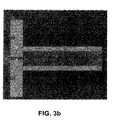
- Figure 3b shows a side view of Figure 3b and the effect on the power density of the longitudinal resonance of the slot.
- Figure 3c shows the density of a longitudinal resonance.
- Figure 3d shows the current density of a transverse resonance.
- Figure 3e shows simulated (gray line) and measured (black line) return losses with the frequency for both resonances.
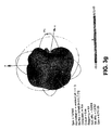
- Figure 3f shows the simulation of the far-field radiation pattern in three-dimensional format for the first resonance in the absence of corrugations
- Figure 3g shows the simulation of the far-field radiation pattern in three-dimensional format for the first resonance with the collimator effect of the corrugations.
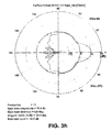
- Figure 3h shows the simulation of the E-plane far-field radiation pattern in polar coordinates for the first resonance in the presence of corrugations.
- figure 3i shows the simulation of the H-plane far-field radiation pattern in polar coordinates for the first resonance in the presence of corrugations.
- Figure 3j shows the simulation (continuous line) compared with the measurement (dotted line) of the E-plane far-field radiation pattern in Cartesian coordinates for the first resonance in the presence of corrugations.
- Figure 3k shows the simulation (continuous line) compared with the measurement (dotted line) of the H-plane far-field radiation pattern in Cartesian coordinates for the first resonance in the presence cf corrugations.
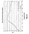
- Figure 31 shows the comparison of the gain with respect to the isotropic antenna for the antenna object of the patent (bottom line) and a standard horn (top line).
- Figure 3m shows a photograph of several antennas object of the present invention.
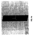
- Figure 4a shows an antenna with an increase in corrugations with respect to the antenna of Figure 2.
- Figure 4b shows an antenna such as the one of Figure 4a but with asymmetrical corrugations.
- Figure 4c shows the simulation of the far-field radiation pattern in three-dimensional format of the antenna of figure 4a, in which a greater collimator effect can be observed than in an antenna with one corrugation.
- Figure 4d shows the simulation of the far-field radiation pattern in three-dimensional format of the antenna of Figure 4b, in which collimation symmetry is observed with respect to the symmetrical antenna.
- Figure 5a shows a dual-band antenna.
- Figure 5b shows the surface current density on the radiating side for one of the operating frequencies of the dual-band antenna of Figure 5a.
- Figure 5c shows the surface current density on the radiating side for the other operating frequency, different from that of Figure 5b, in the dual-band antenna of Figure 5a.
Figure 5d shows a photograph of a dual-band antenna.
Figure 6a shows an antenna in which a material with a high index of refraction has been introduced in the corrugations.
Figure 6b shows a photograph of an ultraplanar antenna.
Figure 7a shows an antenna with annular corrugations.
Figure 7b shows the simulated (gray line) and measured (black line) return losses with the frequency.
Figure 7c shows the simulation for the far-field radiation pattern in three-dimensional format.
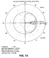
Figure 7d shows the simulation of the E-plan far-field radiation pattern in polar coordinates in which the strong collimating effect of t.he annular corrugations is observed.
Figure 7e shows the simulation of the H-plane far-field radiation pattern in polar coordinates.
Figure 7f shows the simulation (continuous line) compared with the measurement (dotted line) of the E-plane far-field radiation pattern in Cartesian coordinates.
Figure 7g shows the simulation (continuous line) compared with the measurement (dotted line) of the H-plane far-field radiation pattern in Cartesian coordinates.
Figure 7h shows the comparison of the gain with respect to the isotropic antenna for the antenna object of the patent (black line) and a standard horn (gray line)
Figure 7i shows an antenna with annular corrugations. - Figure 1 shows a diagram of an antenna object of the present application consisting of a slot surrounded by an indefinite number of corrugations on either of its sides and arranged on a metallic plate. The performance of said antenna with regard to collimation and transmission in the E-plane can be observed in Figure 1b. For the case of illuminating the structure with a planar wave, the comparison between the E-plane radiation pattern for the case of the absence of corrugations can be observed as a dotted line with inverted triangles, whereas for the case in which the corrugations are opposite to the wave source, it is represented as a dashed line with squares, and finally for the case in which the corrugations are on the opposite side, it appears as a dashed line with black dots. This is the case in which collimation of the emitted radiation occurs..
- Figures 2a and 2b detail a planar antenna with a corrugation on each side of the slot and which resonates longitudinally. Figure 2a shows the radiating transverse side, in which the length of the metallic plate L, its width a, which may coincide with the outer width of the feed waveguide, the width of the slot w, its height h, the distance of the corrugations to the axis of horizontal symmetry of the antenna d, and the height of said corrugations s, are detailed. Figure 2b shows a longitudinal section of the antenna with the thickness E of the metallic plate, the outer height of the feed waveguide b, the depth of the corrugations p and their thickness s.
- The most immediate way to design this antenna consists of a waveguide coupled by longitudinal resonance, i.e. by means of the thickness of the metallic plate separating the inside of the guide from free space, as is shown in Figure 3a. For the purpose of minimizing the structure, only one corrugation has been included on each side of the slot on the metallic plate in this embodiment. Since the slot has a half-wavelength depth and acts as a Babry-Perot resonator in its fundamental resonance, a power coupling exists as shown in Figure 3b. Said outer corrugations exert only a collimating effort on the diffracted power in the form of a surface wave on the back side..
- In an example of applying the antenna in mobile communication bands, the resulting wavelength is high, which makes a compact design unfeasible, the design being appropriate for frequencies in the millimetric wave range given that the thickness of the metal, of the antenna is about a few millimeters Therefore, for application in the microwave range it is necessary to reduce the thickness of the metal, keeping the radiation features intact, achieving a different resonance at the working frequency and thus not being obliged to maintain a minimum thickness of the metallic structure. To resolve this, the slot is made to resonate in the transverse direction rather than to resonate longitudinally, said transverse resonance being directly related to the width of the slot, as can be seen in Figures 3c and 3d.
- Figure 3e shows the response in frequencies and in said figure two resonances are observed, one corresponding to the transverse resonance associated to the width of the slot, and the other one, which occurs at a higher frequency, is the longitudinal resonance associated to the thickness of the slot. This allows the antenna to work in two frequency bands, being necessary to adjust the corrugations to the chosen band.
- To optimize far-field radiation it is necessary to vary the distance between the slot and the corrugations. Figures 3f and 3g, equivalent to the three-dimensional radiation patterns for an isolated slot and another slot with corrugations, respectively, allow comparing the radiations of both. An isotropic radiation pattern is obtained for the case of a slot without corrugations (3f) whereas a collimated radiation pattern is observed for the case in which the corrugations have been provided (3g). The details of said patterns in the E and H planes are also shown in Figures 3h and 3i, in polar coordinate format, for the case with the presence of corrugations
- The good correspondence between the simulation and the measurements performed in an anechoic chamber axe shown in Figures 3j and 3k for the E and H planes, respectively, in Cartesian coordinate format, i.e.. the antenna sweeping angle on the x-axis and the signal level related to the maximum in decibels on the y-axis.
- The gain of the antenna object of the invention has also been compared in frequency with a considerably larger horn antenna, as can be seen in Figure 31.
- Figure 3m finally shows different manufactured designs demonstrating the possibility of making intrinsically planar and compact models.
- A larger number of corrugations are used in the embodiment example shown in Figures 4a and 4b, obtaining considerable improvement in collimation, as can be seen in the three-dimensional far-field radiation pattern of Figure 4c. Figure 4d shows the three-dimensional far-field radiation pattern of the antenna of Figure 4b, thus demonstrating the possibility of obtaining asymmetrical collimation by means of the use of an asymmetrical corrugated structure, i.e. with corrugations only on one of the sides of the slot.
- After the foregoing description it is possible to make an antenna that is capable of operating at two independent frequency bands by taking advantage of the fact that two independent resonances, longitudinal resonance and transverse resonance, can be excited in the slot, it further being possible to obtain a focus at different frequencies by means of regulating corrugation distance and depth.
- figure 5a shows a planar antenna such as the one previously described in which additional corrugations have been introduced, specifically an additional corrugation one each side of the slot for the purpose of achieving focalization at another frequency such that the response in frequency is barely affected by the introduction of said additional corrugations. The current distributions for the two working frequencies are represented in Figures 5b and 5c.
- In this antenna with two corrugations on each side of the slot, said corrugations are only excited at the frequency that corresponds to them and are transparent for the other resonance. It is appropriate to point out that as in the case of the previous antenna with only one corrugation on each side of the slot, its corresponding three-dimensional far-field radiation patterns at both frequencies improve with respect to those that are obtained without corrugations.
- In the previous dual-band antenna it is possible to fix, completely independently from one another, its resonance frequencies by means of controlling the width and thickness of the central slot, the corrugations being sensitive only to their design frequency and transparent for the other resonance. Figure 5d shows a manufactured dual-band antenna design.
- To achieve proper working it is indispensable to respect a minimum quarter wavelength width in order to be able to excavate corrugations in the metal, this condition possibly making t.he antenna unfeasible for certain applications in which the ultraplanar nature of the antenna is fundamental.
- In order tc resolve the foregoing, the introduction of a dielectric element with low losses and suitable relative dielectric permittivity inside the cavity formed by the corrugations is proposed. The introduction of said dielectric element allows a considerable reduction of thickness, as can be observed in Figure 6a and in the photograph of Figure 6 b, in which a manufactured ultraplanar antenna prototype is shown.
- Due to the properties previously described it is possible to make a planar antenna which prevents feeding the antenna with a waveguide, allowing the application of planar antennas to planar and monolithic circuits by means of a completely planar design on a microwave substrate with corrugations excavated on the substrate and subsequent metallization, being possible to include via-holes facilitating connection between plates.
- It is also possible to cany out a planar antenna design by using concentric corrugations around the slot with transverse and longitudinal resonance, as can be seen in Figure 7a. Figure 7b shows the response in frequencies, two resonances being observed corresponding to the transverse and longitudinal modes. The collimating effect of this antenna is much more pronounced than the previous designs, as can be seen in Figures 7c to 7e, in which the simulations of the three. dimensional E-plane (7d) and H-piane (7e) fax-field radiation pattern are represented. The simulations have been confirmed by the measurements carried out, as can be seen in Figures 7f and 7g, for the far-field radiation pattern for the E and H planes, respectively, represented in Cartesian coordinates.
- The gain of the antenna object of the invention has also been compared in frequency with a horn antenna of evidently larger dimensions, as can be seen in Figure 7h.
- Figure 7i finally shows a manufactured design of this antenna.
- The planar structure of the previously described antennas can be used without a connection to a waveguide or to a circuit, simply as a selective surface receiving the waves in free space and allowing those which have a given frequency and given angle of incidence pass. Any of the previously described embodiments can be applied to this selective surface,
Claims (20)
- An antenna of a planar profile used for the emission and reception of electromagnetic waves, preferably in the millimetric wave and microwave ranges, characterized in that it comprises a planar surface of little thickness with at least one thin slot traversing the planar surface of little thickness, the length of said thin slot being less than the wavelength of the emitted and received wave, and said planar surface having at least one pair of corrugations around the thin slot such that the electromagnetic wave is emitted and received by means of resonance through said slot
- An antenna according to claim 1, characterized in that the resonance through the slot is longitudinal.
- An antenna according to claim 1, characterized in that the resonance through the slot is transverse.
- An antenna according to the previous claims, characterized in that it has a waveguide connected for the emission and reception of electromagnetic waves.
- An antenna according to the previous claims, characterized in that it has at least two pairs of corrugations and it combines transverse and longitudinal resonance so as to operate simultaneously in at least two different frequencies.
- An antenna according to claims 1 to 5, characterized in that it inside the corrugations it has a material with an index of refraction different from that of the air.
- An antenna according to the previous claims, characterized in that inside the waveguide it has a material with an index of refraction different from that of the air.
- An antenna according to the previous claims, characterized in that the corrugations are symmetrical with respect to the transverse axis of the antenna.
- An antenna according to the previous claims, characterized in that the corrugations are located only on one side of the transverse axis of the antenna.
- An antenna according to the previous claims, characterized in that the corrugations are straight.
- An antenna according to the previous claims, characterised in that the corrugations are curved and are arranged around the thin slot.
- An antenna according to the previous claims, characterized in that it is coupled to a planar technology circuit by means of the resonant slot.
- An antenna according to any of the previous claims, characterized in that it is coupled to a monolithic circuit carried out by means of monolithic integrated circuit manufacturing processes by means of the resonant slot.
- An antenna according to any of the previous claims, characterized in that it is made by means of micromachining manufacturing processes.
- An antenna according to any of the previous claims, characterized in that it is of a metallic material.
- An antenna according to the previous claims, characterized in that the corrugation profile is rectangular.
- An antenna according to the previous claims, characterized in that the corrugation profile is triangular.
- An antenna according to the previous claims, characterized in that the corrugation profile is sinusoidal.
- An antenna according to the previous claims, characterized in that it incorporates active elements, such as MEMS-type (Micro-Electromechanical Systems) electromechanical microswitches.
- A frequency selective surface characterized by comprising an extensive slot on a metallic plate which allows handling electromagnetic waves for the purpose of carrying out a frequency filtering.
Applications Claiming Priority (1)
| Application Number | Priority Date | Filing Date | Title |
|---|---|---|---|
| PCT/ES2004/000359 WO2006030034A1 (en) | 2004-08-03 | 2004-08-03 | Flat antenna |
Publications (2)
| Publication Number | Publication Date |
|---|---|
| EP1788664A1 true EP1788664A1 (en) | 2007-05-23 |
| EP1788664B1 EP1788664B1 (en) | 2008-10-29 |
Family
ID=36059716
Family Applications (1)
| Application Number | Title | Priority Date | Filing Date |
|---|---|---|---|
| EP04766898A Expired - Lifetime EP1788664B1 (en) | 2004-08-03 | 2004-08-03 | Flat antenna |
Country Status (6)
| Country | Link |
|---|---|
| US (1) | US20090167621A1 (en) |
| EP (1) | EP1788664B1 (en) |
| AT (1) | ATE412992T1 (en) |
| DE (1) | DE602004017523D1 (en) |
| ES (1) | ES2318326T3 (en) |
| WO (1) | WO2006030034A1 (en) |
Cited By (1)
| Publication number | Priority date | Publication date | Assignee | Title |
|---|---|---|---|---|
| CN111816979A (en) * | 2019-04-10 | 2020-10-23 | 华为技术有限公司 | Surface wave exciters and communication systems |
Families Citing this family (2)
| Publication number | Priority date | Publication date | Assignee | Title |
|---|---|---|---|---|
| US8521106B2 (en) * | 2009-06-09 | 2013-08-27 | Broadcom Corporation | Method and system for a sub-harmonic transmitter utilizing a leaky wave antenna |
| CN109616762B (en) * | 2019-01-07 | 2021-01-15 | 中国人民解放军国防科技大学 | A Ka-band high-gain substrate integrated waveguide corrugated antenna and system |
Family Cites Families (11)
| Publication number | Priority date | Publication date | Assignee | Title |
|---|---|---|---|---|
| GB600433A (en) * | 1945-10-31 | 1948-04-08 | Henry George Booker | Improvements in or relating to wireless aerials |
| US3212096A (en) * | 1961-09-25 | 1965-10-12 | Danver M Schuster | Parabolic reflector horn feed with spillover correction |
| US3274603A (en) * | 1963-04-03 | 1966-09-20 | Control Data Corp | Wide angle horn feed closely spaced to main reflector |
| US4554552A (en) * | 1981-12-21 | 1985-11-19 | Gamma-F Corporation | Antenna feed system with closely coupled amplifier |
| US4622559A (en) * | 1984-04-12 | 1986-11-11 | Canadian Patents & Development Limited | Paraboloid reflector antenna feed having a flange with tapered corrugations |
| IL121978A (en) * | 1997-10-14 | 2004-05-12 | Mti Wireless Edge Ltd | Flat plate antenna arrays |
| US6219001B1 (en) * | 1998-12-18 | 2001-04-17 | Ricoh Company, Ltd. | Tapered slot antenna having a corrugated structure |
| US6307519B1 (en) * | 1999-12-23 | 2001-10-23 | Hughes Electronics Corporation | Multiband antenna system using RF micro-electro-mechanical switches, method for transmitting multiband signals, and signal produced therefrom |
| DE10138265A1 (en) * | 2001-08-03 | 2003-07-03 | Siemens Ag | Antenna for radio-operated communication terminals |
| US6580561B2 (en) * | 2001-08-23 | 2003-06-17 | Raytheon Company | Quasi-optical variable beamsplitter |
| US6639566B2 (en) * | 2001-09-20 | 2003-10-28 | Andrew Corporation | Dual-polarized shaped-reflector antenna |
-
2004
- 2004-08-03 WO PCT/ES2004/000359 patent/WO2006030034A1/en not_active Ceased
- 2004-08-03 US US11/659,341 patent/US20090167621A1/en not_active Abandoned
- 2004-08-03 DE DE602004017523T patent/DE602004017523D1/en not_active Expired - Lifetime
- 2004-08-03 ES ES04766898T patent/ES2318326T3/en not_active Expired - Lifetime
- 2004-08-03 EP EP04766898A patent/EP1788664B1/en not_active Expired - Lifetime
- 2004-08-03 AT AT04766898T patent/ATE412992T1/en not_active IP Right Cessation
Non-Patent Citations (1)
| Title |
|---|
| See references of WO2006030034A1 * |
Cited By (1)
| Publication number | Priority date | Publication date | Assignee | Title |
|---|---|---|---|---|
| CN111816979A (en) * | 2019-04-10 | 2020-10-23 | 华为技术有限公司 | Surface wave exciters and communication systems |
Also Published As
| Publication number | Publication date |
|---|---|
| US20090167621A1 (en) | 2009-07-02 |
| DE602004017523D1 (en) | 2008-12-11 |
| WO2006030034A1 (en) | 2006-03-23 |
| ATE412992T1 (en) | 2008-11-15 |
| EP1788664B1 (en) | 2008-10-29 |
| ES2318326T3 (en) | 2009-05-01 |
Similar Documents
| Publication | Publication Date | Title |
|---|---|---|
| CA2176656C (en) | Broadband circularly polarized dielectric resonator antenna | |
| EP3972050B1 (en) | Antenna assembly and electronic device | |
| CN110911830B (en) | Passive Frequency Scanning Fabry-Perot Resonator Antenna | |
| JP2004015408A (en) | Slot array antenna | |
| JP2001320228A (en) | Dielectric leaky wave antenna | |
| EP2077603A2 (en) | Dielectric leaky wave antenna | |
| CN110867655B (en) | High front-to-back ratio directional antenna | |
| JP6569435B2 (en) | Array antenna | |
| KR20180052071A (en) | Antenna device including parabolic-hyperbolic reflector | |
| US20090167621A1 (en) | Flat antenna | |
| EP4111535B1 (en) | Communication device comprising a retroreflective structure | |
| CN120262031A (en) | Dielectric lens and dielectric lens antenna | |
| JP4027775B2 (en) | Slot array antenna | |
| US6700549B2 (en) | Dielectric-filled antenna feed | |
| US12034210B2 (en) | Leaky wave antenna | |
| JPH0722833A (en) | Crossed slot microwave antenna | |
| JP2003158421A (en) | Dielectric leaky wave antenna | |
| CN119315263B (en) | Antennas, reflector antenna systems and electronic equipment | |
| CN220233463U (en) | Phased array antenna and communication device | |
| CN116632519B (en) | Medium antenna and communication device | |
| JPH09121116A (en) | Planar antenna | |
| Ulfah | A high-gain wideband antenna employing novel partial reflective surfaces | |
| Yeşilyurt | Design and realization of a broad band antenna loaded with a metamaterial-inspired lens for subsurface microwave imaging applications | |
| RU1830572C (en) | Antenna with slot exciter | |
| CN118801097A (en) | Inverted F antenna, inverted F antenna manufacturing method and terminal device |
Legal Events
| Date | Code | Title | Description |
|---|---|---|---|
| PUAI | Public reference made under article 153(3) epc to a published international application that has entered the european phase |
Free format text: ORIGINAL CODE: 0009012 |
|
| 17P | Request for examination filed |
Effective date: 20070305 |
|
| AK | Designated contracting states |
Kind code of ref document: A1 Designated state(s): AT BE BG CH CY CZ DE DK EE ES FI FR GB GR HU IE IT LI LU MC NL PL PT RO SE SI SK TR |
|
| 17Q | First examination report despatched |
Effective date: 20070928 |
|
| DAX | Request for extension of the european patent (deleted) | ||
| GRAP | Despatch of communication of intention to grant a patent |
Free format text: ORIGINAL CODE: EPIDOSNIGR1 |
|
| RIC1 | Information provided on ipc code assigned before grant |
Ipc: H01Q 13/10 20060101AFI20080424BHEP Ipc: H01Q 5/00 20060101ALI20080424BHEP |
|
| GRAS | Grant fee paid |
Free format text: ORIGINAL CODE: EPIDOSNIGR3 |
|
| GRAA | (expected) grant |
Free format text: ORIGINAL CODE: 0009210 |
|
| AK | Designated contracting states |
Kind code of ref document: B1 Designated state(s): AT BE BG CH CY CZ DE DK EE ES FI FR GB GR HU IE IT LI LU MC NL PL PT RO SE SI SK TR |
|
| REG | Reference to a national code |
Ref country code: GB Ref legal event code: FG4D |
|
| REG | Reference to a national code |
Ref country code: CH Ref legal event code: EP |
|
| REG | Reference to a national code |
Ref country code: IE Ref legal event code: FG4D |
|
| REF | Corresponds to: |
Ref document number: 602004017523 Country of ref document: DE Date of ref document: 20081211 Kind code of ref document: P |
|
| NLV1 | Nl: lapsed or annulled due to failure to fulfill the requirements of art. 29p and 29m of the patents act | ||
| PG25 | Lapsed in a contracting state [announced via postgrant information from national office to epo] |
Ref country code: AT Free format text: LAPSE BECAUSE OF FAILURE TO SUBMIT A TRANSLATION OF THE DESCRIPTION OR TO PAY THE FEE WITHIN THE PRESCRIBED TIME-LIMIT Effective date: 20081029 Ref country code: BG Free format text: LAPSE BECAUSE OF FAILURE TO SUBMIT A TRANSLATION OF THE DESCRIPTION OR TO PAY THE FEE WITHIN THE PRESCRIBED TIME-LIMIT Effective date: 20090129 |
|
| REG | Reference to a national code |
Ref country code: ES Ref legal event code: FG2A Ref document number: 2318326 Country of ref document: ES Kind code of ref document: T3 |
|
| PG25 | Lapsed in a contracting state [announced via postgrant information from national office to epo] |
Ref country code: PT Free format text: LAPSE BECAUSE OF FAILURE TO SUBMIT A TRANSLATION OF THE DESCRIPTION OR TO PAY THE FEE WITHIN THE PRESCRIBED TIME-LIMIT Effective date: 20090330 Ref country code: PL Free format text: LAPSE BECAUSE OF FAILURE TO SUBMIT A TRANSLATION OF THE DESCRIPTION OR TO PAY THE FEE WITHIN THE PRESCRIBED TIME-LIMIT Effective date: 20081029 Ref country code: SI Free format text: LAPSE BECAUSE OF FAILURE TO SUBMIT A TRANSLATION OF THE DESCRIPTION OR TO PAY THE FEE WITHIN THE PRESCRIBED TIME-LIMIT Effective date: 20081029 Ref country code: FI Free format text: LAPSE BECAUSE OF FAILURE TO SUBMIT A TRANSLATION OF THE DESCRIPTION OR TO PAY THE FEE WITHIN THE PRESCRIBED TIME-LIMIT Effective date: 20081029 Ref country code: NL Free format text: LAPSE BECAUSE OF FAILURE TO SUBMIT A TRANSLATION OF THE DESCRIPTION OR TO PAY THE FEE WITHIN THE PRESCRIBED TIME-LIMIT Effective date: 20081029 |
|
| PG25 | Lapsed in a contracting state [announced via postgrant information from national office to epo] |
Ref country code: EE Free format text: LAPSE BECAUSE OF FAILURE TO SUBMIT A TRANSLATION OF THE DESCRIPTION OR TO PAY THE FEE WITHIN THE PRESCRIBED TIME-LIMIT Effective date: 20081029 Ref country code: BE Free format text: LAPSE BECAUSE OF FAILURE TO SUBMIT A TRANSLATION OF THE DESCRIPTION OR TO PAY THE FEE WITHIN THE PRESCRIBED TIME-LIMIT Effective date: 20081029 Ref country code: DK Free format text: LAPSE BECAUSE OF FAILURE TO SUBMIT A TRANSLATION OF THE DESCRIPTION OR TO PAY THE FEE WITHIN THE PRESCRIBED TIME-LIMIT Effective date: 20081029 Ref country code: RO Free format text: LAPSE BECAUSE OF FAILURE TO SUBMIT A TRANSLATION OF THE DESCRIPTION OR TO PAY THE FEE WITHIN THE PRESCRIBED TIME-LIMIT Effective date: 20081029 |
|
| PG25 | Lapsed in a contracting state [announced via postgrant information from national office to epo] |
Ref country code: CZ Free format text: LAPSE BECAUSE OF FAILURE TO SUBMIT A TRANSLATION OF THE DESCRIPTION OR TO PAY THE FEE WITHIN THE PRESCRIBED TIME-LIMIT Effective date: 20081029 Ref country code: SE Free format text: LAPSE BECAUSE OF FAILURE TO SUBMIT A TRANSLATION OF THE DESCRIPTION OR TO PAY THE FEE WITHIN THE PRESCRIBED TIME-LIMIT Effective date: 20090129 |
|
| PLBE | No opposition filed within time limit |
Free format text: ORIGINAL CODE: 0009261 |
|
| PG25 | Lapsed in a contracting state [announced via postgrant information from national office to epo] |
Ref country code: SK Free format text: LAPSE BECAUSE OF FAILURE TO SUBMIT A TRANSLATION OF THE DESCRIPTION OR TO PAY THE FEE WITHIN THE PRESCRIBED TIME-LIMIT Effective date: 20081029 |
|
| 26N | No opposition filed |
Effective date: 20090730 |
|
| PG25 | Lapsed in a contracting state [announced via postgrant information from national office to epo] |
Ref country code: MC Free format text: LAPSE BECAUSE OF NON-PAYMENT OF DUE FEES Effective date: 20090831 |
|
| REG | Reference to a national code |
Ref country code: CH Ref legal event code: PL |
|
| PG25 | Lapsed in a contracting state [announced via postgrant information from national office to epo] |
Ref country code: LI Free format text: LAPSE BECAUSE OF NON-PAYMENT OF DUE FEES Effective date: 20090831 Ref country code: CH Free format text: LAPSE BECAUSE OF NON-PAYMENT OF DUE FEES Effective date: 20090831 |
|
| PG25 | Lapsed in a contracting state [announced via postgrant information from national office to epo] |
Ref country code: IE Free format text: LAPSE BECAUSE OF NON-PAYMENT OF DUE FEES Effective date: 20090803 |
|
| PG25 | Lapsed in a contracting state [announced via postgrant information from national office to epo] |
Ref country code: GR Free format text: LAPSE BECAUSE OF FAILURE TO SUBMIT A TRANSLATION OF THE DESCRIPTION OR TO PAY THE FEE WITHIN THE PRESCRIBED TIME-LIMIT Effective date: 20090130 |
|
| PG25 | Lapsed in a contracting state [announced via postgrant information from national office to epo] |
Ref country code: LU Free format text: LAPSE BECAUSE OF NON-PAYMENT OF DUE FEES Effective date: 20090803 |
|
| PG25 | Lapsed in a contracting state [announced via postgrant information from national office to epo] |
Ref country code: HU Free format text: LAPSE BECAUSE OF FAILURE TO SUBMIT A TRANSLATION OF THE DESCRIPTION OR TO PAY THE FEE WITHIN THE PRESCRIBED TIME-LIMIT Effective date: 20090430 |
|
| PG25 | Lapsed in a contracting state [announced via postgrant information from national office to epo] |
Ref country code: TR Free format text: LAPSE BECAUSE OF FAILURE TO SUBMIT A TRANSLATION OF THE DESCRIPTION OR TO PAY THE FEE WITHIN THE PRESCRIBED TIME-LIMIT Effective date: 20081029 |
|
| PG25 | Lapsed in a contracting state [announced via postgrant information from national office to epo] |
Ref country code: CY Free format text: LAPSE BECAUSE OF FAILURE TO SUBMIT A TRANSLATION OF THE DESCRIPTION OR TO PAY THE FEE WITHIN THE PRESCRIBED TIME-LIMIT Effective date: 20081029 |
|
| PGFP | Annual fee paid to national office [announced via postgrant information from national office to epo] |
Ref country code: DE Payment date: 20140827 Year of fee payment: 11 |
|
| PGFP | Annual fee paid to national office [announced via postgrant information from national office to epo] |
Ref country code: ES Payment date: 20140703 Year of fee payment: 11 Ref country code: GB Payment date: 20140827 Year of fee payment: 11 Ref country code: FR Payment date: 20140818 Year of fee payment: 11 |
|
| PGFP | Annual fee paid to national office [announced via postgrant information from national office to epo] |
Ref country code: IT Payment date: 20140825 Year of fee payment: 11 |
|
| REG | Reference to a national code |
Ref country code: DE Ref legal event code: R119 Ref document number: 602004017523 Country of ref document: DE |
|
| GBPC | Gb: european patent ceased through non-payment of renewal fee |
Effective date: 20150803 |
|
| PG25 | Lapsed in a contracting state [announced via postgrant information from national office to epo] |
Ref country code: IT Free format text: LAPSE BECAUSE OF NON-PAYMENT OF DUE FEES Effective date: 20150803 |
|
| REG | Reference to a national code |
Ref country code: FR Ref legal event code: ST Effective date: 20160429 |
|
| PG25 | Lapsed in a contracting state [announced via postgrant information from national office to epo] |
Ref country code: DE Free format text: LAPSE BECAUSE OF NON-PAYMENT OF DUE FEES Effective date: 20160301 Ref country code: GB Free format text: LAPSE BECAUSE OF NON-PAYMENT OF DUE FEES Effective date: 20150803 |
|
| PG25 | Lapsed in a contracting state [announced via postgrant information from national office to epo] |
Ref country code: FR Free format text: LAPSE BECAUSE OF NON-PAYMENT OF DUE FEES Effective date: 20150831 |
|
| REG | Reference to a national code |
Ref country code: ES Ref legal event code: FD2A Effective date: 20160927 |
|
| PG25 | Lapsed in a contracting state [announced via postgrant information from national office to epo] |
Ref country code: ES Free format text: LAPSE BECAUSE OF NON-PAYMENT OF DUE FEES Effective date: 20150804 |