EP1788656A1 - Solid oxide fuel cell stack with a gas flow regulating member between casing and stack - Google Patents
Solid oxide fuel cell stack with a gas flow regulating member between casing and stack Download PDFInfo
- Publication number
- EP1788656A1 EP1788656A1 EP06024210A EP06024210A EP1788656A1 EP 1788656 A1 EP1788656 A1 EP 1788656A1 EP 06024210 A EP06024210 A EP 06024210A EP 06024210 A EP06024210 A EP 06024210A EP 1788656 A1 EP1788656 A1 EP 1788656A1
- Authority
- EP
- European Patent Office
- Prior art keywords
- fuel cell
- gas
- casing
- regulating member
- stack structure
- Prior art date
- Legal status (The legal status is an assumption and is not a legal conclusion. Google has not performed a legal analysis and makes no representation as to the accuracy of the status listed.)
- Granted
Links
- 239000000446 fuel Substances 0.000 title claims abstract description 257
- 239000007787 solid Substances 0.000 title claims abstract description 10
- 230000001105 regulatory effect Effects 0.000 title description 3
- 239000007789 gas Substances 0.000 claims abstract description 283
- 230000002093 peripheral effect Effects 0.000 claims abstract description 51
- 239000002737 fuel gas Substances 0.000 claims abstract description 25
- 239000000463 material Substances 0.000 claims description 103
- 239000000945 filler Substances 0.000 claims description 60
- 238000005192 partition Methods 0.000 claims description 25
- 125000006850 spacer group Chemical group 0.000 claims description 7
- 238000010276 construction Methods 0.000 description 29
- 239000002184 metal Substances 0.000 description 19
- 239000000919 ceramic Substances 0.000 description 16
- 239000010410 layer Substances 0.000 description 15
- 230000004048 modification Effects 0.000 description 12
- 238000012986 modification Methods 0.000 description 12
- 239000000853 adhesive Substances 0.000 description 10
- 230000001070 adhesive effect Effects 0.000 description 10
- 239000004568 cement Substances 0.000 description 9
- 238000010248 power generation Methods 0.000 description 9
- 230000035939 shock Effects 0.000 description 9
- 239000000835 fiber Substances 0.000 description 8
- 238000005187 foaming Methods 0.000 description 8
- 230000006872 improvement Effects 0.000 description 8
- 230000005855 radiation Effects 0.000 description 8
- 239000011148 porous material Substances 0.000 description 6
- 230000009467 reduction Effects 0.000 description 6
- 239000007784 solid electrolyte Substances 0.000 description 6
- 239000013585 weight reducing agent Substances 0.000 description 6
- 239000011248 coating agent Substances 0.000 description 5
- 238000000576 coating method Methods 0.000 description 5
- 239000011888 foil Substances 0.000 description 5
- 239000011521 glass Substances 0.000 description 5
- 238000003466 welding Methods 0.000 description 5
- 239000002131 composite material Substances 0.000 description 4
- 239000004744 fabric Substances 0.000 description 4
- 239000003365 glass fiber Substances 0.000 description 4
- 238000002156 mixing Methods 0.000 description 4
- 238000000465 moulding Methods 0.000 description 4
- 238000007711 solidification Methods 0.000 description 4
- 230000008023 solidification Effects 0.000 description 4
- 230000035882 stress Effects 0.000 description 4
- 238000005219 brazing Methods 0.000 description 3
- 230000008859 change Effects 0.000 description 3
- 239000003792 electrolyte Substances 0.000 description 3
- 239000006082 mold release agent Substances 0.000 description 3
- 239000000843 powder Substances 0.000 description 3
- 230000001737 promoting effect Effects 0.000 description 3
- 230000001052 transient effect Effects 0.000 description 3
- 229910052582 BN Inorganic materials 0.000 description 2
- PZNSFCLAULLKQX-UHFFFAOYSA-N Boron nitride Chemical compound N#B PZNSFCLAULLKQX-UHFFFAOYSA-N 0.000 description 2
- PNEYBMLMFCGWSK-UHFFFAOYSA-N aluminium oxide Inorganic materials [O-2].[O-2].[O-2].[Al+3].[Al+3] PNEYBMLMFCGWSK-UHFFFAOYSA-N 0.000 description 2
- 230000002542 deteriorative effect Effects 0.000 description 2
- 238000007599 discharging Methods 0.000 description 2
- 238000005516 engineering process Methods 0.000 description 2
- 238000005530 etching Methods 0.000 description 2
- 238000010438 heat treatment Methods 0.000 description 2
- 230000007257 malfunction Effects 0.000 description 2
- 238000007639 printing Methods 0.000 description 2
- 239000002344 surface layer Substances 0.000 description 2
- 230000008646 thermal stress Effects 0.000 description 2
- OKTJSMMVPCPJKN-UHFFFAOYSA-N Carbon Chemical compound [C] OKTJSMMVPCPJKN-UHFFFAOYSA-N 0.000 description 1
- 229910019142 PO4 Inorganic materials 0.000 description 1
- 239000011398 Portland cement Substances 0.000 description 1
- 229910000831 Steel Inorganic materials 0.000 description 1
- 239000012790 adhesive layer Substances 0.000 description 1
- 238000005452 bending Methods 0.000 description 1
- 239000011230 binding agent Substances 0.000 description 1
- 229910052799 carbon Inorganic materials 0.000 description 1
- 239000011247 coating layer Substances 0.000 description 1
- 238000002485 combustion reaction Methods 0.000 description 1
- 239000004020 conductor Substances 0.000 description 1
- 230000003247 decreasing effect Effects 0.000 description 1
- 210000003298 dental enamel Anatomy 0.000 description 1
- 238000001035 drying Methods 0.000 description 1
- 239000007772 electrode material Substances 0.000 description 1
- 230000002708 enhancing effect Effects 0.000 description 1
- 238000010304 firing Methods 0.000 description 1
- 239000002241 glass-ceramic Substances 0.000 description 1
- 238000000227 grinding Methods 0.000 description 1
- 239000010440 gypsum Substances 0.000 description 1
- 229910052602 gypsum Inorganic materials 0.000 description 1
- 230000020169 heat generation Effects 0.000 description 1
- 229910001026 inconel Inorganic materials 0.000 description 1
- 230000001678 irradiating effect Effects 0.000 description 1
- 230000001788 irregular Effects 0.000 description 1
- 239000010445 mica Substances 0.000 description 1
- 229910052618 mica group Inorganic materials 0.000 description 1
- 239000004570 mortar (masonry) Substances 0.000 description 1
- 239000011368 organic material Substances 0.000 description 1
- 238000000059 patterning Methods 0.000 description 1
- 239000010452 phosphate Substances 0.000 description 1
- NBIIXXVUZAFLBC-UHFFFAOYSA-K phosphate Chemical compound [O-]P([O-])([O-])=O NBIIXXVUZAFLBC-UHFFFAOYSA-K 0.000 description 1
- 238000003825 pressing Methods 0.000 description 1
- 230000004044 response Effects 0.000 description 1
- 230000004043 responsiveness Effects 0.000 description 1
- 239000003469 silicate cement Substances 0.000 description 1
- 229910001220 stainless steel Inorganic materials 0.000 description 1
- 239000010935 stainless steel Substances 0.000 description 1
- 239000010959 steel Substances 0.000 description 1
- 238000004381 surface treatment Methods 0.000 description 1
Images













Classifications
-
- H—ELECTRICITY
- H01—ELECTRIC ELEMENTS
- H01M—PROCESSES OR MEANS, e.g. BATTERIES, FOR THE DIRECT CONVERSION OF CHEMICAL ENERGY INTO ELECTRICAL ENERGY
- H01M8/00—Fuel cells; Manufacture thereof
- H01M8/04—Auxiliary arrangements, e.g. for control of pressure or for circulation of fluids
- H01M8/04082—Arrangements for control of reactant parameters, e.g. pressure or concentration
- H01M8/04089—Arrangements for control of reactant parameters, e.g. pressure or concentration of gaseous reactants
-
- H—ELECTRICITY
- H01—ELECTRIC ELEMENTS
- H01M—PROCESSES OR MEANS, e.g. BATTERIES, FOR THE DIRECT CONVERSION OF CHEMICAL ENERGY INTO ELECTRICAL ENERGY
- H01M8/00—Fuel cells; Manufacture thereof
- H01M8/24—Grouping of fuel cells, e.g. stacking of fuel cells
- H01M8/241—Grouping of fuel cells, e.g. stacking of fuel cells with solid or matrix-supported electrolytes
- H01M8/2425—High-temperature cells with solid electrolytes
- H01M8/243—Grouping of unit cells of tubular or cylindrical configuration
-
- H—ELECTRICITY
- H01—ELECTRIC ELEMENTS
- H01M—PROCESSES OR MEANS, e.g. BATTERIES, FOR THE DIRECT CONVERSION OF CHEMICAL ENERGY INTO ELECTRICAL ENERGY
- H01M8/00—Fuel cells; Manufacture thereof
- H01M8/24—Grouping of fuel cells, e.g. stacking of fuel cells
- H01M8/2465—Details of groupings of fuel cells
- H01M8/2484—Details of groupings of fuel cells characterised by external manifolds
-
- H—ELECTRICITY
- H01—ELECTRIC ELEMENTS
- H01M—PROCESSES OR MEANS, e.g. BATTERIES, FOR THE DIRECT CONVERSION OF CHEMICAL ENERGY INTO ELECTRICAL ENERGY
- H01M8/00—Fuel cells; Manufacture thereof
- H01M8/10—Fuel cells with solid electrolytes
- H01M8/12—Fuel cells with solid electrolytes operating at high temperature, e.g. with stabilised ZrO2 electrolyte
- H01M2008/1293—Fuel cells with solid oxide electrolytes
-
- H—ELECTRICITY
- H01—ELECTRIC ELEMENTS
- H01M—PROCESSES OR MEANS, e.g. BATTERIES, FOR THE DIRECT CONVERSION OF CHEMICAL ENERGY INTO ELECTRICAL ENERGY
- H01M8/00—Fuel cells; Manufacture thereof
- H01M8/24—Grouping of fuel cells, e.g. stacking of fuel cells
- H01M8/2465—Details of groupings of fuel cells
- H01M8/247—Arrangements for tightening a stack, for accommodation of a stack in a tank or for assembling different tanks
-
- Y—GENERAL TAGGING OF NEW TECHNOLOGICAL DEVELOPMENTS; GENERAL TAGGING OF CROSS-SECTIONAL TECHNOLOGIES SPANNING OVER SEVERAL SECTIONS OF THE IPC; TECHNICAL SUBJECTS COVERED BY FORMER USPC CROSS-REFERENCE ART COLLECTIONS [XRACs] AND DIGESTS
- Y02—TECHNOLOGIES OR APPLICATIONS FOR MITIGATION OR ADAPTATION AGAINST CLIMATE CHANGE
- Y02E—REDUCTION OF GREENHOUSE GAS [GHG] EMISSIONS, RELATED TO ENERGY GENERATION, TRANSMISSION OR DISTRIBUTION
- Y02E60/00—Enabling technologies; Technologies with a potential or indirect contribution to GHG emissions mitigation
- Y02E60/30—Hydrogen technology
- Y02E60/50—Fuel cells
Definitions
- the present invention relates to a fuel cell composed by housing, in a casing, a stack structure formed by stacking a plurality of solid oxide fuel cell units on one another.
- the fuel cell described above includes a stack structure composed by fastening the respective center portions of the plurality of fuel cell units stacked on one another. Accordingly, the respective outer peripheral edges of the fuel cell units are not fixed, and are placed in a free state. Therefore, the fuel cell has a less breakable construction against thermal shock caused by quick heating and the like.
- mechanical vibrations are applied entirely to the fuel cell as in the case where the fuel cell is mounted on a vehicle, there has been an apprehension that the respective outer peripheral edges of the fuel cell units vibrate resonantly to apply a mechanical stress to the cells, causing a malfunction such as a crack.
- the present invention has been made in consideration for the problems as described above inherent in the related art. It is an object of the present invention to provide a fuel cell which is, even if there is a gap between the casing and the stack structure, capable of obtaining sufficient generated power, and in addition, capable of enhancing durability thereof against the mechanical vibrations.
- a fuel cell including: a stack structure composed by stacking a plurality of solid oxide fuel cell units with current collectors, each of the fuel cell unit including: a cell plate which holds at least one cell and has a gas introduction hole for one of fuel gas and air in a center portion thereof; and a separator plate which has a gas introduction hole for the one of the fuel gas and the air in a center portion thereof and makes an outer peripheral edge thereof entirely bonded to an outer peripheral edge of the cell plate; a casing housing the stack structure, the casing including a gas introduction portion and a gas discharge portion, and the casing introducing the other of the fuel gas and the air thereinto from the gas introduction portion and flowing the other gas to the gas discharge portion; and a gas flow-regulating member provided in a gap between the casing and the stack structure in order to flow the other gas to the gas discharge portion through the current collectors located between the fuel cell units
- a fuel cell according to the present invention includes solid oxide fuel cell units.
- Each of the solid oxide fuel cell units includes a cell plate which holds a cell and has a gas introduction hole for one of fuel gas and air in a center portion thereof, and a separator plate which has a gas introduction hole for the one of the fuel gas and the air in a center portion thereof and makes an outer peripheral edge thereof bonded to an outer peripheral edge of the cell plate.
- a plurality of the above-described fuel cell units are stacked on one another with current collectors, thereby forming a stack structure.
- the above-described fuel cell includes a casing.
- the casing includes a gas introduction portion and a gas discharge portion, and introduces the other of the fuel gas and the air thereinto from the gas introduction portion and flows the other gas to the gas discharge portion in a state of housing the stack structure therein.
- the one of the fuel gas and the air is supplied from the respective gas introduction holes of the cell plate and the separator plate into the fuel cell units.
- the one gas supplied into the fuel cell units may be discharged from centers of the units by forming gas discharge holes in the center portions of the fuel cell units, or may be discharged from outer peripheries of the units by forming notches for discharging the gas on outer peripheral edges of the fuel cell units.
- the present invention is characterized in that a gas flow-regulating member is provided in a gap between the casing and the stack structure in order to flow the other gas to the gas discharge portion through the current collectors located between the fuel cell units of the stack structure, the other gas being introduced into the casing from the gas introduction portion.
- a gas flow-regulating member With providing the gas flow-regulating member, it becomes easier for the other gas introduced from the gas introduction portion of the casing to flow through a portion of the current collectors between the fuel cell units stacked on one another in the stack structure than through the gap between the casing and the stack structure. Therefore, a supply amount of the other gas to the cells held by the cell plates will be increased to a great extent, resulting in that sufficient generated power can be obtained.
- the discharge of the one gas from the gas discharge portion of the casing can be restricted by the gas flow-regulating member. Therefore, it becomes possible to prevent a backfire to the fuel cell units at a time when the fuel cell is under transient operation. As a result, it is possible to perform a stable operation, and it becomes possible to avoid a thermal shock.
- a thickness of the center portion of each fuel cell unit is made larger than a thickness of a region thereof where the cell is installed, thereby giving a function of a spacer to the center portion.
- Each fuel cell unit in the fuel cell according to the present invention is composed by bonding the respective outer peripheral edges of the cell plate and the separator plate to each other. Specifically, a step along the outer peripheral edge is provided in at least one of the cell plate and the separator plate, and thereafter, the outer peripheral edges are bonded to each other. Thus, between the cell plate and the separator plate, there is formed a space through which the one of the fuel gas and the air flows.
- the steps provided on the cell plate and separator plate of the fuel cell unit be formed by press work. Furthermore, for bonding the respective outer peripheral edges of the cell plate and the separator plate to each other, not only welding and brazing can be used, but also ultrasonic bonding and the like can be used.
- attachment positions of the cells of the fuel cell unit can be set in a region which forms a doughnut shape between the center portion and outer peripheral edge of the cell plate.
- One or more cells can be fixed into the region which forms the doughnut shape.
- the cells when the cell forms a small-diameter disc shape, it is desirable that the cells be arranged regularly around the center of the cell plate.
- an inner ring and an outer ring which have been subjected to the press work, be bonded to inner and outer peripheral edges of the cell, respectively.
- the inner ring and the outer ring may be coupled to each other to form a frame shape, and it is also possible to attach cells of a sector shape to the frame.
- the stack structure is composed by stacking the plurality of fuel cell units, and gas seal bonding layers are interposed between the respective center portions of the fuel cell units stacked on one another.
- gas seal bonding layers not only an inorganic bonding material such as a ceramic-based adhesive and a glass-based adhesive which have electrically insulating property can be used, but also a conductive bonding material mixed with a brazing material and metal powder, and gasket seal layers can be used, for example, when the cells form the doughnut shape.
- inter-unit current collectors are interposed between the respective cell regions of the fuel cell units.
- conductive porous bodies can be used.
- metal mesh and foaming metal can be used, but also fabric and felt of fiber made of metal or an electrode material can be used.
- the stack structure is formed in such a manner that a flange, which includes an introduction pipe supplying the one gas into the fuel cell units, and a flange, which includes an exhaust pipe discharging the one gas from the fuel cell units, are installed on and under the stacked fuel cell units.
- a plan shape of the fuel cell unit which forms the stack structure and an opening shape of the casing which houses the stack structure therein are not limited to the circular shape, and for example, may be a quadrangular shape, a polygonal shape, and a cloudy shape.
- the gas introduction portion and gas discharge portion of the casing can be arranged toward a side surface of the stack structure, and can be arranged toward upper and lower surfaces of the stack structure.
- the number of stack structure housed in the casing is not limited to one, and a construction in which a plurality thereof are housed may be adopted.
- the number of each of the gas introduction portion and gas discharge portion of the casing is not limited to one, and a plurality of each thereof can also be installed.
- an indefinite material which includes a castable refractory, fireproof foaming cement such as portland cement, alumina cement, phosphate cement, and silicate cement, fireproof mortar, gypsum, a ceramic adhesive, and bubble glass; and a sheet material or a molded body which includes felt, fabric, and knit which are mainly composed of glass fiber, ceramic fiber, and metal fiber, a composite material thereof, and metal foil.
- the gas flow-regulating member is not limited to any of the above.
- the above-described gas flow-regulating member can be formed of a composite material obtained by mixing thereinto filler which is particulate, fibrous, chip-like, and so on, the filler being made of metal or ceramics, which is good in thermal conductivity.
- the gas flow-regulating member can also be composed of a porous body by mixing and molding thereinto an organic material and carbon filler, followed by firing.
- an installed position of the gas flow-regulating member depends on stack specifications such as the number of gas introduction portion and gas discharge portion of the casing, a ratio of an outer diameter of the fuel cell units and a diameter of the center portions thereof, an interval between the fuel cell units, opening widths of the gas introduction portion and gas discharge portion of the casing, a ratio in porosity of the inter-unit current collectors and the gas flow-regulating member, and an output density of the cells.
- the above-described installed position also depends on operation conditions such as a gas flow rate and an operation temperature.
- the gas flow-regulating member is provided only in the vicinity of the gas introduction portion of the casing and the vicinity of the gas discharge portion thereof.
- an angel R made by a line X-O which connects a center X of the gas introduction portion 12a (gas discharge portion) of the casing 12 and a center O of the fuel cell units 1 to each other and by a line O-Y which connects the center O of the fuel cell units 1 and a terminal end of the disposed gas flow-regulating member 16 be 15° or more.
- the gas flow-regulating member 16 may be disposed over the entire periphery of the gap excluding the gas introduction portion 12a and the gas discharge portion 12b.
- a construction in which the gas flow-regulating member and the respective fuel cell units of the stack structure are mutually movably brought into contact with each other.
- the gas flow-regulating member and the fuel cell units are completely adhered onto each other, distortion sometimes occurs in bonded portions thereof owing to a difference in thermal expansion coefficient between the materials constructing the respective members.
- the fuel cell units will improve the thermal shock resistance thereof and make themselves thinner. Further, a stack structure with a low heat capacity, which is excellent in starting easiness and responsiveness, can be obtained.
- the gas flow-regulating member can be composed of a filler material injected or coated into the gap between the casing and the stack structure.
- the filler material as the gas flow-regulating member can be disposed at a predetermined position without being adhered onto the fuel cell units.
- the gas flow-regulating member can be composed of a molded body matched with a shape of the gap between the casing and the stack structure.
- the composite material of the indefinite material and the felt, the fabric, and the knit can be used.
- the above-described molded body between the fuel cell units other parts are stacked on one another, thereby forming the stack structure.
- the gas flow-regulating member is composed of the molded body matched with the shape of the gap between the casing and the stack structure, thus making it possible to constantly maintain the interval between the stacked fuel cell units. As a result, it is possible to evenly flow, through the respective layers of the fuel cell units, the gas introduced into the casing, and accordingly, the output density will be improved.
- the above-described gas flow-regulating member can be composed by combining a sheet material located on the stack structure side and a filler material injected or coated onto the casing side. Moreover, the above-described gas flow-regulating member can be composed by combining the sheet material and the molded body matched with the shape of the gap between the casing and the stack structure. Furthermore, the above-described gas flow-regulating member can be composed by combining a spacer which is located on the stack structure side and capable of maintaining the interval between the fuel cell units and the filler material injected or coated onto the casing side.
- the gas flow-regulating member is composed by combining the sheet material located on the stack structure side and the filler material injected or coated onto the casing side, a felt sheet which mainly contains ceramic fiber as a main component can be disposed as the sheet material between the filler material and the stack structure.
- the filler material and the fuel cell units are inhibited from being adhered and fused to each other, and the thermal shock resistance of the fuel cell units will be improved.
- the sheet material there can be disposed ceramic felt, metal foil, and the like which wrap the peripheries of the inter-unit current collectors. With such a construction, at the time when the filler material is injected or coated, it is possible to inhibit the filler material from entering pores of the current collectors.
- the gas flow-regulating member is composed by combining the sheet material and the molded body matched with the shape of the gap between the casing and the stack structure, the sheet material to which the molded body is bonded can be formed so as to be wrapped around the stack structure and to be housed in the casing.
- the gas flow-regulating member when the gas flow-regulating member is composed by combining the spacer capable of maintaining the interval between the fuel cell units and the filler material, the gas flow-regulating member can be formed of a wavy thin plate as the spacer for constantly maintaining the inter-unit interval and of the filler material. In this case, it is possible to maintain the interval between the fuel cell units. Accordingly, it becomes possible to prevent the peripheral edge portions of the fuel cell units from resonating to a large extent against the mechanical vibrations of the fuel cell. Hence, excellent durability is brought to the fuel cell.
- a construction in which a porosity of the gas flow-regulating member is set smaller than a porosity of the current collectors located between the fuel cell units.
- a construction in which an air flow passage for cathodes are provided on the outside of the casing, the introduced air is preheated, and the stack structure is cooled.
- the porosity of the gas flow-regulating member is reduced, and thus heat transfer from the stack structure to the casing is promoted, and the heat can be radiated effectively to the outside of the casing.
- the gas flow-regulating member can be composed of the composite material obtained by mixing thereinto the filler of the metal or the ceramics, which is excellent in thermal conductivity.
- a construction in which the porosity of the gas flow-regulating member is partially changed.
- the gas flow-regulating member a region in which the thermal conductivity is high, weight is large, and the porosity is small is restricted to the minimum necessary.
- a weigh reduction and a heat capacity reduction in the fuel cell will be achieved.
- the heat radiation from the casing is restricted, thus making it possible to improve the heat insulating performance thereof. Accordingly, it becomes easy to keep the stack structure warm, and the power generation efficiency will be improved.
- a porosity of a portion of the gas flow-regulating member, which is located on the casing side is set larger than a porosity of a portion thereof located on the stack structure side.
- baffle members 47b which have a small porosity, are arranged in the vicinity of the gas introduction portion 12a of the casing 12 and the vicinity of the gas discharge portion 12b thereof.
- the angel R made by the line X-O which connects the center X of the gas introduction portion 12a (gas discharge portion 12b) and the center O of the fuel cell units to each other and by the line O-Y which connects the center O of the fuel cell units 1 and a terminal end of the baffle members 47b of the gas flow-regulating member to each other is set to at least 15°.
- the baffle members 47b with the small porosity are brought into contact with the inter-unit current collectors 15, and a partition wall 47 including the baffle member 47b is made to face to the gas introduction portion 12a (gas discharge portion 12b).
- the gas flow-regulating member when the gas flow-regulating member is composed by combining the sheet material located on the stack structure side and the filler material injected or coated on the casing side, a member with a small porosity, such as a ceramic felt sheet, metal foil, and metal mesh, can be used for the sheet material.
- the porosity of the filler material can be increased, and the improvement of the heat insulating performance and the weight reduction will be achieved.
- cracks are difficult to enter the filler material against the thermal shock, and even if the cracks enter, a decrease of the gas flow regulating performance will be avoided.
- the ceramic-based adhesive is coated on an outer peripheral surface of the molded body, followed by solidification, thereby forming a dense surface layer with a small porosity. Then, the weight reduction and the heat capacity reduction will be achieved.
- a construction in which the porosity of the gas flow-regulating member is partially changed a construction can be adopted, in which a member formed by coating the filler material onto the sheet material is wrapped around the periphery of the stack structure, the above-described member is solidified, and then the stack structure is housed in the casing.
- a member formed by patterning plural layers of the filler materials different in porosity from each other on the sheet material and coating the filler materials thereon then it becomes possible to simply control the porosity of the gas flow-regulating member.
- the filler materials different in porosity from each other are stacked into desired patterns by a printing technology, then it becomes possible to cope with a complicated peripheral shape of the stack structure.
- a construction in which the porosity of the gas flow-regulating member is partially changed, a construction can be adopted, in which a molded body and a filler material each of which has a large porosity are arranged on the outside of a molded body and a filler material each of which has a small porosity.
- the heat radiation from the casing is restricted, thus making it easy to keep the stack structure warm. As a result, the power generation efficiency will be improved.
- the peripheral edge portions of the members which construct the fuel cell units can be formed of a conductive material such as metal.
- an electrically insulating layer be disposed on a portion of the gas flow-regulating member, which is brought into contact with at least the fuel cell units.
- an electrically insulating treatment be implemented for the portion of the gas flow-regulating member, which is brought into contact with the fuel cell units.
- an electrically insulating sheet of felt, fabric, or knit which is mainly formed of glass fiber or ceramic fiber, can be used.
- the one obtained by forming a ceramic adhesive layer on either surface of front and back of the insulating sheet, followed by solidification, can be located thereon, and on the surface, a glass coating layer, an enamel layer, and the like can be formed.
- the filler material a material can be used, which is superior in property such as quick drying property and porosity controllability though inferior in electrically insulating property at a high temperature.
- a construction in which a casing side portion of the current collectors located between the fuel cell units is formed as the gas flow-regulating member capable of maintaining the interval between the fuel cell units, and the electrically insulating member is interposed between the gas flow-regulating member and the fuel cell units.
- the gas flow-regulating members with a small porosity are formed in advance.
- the fuel cell units are stacked on one another with the current collectors interposed therebetween, thereby forming the stack structure. Thereafter, the stack structure is housed in the casing. In this case, it is possible to easily maintain the interval between the fuel cell units, and accordingly, assembly work of the fuel cell becomes easy.
- a partition member can be provided on the gas introduction portion and an end surface of the gas flow-regulating member adjacent to the gas introduction portion. Further, the partition member can be provided on the gas discharge portion and an end surface of the gas flow-regulating member adjacent to the gas discharge portion.
- partition walls can be provided as the partition members.
- first baffle members can be provided integrally therewith.
- the first baffle members flow, to the current collectors between the fuel cell units, the other gas introduced from the gas introduction portion.
- second baffle members can be provided integrally therewith.
- the second baffle members guide, to the gas discharge portion, the other gas having passed through the current collectors. In this case, it becomes possible to easily distinguish the gas introduction portion and the gas discharge portion, of which pressure losses are desired to be reduced, an the region with a small porosity, of which pressure loss is desired to be increased.
- a positioning/holding structure which locates and holds the stack structure at a predetermined region in the casing can be provided in the casing.
- the positioning/holding structure can be formed on a part of the casing.
- the positioning/holding structure can be formed on an entirety of the casing. Alternatively, the positioning/holding structure can be formed to every plural fuel cell units of the stack structure.
- the positioning/holding structure can be composed of ratchet-like steps, wavy steps, and wedge-shaped grooves.
- the positioning/holding structure can be formed of notches provided at appropriate positions of the casing. As described above, when the positioning/holding structure is provided in the casing, it is possible to inhibit the peripheral edge portions of the fuel cell units from resonating to a large extent owing to the mechanical vibrations of the fuel cell. Hence, excellent durability is brought.
- FIG. 1A to FIG. 4A show an embodiment of the fuel cell according to the present invention.
- a fuel cell 10 includes a stack structure 11 composed by stacking a plurality of solid oxide fuel cell units 1 with current collectors 15.
- the fuel cell 10 includes a casing 12 which forms a cylindrical shape.
- the casing 12 includes a gas introduction portion 12a and a gas discharge portion 12b. In the casing 12, the air is introduced from the gas introduction portion 12a and then flows to the gas discharge portion 12b in a state where the stack structure 11 is housed therein.
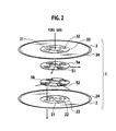
- the fuel cell unit 1 includes a metal-made cell plate 2 which forms a disc-like thin plate shape and has a gas introduction hole 21 and gas discharge holes 22 in a center portion thereof. Further, the fuel cell unit 1 includes a metal-made separator plate 3 which forms a disc-like thin plate shape and has a gas introduction hole 31 and gas discharge holes 32 in a center portion thereof in the same way as the cell plate 2. Moreover, as shown in FIG. 3, the respective outer peripheral edges of the cell plate 2 and the separator plate 3 are bonded to each other in a state where the cell plate 2 and the separator plate 3 are opposed to each other. In a bag portion (space) S formed between the cell plate 2 and the separator plate 3, a current collector 4 is housed.
- step portions 23 and 33 are formed by press work, respectively.
- the step portions 23 and 33 form concentric shapes with the outer peripheral edges of the cell plate 2 and the separator plate 3, and protrude in a direction of being separated from each other, thereby functioning as spacers as will be described later.
- annular steps 24 and 34 are formed by press work, respectively.
- the annular steps 24 and 34 form concentric shapes with the respective outer peripheral edges, and protrude in a direction of being approached to each other, thereby forming the space S.
- the gas introduction holes 21 and 31 and the gas discharge holes 22 and 32 are arranged in the respective step portions 23 and 33 of the cell plate 2 and the separator plate 3.
- Each cell 6 may be any of an electrolyte support type cell shown in FIG. 4B, an electrode support type cell shown in FIG. 4C, and a porous material support type cell shown in FIG. 4D.
- the electrolyte support type cell the one can be used, in which a cathode 6a and an anode 6c are provided on both surfaces of a solid electrolyte 6b, and the cathode 6a and the anode 6c are supported by the solid electrolyte 6b.
- the electrode support type cell the one can be used, in which the solid electrolyte 6b and the cathode 6a are provided on the anode 6c, and the cathode 6a and the solid electrolyte 6b are supported by the anode 6c.
- the porous material support type cell the one can be used, in which the cathode 6a, the solid electrolyte 6b and the anode 6c are provided on a porous plate 6d, and the cathode 6a, the solid electrolyte 6b and the anode 6c are supported by the porous plate 6d.
- a flow passage part 5a which includes a gas introduction flow passage 51 communicating with the gas introduction hole 31 and supplies fuel gas into the space S.
- a flow passage part 5b which includes a gas discharge flow passage 52 communicating with the gas discharge holes 22 and discharges the fuel gas from the space S.
- a rolled plate of stainless steel (SUS430) with a thickness of 0.1 mm is used for each of the cell plate 2 and the separator plate 3. Then, the rolled plate is set on a press machine equipped with a superhard metal die made of die steel SKD11, and is applied with a press load of 80 tons, thereby being subjected to the press work.
- SUS430 stainless steel
- An outer diameter of the cell plate 2 and the separator plate 3 which are obtained by the press work is 125 mm. Subsequently, the respective outer peripheral edges of the cell plate 2 and the separator plate 3 are bonded to each other by using laser welding, and the fuel cell unit 1 with a thickness of 1.5 mm is thus formed. Moreover, for the current collector 4 housed in the space S between the cell plate 2 and the separator plate 3, the one formed of a metal mesh made of Inconel is used, and a peripheral edge portion thereof is bonded to the cell plate 2 and the separator plate 3 by the laser welding.
- the SUS430 is used.
- the flow passage parts 5a and 5b are fixed to the cell plate 2 and the separator plate 3 by diffused junction in vacuum, where a bonding temperature is set at 1000°C or less, thereby being prevented from deformation at a time of the bonding thereof.
- a bonding temperature is set at 1000°C or less, thereby being prevented from deformation at a time of the bonding thereof.
- each of the cell plate 2 and the separator plate 3 forms the thin plate shape, and accordingly, the flow passage parts 5a and 5b can be bonded to the cell plate 2 and the separator plate 3 also by irradiating the laser thereonto from surfaces of the cell plate 2 and the separator plate 3.
- flow passage patterns of the flow passage parts 5a and 5b can be formed not only by etching, grinding processing and laser processing but also by stacking and bonding etching parts.
- the stack structure 11 is composed by stacking the above-described fuel cell units 1 to forty layers at an interval of 1.5 mm. Note that FIG. 1C shows the stack structure 11 while omitting the layers to five layers. Moreover, the plurality of stacked fuel cell units 1 are sandwiched vertically by flanges 13 and 14. Specifically, a plurality of stud bolts (not shown) are individually inserted into the plurality of gas discharge ports 22 and 32 formed around the respective gas introduction ports 21 and 31 of the cell plate 2 and the separator plate 3. Then, one end portion of each stud bolt is screwed into the upper flange 13.
- a nut is screwed with a disc spring into the other end portion of each stud bolt, which protrudes outside from the lower flange 14.
- the fuel cell units 1 stacked on one another are fastened to one another.
- the upper flange 13 includes an introduction pipe 13a for the fuel gas
- the lower flange 14 includes an exhaust pipe 14a for the fuel gas.
- a ceramic-based adhesive 17 as a seal bonding material is coated in a double-ring shape.
- the seal bonding material there can be used a glass-based adhesive and a gasket molded by adding ceramic fiber and filler to glass.
- the cells 6 form the doughnut shape as will be described later, it is possible to use a paste-like adhesive mixed with metal powder, a gasket-like brazing material, and a metal gasket.
- the above-described stack structure 11 is enclosed by the SUS430-made casing 12 which is vertically split.
- the gas introduction portion 12a and the gas discharge portion 12b are individually welded to the casing 12, and the stack structure 11 is thus housed in the casing 12.
- a filler material 16 as a gas flow-regulating member made of fireproof foaming cement is provided in a gap between the stack structure 11 and the casing 12.
- the air introduced from the gas introduction portion 12a is adapted to flow to the gas discharge portion 12b through the current collectors 15 located between the fuel cell units 1 in the stack structure 11.
- the filler material 16 is coated on an outer peripheral edge of the stack structure 11 before the stack structure 11 is housed in the casing 12.
- boron nitride as a mold release agent is sprayed in advance to the outer peripheral edge of the stack structure 11, thereby allowing a mutual movement between the filler material 16 and the stack structure 11.
- the air when the air is introduced from the gas introduction portion 12a to the casing 12 as shown in FIG. 1A to FIG. 1C, the air flows between the fuel cell units 1 of the stack structure 11, that is, to the current collectors 15 located on the cathodes side. Then, the air is exhausted through the gas discharge portion 12b. Meanwhile, the fuel gas is introduced into the respective spaces S through the introduction pipe 13a of the flange 13 and the respective gas introduction holes 21 and 31 of the fuel cell units 1. Then, the fuel gas flows through the spaces S. Subsequently, the fuel gas is exhausted through the respective gas discharge holes 22 and 32 and the exhaust pipe 14a of the flange 14.
- the filler material 16 made of the foaming cement, which serves as the gas flow-regulating member, is provided in the gap between the stack structure 11 and the casing 12. Therefore, it becomes easier for the air introduced from the gas introduction portion 12a to flow through the current collectors 15 than through the gap between the casing 12 and the stack structure 11. Hence, an air supply amount to the cells 6 held by the cell plates 2 will be increased to a great extent, resulting in that sufficient generated power can be obtained.
- the fuel gas is adapted to flow only through the spaces S each of which is formed between the cell plate 2 and separator plate 3 of the fuel cell unit 1, and accordingly, it is possible to collect unburned gas. Hence, even if the gas flow is changed at such a time when the fuel cell is under transient operation, a fuel utilization does not drop. In addition, there is a decreased possibility that a local thermal stress is applied to the cells 6, causing a malfunction thereof.
- the filler material 16 made of the foaming cement is coated on the outer peripheral edge of the stack structure 11, and the gas flow-regulating member is thus formed.
- the boron nitride as a mold release agent is sprayed in advance to the outer peripheral edge of the stack structure 11, and the surface treatment is thereby performed therefor. Therefore, the filler material 16 can be placed at a predetermined position without being adhered onto the fuel cell units 1. As a result, only by doing simple work, it becomes possible to increase a gas supply amount to the cells 6. In addition, it becomes easy for the fuel cell units 1 to release the stress by the outer peripheral edges thereof against temperature rise and drop, and the fuel cell units 1 improve thermal shock resistance thereof and make themselves thinner.
- the cell plate 2 and the separator plate 3 form mutually the same shape, however, the present invention is not limited to this.
- the cell plate 2 onto which the cell 6 is attached may form a shape only having the step portion 23, and the separator plate 3 may form a shape having the annular step 34 of which height is approximately double that in the casing of FIG. 3.
- this embodiment shows the casing where the cell 6 forms a small-diameter disc shape
- the present invention is not limited to this.
- a cell 6A forms a doughnut shape as shown in FIG. 6A
- an inner ring 7 and an outer ring 8 which have been subjected to the press work, can be bonded to inner and outer peripheral edges thereof, respectively.
- the inner ring 7 and the outer ring 8 can be bonded to the separator plate 3.
- the inner ring 7 and the outer ring 8 may be coupled to each other by bars 9 to form a frame in consideration for workability at the time of bonding. It is also possible to attach cells 6B of a sector shape to the frame.
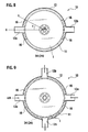
- This embodiment shows the casing where an opening shape of the casing 12 forms the circular shape, however, the present invention is not limited to this.
- the opening shape of the casing 12 may form a hexagonal shape.
- the filler material 16 is disposed over the entire periphery excluding the gas introduction portion 12a and the gas discharge portion 12b in the gap between the casing 12 and the stack structure 11.
- the filler material 16 may be provided only in the vicinity of the gas introduction portion 12a and the vicinity of the gas discharge portion 12b in the gap.
- an angel R made by a line X-O which connects a center X of the gas introduction portion 12a (gas discharge portion 12b) and a center O of the fuel cell units 1 to each other and by a line O-Y which connects the center O of the fuel cell units 1 and a terminal end of the disposed filler material 16 to each other be 15° or more.
- the angle R is less than 15°, it sometimes happens that a large amount of the gas flows through the gap between the casing 12 and the stack structure 11 to decrease a gas utilization, thereby deteriorating power generation efficiency.
- This embodiment shows the casing where the number of each of the gas introduction portion 12a and the gas discharge portion 12b is set at one, however, the present invention is not limited to this.
- two gas introduction portions 12a and two gas discharge portions 12b may be disposed on the casing 12.
- this embodiment shows the casing where the stack structure 11 of which number is one is housed, however, the present invention is not limited to this, either.
- FIG. 10 a construction may be adopted, in which three stack structures 11 are housed in the casing 12 which forms an approximately triangle shape and has three gas introduction portions 12a and one gas discharge portion 12b.
- FIG. 11 to FIG. 13B show another embodiment of the fuel cell according to the present invention.
- the gas flow-regulating member is composed by coating the filler material 16 made of the foaming cement onto a sheet material 46 made of a felt sheet.
- the sheet material 46 is located on the stack structure 11 side, mainly contains glass fiber, has electrically insulating property, and has a thickness of 0.1 mm.
- the sheet material 46 and the filler material 16 are provided only in the vicinity of the gas introduction portion 12a and the vicinity of the gas discharge portion 12b in the gap.
- the casing 12 of the fuel cell 10 includes recessed portions (positioning/holding structures) 12c toward the stack structure 11 side on four spots of an outer peripheral wall thereof.
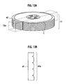
- the casing 12 includes partition walls (partition members) 47 which are located between the gas introduction portion 12a (gas discharge portion 12b) and the stack structure 11. The partition walls 47 have irregular portions 47a engaged with the outer periphery of the stack structure 11.
- Each of the recessed portions 12c is arranged on a region where an angle R made by a line O-Y which connects the recessed portion 12c and the center O of the fuel cell units 1 to each other and by a line X-O which connects the center X of the gas introduction portion 12a (gas discharge portion 12b) and the center O of the fuel cell units 1 to each other becomes approximately 45°.
- the above-described sheet material 46 and the filler material 16 are provided only between the recessed portion 12c and the partition walls 46.
- the sheet material 46 and the filler material 16 which serve as the gas flow-regulating member are provided between the stack structure 11 and the casing 12. Therefore, it becomes easier for the air introduced from the gas introduction portion 12a to flow through the current collectors 15 between the fuel cell units 1 than through the gap between the casing 12 and the stack structure 11. Therefore, the air supply amount to the cells 6 held by the cell plate 2 will be increased to a great extent. Hence, the sufficient generated power can be obtained.
- the gas flow-regulating member is composed by coating the filler material 16 made of the foaming cement onto the sheet material 46 which is located on the stack structure 11 side and has the electrically insulating property. Therefore, the filler material 16 and the fuel cell units 1 are inhibited from being adhered and fused to each other, and the thermal shock resistance of the fuel cell units 1 will be improved. In addition, it becomes possible to improve electrically insulating property between the fuel cell units 1 or between the fuel cell units 1 and the casing 12. As a result, a leakage loss is restricted, leading to the improvement of the power generation efficiency.
- the sheet material 46 which is made of the felt sheet with a small porosity, is provided only in the vicinity of the gas introduction portion 12a and the vicinity of the gas discharge portion 12b. Specifically, the sheet material 46, in which thermal conductivity is high and weight is large, is disposed restrictively to the minimum necessary amount. Accordingly, a weight reduction and a heat capacity reduction in the fuel cell 10 are achieved. In addition, since the sheet material 46 is disposed a little, heat radiation from the casing 12 is restricted, thus making it possible to improve heat insulating performance thereof. Accordingly, it becomes easier to keep the stack structure 11 warm, and the power generation efficiency will be further improved.
- the partition walls 47 are provided between the gas introduction portion 12a (gas discharge portion 12b) and the stack structure 11.
- the gas flow-regulating member is composed by coating the filler material 16 made of the foaming cement onto the sheet material 46 made of the felt sheet which is located on the stack structure 11 side and has the electrically insulating property.
- the present invention is not limited to this.
- the gas flow-regulating member may be composed in such a manner that a periphery of each current collector 15 between the fuel cell units 1 is covered with a sheet material 56 made of metal foil and that the filler material 16 is coated on each sheet material 56.
- the member with a small porosity such as the ceramic felt sheet and the metal foil
- a porosity of the filler material injected or coated between the casing 12 and the stack structure 11 can be increased. Therefore, the improvement of the heat insulating performance and the weight reduction are achieved.
- cracks are difficult to enter the filler material against the thermal shock, and even if the cracks enter, the decrease of the gas flow regulating performance will be avoided.
- the partition walls 47 are provided between the gas introduction portion 12a (gas discharge portion 12b) and the stack structure 11.
- baffle members 47b can be provided integrally with each partition wall 47.
- buffer portions 47c can be provided by bending each partition wall 47.
- the baffle members 47b are provided integrally with the partition wall 47, on the gas introduction portion 12a side, the air introduced therefrom can be flown smoothly through the current collectors 15. Moreover, on the gas discharge portion 12b side, the air which has passed through the current collectors 15 can be guided smoothly to the gas discharge portion 12b. As a result, it becomes possible to easily distinguish the gas introduction portion 12a and the gas discharge portion 12b, of which pressure losses are desired to be reduced, and the region with a small porosity, of which pressure loss is desired to be increased.
- the buffer portions 47c are provided on the partition wall 47, it is possible to absorb a large resonance of the peripheral edge portions of the fuel cell units 1 owing to mechanical vibrations of the fuel cell 10, and accordingly, excellent durability is brought.
- FIG. 16A and FIG. 16B show still another embodiment of the fuel cell according to the present invention.
- a molded body 66 matched with the shape of the gap is used as the gas flow-regulating member provided in the gap between the stack structure 11 and the casing 12.
- the molded body 66 is composed by performing stamp molding for felt into a semi-annular shape so that the felt can be matched with the outer diameter of the fuel cell units 1.
- the felt is formed by mixing an organic binder into alumina fiber and mica powder which are main components.
- the molded body 66 has steps each of which has a thickness equivalent to an interval between the fuel cell units 1. The step is formed by a hot-press machine so as to be matched with the outer peripheral edge of the fuel cell unit 1.
- the casing 12 forms a cylindrical shape which has the flange 14 fixed to a bottom portion thereof and is open at an upper end thereof, and the gas introduction portion 12a and the gas discharge portion 12b are located on such an opening portion at the upper end.
- the stack structure 11 is inserted into the casing 12 from the upper end opening thereof in a state where the molded body 66 which forms the semi-annular shape is set between the fuel cell units 1.
- the casing 12 which houses the stack structure 11 therein is hermetically sealed by welding the flange 13 and a top cover to the upper end opening.
- a heat treatment is performed for the fuel cell 10 while introducing the air into the casing 12, thereby burning off the organic component of the molded body 66 set in the ring shape between the fuel cell units 1.
- elasticity of the felt which constructs the molded body 66 is recovered, and as shown in FIG. 17, gaps surrounded by the fuel cell units 1, the current collectors 15 and the casing 12 are filled.
- the molded body 66 matched with the shape of the gap is provided in the gap between the stack structure 11 and the casing 12. Therefore, it becomes easier for the air introduced from the gas introduction portion 12a to flow through the current collectors 15 than through the gap. Hence, the air supply amount to the cells 6 held by the cell plates 2 will be increased to a great extent, resulting in that the sufficient generated power can be obtained.
- the molded body 66 matched with the shape of the gap is used as the gas flow-regulating member. Therefore, it becomes possible to constantly maintain the interval between the stacked fuel cell units 1. As a result, it is possible to evenly flow, through the respective layers of the fuel cell units 1, the air introduced into the casing 12, resulting in an improvement of an output density.
- the molded body 66 which forms the semi-annular shape is set between the fuel cell units 1.
- a felt mat 74 which is stacked on a felt sheet 75 to be then integrated therewith is used as the gas flow-regulating member.
- An integrated sheet material 76 composed of the felt mat 74 and the felt sheet 75 has horizontal stripe-like irregularities formed by press-molding a portion of the felt mats 74 so that the portion can be matched with the outer peripheral edge shape of the fuel cell units 1.
- the integrated sheet material 76 can be formed so as to be wrapped around the outer peripheral portion of the stack structure 11 and to be housed in the casing 12.
- a ceramic adhesive of a room temperature curing type may be coated on the horizontal stripe-like irregularities of the integrated sheet material 76, with which the inter-unit current collectors 15 are brought into contact, followed by solidification. With providing the ceramic adhesive, it becomes possible to form a layer with a smaller porosity at a position where surfaces of the felt mats 74 and the current collectors 15 are brought into contact with each other.
- the molded body 66 which forms the semi-annular shape is set between the fuel cell units 1, thereby constantly maintaining the interval between the stacked fuel cell units 1.
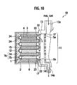
- the gas flow-regulating member is formed of a wavy thin plate (spacer) 86 and a filler material 87 which are for constantly maintaining the interval between the fuel cell units 1.
- spacer spacer
- filler material 87 which are for constantly maintaining the interval between the fuel cell units 1.
- the molded body 66 is set between the fuel cell units 1 of the stack structure 11 over the entire peripheries thereof.
- the partition walls 47 which integrally have the baffle members 47b as less porous portions of the gas flow-regulating member can be arranged in the vicinity of the gas introduction portion 12a and the vicinity of the gas discharge portion 12b.
- the angel R made by the line X-O which connects the center X of the gas introduction portion 12a (gas discharge portion 12b) and the center O of the fuel cell units 1 to each other and by the line O-Y which connects the center O of the fuel cell units 1 and a terminal end of the baffle members 47b of each partition wall 47 be set to at least 15°.
- the baffle members 47b be brought into contact with the current collectors 15, and that the partition walls 47 be made adjacent to the gas introduction portion 12a (gas discharge portion 12b).
- the baffle members 47 which are highly conductive and heavy are restricted to the minimum necessary, and the weight reduction and the heat capacity reduction in the fuel cell 10 will be achieved.
- the heat radiation from the casing 12 is restricted, thus making it possible to improve the heat insulating performance thereof. Accordingly, it becomes easy to keep the stack structure 11 warm, and the power generation efficiency will be improved.
- a porosity of a portion of the gas flow-regulating member, which is located on the casing 12 side be set larger than a porosity of a portion thereof, which is located on the stack structure 11 side.
- a dense surface layer 66a with a small porosity in such a manner that, when the molded body 66 matched with the shape of the gap between the casing 12 and the stack structure 11 is used as the gas flow-regulating member, the ceramic-based adhesive is coated on the outer peripheral surface of the molded body 66, followed by the solidification.
- a construction example to partially change the porosity of the gas flow-regulating member can be composed in such a manner that a sheet material 96 coated with a gel filler material 97 is wrapped around the stack structure 11, the filler material 97 is solidified, and then the stack structure 11 is housed in the casing 12.
- the construction may be composed so as to stack a filler material 98 with a smaller porosity than that of the filler material 97 of the sheet material 96 thereon. If the construction is composed so as to pattern plural layers of the filler materials different in porosity from each other on the sheet material 96, then it becomes possible to simply control the porosity of the gas flow-regulating member. As described above, if the filler materials different in porosity from each other are stacked into desired patterns by a printing technology, then it becomes possible to cope with a complicated peripheral shape of the stack structure.
- a construction example to partially change the porosity of the gas flow-regulating member can be composed so as to dispose a molded body 107 with a large porosity on the outside of the molded body 106 with a small porosity.
- the heat radiation from the casing 12 is restricted, thus making it easy to keep the stack structure 11 warm.
- the power generation efficiency will be improved.
- FIG. 24 shows yet another embodiment of the fuel cell according to the present invention.
- a portion of each current collector 115 on the casing 12 side is formed as a dense portion (gas flow-regulating member) 116 with a small porosity.
- the dense portion is capable of maintaining the interval between the fuel cell units 1.
- electrically insulating members 117 formed of felt sheets made of glass fiber are interposed between the dense portions 116 and the fuel cell units 1 and between the dense portions 116 and the casing 12. Note that the dense portions 116 are not formed on portions of the current collectors 115, which are opposite to the gas introduction portion 12a and the gas discharge portion 12b.
- knitted strings which are made of metal fiber and arrayed into a doughnut shape, are formed to a desired thickness by hot-press molding, thereby forming the current collectors 115. Moreover, at a stage where the knitted strings are arrayed into the doughnut shape, the knitted strings are stacked and arranged more on outer peripheral portions of the current collectors 115 than on center portions thereof with which the cells 6 are brought into contact. Thus, the dense portions 116 with a small porosity are integrally formed on the outer peripheral portions of the current collectors 115.
- the electrically insulating members 117 are arranged on both surfaces and outer peripheral portions of the dense portions 116 of the current collectors 115. Subsequently, the fuel cell units 1 are stacked on one another while interposing the current collectors 115 therebetween to form the stack structure 1, and then the stack structure 11 is housed in the casing 12. Hence, in the fuel cell 10, it is possible to maintain the interval between the fuel cell units 1 by the dense portions 116 of the current collectors 115, and accordingly, assembly work thereof becomes easy.
- the dense portions 116 formed integrally with the current collectors 115 are arranged in the gap between the stack structure 11 and the casing 12. Therefore, it becomes easier for the air introduced from the gas introduction portion 12a to flow through the center portions of the current collectors 15 than through the gap between the casing 12 and the stack structure 11. Therefore, the air supply amount to the cells 6 held by the cell plate 2 will be increased to a great extent, and hence, the sufficient generated power can be obtained.
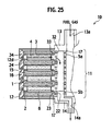
- FIG. 25 shows still yet another embodiment of the fuel cell according to the present invention.
- the fuel cell 10 of this embodiment there is provided, in the casing 12, ratchet-like steps 12d as a positioning/holding structure.
- the ratchet-like steps 12d locate and hold the stack structure 11 at a predetermined region in the casing 12.
- Other constructions are the same as those of the fuel cell 10 in the previous embodiment shown in FIG. 1.
- This embodiment shows the casing where the ratchet-like steps 12d are used as the positioning/holding structure.
- the present invention is not limited to this.
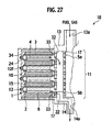
- FIG. 26 another construction can be adopted, in which wavy steps 12e are used as the positioning/holding structure, and as shown in FIG. 27, still another construction can be adopted, in which wedge-shaped grooves 12f are used as the positioning/holding structure.
- this embodiment shows the casing where each of the ratchet-like steps 12d, the wavy steps 12e and the wedge-shaped grooves 12f is formed so as to correspond to all the fuel cell units 1.
- the ratchet-like steps 12d, the wavy steps 12e and the wedge-shaped grooves 12f may be formed partially or entirely on the outer periphery of the casing 12, or may be formed to every plural fuel cell units 1.
- the fuel cell according to the present invention is characterized in that the gas flow-regulating member is provided in the gap between the casing and the stack structure. Moreover, the gas flow-regulating member is formed of the highly porous material, thus making it possible to enhance the heat retaining property of the stack structure.
- the gas flow-regulating member can be formed of a material with a high heat radiation property. In this case, even if the stack structure is in an abnormally high temperature state, the stack structure can be cooled efficiently. As such a material, a material with high radiant efficiency and a material with high heat transfer efficiency can be used.
Landscapes
- Life Sciences & Earth Sciences (AREA)
- Engineering & Computer Science (AREA)
- Manufacturing & Machinery (AREA)
- Sustainable Development (AREA)
- Sustainable Energy (AREA)
- Chemical & Material Sciences (AREA)
- Chemical Kinetics & Catalysis (AREA)
- Electrochemistry (AREA)
- General Chemical & Material Sciences (AREA)
- Fuel Cell (AREA)
Abstract
Description
- The present invention relates to a fuel cell composed by housing, in a casing, a stack structure formed by stacking a plurality of solid oxide fuel cell units on one another.
- Heretofore, as a fuel cell including a stack structure formed by stacking a plurality of solid oxide fuel cell units, there is one disclosed in
United States Patent No. 6,344,290 . - In the case of this fuel cell, both gases which are fuel gas and air are supplied thereto from center portions of cell plates and to be discharged from outer peripheral portions of the cell plates. Accordingly, unburned gas cannot be collected. As a result, when a gas flow is changed at such a time when the fuel cell is under transient operation, a fuel utilization drops to decrease a coefficient thereof. In addition, combustion of the fuel in the outer peripheral portions becomes unstable. Therefore, there is an apprehension that a local thermal stress is applied to each cell, causing a breakage thereof.
- In this connection, as a fuel cell composed in order to solve such an apprehension as described above, there is one described in
Japanese Patent Unexamined Publication No. 2004-207028 - In the fuel cell described in
Japanese Patent Unexamined Publication No. 2004-207028 - Moreover, the fuel cell described above includes a stack structure composed by fastening the respective center portions of the plurality of fuel cell units stacked on one another. Accordingly, the respective outer peripheral edges of the fuel cell units are not fixed, and are placed in a free state. Therefore, the fuel cell has a less breakable construction against thermal shock caused by quick heating and the like. However, when mechanical vibrations are applied entirely to the fuel cell as in the case where the fuel cell is mounted on a vehicle, there has been an apprehension that the respective outer peripheral edges of the fuel cell units vibrate resonantly to apply a mechanical stress to the cells, causing a malfunction such as a crack.
- The present invention has been made in consideration for the problems as described above inherent in the related art. It is an object of the present invention to provide a fuel cell which is, even if there is a gap between the casing and the stack structure, capable of obtaining sufficient generated power, and in addition, capable of enhancing durability thereof against the mechanical vibrations.
- According to one aspect of the present invention, there is provided a fuel cell including: a stack structure composed by stacking a plurality of solid oxide fuel cell units with current collectors, each of the fuel cell unit including: a cell plate which holds at least one cell and has a gas introduction hole for one of fuel gas and air in a center portion thereof; and a separator plate which has a gas introduction hole for the one of the fuel gas and the air in a center portion thereof and makes an outer peripheral edge thereof entirely bonded to an outer peripheral edge of the cell plate; a casing housing the stack structure, the casing including a gas introduction portion and a gas discharge portion, and the casing introducing the other of the fuel gas and the air thereinto from the gas introduction portion and flowing the other gas to the gas discharge portion; and a gas flow-regulating member provided in a gap between the casing and the stack structure in order to flow the other gas to the gas discharge portion through the current collectors located between the fuel cell units
- The invention will now be described with reference to the accompanying drawings wherein;
- FIG. 1A is a perspective view showing an embodiment of a fuel cell according to the present invention;
- FIG. 1 B is a plan view showing a state where an upper surface of a casing and an uppermost current collector are removed in the embodiment of the fuel cell according to the present invention;
- FIG. 1C is a cross-sectional view showing the fuel cell of FIG. 1A, taken along a line IC-IC of FIG. 1B;
- FIG. 2 is an exploded perspective view showing a fuel cell unit constructing a stack structure of the fuel cell in FIG. 1A;
- FIG. 3 is a partial cross-sectional view showing the fuel cell unit of the fuel cell in FIG. 1A;
- FIG. 4A is a plan view of a cell plate, showing an arrangement pattern of cells of the fuel cell in FIG. 1A;
- FIG. 4B is a cross-sectional view showing an example of an electrolyte support type cell;
- FIG. 4C is a cross-sectional view showing an example of an electrode support type cell;
- FIG. 4D is a cross-sectional view showing an example of a porous material support type cell;
- FIG. 5 is a partial cross-sectional view showing another construction of the fuel cell unit in the fuel cell of FIG. 1A;
- FIGS. 6A and 6B are plan view of cell plates, showing other arrangement patterns of the cells in the fuel cell of FIG. 1A;
- FIG. 7 is a plan view in a state where an upper surface of a casing and the uppermost current collector are removed, showing a modification example of the casing of the fuel cell in FIG. 1A;
- FIG. 8 is a plan view in a state where the upper surface of the casing and the uppermost current collector are removed, showing an arrangement example of a gas flow-regulating member in the fuel cell of FIG. 1A;
- FIG. 9 is a plan view in a state where an upper surface of a casing and the uppermost current collector are removed, showing another modification example of the casing;
- FIG. 10 is a plan view in a state where the upper surfaces of the casing and the uppermost current collectors are removed, showing a state where a plurality of the stack structures are housed in the casing;
- FIG. 11 is a plan view in a state where the upper surface of the casing and the uppermost current collector are removed, showing another embodiment of the fuel cell according to the present invention;
- FIG. 12 is a cross-sectional view showing the fuel cell of another embodiment, taken along a line XII-O of FIG. 11;
- FIG. 13A is a perspective view showing a part of the fuel cell in FIG. 11;
- FIG. 13B is a front view showing a partition wall;
- FIG. 14 is a cross-sectional view showing a part of the fuel cell in FIG. 11;
- FIGS. 15A and 15B are schematic views showing modification examples of the partition wall;
- FIG. 16A is a plan view in a state where the upper surface of the casing and the uppermost current collector are removed, showing a still another embodiment of the fuel cell according to the present invention;
- FIG. 16B is a cross-sectional view showing the fuel cell of the still another embodiment, taken along a line XVIB-XVIB of FIG. 16A;
- FIG. 17 is a partial cross-sectional view showing a state after burning off an organic component of a molded body as the gas flow-regulating member in the fuel cell of FIG. 16A;
- FIG. 18 is a partial cross-sectional view showing another modification example of the fuel cell in FIG. 16A;
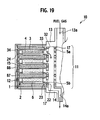
- FIG. 19 is a partial cross-sectional view showing still another modification example of the fuel cell in FIG. 16A;
- FIG. 20 is a plan view in a state where the upper surface of the casing and the uppermost current collector are removed, showing another modification example of the fuel cell in FIG. 16A;
- FIG. 21 is a partial cross-sectional view showing yet another modification example of the fuel cell in FIG. 16A;
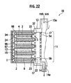
- FIG. 22 is a partial cross-sectional view showing still yet another modification example of the fuel cell in FIG. 16A;
- FIG. 23 is a partial cross-sectional view showing another modification example of the fuel cell in FIG. 16A;
- FIG. 24 is a partial cross-sectional view showing yet another embodiment of the fuel cell according to the present invention;
- FIG. 25 is a partial cross-sectional view showing still yet another embodiment of the fuel cell according to the present invention;
- FIG. 26 is a partial cross-sectional view showing another modification example of the fuel cell in FIG. 25; and
- FIG. 27 is a partial cross-sectional view showing still another modification example of the fuel cell in FIG. 25.
- Hereinafter, description will be made of embodiments of the present invention with reference to the drawings.
- A fuel cell according to the present invention includes solid oxide fuel cell units. Each of the solid oxide fuel cell units includes a cell plate which holds a cell and has a gas introduction hole for one of fuel gas and air in a center portion thereof, and a separator plate which has a gas introduction hole for the one of the fuel gas and the air in a center portion thereof and makes an outer peripheral edge thereof bonded to an outer peripheral edge of the cell plate. Moreover, a plurality of the above-described fuel cell units are stacked on one another with current collectors, thereby forming a stack structure.
- Moreover, the above-described fuel cell includes a casing. The casing includes a gas introduction portion and a gas discharge portion, and introduces the other of the fuel gas and the air thereinto from the gas introduction portion and flows the other gas to the gas discharge portion in a state of housing the stack structure therein.
- In the above-described fuel cell, the one of the fuel gas and the air is supplied from the respective gas introduction holes of the cell plate and the separator plate into the fuel cell units. The one gas supplied into the fuel cell units may be discharged from centers of the units by forming gas discharge holes in the center portions of the fuel cell units, or may be discharged from outer peripheries of the units by forming notches for discharging the gas on outer peripheral edges of the fuel cell units.
- Moreover, the present invention is characterized in that a gas flow-regulating member is provided in a gap between the casing and the stack structure in order to flow the other gas to the gas discharge portion through the current collectors located between the fuel cell units of the stack structure, the other gas being introduced into the casing from the gas introduction portion. With providing the gas flow-regulating member, it becomes easier for the other gas introduced from the gas introduction portion of the casing to flow through a portion of the current collectors between the fuel cell units stacked on one another in the stack structure than through the gap between the casing and the stack structure. Therefore, a supply amount of the other gas to the cells held by the cell plates will be increased to a great extent, resulting in that sufficient generated power can be obtained.
- In the fuel cell of a type which discharges, from the outer peripheral edges of the fuel cell units, the one gas supplied into the fuel cell units, the discharge of the one gas from the gas discharge portion of the casing can be restricted by the gas flow-regulating member. Therefore, it becomes possible to prevent a backfire to the fuel cell units at a time when the fuel cell is under transient operation. As a result, it is possible to perform a stable operation, and it becomes possible to avoid a thermal shock.
- Moreover, in the present invention, a thickness of the center portion of each fuel cell unit is made larger than a thickness of a region thereof where the cell is installed, thereby giving a function of a spacer to the center portion. Thus, between the stacked fuel cell units, flow passages through which the other of the fuel gas and the air is flown are formed.
- Each fuel cell unit in the fuel cell according to the present invention is composed by bonding the respective outer peripheral edges of the cell plate and the separator plate to each other. Specifically, a step along the outer peripheral edge is provided in at least one of the cell plate and the separator plate, and thereafter, the outer peripheral edges are bonded to each other. Thus, between the cell plate and the separator plate, there is formed a space through which the one of the fuel gas and the air flows.
- Note that, if the above-described steps are formed on both of the cell plate and the separator plate to establish symmetry therebetween, then it becomes possible to restrict a stress concentration. However, even if sizes of both of the steps are mutually changed, an improvement of strength of the cell plate and the separator plate, which may be brought by providing the steps, can be expected. Moreover, in the case of forming the step on one of the cell plate and the separator plate, a mounting area of the cell can be increased. As described above, it is possible to change the shapes of the cell plate and the separator plate in response to characteristics regarded as important, such as an improvement of thermal shock resistance and an improvement of an output density.
- In the present invention, it is desirable that the steps provided on the cell plate and separator plate of the fuel cell unit be formed by press work. Furthermore, for bonding the respective outer peripheral edges of the cell plate and the separator plate to each other, not only welding and brazing can be used, but also ultrasonic bonding and the like can be used.
- In the present invention, attachment positions of the cells of the fuel cell unit can be set in a region which forms a doughnut shape between the center portion and outer peripheral edge of the cell plate. One or more cells can be fixed into the region which forms the doughnut shape. For example, when the cell forms a small-diameter disc shape, it is desirable that the cells be arranged regularly around the center of the cell plate. Moreover, when the cell forms the doughnut shape, it is desirable that an inner ring and an outer ring, which have been subjected to the press work, be bonded to inner and outer peripheral edges of the cell, respectively. Moreover, the inner ring and the outer ring may be coupled to each other to form a frame shape, and it is also possible to attach cells of a sector shape to the frame.
- Moreover, in the present invention, the stack structure is composed by stacking the plurality of fuel cell units, and gas seal bonding layers are interposed between the respective center portions of the fuel cell units stacked on one another. In this case, as the gas seal bonding layers, not only an inorganic bonding material such as a ceramic-based adhesive and a glass-based adhesive which have electrically insulating property can be used, but also a conductive bonding material mixed with a brazing material and metal powder, and gasket seal layers can be used, for example, when the cells form the doughnut shape.
- Furthermore, in the stack structure, inter-unit current collectors are interposed between the respective cell regions of the fuel cell units. As the inter-unit current collectors, conductive porous bodies can be used. For example, not only metal mesh and foaming metal can be used, but also fabric and felt of fiber made of metal or an electrode material can be used.
- Moreover, in a fuel cell of a type which discharges, from the centers of the fuel cell units, the one gas supplied into the fuel cell units, the stack structure is formed in such a manner that a flange, which includes an introduction pipe supplying the one gas into the fuel cell units, and a flange, which includes an exhaust pipe discharging the one gas from the fuel cell units, are installed on and under the stacked fuel cell units.
- In the present invention, a plan shape of the fuel cell unit which forms the stack structure and an opening shape of the casing which houses the stack structure therein are not limited to the circular shape, and for example, may be a quadrangular shape, a polygonal shape, and a cloudy shape.
- Moreover, when the stack structure and the casing form a cylindrical shape, the gas introduction portion and gas discharge portion of the casing can be arranged toward a side surface of the stack structure, and can be arranged toward upper and lower surfaces of the stack structure.
- In the present invention, the number of stack structure housed in the casing is not limited to one, and a construction in which a plurality thereof are housed may be adopted. Moreover, the number of each of the gas introduction portion and gas discharge portion of the casing is not limited to one, and a plurality of each thereof can also be installed.
- Moreover, for the above-described gas flow-regulating member, there can be used: an indefinite material which includes a castable refractory, fireproof foaming cement such as portland cement, alumina cement, phosphate cement, and silicate cement, fireproof mortar, gypsum, a ceramic adhesive, and bubble glass; and a sheet material or a molded body which includes felt, fabric, and knit which are mainly composed of glass fiber, ceramic fiber, and metal fiber, a composite material thereof, and metal foil. The gas flow-regulating member is not limited to any of the above.
- Note that, for the purpose of improving thermal conductivity of the gas flow-regulating member and promoting heat radiation from the casing, the above-described gas flow-regulating member can be formed of a composite material obtained by mixing thereinto filler which is particulate, fibrous, chip-like, and so on, the filler being made of metal or ceramics, which is good in thermal conductivity.
- Meanwhile, for the purpose of improving heat insulating performance of the gas flow-regulating member, restricting the heat radiation from the casing, and adjusting a porosity of the gas flow-regulating member, the gas flow-regulating member can also be composed of a porous body by mixing and molding thereinto an organic material and carbon filler, followed by firing.
- In the present invention, when the stack structure and the casing form a cylindrical shape, an installed position of the gas flow-regulating member depends on stack specifications such as the number of gas introduction portion and gas discharge portion of the casing, a ratio of an outer diameter of the fuel cell units and a diameter of the center portions thereof, an interval between the fuel cell units, opening widths of the gas introduction portion and gas discharge portion of the casing, a ratio in porosity of the inter-unit current collectors and the gas flow-regulating member, and an output density of the cells. Besides the above, the above-described installed position also depends on operation conditions such as a gas flow rate and an operation temperature. However, in the present invention, a construction can be adopted, in which the gas flow-regulating member is provided only in the vicinity of the gas introduction portion of the casing and the vicinity of the gas discharge portion thereof. In this case, as shown in FIG. 8, it is preferable that an angel R made by a line X-O which connects a center X of the
gas introduction portion 12a (gas discharge portion) of thecasing 12 and a center O of thefuel cell units 1 to each other and by a line O-Y which connects the center O of thefuel cell units 1 and a terminal end of the disposed gas flow-regulatingmember 16 be 15° or more. When the angle R is less than 15°, it sometimes happens that a large amount of gas flows through the gap between thecasing 12 and thestack structure 11 to decrease a gas utilization, thereby deteriorating power generation efficiency. Note that, as a matter of course, the gas flow-regulatingmember 16 may be disposed over the entire periphery of the gap excluding thegas introduction portion 12a and thegas discharge portion 12b. - Moreover, in the present invention, a construction can be adopted, in which the gas flow-regulating member and the respective fuel cell units of the stack structure are mutually movably brought into contact with each other. When the gas flow-regulating member and the fuel cell units are completely adhered onto each other, distortion sometimes occurs in bonded portions thereof owing to a difference in thermal expansion coefficient between the materials constructing the respective members. However, if the above-described construction is adopted, it becomes easy for the fuel cell units to release a stress at the outer peripheral edges thereof against temperature rise and drop. As a result, the fuel cell units will improve the thermal shock resistance thereof and make themselves thinner. Further, a stack structure with a low heat capacity, which is excellent in starting easiness and responsiveness, can be obtained.
- In the present invention, the gas flow-regulating member can be composed of a filler material injected or coated into the gap between the casing and the stack structure. In this case, if an oil-based material or a mold release agent is coated in advance on the fuel cell units side, then the filler material as the gas flow-regulating member can be disposed at a predetermined position without being adhered onto the fuel cell units. When such a construction is adopted, a gas supply amount to the portion of the cells is increased only by performing simple work, thereby improving the output density.
- Moreover, the gas flow-regulating member can be composed of a molded body matched with a shape of the gap between the casing and the stack structure. In this case, for the molded body, the composite material of the indefinite material and the felt, the fabric, and the knit can be used. In a stacking step of the fuel cell units, while disposing the above-described molded body between the fuel cell units, other parts are stacked on one another, thereby forming the stack structure. The gas flow-regulating member is composed of the molded body matched with the shape of the gap between the casing and the stack structure, thus making it possible to constantly maintain the interval between the stacked fuel cell units. As a result, it is possible to evenly flow, through the respective layers of the fuel cell units, the gas introduced into the casing, and accordingly, the output density will be improved.
- Furthermore, the above-described gas flow-regulating member can be composed by combining a sheet material located on the stack structure side and a filler material injected or coated onto the casing side. Moreover, the above-described gas flow-regulating member can be composed by combining the sheet material and the molded body matched with the shape of the gap between the casing and the stack structure. Furthermore, the above-described gas flow-regulating member can be composed by combining a spacer which is located on the stack structure side and capable of maintaining the interval between the fuel cell units and the filler material injected or coated onto the casing side.
- When the gas flow-regulating member is composed by combining the sheet material located on the stack structure side and the filler material injected or coated onto the casing side, a felt sheet which mainly contains ceramic fiber as a main component can be disposed as the sheet material between the filler material and the stack structure. Thus, the filler material and the fuel cell units are inhibited from being adhered and fused to each other, and the thermal shock resistance of the fuel cell units will be improved. Moreover, in this case, as the sheet material, there can be disposed ceramic felt, metal foil, and the like which wrap the peripheries of the inter-unit current collectors. With such a construction, at the time when the filler material is injected or coated, it is possible to inhibit the filler material from entering pores of the current collectors.
- Meanwhile, when the gas flow-regulating member is composed by combining the sheet material and the molded body matched with the shape of the gap between the casing and the stack structure, the sheet material to which the molded body is bonded can be formed so as to be wrapped around the stack structure and to be housed in the casing. Thus, it becomes possible to simply form the gas flow-regulating member and to simply install the gas flow-regulating member onto the stack structure.
- Moreover, when the gas flow-regulating member is composed by combining the spacer capable of maintaining the interval between the fuel cell units and the filler material, the gas flow-regulating member can be formed of a wavy thin plate as the spacer for constantly maintaining the inter-unit interval and of the filler material. In this case, it is possible to maintain the interval between the fuel cell units. Accordingly, it becomes possible to prevent the peripheral edge portions of the fuel cell units from resonating to a large extent against the mechanical vibrations of the fuel cell. Hence, excellent durability is brought to the fuel cell.
- In the present invention, a construction can be adopted, in which a porosity of the gas flow-regulating member is set smaller than a porosity of the current collectors located between the fuel cell units. When such a construction is adopted, the supply amount of the other of the fuel gas and the air to the cells of the fuel cell units will be further increased. Specifically, when the fuel cell is steadily operated in an operation mode with a large heat generation amount, such as a time of a high-load operation, a construction can be adopted, in which an air flow passage for cathodes are provided on the outside of the casing, the introduced air is preheated, and the stack structure is cooled. In this case, the porosity of the gas flow-regulating member is reduced, and thus heat transfer from the stack structure to the casing is promoted, and the heat can be radiated effectively to the outside of the casing. Moreover, for the purpose of promoting the heat transfer from the stack structure to the casing, and for the purpose of promoting heat transfer from the casing, the gas flow-regulating member can be composed of the composite material obtained by mixing thereinto the filler of the metal or the ceramics, which is excellent in thermal conductivity.
- Moreover, in the present invention, a construction can be adopted, in which the porosity of the gas flow-regulating member is partially changed. Specifically, in the gas flow-regulating member, a region in which the thermal conductivity is high, weight is large, and the porosity is small is restricted to the minimum necessary. Thus, a weigh reduction and a heat capacity reduction in the fuel cell will be achieved. In addition, since the heat radiation from the casing is restricted, thus making it possible to improve the heat insulating performance thereof. Accordingly, it becomes easy to keep the stack structure warm, and the power generation efficiency will be improved.
- In this case, it is preferable to adopt a construction in which a porosity of a portion of the gas flow-regulating member, which is located on the casing side, is set larger than a porosity of a portion thereof located on the stack structure side. For example, as shown in FIG. 20,
baffle members 47b, which have a small porosity, are arranged in the vicinity of thegas introduction portion 12a of thecasing 12 and the vicinity of thegas discharge portion 12b thereof. Further, the angel R made by the line X-O which connects the center X of thegas introduction portion 12a (gas discharge portion 12b) and the center O of the fuel cell units to each other and by the line O-Y which connects the center O of thefuel cell units 1 and a terminal end of thebaffle members 47b of the gas flow-regulating member to each other is set to at least 15°. Moreover, thebaffle members 47b with the small porosity are brought into contact with the inter-unitcurrent collectors 15, and apartition wall 47 including thebaffle member 47b is made to face to thegas introduction portion 12a (gas discharge portion 12b). - Moreover, as described above, when the gas flow-regulating member is composed by combining the sheet material located on the stack structure side and the filler material injected or coated on the casing side, a member with a small porosity, such as a ceramic felt sheet, metal foil, and metal mesh, can be used for the sheet material. In this case, the porosity of the filler material can be increased, and the improvement of the heat insulating performance and the weight reduction will be achieved. In addition, cracks are difficult to enter the filler material against the thermal shock, and even if the cracks enter, a decrease of the gas flow regulating performance will be avoided.
- Furthermore, as described above, when the gas flow-regulating member is composed of the molded body matched with the shape of the gap between the casing and the stack structure, the ceramic-based adhesive is coated on an outer peripheral surface of the molded body, followed by solidification, thereby forming a dense surface layer with a small porosity. Then, the weight reduction and the heat capacity reduction will be achieved.
- Moreover, as such a construction in which the porosity of the gas flow-regulating member is partially changed, a construction can be adopted, in which a member formed by coating the filler material onto the sheet material is wrapped around the periphery of the stack structure, the above-described member is solidified, and then the stack structure is housed in the casing. In this case, for example, if a member formed by patterning plural layers of the filler materials different in porosity from each other on the sheet material and coating the filler materials thereon, then it becomes possible to simply control the porosity of the gas flow-regulating member. As described above, if the filler materials different in porosity from each other are stacked into desired patterns by a printing technology, then it becomes possible to cope with a complicated peripheral shape of the stack structure.
- Furthermore, as such a construction in which the porosity of the gas flow-regulating member is partially changed, a construction can be adopted, in which a molded body and a filler material each of which has a large porosity are arranged on the outside of a molded body and a filler material each of which has a small porosity. In this case, the heat radiation from the casing is restricted, thus making it easy to keep the stack structure warm. As a result, the power generation efficiency will be improved.
- In the present invention, the peripheral edge portions of the members which construct the fuel cell units, such as the separator plates and the cell plates, can be formed of a conductive material such as metal. In this case, it is desirable that an electrically insulating layer be disposed on a portion of the gas flow-regulating member, which is brought into contact with at least the fuel cell units. Further, it is desirable that an electrically insulating treatment be implemented for the portion of the gas flow-regulating member, which is brought into contact with the fuel cell units. As described above, when the construction in which the gas flow-regulating member and the fuel cell units are electrically insulated from each other is adopted, it becomes possible to improve electrically insulating property between the fuel cell units or between the fuel cell units and the casing through the gas flow-regulating member. As a result, a leakage loss is restricted, leading to the improvement of the power generation efficiency.
- As the above-described electrically insulating layer, an electrically insulating sheet of felt, fabric, or knit, which is mainly formed of glass fiber or ceramic fiber, can be used. In this case, the one obtained by forming a ceramic adhesive layer on either surface of front and back of the insulating sheet, followed by solidification, can be located thereon, and on the surface, a glass coating layer, an enamel layer, and the like can be formed. In addition, as the filler material, a material can be used, which is superior in property such as quick drying property and porosity controllability though inferior in electrically insulating property at a high temperature.
- In the present invention, a construction can be adopted, in which a casing side portion of the current collectors located between the fuel cell units is formed as the gas flow-regulating member capable of maintaining the interval between the fuel cell units, and the electrically insulating member is interposed between the gas flow-regulating member and the fuel cell units. Specifically, for the porous current collectors, the gas flow-regulating members with a small porosity are formed in advance. Then, at the time of the stacking step of the fuel cell units, while the electrically insulating layers are being arranged on the front and back of each gas flow-regulating member as the current collector, the fuel cell units are stacked on one another with the current collectors interposed therebetween, thereby forming the stack structure. Thereafter, the stack structure is housed in the casing. In this case, it is possible to easily maintain the interval between the fuel cell units, and accordingly, assembly work of the fuel cell becomes easy.
- In the present invention, a partition member can be provided on the gas introduction portion and an end surface of the gas flow-regulating member adjacent to the gas introduction portion. Further, the partition member can be provided on the gas discharge portion and an end surface of the gas flow-regulating member adjacent to the gas discharge portion. Thus, when the gas flow-regulating members are formed of the filler material or the molded body, it becomes possible to avoid that the gas flow-regulating members will hang out to the gas introduction portion and the gas discharge portion, thereby hindering the flow of the gas.
- Moreover, partition walls can be provided as the partition members. Furthermore, on the partition wall on the gas introduction portion side, first baffle members can be provided integrally therewith. The first baffle members flow, to the current collectors between the fuel cell units, the other gas introduced from the gas introduction portion. In addition, on the partition wall on the gas discharge portion side, second baffle members can be provided integrally therewith. The second baffle members guide, to the gas discharge portion, the other gas having passed through the current collectors. In this case, it becomes possible to easily distinguish the gas introduction portion and the gas discharge portion, of which pressure losses are desired to be reduced, an the region with a small porosity, of which pressure loss is desired to be increased.
- In the present invention, a positioning/holding structure which locates and holds the stack structure at a predetermined region in the casing can be provided in the casing. The positioning/holding structure can be formed on a part of the casing. The positioning/holding structure can be formed on an entirety of the casing. Alternatively, the positioning/holding structure can be formed to every plural fuel cell units of the stack structure.
- Specifically, the positioning/holding structure can be composed of ratchet-like steps, wavy steps, and wedge-shaped grooves. Moreover, when the casing and the stack structure form the cylindrical shape, the positioning/holding structure can be formed of notches provided at appropriate positions of the casing. As described above, when the positioning/holding structure is provided in the casing, it is possible to inhibit the peripheral edge portions of the fuel cell units from resonating to a large extent owing to the mechanical vibrations of the fuel cell. Hence, excellent durability is brought.
- A description will be made below in more detail of the present invention based on embodiments. However, the present invention is not limited to the embodiments to be described below.
- FIG. 1A to FIG. 4A show an embodiment of the fuel cell according to the present invention. As shown in FIG. 1A to FIG. 1C, a
fuel cell 10 includes astack structure 11 composed by stacking a plurality of solid oxidefuel cell units 1 withcurrent collectors 15. Moreover, thefuel cell 10 includes acasing 12 which forms a cylindrical shape. Thecasing 12 includes agas introduction portion 12a and agas discharge portion 12b. In thecasing 12, the air is introduced from thegas introduction portion 12a and then flows to thegas discharge portion 12b in a state where thestack structure 11 is housed therein. - As shown in FIG. 2, the
fuel cell unit 1 includes a metal-madecell plate 2 which forms a disc-like thin plate shape and has agas introduction hole 21 and gas discharge holes 22 in a center portion thereof. Further, thefuel cell unit 1 includes a metal-madeseparator plate 3 which forms a disc-like thin plate shape and has agas introduction hole 31 and gas discharge holes 32 in a center portion thereof in the same way as thecell plate 2. Moreover, as shown in FIG. 3, the respective outer peripheral edges of thecell plate 2 and theseparator plate 3 are bonded to each other in a state where thecell plate 2 and theseparator plate 3 are opposed to each other. In a bag portion (space) S formed between thecell plate 2 and theseparator plate 3, acurrent collector 4 is housed. - As also shown in FIG. 2 and FIG. 3, in the center portions of the
cell plate 2 and theseparator plate 3, circular projectedstep portions step portions cell plate 2 and theseparator plate 3, and protrude in a direction of being separated from each other, thereby functioning as spacers as will be described later. Moreover, in the outer peripheral edges of thecell plate 2 and theseparator 3,annular steps annular steps respective step portions cell plate 2 and theseparator plate 3. - As shown in FIG. 4A, onto a region which forms a doughnut shape between the center portion and outer peripheral edge of the
cell plate 2, a plurality ofcells 6 each of which forms a circular shape are fixed. Eachcell 6 may be any of an electrolyte support type cell shown in FIG. 4B, an electrode support type cell shown in FIG. 4C, and a porous material support type cell shown in FIG. 4D. Specifically, as the electrolyte support type cell, the one can be used, in which acathode 6a and ananode 6c are provided on both surfaces of asolid electrolyte 6b, and thecathode 6a and theanode 6c are supported by thesolid electrolyte 6b. Moreover, as the electrode support type cell, the one can be used, in which thesolid electrolyte 6b and thecathode 6a are provided on theanode 6c, and thecathode 6a and thesolid electrolyte 6b are supported by theanode 6c. Furthermore, as the porous material support type cell, the one can be used, in which thecathode 6a, thesolid electrolyte 6b and theanode 6c are provided on aporous plate 6d, and thecathode 6a, thesolid electrolyte 6b and theanode 6c are supported by theporous plate 6d. - Furthermore, as shown in FIG. 2, in the
step portion 33 of theseparator plate 3, there is housed aflow passage part 5a which includes a gasintroduction flow passage 51 communicating with thegas introduction hole 31 and supplies fuel gas into the space S. Moreover, in thestep portion 23 of thecell plate 2, there is housed aflow passage part 5b which includes a gasdischarge flow passage 52 communicating with the gas discharge holes 22 and discharges the fuel gas from the space S. As will be described later, theflow passage parts entire stack structure 11 in a state where thefuel cell units 1 are stacked on one another to form thestack structure 11. - In this embodiment, for each of the
cell plate 2 and theseparator plate 3, a rolled plate of stainless steel (SUS430) with a thickness of 0.1 mm is used. Then, the rolled plate is set on a press machine equipped with a superhard metal die made of die steel SKD11, and is applied with a press load of 80 tons, thereby being subjected to the press work. - An outer diameter of the
cell plate 2 and theseparator plate 3 which are obtained by the press work is 125 mm. Subsequently, the respective outer peripheral edges of thecell plate 2 and theseparator plate 3 are bonded to each other by using laser welding, and thefuel cell unit 1 with a thickness of 1.5 mm is thus formed. Moreover, for thecurrent collector 4 housed in the space S between thecell plate 2 and theseparator plate 3, the one formed of a metal mesh made of Inconel is used, and a peripheral edge portion thereof is bonded to thecell plate 2 and theseparator plate 3 by the laser welding. - Meanwhile, also for the
flow passage parts flow passage parts cell plate 2 and theseparator plate 3 by diffused junction in vacuum, where a bonding temperature is set at 1000°C or less, thereby being prevented from deformation at a time of the bonding thereof. Note that it is also possible to bond theflow passage parts cell plate 2 and theseparator plate 3 forms the thin plate shape, and accordingly, theflow passage parts cell plate 2 and theseparator plate 3 also by irradiating the laser thereonto from surfaces of thecell plate 2 and theseparator plate 3. Moreover, flow passage patterns of theflow passage parts - In this embodiment, the
stack structure 11 is composed by stacking the above-describedfuel cell units 1 to forty layers at an interval of 1.5 mm. Note that FIG. 1C shows thestack structure 11 while omitting the layers to five layers. Moreover, the plurality of stackedfuel cell units 1 are sandwiched vertically byflanges gas discharge ports gas introduction ports cell plate 2 and theseparator plate 3. Then, one end portion of each stud bolt is screwed into theupper flange 13. Simultaneously, a nut is screwed with a disc spring into the other end portion of each stud bolt, which protrudes outside from thelower flange 14. Thus, thefuel cell units 1 stacked on one another are fastened to one another. Note that theupper flange 13 includes anintroduction pipe 13a for the fuel gas, and that thelower flange 14 includes anexhaust pipe 14a for the fuel gas. - In this case, between the respective center portions of the
fuel cell units 1, a ceramic-based adhesive 17 as a seal bonding material is coated in a double-ring shape. Note that, as the seal bonding material, there can be used a glass-based adhesive and a gasket molded by adding ceramic fiber and filler to glass. Moreover, when thecells 6 form the doughnut shape as will be described later, it is possible to use a paste-like adhesive mixed with metal powder, a gasket-like brazing material, and a metal gasket. - In the
fuel cell 10, the above-describedstack structure 11 is enclosed by the SUS430-madecasing 12 which is vertically split. Thegas introduction portion 12a and thegas discharge portion 12b are individually welded to thecasing 12, and thestack structure 11 is thus housed in thecasing 12. In this case, in a gap between thestack structure 11 and thecasing 12, afiller material 16 as a gas flow-regulating member made of fireproof foaming cement is provided. Thus, the air introduced from thegas introduction portion 12a is adapted to flow to thegas discharge portion 12b through thecurrent collectors 15 located between thefuel cell units 1 in thestack structure 11. - In this embodiment, the
filler material 16 is coated on an outer peripheral edge of thestack structure 11 before thestack structure 11 is housed in thecasing 12. In this case, boron nitride as a mold release agent is sprayed in advance to the outer peripheral edge of thestack structure 11, thereby allowing a mutual movement between thefiller material 16 and thestack structure 11. - In the
fuel cell 10, when the air is introduced from thegas introduction portion 12a to thecasing 12 as shown in FIG. 1A to FIG. 1C, the air flows between thefuel cell units 1 of thestack structure 11, that is, to thecurrent collectors 15 located on the cathodes side. Then, the air is exhausted through thegas discharge portion 12b. Meanwhile, the fuel gas is introduced into the respective spaces S through theintroduction pipe 13a of theflange 13 and the respective gas introduction holes 21 and 31 of thefuel cell units 1. Then, the fuel gas flows through the spaces S. Subsequently, the fuel gas is exhausted through the respective gas discharge holes 22 and 32 and theexhaust pipe 14a of theflange 14. - In the above-described
fuel cell 10, thefiller material 16 made of the foaming cement, which serves as the gas flow-regulating member, is provided in the gap between thestack structure 11 and thecasing 12. Therefore, it becomes easier for the air introduced from thegas introduction portion 12a to flow through thecurrent collectors 15 than through the gap between thecasing 12 and thestack structure 11. Hence, an air supply amount to thecells 6 held by thecell plates 2 will be increased to a great extent, resulting in that sufficient generated power can be obtained. - Moreover, in the above-described
fuel cell 10, the fuel gas is adapted to flow only through the spaces S each of which is formed between thecell plate 2 andseparator plate 3 of thefuel cell unit 1, and accordingly, it is possible to collect unburned gas. Hence, even if the gas flow is changed at such a time when the fuel cell is under transient operation, a fuel utilization does not drop. In addition, there is a decreased possibility that a local thermal stress is applied to thecells 6, causing a malfunction thereof. - Furthermore, in the above-described
fuel cell 10, thefiller material 16 made of the foaming cement is coated on the outer peripheral edge of thestack structure 11, and the gas flow-regulating member is thus formed. In addition, the boron nitride as a mold release agent is sprayed in advance to the outer peripheral edge of thestack structure 11, and the surface treatment is thereby performed therefor. Therefore, thefiller material 16 can be placed at a predetermined position without being adhered onto thefuel cell units 1. As a result, only by doing simple work, it becomes possible to increase a gas supply amount to thecells 6. In addition, it becomes easy for thefuel cell units 1 to release the stress by the outer peripheral edges thereof against temperature rise and drop, and thefuel cell units 1 improve thermal shock resistance thereof and make themselves thinner. - In each of the
fuel cell units 1 of this embodiment, thecell plate 2 and theseparator plate 3 form mutually the same shape, however, the present invention is not limited to this. For example, as shown in FIG. 5, thecell plate 2 onto which thecell 6 is attached may form a shape only having thestep portion 23, and theseparator plate 3 may form a shape having theannular step 34 of which height is approximately double that in the casing of FIG. 3. - Moreover, this embodiment shows the casing where the
cell 6 forms a small-diameter disc shape, however, the present invention is not limited to this. For example, when acell 6A forms a doughnut shape as shown in FIG. 6A, aninner ring 7 and an outer ring 8, which have been subjected to the press work, can be bonded to inner and outer peripheral edges thereof, respectively. Theinner ring 7 and the outer ring 8 can be bonded to theseparator plate 3. In this case, as shown in FIG. 6B, theinner ring 7 and the outer ring 8 may be coupled to each other by bars 9 to form a frame in consideration for workability at the time of bonding. It is also possible to attachcells 6B of a sector shape to the frame. - This embodiment shows the casing where an opening shape of the
casing 12 forms the circular shape, however, the present invention is not limited to this. For example, as shown in FIG. 7, the opening shape of thecasing 12 may form a hexagonal shape. - Moreover, in this embodiment, the
filler material 16 is disposed over the entire periphery excluding thegas introduction portion 12a and thegas discharge portion 12b in the gap between thecasing 12 and thestack structure 11. However, thefiller material 16 may be provided only in the vicinity of thegas introduction portion 12a and the vicinity of thegas discharge portion 12b in the gap. In this case, as shown in FIG. 8, it is preferable that an angel R made by a line X-O which connects a center X of thegas introduction portion 12a (gas discharge portion 12b) and a center O of thefuel cell units 1 to each other and by a line O-Y which connects the center O of thefuel cell units 1 and a terminal end of the disposedfiller material 16 to each other be 15° or more. When the angle R is less than 15°, it sometimes happens that a large amount of the gas flows through the gap between thecasing 12 and thestack structure 11 to decrease a gas utilization, thereby deteriorating power generation efficiency. - This embodiment shows the casing where the number of each of the
gas introduction portion 12a and thegas discharge portion 12b is set at one, however, the present invention is not limited to this. For example, as shown in FIG. 9, twogas introduction portions 12a and twogas discharge portions 12b may be disposed on thecasing 12. Moreover, this embodiment shows the casing where thestack structure 11 of which number is one is housed, however, the present invention is not limited to this, either. For example, as shown in FIG. 10, a construction may be adopted, in which threestack structures 11 are housed in thecasing 12 which forms an approximately triangle shape and has threegas introduction portions 12a and onegas discharge portion 12b. - FIG. 11 to FIG. 13B show another embodiment of the fuel cell according to the present invention. As shown in FIG. 12, in the
fuel cell 10 of this embodiment, the gas flow-regulating member is composed by coating thefiller material 16 made of the foaming cement onto asheet material 46 made of a felt sheet. Thesheet material 46 is located on thestack structure 11 side, mainly contains glass fiber, has electrically insulating property, and has a thickness of 0.1 mm. Moreover, thesheet material 46 and thefiller material 16 are provided only in the vicinity of thegas introduction portion 12a and the vicinity of thegas discharge portion 12b in the gap. - Moreover, as shown in FIG. 11, the
casing 12 of thefuel cell 10 includes recessed portions (positioning/holding structures) 12c toward thestack structure 11 side on four spots of an outer peripheral wall thereof. Furthermore, as shown in FIG. 13A and FIG. 13B, thecasing 12 includes partition walls (partition members) 47 which are located between thegas introduction portion 12a (gas discharge portion 12b) and thestack structure 11. Thepartition walls 47 haveirregular portions 47a engaged with the outer periphery of thestack structure 11. - Each of the recessed
portions 12c is arranged on a region where an angle R made by a line O-Y which connects the recessedportion 12c and the center O of thefuel cell units 1 to each other and by a line X-O which connects the center X of thegas introduction portion 12a (gas discharge portion 12b) and the center O of thefuel cell units 1 to each other becomes approximately 45°. Moreover, the above-describedsheet material 46 and thefiller material 16 are provided only between the recessedportion 12c and thepartition walls 46. - In the
fuel cell 10 of this embodiment, thesheet material 46 and thefiller material 16 which serve as the gas flow-regulating member are provided between thestack structure 11 and thecasing 12. Therefore, it becomes easier for the air introduced from thegas introduction portion 12a to flow through thecurrent collectors 15 between thefuel cell units 1 than through the gap between thecasing 12 and thestack structure 11. Therefore, the air supply amount to thecells 6 held by thecell plate 2 will be increased to a great extent. Hence, the sufficient generated power can be obtained. - In the above-described
fuel cell 10, the gas flow-regulating member is composed by coating thefiller material 16 made of the foaming cement onto thesheet material 46 which is located on thestack structure 11 side and has the electrically insulating property. Therefore, thefiller material 16 and thefuel cell units 1 are inhibited from being adhered and fused to each other, and the thermal shock resistance of thefuel cell units 1 will be improved. In addition, it becomes possible to improve electrically insulating property between thefuel cell units 1 or between thefuel cell units 1 and thecasing 12. As a result, a leakage loss is restricted, leading to the improvement of the power generation efficiency. - Moreover, in the above-described
fuel cell 10, thesheet material 46, which is made of the felt sheet with a small porosity, is provided only in the vicinity of thegas introduction portion 12a and the vicinity of thegas discharge portion 12b. Specifically, thesheet material 46, in which thermal conductivity is high and weight is large, is disposed restrictively to the minimum necessary amount. Accordingly, a weight reduction and a heat capacity reduction in thefuel cell 10 are achieved. In addition, since thesheet material 46 is disposed a little, heat radiation from thecasing 12 is restricted, thus making it possible to improve heat insulating performance thereof. Accordingly, it becomes easier to keep thestack structure 11 warm, and the power generation efficiency will be further improved. - Furthermore, in the above-described
fuel cell 10, thepartition walls 47 are provided between thegas introduction portion 12a (gas discharge portion 12b) and thestack structure 11. Thus, it becomes possible to avoid that thefiller material 16 will hang out to thegas introduction portion 12a (gas discharge portion 12b) side, thereby hindering the flow of the gas. - In the
fuel cell 10 of this embodiment, the gas flow-regulating member is composed by coating thefiller material 16 made of the foaming cement onto thesheet material 46 made of the felt sheet which is located on thestack structure 11 side and has the electrically insulating property. However, the present invention is not limited to this. For example, as shown in FIG. 14, the gas flow-regulating member may be composed in such a manner that a periphery of eachcurrent collector 15 between thefuel cell units 1 is covered with asheet material 56 made of metal foil and that thefiller material 16 is coated on eachsheet material 56. With such a construction, in such a case where thefiller material 16 is filled between thecasing 12 and thestack structure 11, it becomes possible to inhibit thefiller material 16 from entering pores of thecurrent collectors 15. In addition, as described above, if the member with a small porosity, such as the ceramic felt sheet and the metal foil, is used for the sheet material located on thestack structure 11 side, then a porosity of the filler material injected or coated between thecasing 12 and thestack structure 11 can be increased. Therefore, the improvement of the heat insulating performance and the weight reduction are achieved. In addition, cracks are difficult to enter the filler material against the thermal shock, and even if the cracks enter, the decrease of the gas flow regulating performance will be avoided. - Moreover, in the
fuel cell 10 of this embodiment, thepartition walls 47 are provided between thegas introduction portion 12a (gas discharge portion 12b) and thestack structure 11. However, for example, as shown in FIG. 15A,baffle members 47b can be provided integrally with eachpartition wall 47. Further, as shown in FIG. 15B,buffer portions 47c can be provided by bending eachpartition wall 47. - When the
baffle members 47b are provided integrally with thepartition wall 47, on thegas introduction portion 12a side, the air introduced therefrom can be flown smoothly through thecurrent collectors 15. Moreover, on thegas discharge portion 12b side, the air which has passed through thecurrent collectors 15 can be guided smoothly to thegas discharge portion 12b. As a result, it becomes possible to easily distinguish thegas introduction portion 12a and thegas discharge portion 12b, of which pressure losses are desired to be reduced, and the region with a small porosity, of which pressure loss is desired to be increased. - Meanwhile, when the
buffer portions 47c are provided on thepartition wall 47, it is possible to absorb a large resonance of the peripheral edge portions of thefuel cell units 1 owing to mechanical vibrations of thefuel cell 10, and accordingly, excellent durability is brought. - FIG. 16A and FIG. 16B show still another embodiment of the fuel cell according to the present invention. As shown in FIG. 16A and FIG. 16B, as the gas flow-regulating member provided in the gap between the
stack structure 11 and thecasing 12, a moldedbody 66 matched with the shape of the gap is used. The moldedbody 66 is composed by performing stamp molding for felt into a semi-annular shape so that the felt can be matched with the outer diameter of thefuel cell units 1. In this case, the felt is formed by mixing an organic binder into alumina fiber and mica powder which are main components. The moldedbody 66 has steps each of which has a thickness equivalent to an interval between thefuel cell units 1. The step is formed by a hot-press machine so as to be matched with the outer peripheral edge of thefuel cell unit 1. - Moreover, in the
fuel cell 10, thecasing 12 forms a cylindrical shape which has theflange 14 fixed to a bottom portion thereof and is open at an upper end thereof, and thegas introduction portion 12a and thegas discharge portion 12b are located on such an opening portion at the upper end. Moreover, thestack structure 11 is inserted into thecasing 12 from the upper end opening thereof in a state where the moldedbody 66 which forms the semi-annular shape is set between thefuel cell units 1. Thecasing 12 which houses thestack structure 11 therein is hermetically sealed by welding theflange 13 and a top cover to the upper end opening. - In this embodiment, a heat treatment is performed for the
fuel cell 10 while introducing the air into thecasing 12, thereby burning off the organic component of the moldedbody 66 set in the ring shape between thefuel cell units 1. Thus, elasticity of the felt which constructs the moldedbody 66 is recovered, and as shown in FIG. 17, gaps surrounded by thefuel cell units 1, thecurrent collectors 15 and thecasing 12 are filled. - In the
fuel cell 10 of this embodiment, in the gap between thestack structure 11 and thecasing 12, the moldedbody 66 matched with the shape of the gap is provided. Therefore, it becomes easier for the air introduced from thegas introduction portion 12a to flow through thecurrent collectors 15 than through the gap. Hence, the air supply amount to thecells 6 held by thecell plates 2 will be increased to a great extent, resulting in that the sufficient generated power can be obtained. Moreover, in thefuel cell 10 of this embodiment, the moldedbody 66 matched with the shape of the gap is used as the gas flow-regulating member. Therefore, it becomes possible to constantly maintain the interval between the stackedfuel cell units 1. As a result, it is possible to evenly flow, through the respective layers of thefuel cell units 1, the air introduced into thecasing 12, resulting in an improvement of an output density. - In this embodiment, the molded
body 66 which forms the semi-annular shape is set between thefuel cell units 1. However, as shown in FIG. 18, a feltmat 74 which is stacked on a felt sheet 75 to be then integrated therewith is used as the gas flow-regulating member. Anintegrated sheet material 76 composed of the feltmat 74 and the felt sheet 75 has horizontal stripe-like irregularities formed by press-molding a portion of the feltmats 74 so that the portion can be matched with the outer peripheral edge shape of thefuel cell units 1. In this case, theintegrated sheet material 76 can be formed so as to be wrapped around the outer peripheral portion of thestack structure 11 and to be housed in thecasing 12. Thus, it becomes possible to simply form the gas flow-regulating member and to simply install the gas flow-regulating member onto thestack structure 11. - In this case, a ceramic adhesive of a room temperature curing type may be coated on the horizontal stripe-like irregularities of the
integrated sheet material 76, with which the inter-unitcurrent collectors 15 are brought into contact, followed by solidification. With providing the ceramic adhesive, it becomes possible to form a layer with a smaller porosity at a position where surfaces of the feltmats 74 and thecurrent collectors 15 are brought into contact with each other. - Moreover, in this embodiment, the molded
body 66 which forms the semi-annular shape is set between thefuel cell units 1, thereby constantly maintaining the interval between the stackedfuel cell units 1. However, as shown in FIG. 19, another construction can be adopted, in which the gas flow-regulating member is formed of a wavy thin plate (spacer) 86 and afiller material 87 which are for constantly maintaining the interval between thefuel cell units 1. In this case, it is possible to maintain the interval between thefuel cell units 1. Accordingly, it becomes possible to prevent the outer peripheral edges of thefuel cell units 1 from resonating to a large extent with the mechanical vibrations of thefuel cell 10. Hence, excellent durability is brought. - Furthermore, in this embodiment, the molded
body 66 is set between thefuel cell units 1 of thestack structure 11 over the entire peripheries thereof. However, as shown in FIG. 20, the partition walls 47 (refer to FIG. 15A) which integrally have thebaffle members 47b as less porous portions of the gas flow-regulating member can be arranged in the vicinity of thegas introduction portion 12a and the vicinity of thegas discharge portion 12b. - In this case, it is preferable that the angel R made by the line X-O which connects the center X of the
gas introduction portion 12a (gas discharge portion 12b) and the center O of thefuel cell units 1 to each other and by the line O-Y which connects the center O of thefuel cell units 1 and a terminal end of thebaffle members 47b of eachpartition wall 47 be set to at least 15°. Moreover, it is preferable that thebaffle members 47b be brought into contact with thecurrent collectors 15, and that thepartition walls 47 be made adjacent to thegas introduction portion 12a (gas discharge portion 12b). Thus, thebaffle members 47 which are highly conductive and heavy are restricted to the minimum necessary, and the weight reduction and the heat capacity reduction in thefuel cell 10 will be achieved. In addition, the heat radiation from thecasing 12 is restricted, thus making it possible to improve the heat insulating performance thereof. Accordingly, it becomes easy to keep thestack structure 11 warm, and the power generation efficiency will be improved. - Moreover, it is preferable that a porosity of a portion of the gas flow-regulating member, which is located on the
casing 12 side, be set larger than a porosity of a portion thereof, which is located on thestack structure 11 side. As shown in FIG. 21, it is preferable to form adense surface layer 66a with a small porosity in such a manner that, when the moldedbody 66 matched with the shape of the gap between thecasing 12 and thestack structure 11 is used as the gas flow-regulating member, the ceramic-based adhesive is coated on the outer peripheral surface of the moldedbody 66, followed by the solidification. Thus, the weight reduction and the heat capacity reduction in thefuel cell 10 will be achieved. - Furthermore, as shown in FIG. 22, a construction example to partially change the porosity of the gas flow-regulating member can be composed in such a manner that a
sheet material 96 coated with agel filler material 97 is wrapped around thestack structure 11, thefiller material 97 is solidified, and then thestack structure 11 is housed in thecasing 12. In this case, the construction may be composed so as to stack afiller material 98 with a smaller porosity than that of thefiller material 97 of thesheet material 96 thereon. If the construction is composed so as to pattern plural layers of the filler materials different in porosity from each other on thesheet material 96, then it becomes possible to simply control the porosity of the gas flow-regulating member. As described above, if the filler materials different in porosity from each other are stacked into desired patterns by a printing technology, then it becomes possible to cope with a complicated peripheral shape of the stack structure. - Moreover, as shown in FIG. 23, a construction example to partially change the porosity of the gas flow-regulating member can be composed so as to dispose a molded
body 107 with a large porosity on the outside of the molded body 106 with a small porosity. In this case, the heat radiation from thecasing 12 is restricted, thus making it easy to keep thestack structure 11 warm. As a result, the power generation efficiency will be improved. Note that it is also possible to replace both or either one of the above-described moldedbodies 106 and 107 by the filler material. - FIG. 24 shows yet another embodiment of the fuel cell according to the present invention. As shown in FIG. 24, in the
fuel cell 10 of this embodiment, a portion of eachcurrent collector 115 on thecasing 12 side is formed as a dense portion (gas flow-regulating member) 116 with a small porosity. The dense portion is capable of maintaining the interval between thefuel cell units 1. Moreover, electrically insulatingmembers 117 formed of felt sheets made of glass fiber are interposed between thedense portions 116 and thefuel cell units 1 and between thedense portions 116 and thecasing 12. Note that thedense portions 116 are not formed on portions of thecurrent collectors 115, which are opposite to thegas introduction portion 12a and thegas discharge portion 12b. - In this case, knitted strings, which are made of metal fiber and arrayed into a doughnut shape, are formed to a desired thickness by hot-press molding, thereby forming the
current collectors 115. Moreover, at a stage where the knitted strings are arrayed into the doughnut shape, the knitted strings are stacked and arranged more on outer peripheral portions of thecurrent collectors 115 than on center portions thereof with which thecells 6 are brought into contact. Thus, thedense portions 116 with a small porosity are integrally formed on the outer peripheral portions of thecurrent collectors 115. - Moreover, in the
fuel cell 10, at a time of a step of stacking thefuel cell units 1, the electrically insulatingmembers 117 are arranged on both surfaces and outer peripheral portions of thedense portions 116 of thecurrent collectors 115. Subsequently, thefuel cell units 1 are stacked on one another while interposing thecurrent collectors 115 therebetween to form thestack structure 1, and then thestack structure 11 is housed in thecasing 12. Hence, in thefuel cell 10, it is possible to maintain the interval between thefuel cell units 1 by thedense portions 116 of thecurrent collectors 115, and accordingly, assembly work thereof becomes easy. - In the
fuel cell 10 of this embodiment, thedense portions 116 formed integrally with thecurrent collectors 115 are arranged in the gap between thestack structure 11 and thecasing 12. Therefore, it becomes easier for the air introduced from thegas introduction portion 12a to flow through the center portions of thecurrent collectors 15 than through the gap between thecasing 12 and thestack structure 11. Therefore, the air supply amount to thecells 6 held by thecell plate 2 will be increased to a great extent, and hence, the sufficient generated power can be obtained. - FIG. 25 shows still yet another embodiment of the fuel cell according to the present invention. As shown in FIG. 25, in the
fuel cell 10 of this embodiment, there is provided, in thecasing 12, ratchet-like steps 12d as a positioning/holding structure. The ratchet-like steps 12d locate and hold thestack structure 11 at a predetermined region in thecasing 12. Other constructions are the same as those of thefuel cell 10 in the previous embodiment shown in FIG. 1. - In the
fuel cell 10 of this embodiment, it is possible to inhibit the outer peripheral edges of thefuel cell units 1 from resonating to a large extent owing to the mechanical vibrations of thefuel cell 10. Hence, excellent durability is brought. - This embodiment shows the casing where the ratchet-
like steps 12d are used as the positioning/holding structure. However, the present invention is not limited to this. As shown in FIG. 26, another construction can be adopted, in which wavy steps 12e are used as the positioning/holding structure, and as shown in FIG. 27, still another construction can be adopted, in which wedge-shapedgrooves 12f are used as the positioning/holding structure. - Moreover, this embodiment shows the casing where each of the ratchet-
like steps 12d, the wavy steps 12e and the wedge-shapedgrooves 12f is formed so as to correspond to all thefuel cell units 1. Specifically, the ratchet-like steps 12d, the wavy steps 12e and the wedge-shapedgrooves 12f may be formed partially or entirely on the outer periphery of thecasing 12, or may be formed to every pluralfuel cell units 1. - As described above, the fuel cell according to the present invention is characterized in that the gas flow-regulating member is provided in the gap between the casing and the stack structure. Moreover, the gas flow-regulating member is formed of the highly porous material, thus making it possible to enhance the heat retaining property of the stack structure. However, the gas flow-regulating member can be formed of a material with a high heat radiation property. In this case, even if the stack structure is in an abnormally high temperature state, the stack structure can be cooled efficiently. As such a material, a material with high radiant efficiency and a material with high heat transfer efficiency can be used.
- The entire content of a
Japanese Patent Application No. P2005-337230 with a filing date of November 22, 2005 - Although the invention has been described above by reference to certain embodiments of the invention, the invention is not limited to the embodiments described above and modifications may become apparent to these skilled in the art, in light of the teachings herein. The scope of the invention is defined with reference to the following claims.
Claims (16)
- A fuel cell, comprising:a stack structure (11) composed by stacking a plurality of solid oxide fuel cell units (1) with current collectors (15), each of the fuel cell unit (1) including: a cell plate (2) which holds at least one cell (6) and has a gas introduction hole (21) for one of fuel gas and air in a center portion thereof; and a separator plate (3) which has a gas introduction hole (31) for the one of the fuel gas and the air in a center portion thereof and makes an outer peripheral edge thereof entirely bonded to an outer peripheral edge of the cell plate (2);a casing (12) housing the stack structure (11), the casing (12) including a gas introduction portion (12a) and a gas discharge portion (12b), and the casing (12) introducing the other of the fuel gas and the air thereinto from the gas introduction portion (12a) and flowing the other gas to the gas discharge portion (12b); anda gas flow-regulating member provided in a gap between the casing (12) and the stack structure (11) in order to flow the other gas to the gas discharge portion (12b) through the current collectors (15) located between the fuel cell units (1).
- A fuel cell according to claim 1,
wherein the gas flow-regulating member is provided only in a vicinity of the gas introduction portion (12a) of the casing (12) and a vicinity of the gas discharge portion (12b) thereof. - A fuel cell according to claim 1 or 2,
wherein the gas flow-regulating member and the fuel cell units (1) are mutually movably brought into contact with each other. - A fuel cell according to one of claims 1 to 3,
wherein the gas flow-regulating member is composed of a filler material (16) injected or coated into the gap between the casing (12) and the stack structure (11). - A fuel cell according to one of claims 1 to 3,
wherein the gas flow-regulating member is composed of a molded body (66) matched with a shape of the gap between the casing (12) and the stack structure (11). - The fuel cell according to one of claims 1 to 3,
wherein the gas flow-regulating member is composed by combining a sheet material (46) located on the stack structure side and a filler material (16) injected or coated onto the casing side. - A fuel cell according to one of claims 1 to 3,
wherein the gas flow-regulating member is composed by combining a sheet material (75) and a molded body (74) matched with a shape of the gap between the casing (12) and the stack structure (11). - A fuel cell according to one of claims 1 to 3,
wherein the gas flow-regulating member is composed by combining a spacer (86) capable of maintaining an interval between the fuel cell units (1) and a filler material (87). - A fuel cell according to one of claims 1 to 8,
wherein a porosity of the gas flow-regulating member is set smaller than a porosity of the current collectors (15). - A fuel cell according to claim 9,
wherein the porosity of the gas flow-regulating member is partially changed. - The fuel cell according to clam 10,
wherein a porosity of a portion of the gas flow-regulating member, the portion being located on the casing side, is set larger than a porosity of a portion thereof located on the stack structure side. - A fuel cell according to one of claims 1 to 11,
wherein the gas flow-regulating member and the fuel cell units (1) are electrically insulated from each other. - A fuel cell according to claim 12,
wherein a casing side portion (116) of the current collectors (15) is formed as the gas flow-regulating member capable of maintaining an interval between the fuel cell units (1), and
an electrically insulating member (117) is interposed between the gas flow-regulating member and the fuel cell units (1). - A fuel cell according to one of claims 1 to 13, further comprising:a partition member (47) provided on the gas introduction portion (12a) and an end surface of the gas flow-regulating member adjacent to the gas introduction portion (12a), or provided on the gas discharge portion (12b) and an end surface of the gas flow-regulating member adjacent to the gas discharge portion (12b).
- A fuel cell according to claim 14,
wherein a first baffle member (47b), which flows the other gas to the current collectors (15), is provided integrally with the partition member (47) provided on the gas introduction portion (12a), and
a second baffle member (47b) which guides, to the gas discharge portion (12b), the other gas having passed through the current collectors (15) is provided integrally with the partition member (47) provided on the gas discharge portion (12b). - A fuel cell according to one of claims 1 to 15, further comprising:a positioning/holding structure (12d, 12e, 12f) which is provided in the casing (12) and locates and holds the stack structure (11) at a predetermined region in the casing (12).
Applications Claiming Priority (1)
| Application Number | Priority Date | Filing Date | Title |
|---|---|---|---|
| JP2005337230A JP5035589B2 (en) | 2005-11-22 | 2005-11-22 | Fuel cell |
Publications (2)
| Publication Number | Publication Date |
|---|---|
| EP1788656A1 true EP1788656A1 (en) | 2007-05-23 |
| EP1788656B1 EP1788656B1 (en) | 2009-07-29 |
Family
ID=37684404
Family Applications (1)
| Application Number | Title | Priority Date | Filing Date |
|---|---|---|---|
| EP06024210A Not-in-force EP1788656B1 (en) | 2005-11-22 | 2006-11-22 | Solid oxide fuel cell stack with a gas flow regulating member between casing and stack |
Country Status (5)
| Country | Link |
|---|---|
| US (1) | US8535846B2 (en) |
| EP (1) | EP1788656B1 (en) |
| JP (1) | JP5035589B2 (en) |
| CN (1) | CN100495786C (en) |
| DE (1) | DE602006008092D1 (en) |
Cited By (4)
| Publication number | Priority date | Publication date | Assignee | Title |
|---|---|---|---|---|
| WO2008093896A1 (en) * | 2007-02-01 | 2008-08-07 | Nissan Motor Co., Ltd. | Fuel cell |
| WO2008154984A1 (en) * | 2007-06-20 | 2008-12-24 | Daimler Ag | Fuel cell arrangement with a ventilated fuel cell housing |
| WO2009060568A1 (en) * | 2007-11-09 | 2009-05-14 | Nissan Motor Co., Ltd. | Fuel cell assembly |
| WO2022073732A1 (en) * | 2020-10-06 | 2022-04-14 | Robert Bosch Gmbh | Housing assembly for a fuel cell, stack cover and fuel cell |
Families Citing this family (7)
| Publication number | Priority date | Publication date | Assignee | Title |
|---|---|---|---|---|
| JP5151273B2 (en) * | 2007-06-29 | 2013-02-27 | 日産自動車株式会社 | Solid oxide fuel cell |
| JP5190753B2 (en) * | 2007-08-02 | 2013-04-24 | 日産自動車株式会社 | Fuel cell and fuel cell system |
| JP5234401B2 (en) * | 2007-12-06 | 2013-07-10 | 日産自動車株式会社 | Solid oxide fuel cell system |
| EP2669985B1 (en) * | 2012-05-30 | 2015-03-25 | Kabushiki Kaisha Riken | Sealing arrangement for fuel cells and SOFC's |
| KR102542635B1 (en) | 2017-05-04 | 2023-06-13 | 버사 파워 시스템스 리미티드 | Compact high temperature electrochemical cell stack architecture |
| DE102020208930B4 (en) * | 2020-07-16 | 2024-05-16 | Robert Bosch Gesellschaft mit beschränkter Haftung | Fuel cell housing, fuel cell and method for producing a fuel cell housing |
| CN113488674B (en) * | 2021-07-07 | 2022-06-17 | 哈尔滨工业大学(深圳) | Assembling method of cylindrical self-breathing fuel cell |
Citations (6)
| Publication number | Priority date | Publication date | Assignee | Title |
|---|---|---|---|---|
| EP0437175A1 (en) * | 1990-01-09 | 1991-07-17 | Sulzer Innotec Ag | Fuel cell battery |
| DE4217892A1 (en) * | 1991-05-30 | 1992-12-03 | Fuji Electric Co Ltd | ENERGY GENERATING SYSTEM WITH A SOLID SOLID ELECTROLYT FUEL CELL ARRANGEMENT, ENERGY GENERATING MODULE AND SEALING DEVICE FOR SUCH A SYSTEM |
| US5219673A (en) * | 1991-08-23 | 1993-06-15 | Kaun Thomas D | Cell structure for electrochemical devices and method of making same |
| EP0580918A1 (en) * | 1992-07-27 | 1994-02-02 | Sulzer Innotec Ag | Device comprising high-temperature fuel cells |
| US20040043267A1 (en) * | 2002-03-19 | 2004-03-04 | Sulzer Hexis Ag | Fuel cell battery with an integrated heat exchanger |
| US20040219403A1 (en) * | 2003-04-30 | 2004-11-04 | David Champion | Method and apparatus for enhancing catalytic activity |
Family Cites Families (20)
| Publication number | Priority date | Publication date | Assignee | Title |
|---|---|---|---|---|
| DE4217891C2 (en) | 1992-05-29 | 1994-04-07 | Herbert Seus Gmbh & Co Systemt | Process for the production of a biocatalyst and biocatalyst produced by the process |
| JPH06196198A (en) * | 1992-12-24 | 1994-07-15 | Fuji Electric Co Ltd | Solid electrolyte type fuel cell |
| US5939219A (en) * | 1995-10-12 | 1999-08-17 | Siemens Aktiengesellschaft | High-temperature fuel cell having at least one electrically insulating covering and method for producing a high-temperature fuel cell |
| US6344290B1 (en) | 1997-02-11 | 2002-02-05 | Fucellco, Incorporated | Fuel cell stack with solid electrolytes and their arrangement |
| US6140266A (en) * | 1999-02-18 | 2000-10-31 | International Fuel Cells, Co., Llc | Compact and light weight catalyst bed for use in a fuel cell power plant and method for forming the same |
| US6432567B1 (en) * | 1999-03-17 | 2002-08-13 | Sulzer Hexis Ag | Fuel cell battery with afterburning at the periphery of a cell stack |
| US6403247B1 (en) * | 1999-12-03 | 2002-06-11 | International Fuel Cells, Llc | Fuel cell power plant having an integrated manifold system |
| JP2001176537A (en) * | 1999-12-21 | 2001-06-29 | Toto Ltd | Solid electrolyte fuel cell |
| JP2002170590A (en) * | 2000-11-29 | 2002-06-14 | Honda Motor Co Ltd | Fuel cell |
| US20040258977A1 (en) * | 2003-01-24 | 2004-12-23 | Hydrogenics Corporation | Apparatus for and method of forming seals in fuel cells and fuel cell stacks |
| JP3858261B2 (en) * | 2001-05-22 | 2006-12-13 | 日産自動車株式会社 | Cell plate for fuel cell, method for producing the same, and solid oxide fuel cell |
| US20030054215A1 (en) * | 2001-09-20 | 2003-03-20 | Honeywell International, Inc. | Compact integrated solid oxide fuel cell system |
| JP4227757B2 (en) * | 2002-04-02 | 2009-02-18 | 新光電気工業株式会社 | Fuel cell |
| JP4324348B2 (en) * | 2002-06-28 | 2009-09-02 | 本田技研工業株式会社 | Fuel cell |
| JP3997874B2 (en) * | 2002-09-25 | 2007-10-24 | 日産自動車株式会社 | Single cell for solid oxide fuel cell and method for producing the same |
| JP4581325B2 (en) | 2002-12-25 | 2010-11-17 | 日産自動車株式会社 | Fuel cell |
| JP4127111B2 (en) * | 2003-04-22 | 2008-07-30 | 日産自動車株式会社 | Fuel cell system |
| US20040247980A1 (en) * | 2003-06-03 | 2004-12-09 | Christopher Beatty | Structurally yieldable fuel cell seal |
| DE10358457B4 (en) * | 2003-12-13 | 2005-12-08 | Elringklinger Ag | Spacer element for a fuel cell stack and fuel cell unit with such a spacer element |
| JP4617711B2 (en) * | 2004-04-30 | 2011-01-26 | 日産自動車株式会社 | Fuel cell |
-
2005
- 2005-11-22 JP JP2005337230A patent/JP5035589B2/en not_active Expired - Fee Related
-
2006
- 2006-11-21 US US11/562,034 patent/US8535846B2/en not_active Expired - Fee Related
- 2006-11-22 EP EP06024210A patent/EP1788656B1/en not_active Not-in-force
- 2006-11-22 CN CNB2006101456093A patent/CN100495786C/en not_active Expired - Fee Related
- 2006-11-22 DE DE602006008092T patent/DE602006008092D1/en active Active
Patent Citations (6)
| Publication number | Priority date | Publication date | Assignee | Title |
|---|---|---|---|---|
| EP0437175A1 (en) * | 1990-01-09 | 1991-07-17 | Sulzer Innotec Ag | Fuel cell battery |
| DE4217892A1 (en) * | 1991-05-30 | 1992-12-03 | Fuji Electric Co Ltd | ENERGY GENERATING SYSTEM WITH A SOLID SOLID ELECTROLYT FUEL CELL ARRANGEMENT, ENERGY GENERATING MODULE AND SEALING DEVICE FOR SUCH A SYSTEM |
| US5219673A (en) * | 1991-08-23 | 1993-06-15 | Kaun Thomas D | Cell structure for electrochemical devices and method of making same |
| EP0580918A1 (en) * | 1992-07-27 | 1994-02-02 | Sulzer Innotec Ag | Device comprising high-temperature fuel cells |
| US20040043267A1 (en) * | 2002-03-19 | 2004-03-04 | Sulzer Hexis Ag | Fuel cell battery with an integrated heat exchanger |
| US20040219403A1 (en) * | 2003-04-30 | 2004-11-04 | David Champion | Method and apparatus for enhancing catalytic activity |
Cited By (6)
| Publication number | Priority date | Publication date | Assignee | Title |
|---|---|---|---|---|
| WO2008093896A1 (en) * | 2007-02-01 | 2008-08-07 | Nissan Motor Co., Ltd. | Fuel cell |
| US8304126B2 (en) | 2007-02-01 | 2012-11-06 | Nissan Motor Co., Ltd. | Fuel cell |
| WO2008154984A1 (en) * | 2007-06-20 | 2008-12-24 | Daimler Ag | Fuel cell arrangement with a ventilated fuel cell housing |
| WO2009060568A1 (en) * | 2007-11-09 | 2009-05-14 | Nissan Motor Co., Ltd. | Fuel cell assembly |
| US8580452B2 (en) | 2007-11-09 | 2013-11-12 | Nissan Motor Co., Ltd. | Fuel cell assembly |
| WO2022073732A1 (en) * | 2020-10-06 | 2022-04-14 | Robert Bosch Gmbh | Housing assembly for a fuel cell, stack cover and fuel cell |
Also Published As
| Publication number | Publication date |
|---|---|
| CN100495786C (en) | 2009-06-03 |
| JP5035589B2 (en) | 2012-09-26 |
| CN1971989A (en) | 2007-05-30 |
| EP1788656B1 (en) | 2009-07-29 |
| JP2007141767A (en) | 2007-06-07 |
| DE602006008092D1 (en) | 2009-09-10 |
| US8535846B2 (en) | 2013-09-17 |
| US20070154753A1 (en) | 2007-07-05 |
Similar Documents
| Publication | Publication Date | Title |
|---|---|---|
| AU2002367634B2 (en) | Solid oxide fuel cell stack and packet designs | |
| US6838202B2 (en) | Fuel cell bipolar plate having a conductive foam as a coolant layer | |
| EP1788656B1 (en) | Solid oxide fuel cell stack with a gas flow regulating member between casing and stack | |
| US20060166053A1 (en) | Solid oxide fuel cell assembly with replaceable stack and packet modules | |
| JP5299836B2 (en) | Fuel cell | |
| JP5437222B2 (en) | Fuel cell stack | |
| US7687090B2 (en) | Fuel cell device assembly and frame | |
| JP6721158B2 (en) | Solid oxide fuel cell | |
| EP1942545B1 (en) | Fuel cell stack structure | |
| US20060112553A1 (en) | Method of making a fuel cell device assembly and frame | |
| ES2464066T3 (en) | Force distributor for a stacking of fuel cells or a stacking of electrolysis cells | |
| JP5007915B2 (en) | Fuel cell | |
| JP4282109B2 (en) | Stack structure of solid oxide fuel cell | |
| JPH07153471A (en) | Internal manifold type solid electrolyte fuel cell | |
| JP2007280908A (en) | Reaction apparatus | |
| HK1190231A (en) | Force distributor for a fuel cell stack or an electrolysis cell stack | |
| JP2009301973A (en) | Fuel cell |
Legal Events
| Date | Code | Title | Description |
|---|---|---|---|
| PUAI | Public reference made under article 153(3) epc to a published international application that has entered the european phase |
Free format text: ORIGINAL CODE: 0009012 |
|
| 17P | Request for examination filed |
Effective date: 20061122 |
|
| AK | Designated contracting states |
Kind code of ref document: A1 Designated state(s): AT BE BG CH CY CZ DE DK EE ES FI FR GB GR HU IE IS IT LI LT LU LV MC NL PL PT RO SE SI SK TR |
|
| AX | Request for extension of the european patent |
Extension state: AL BA HR MK YU |
|
| 17Q | First examination report despatched |
Effective date: 20071029 |
|
| AKX | Designation fees paid |
Designated state(s): DE FR GB |
|
| GRAP | Despatch of communication of intention to grant a patent |
Free format text: ORIGINAL CODE: EPIDOSNIGR1 |
|
| GRAS | Grant fee paid |
Free format text: ORIGINAL CODE: EPIDOSNIGR3 |
|
| GRAA | (expected) grant |
Free format text: ORIGINAL CODE: 0009210 |
|
| AK | Designated contracting states |
Kind code of ref document: B1 Designated state(s): DE FR GB |
|
| REG | Reference to a national code |
Ref country code: GB Ref legal event code: FG4D |
|
| REF | Corresponds to: |
Ref document number: 602006008092 Country of ref document: DE Date of ref document: 20090910 Kind code of ref document: P |
|
| PLBE | No opposition filed within time limit |
Free format text: ORIGINAL CODE: 0009261 |
|
| STAA | Information on the status of an ep patent application or granted ep patent |
Free format text: STATUS: NO OPPOSITION FILED WITHIN TIME LIMIT |
|
| 26N | No opposition filed |
Effective date: 20100503 |
|
| REG | Reference to a national code |
Ref country code: FR Ref legal event code: PLFP Year of fee payment: 10 |
|
| REG | Reference to a national code |
Ref country code: FR Ref legal event code: PLFP Year of fee payment: 11 |
|
| PGFP | Annual fee paid to national office [announced via postgrant information from national office to epo] |
Ref country code: FR Payment date: 20161014 Year of fee payment: 11 Ref country code: GB Payment date: 20161116 Year of fee payment: 11 Ref country code: DE Payment date: 20161116 Year of fee payment: 11 |
|
| REG | Reference to a national code |
Ref country code: DE Ref legal event code: R119 Ref document number: 602006008092 Country of ref document: DE |
|
| GBPC | Gb: european patent ceased through non-payment of renewal fee |
Effective date: 20171122 |
|
| REG | Reference to a national code |
Ref country code: FR Ref legal event code: ST Effective date: 20180731 |
|
| PG25 | Lapsed in a contracting state [announced via postgrant information from national office to epo] |
Ref country code: DE Free format text: LAPSE BECAUSE OF NON-PAYMENT OF DUE FEES Effective date: 20180602 Ref country code: FR Free format text: LAPSE BECAUSE OF NON-PAYMENT OF DUE FEES Effective date: 20171130 |
|
| PG25 | Lapsed in a contracting state [announced via postgrant information from national office to epo] |
Ref country code: GB Free format text: LAPSE BECAUSE OF NON-PAYMENT OF DUE FEES Effective date: 20171122 |