EP1788256A1 - A metering mechanism - Google Patents
A metering mechanism Download PDFInfo
- Publication number
- EP1788256A1 EP1788256A1 EP05270082A EP05270082A EP1788256A1 EP 1788256 A1 EP1788256 A1 EP 1788256A1 EP 05270082 A EP05270082 A EP 05270082A EP 05270082 A EP05270082 A EP 05270082A EP 1788256 A1 EP1788256 A1 EP 1788256A1
- Authority
- EP
- European Patent Office
- Prior art keywords
- metering
- hydraulic
- fluid
- devices
- gears
- Prior art date
- Legal status (The legal status is an assumption and is not a legal conclusion. Google has not performed a legal analysis and makes no representation as to the accuracy of the status listed.)
- Withdrawn
Links
- 239000012530 fluid Substances 0.000 claims abstract description 42
- 230000001419 dependent effect Effects 0.000 description 3
- 230000005540 biological transmission Effects 0.000 description 2
- 230000007423 decrease Effects 0.000 description 2
- 238000005086 pumping Methods 0.000 description 2
- 238000005728 strengthening Methods 0.000 description 2
- 238000002955 isolation Methods 0.000 description 1
- 230000002035 prolonged effect Effects 0.000 description 1
- 230000001360 synchronised effect Effects 0.000 description 1
Images


Classifications
-
- F—MECHANICAL ENGINEERING; LIGHTING; HEATING; WEAPONS; BLASTING
- F15—FLUID-PRESSURE ACTUATORS; HYDRAULICS OR PNEUMATICS IN GENERAL
- F15B—SYSTEMS ACTING BY MEANS OF FLUIDS IN GENERAL; FLUID-PRESSURE ACTUATORS, e.g. SERVOMOTORS; DETAILS OF FLUID-PRESSURE SYSTEMS, NOT OTHERWISE PROVIDED FOR
- F15B11/00—Servomotor systems without provision for follow-up action; Circuits therefor
- F15B11/16—Servomotor systems without provision for follow-up action; Circuits therefor with two or more servomotors
- F15B11/22—Synchronisation of the movement of two or more servomotors
-
- F—MECHANICAL ENGINEERING; LIGHTING; HEATING; WEAPONS; BLASTING
- F15—FLUID-PRESSURE ACTUATORS; HYDRAULICS OR PNEUMATICS IN GENERAL
- F15B—SYSTEMS ACTING BY MEANS OF FLUIDS IN GENERAL; FLUID-PRESSURE ACTUATORS, e.g. SERVOMOTORS; DETAILS OF FLUID-PRESSURE SYSTEMS, NOT OTHERWISE PROVIDED FOR
- F15B13/00—Details of servomotor systems ; Valves for servomotor systems
- F15B13/02—Fluid distribution or supply devices characterised by their adaptation to the control of servomotors
- F15B13/022—Flow-dividers; Priority valves
Definitions
- the present invention relates to a metering mechanism for metering the supply of hydraulic fluid between a source of hydraulic pressure and a plurality of hydraulic devices.
- FIG. 5 shows a prior art hydraulic system comprising a pump 50 in fluid communication with two hydraulic devices in the form of hydraulic rams 52, 54. Pump 50 and rams 52, 54 are connected by ducts 56.
- pump 50 provides a source of hydraulic pressure which causes fluid to flow along ducts 56 as shown by arrows in Figure 5 and into rams 52, 54 where it causes movement of respective pistons 58, 60.
- the flow of fluid into the rams is dependent on the resistance to movement of the rams. Therefore, if the resistance of both rams is the same then a predetermined pressure provided by pump 50 causes the flow into each ram to be equal and the pistons to extend by the same distance.
- the hydraulic system shown in Figure 5 can be used for lifting, for example, with rams 52 and 54 fixed relative to respective sides of a lifting platform. If a load is not distributed evenly on the platform or if the platform is at an angle to horizontal, the resistance to movement of one ram is not the same as the resistance of the other arm. In the prior art system, the piston of one ram extends more than the piston of the other ram, which causes uneven loading leading to jamming, deformation or failure. Previously, this problem has to some extent been mitigated by strengthening the lifting structure so that it is sufficiently rigid to resist uneven lifting forces. However, such strengthening is costly and increases weight.
- the present invention seeks to solve or at least mitigate the above mentioned problem.
- the present invention provides a metering mechanism comprising a plurality of metering devices for metering the supply of fluid from a source of hydraulic pressure to outlets thereof in fluid communication with respective hydraulic devices, wherein each metering device comprises a first gear rotatable in a first direction and a second gear rotatable in a second direction, said gears intermeshing with each other and being rotatable in response to the supply of hydraulic pressure from said source for metering flow of fluid from said source to said outlet thereof, wherein the first gears of said metering devices are connected such that relative rotation between said first gears is restricted so that respective said outputs receive substantially an equal flow of fluid when said source provides hydraulic pressure.
- a hydraulic system comprising: a metering mechanism as described in the preceding paragraph, a plurality of hydraulic devices in fluid communication with respective said outlets of the metering devices; and at least one source of hydraulic fluid wherein, in use, said at least one source of hydraulic pressure supplies pressurised fluid to the metering devices and said metering devices control the flow of fluid so that said hydraulic devices receive an equal flow of fluid.
- a hydraulic system 8 which comprises: a pump 10 which forms a source of hydraulic fluid; a plurality of hydraulic devices which in the example shown are hydraulic rams 12, 14 and a metering mechanism 15 comprising a plurality of metering devices 16, 18 associated with respective rams.
- the hydraulic devices may be any synchronised devices which require an equal flow of fluid for operation such as hydraulically operated valves or hydraulic motors.
- the metering devices 16, 18 are connected by a connection 20 so that the flow of fluid or pressure at the outlets 22 thereof are substantially equal regardless of the resistance to flow downstream of each metering device.
- the connection 20 can take any suitable form, such as an electronic, hydraulic or mechanical linkage, and details of connection 20 will be described in greater detail hereinafter.
- pump 10 can typically supply fluid over a range of pressures sufficient to overcome the internal resistance of the hydraulic system and drive the rams as required.
- pressure is supplied to the inlets 24 of the metering devices 16, 18 and said metering devices control the flow of fluid so that said hydraulic rams receive an equal flow of fluid.
- the pistons 26 of the rams are controlled to extend and retract by an equal distance, regardless of the load on each piston.
- the metering devices 16, 18 may be provided in a common housing as shown by broken lines in Figure 1 and such a housing may have a single inlet 25 in fluid communication with pressure source 10. Fluid entering inlet 25 is directed along internal ducts to inlet 24 of respective metering devices. Alternatively, a common housing may have inlets for each metering device.
- hydraulic system shown comprises two rams 12, 14 and two metering devices 16, 18, more than two rams/devices can be used as required.
- Each metering device when taken in isolation allows fluid to flow only when a pressure gradient exists between inlet and outlet thereof. Increase and decrease in flow is dependent on the pressure gradient. Therefore, for a predetermined inlet pressure, flow decreases if the outlet pressure increases. Outlet pressure increases if the load on the associated hydraulic device increases.
- the load on rams 12, 14 may not always be equal, and consequently, the pressure gradient across metering devices 16, 18 will not be equal even if the inlet pressure of both metering devices is the same.
- Connection 20 allows the transmission of hydraulic force between metering devices.
- connection 20 allows the transmission of the forces between metering devices 16, 18 such that the rotation of respective gears within each device is identical. In other words, flow is restricted in one device to the same as that of the other device, and since both rams have the same volume, pistons 26 extend by an equal distance.
- metering device 16 of metering mechanism 15 comprises first spur gear 28 and second spur gear 30 which intermesh and have axes of rotation X and Y, respectively. It should be noted that reference is made herein to a first gear and a second gear for convenience of description, but either gear may be considered the first gear or the second gear.
- a housing 32 defines pumping chamber 34 in which gears 28 and 30 rotate. For the sake of clarity, individual gear teeth are not shown.
- pump 10 causes a pressure gradient across device 16 between inlet 24 and outlet 22, which causes the gears to rotate and fluid to flow from the inlet to the outlet.
- First gear 28 rotates about axis X in a first direction
- second gear 30 rotates about axis Y in a second, or opposing, direction.
- the close tolerances between the intermeshing gear teeth of both gears and between the teeth and the chamber wall ensure that substantially no fluid flow occurs without rotation of the gears.
- FIG. 3 shows metering devices 16, 18 in a common housing 32 of metering mechanism 15. Both devices are provided in a common housing for space efficiency, but equally, separate housings could be provided.
- Metering device 18 has the same function as metering device 16 described above, and comprises first spur gear 36 and second spur gear 38 which intermesh and have axes of rotation X and Y, respectively.
- First gear 36 rotates about axis X in the same direction as first gear 28, and second gear 38 rotates in the same direction as second gear 30.
- Housing 32 defines a further pumping chamber 40 in which gears 36 and 38 rotate.
- the first gears 28, 36 have a common shaft 42 supported by thrust bearings 46 for rotation about axis X
- the second gears 30, 38 have a common shaft 44 supported by thrust bearings for rotation about axis Y.
- second gears 30, 38 have a common shaft and cannot rotate about axis Y with respect to each other.
- the first gears 28, 36 may additionally or alternatively be incapable of rotation relative to each other about axis X. It is sufficient that only one pair of gears is restricted in this way since the first and second gears intermesh and therefore rotation of one of a first and second gear is dependent on rotation of the other of a first and second gear.
- pump 10 When the metering mechanism 15 is in use, pump 10 provides a source of hydraulic pressure and is in fluid communication with the inlets of the metering mechanism.
- the pressure gradient across metering devices 16, 18 is equal and the turning moment applied by gears 30, 38 about shaft 44 is equal in magnitude and direction.
- the load is larger on, for example, ram 12, there is a larger pressure gradient across metering device 18 than across metering device 16. Therefore, the turning moment applied to shaft 44 by gear 38 is larger than that applied by gear 30. Since the angular velocity of shaft 44 is determined by both gears 30, 38, gear 38 increases the angular velocity of gear 30, and gear 30 retards the angular velocity of gear 38. Accordingly, flow at outlets 22 is equal and therefore extension of pistons 26 is equal.
- Connection 20 may take the form of a rigid shaft 44 as shown in Figures 2 to 4, but equally may take any suitable form provided that the connection restricts relative rotation between the appropriate gears.
- each metering device may be provided with a duct from the outlet 22 to the inlet 24 thereof thereby bypassing the gear mechanism such that the duct can be opened in order to re-set the system to a starting condition.
- the by-pass ducts may be formed integrally with the housing of each metering device or with the common housing of the metering devices, or alternatively may be formed by means exterior to such a housing.
Landscapes
- Engineering & Computer Science (AREA)
- Physics & Mathematics (AREA)
- Fluid Mechanics (AREA)
- Mechanical Engineering (AREA)
- General Engineering & Computer Science (AREA)
- Rotary Pumps (AREA)
Abstract
A hydraulic system 8 comprises: a pump 10 which forms a source of hydraulic fluid; a plurality of hydraulic devices in the form of hydraulic rams 12, 14 and a metering mechanism 15 comprising a plurality of metering devices 16, 18 associated with respective rams. The metering devices 16, 18 are connected by a connection 20 so that the flow of fluid or pressure at the outlets 22 thereof are substantially equal regardless of the resistance to flow downstream of each metering device. When the hydraulic system is in use, pump 10 supplies hydraulic pressure to the inlets 24 of the metering devices 16, 18 and said metering devices control the flow of fluid so that the hydraulic rams receive an equal flow of fluid. Accordingly, the pistons 26 of the rams are controlled to extend and retract by an equal distance.
Description
- The present invention relates to a metering mechanism for metering the supply of hydraulic fluid between a source of hydraulic pressure and a plurality of hydraulic devices.
- Figure 5 shows a prior art hydraulic system comprising a
pump 50 in fluid communication with two hydraulic devices in the form ofhydraulic rams Pump 50 andrams ducts 56. In use,pump 50 provides a source of hydraulic pressure which causes fluid to flow alongducts 56 as shown by arrows in Figure 5 and intorams respective pistons pump 50 causes the flow into each ram to be equal and the pistons to extend by the same distance. If on the other hand the resistance to movement ofram 52 is greater thanram 54, then the flow of fluid intoram 52 is less than intoram 54 and therefore,piston 60 extends a greater distance thanpiston 58, as shown by the phantom lines in Figure 5. In this latter circumstance, fluid is diverted fromram 52 intoram 54. - The hydraulic system shown in Figure 5 can be used for lifting, for example, with
rams - The present invention seeks to solve or at least mitigate the above mentioned problem.
- Therefore, the present invention provides a metering mechanism comprising a plurality of metering devices for metering the supply of fluid from a source of hydraulic pressure to outlets thereof in fluid communication with respective hydraulic devices, wherein each metering device comprises a first gear rotatable in a first direction and a second gear rotatable in a second direction, said gears intermeshing with each other and being rotatable in response to the supply of hydraulic pressure from said source for metering flow of fluid from said source to said outlet thereof, wherein the first gears of said metering devices are connected such that relative rotation between said first gears is restricted so that respective said outputs receive substantially an equal flow of fluid when said source provides hydraulic pressure.
- A hydraulic system comprising: a metering mechanism as described in the preceding paragraph, a plurality of hydraulic devices in fluid communication with respective said outlets of the metering devices; and at least one source of hydraulic fluid wherein, in use, said at least one source of hydraulic pressure supplies pressurised fluid to the metering devices and said metering devices control the flow of fluid so that said hydraulic devices receive an equal flow of fluid.
- In order that the present invention may be well understood, an embodiment thereof, which is given by way of example only, will now be described with reference to the accompanying drawings, in which:
- Figure 1 is a simplified drawing of a hydraulic system;
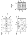
- Figure 2 is a simplified drawing of a metering device;
- Figure 3 is a plan view of two metering devices with components shown in phantom lines;
- Figure 4 is cross-section taken along line A-A in Figure 2; and
- Figure 5 is a simplified drawing of a prior art hydraulic system.
- Referring to Figure 1, a
hydraulic system 8 is shown which comprises: apump 10 which forms a source of hydraulic fluid; a plurality of hydraulic devices which in the example shown arehydraulic rams metering mechanism 15 comprising a plurality ofmetering devices metering devices connection 20 so that the flow of fluid or pressure at theoutlets 22 thereof are substantially equal regardless of the resistance to flow downstream of each metering device. Theconnection 20 can take any suitable form, such as an electronic, hydraulic or mechanical linkage, and details ofconnection 20 will be described in greater detail hereinafter. When the hydraulic system is in use,pump 10 can typically supply fluid over a range of pressures sufficient to overcome the internal resistance of the hydraulic system and drive the rams as required. Such pressure is supplied to theinlets 24 of themetering devices pistons 26 of the rams are controlled to extend and retract by an equal distance, regardless of the load on each piston. - The
metering devices single inlet 25 in fluid communication withpressure source 10.Fluid entering inlet 25 is directed along internal ducts to inlet 24 of respective metering devices. Alternatively, a common housing may have inlets for each metering device. - Although the hydraulic system shown comprises two
rams metering devices - Each metering device when taken in isolation allows fluid to flow only when a pressure gradient exists between inlet and outlet thereof. Increase and decrease in flow is dependent on the pressure gradient. Therefore, for a predetermined inlet pressure, flow decreases if the outlet pressure increases. Outlet pressure increases if the load on the associated hydraulic device increases. In a system of parallel rams as shown in Figure 1, the load on
rams metering devices Connection 20 allows the transmission of hydraulic force between metering devices. - Looking at an example in which the load on
ram 14 is greater than the load onram 12, the pressure gradient acrossmetering device 18 will be relatively smaller and the pressure gradient acrossmetering device 16 will be relatively larger. Therefore,connection 20 allows the transmission of the forces betweenmetering devices pistons 26 extend by an equal distance. - There now follows a more detailed description of
metering devices connection 20 with reference to Figures 2 to 4. - Referring to Figure 2,
metering device 16 ofmetering mechanism 15 comprisesfirst spur gear 28 andsecond spur gear 30 which intermesh and have axes of rotation X and Y, respectively. It should be noted that reference is made herein to a first gear and a second gear for convenience of description, but either gear may be considered the first gear or the second gear. - A
housing 32 definespumping chamber 34 in whichgears pump 10 causes a pressure gradient acrossdevice 16 betweeninlet 24 andoutlet 22, which causes the gears to rotate and fluid to flow from the inlet to the outlet.First gear 28 rotates about axis X in a first direction andsecond gear 30 rotates about axis Y in a second, or opposing, direction. The close tolerances between the intermeshing gear teeth of both gears and between the teeth and the chamber wall ensure that substantially no fluid flow occurs without rotation of the gears. - Figure 3 shows
metering devices common housing 32 ofmetering mechanism 15. Both devices are provided in a common housing for space efficiency, but equally, separate housings could be provided.Metering device 18 has the same function asmetering device 16 described above, and comprisesfirst spur gear 36 andsecond spur gear 38 which intermesh and have axes of rotation X and Y, respectively.First gear 36 rotates about axis X in the same direction asfirst gear 28, andsecond gear 38 rotates in the same direction assecond gear 30. -
Housing 32 defines afurther pumping chamber 40 in whichgears first gears common shaft 42 supported bythrust bearings 46 for rotation about axis X, and thesecond gears common shaft 44 supported by thrust bearings for rotation about axis Y. - As shown in Figure 4,
second gears first gears - When the
metering mechanism 15 is in use,pump 10 provides a source of hydraulic pressure and is in fluid communication with the inlets of the metering mechanism. When the load onrams metering devices gears shaft 44 is equal in magnitude and direction. When the load is larger on, for example,ram 12, there is a larger pressure gradient acrossmetering device 18 than acrossmetering device 16. Therefore, the turning moment applied toshaft 44 bygear 38 is larger than that applied bygear 30. Since the angular velocity ofshaft 44 is determined by bothgears gear 38 increases the angular velocity ofgear 30, andgear 30 retards the angular velocity ofgear 38. Accordingly, flow atoutlets 22 is equal and therefore extension ofpistons 26 is equal. -
Connection 20 may take the form of arigid shaft 44 as shown in Figures 2 to 4, but equally may take any suitable form provided that the connection restricts relative rotation between the appropriate gears. - After prolonged use, fluid may leak around the gears of the
metering devices outlet 22 to theinlet 24 thereof thereby bypassing the gear mechanism such that the duct can be opened in order to re-set the system to a starting condition. The by-pass ducts may be formed integrally with the housing of each metering device or with the common housing of the metering devices, or alternatively may be formed by means exterior to such a housing.
Claims (9)
- A metering mechanism comprising a plurality of metering devices for metering the supply of fluid from a source of hydraulic pressure to outlets thereof in fluid communication with respective hydraulic devices, wherein each metering device comprises a first gear rotatable in a first direction and a second gear rotatable in a second direction, said gears intermeshing with each other and being rotatable in response to the supply of hydraulic pressure from said source for metering flow of fluid from said source to said outlet thereof, wherein the first gears of said metering devices are connected such that relative rotation between said first gears is restricted so that respective said outputs receive substantially an equal flow of fluid when said source provides hydraulic pressure.
- A mechanism as claimed in claim 1, comprising mechanical linkage means for connecting the first gears of said metering devices so that relative rotation between the first gears is restricted.
- A mechanism as claimed in claim 2, wherein said linkage means comprises a shaft common to said first gears and rotatable by said first gears.
- A mechanism as claimed in claim 2 or 3, wherein said metering devices and said linkage means are housed in a common housing.
- A mechanism as claimed in claim 4, wherein said common housing comprises an inlet for receiving the supply of hydraulic pressure from said source, said inlet being common to each of said metering devices.
- A mechanism as claimed in any one of the preceding claims, wherein each metering device comprises a bypass duct between said inlet and said outlet thereof for equalising the hydraulic pressure therebetween.
- A hydraulic system comprising: a mechanism as claimed in any one of claims 1 to 6, a plurality of hydraulic devices in fluid communication with respective said outlets of the metering devices; and at least one source of hydraulic fluid wherein, in use, said at least one source of hydraulic pressure supplies pressurised fluid to the metering devices and said metering devices control the flow of fluid so that said hydraulic devices receive an equal flow of fluid.
- A system as claimed in claim 7, comprising a single source of hydraulic pressure common in fluid communication with the inlets of said metering devices.
- A system as claimed in claim 7 or claim 8, wherein the hydraulic devices are hydraulic rams.
Priority Applications (1)
| Application Number | Priority Date | Filing Date | Title |
|---|---|---|---|
| EP05270082A EP1788256A1 (en) | 2005-11-21 | 2005-11-21 | A metering mechanism |
Applications Claiming Priority (1)
| Application Number | Priority Date | Filing Date | Title |
|---|---|---|---|
| EP05270082A EP1788256A1 (en) | 2005-11-21 | 2005-11-21 | A metering mechanism |
Publications (1)
| Publication Number | Publication Date |
|---|---|
| EP1788256A1 true EP1788256A1 (en) | 2007-05-23 |
Family
ID=35976564
Family Applications (1)
| Application Number | Title | Priority Date | Filing Date |
|---|---|---|---|
| EP05270082A Withdrawn EP1788256A1 (en) | 2005-11-21 | 2005-11-21 | A metering mechanism |
Country Status (1)
| Country | Link |
|---|---|
| EP (1) | EP1788256A1 (en) |
Cited By (2)
| Publication number | Priority date | Publication date | Assignee | Title |
|---|---|---|---|---|
| CN107605842A (en) * | 2017-10-11 | 2018-01-19 | 长治市潞安合力机械有限责任公司 | A kind of gear-type hydraulic synchronizer |
| CN111550472A (en) * | 2019-12-30 | 2020-08-18 | 福建工程学院 | A Distributed Pump Controlled Adjacent Deviation Coupled Neural Network PID Hydraulic Climbing Formwork Jacking System |
Citations (5)
| Publication number | Priority date | Publication date | Assignee | Title |
|---|---|---|---|---|
| US2291578A (en) * | 1939-05-13 | 1942-07-28 | Pump Engineering Service Corp | Hydraulic equalizer |
| GB1157170A (en) * | 1966-08-10 | 1969-07-02 | Commercial Shearing | Hydraulic Circuit |
| US3495610A (en) * | 1967-08-04 | 1970-02-17 | Harry W Van Aken Jr | Flow divider |
| US4324411A (en) * | 1980-06-05 | 1982-04-13 | International Harvester Company | Implement level lift system |
| US4335894A (en) * | 1980-06-05 | 1982-06-22 | International Harvester Co. | Implement level lift system with rephasing valves |
-
2005
- 2005-11-21 EP EP05270082A patent/EP1788256A1/en not_active Withdrawn
Patent Citations (5)
| Publication number | Priority date | Publication date | Assignee | Title |
|---|---|---|---|---|
| US2291578A (en) * | 1939-05-13 | 1942-07-28 | Pump Engineering Service Corp | Hydraulic equalizer |
| GB1157170A (en) * | 1966-08-10 | 1969-07-02 | Commercial Shearing | Hydraulic Circuit |
| US3495610A (en) * | 1967-08-04 | 1970-02-17 | Harry W Van Aken Jr | Flow divider |
| US4324411A (en) * | 1980-06-05 | 1982-04-13 | International Harvester Company | Implement level lift system |
| US4335894A (en) * | 1980-06-05 | 1982-06-22 | International Harvester Co. | Implement level lift system with rephasing valves |
Cited By (3)
| Publication number | Priority date | Publication date | Assignee | Title |
|---|---|---|---|---|
| CN107605842A (en) * | 2017-10-11 | 2018-01-19 | 长治市潞安合力机械有限责任公司 | A kind of gear-type hydraulic synchronizer |
| CN111550472A (en) * | 2019-12-30 | 2020-08-18 | 福建工程学院 | A Distributed Pump Controlled Adjacent Deviation Coupled Neural Network PID Hydraulic Climbing Formwork Jacking System |
| CN111550472B (en) * | 2019-12-30 | 2022-04-12 | 福建工程学院 | Distributed pump-controlled adjacent deviation coupling neural network PID hydraulic climbing formwork jacking system |
Similar Documents
| Publication | Publication Date | Title |
|---|---|---|
| US11408442B2 (en) | System to pump fluid and control thereof | |
| CN103097242B (en) | Be particularly useful for propelling and the Movement transmit assembly of autogiro | |
| EP3344853B1 (en) | System to pump fluid and control thereof | |
| EP3507156B1 (en) | Dual input pump and system | |
| KR101664646B1 (en) | Gear pump or hydraulic gear motor with helical toothing provided with hydraulic system for axial thrust balance | |
| US7849686B2 (en) | Valve assembly and a hydraulic actuator comprising the valve assembly | |
| MX2008011588A (en) | Pump assembly. | |
| US8863510B2 (en) | Electrohydraulic actuator with a pump incorporated in the piston | |
| US5241826A (en) | Fixed geometry variable displacement pump system | |
| EP3344874A1 (en) | System to pump fluid and control thereof | |
| CN110307199B (en) | Hydraulic control system | |
| US7788988B2 (en) | Drive assemblies | |
| US9056672B2 (en) | Hydraulically regulated electromagnetic actuator, and landing gear fitted with such an actuator for controlling same | |
| EP2042737B1 (en) | Pressure recovery system | |
| AU2019240710B2 (en) | System to pump fluid and control thereof | |
| US7677035B2 (en) | Control system for a hydraulic servomotor | |
| CN104981607B (en) | Hydraulic gear motors, gear pumps and transmissions with infinitely variable parameters | |
| CN109027395A (en) | The control system and adjustment type actuator of electro-hydraulic linkage | |
| CN117401593A (en) | Driving control system applied to hydraulic winch | |
| HK1208717B (en) | Gear pump or hydraulic gear motor with helical toothing provided with hydraulic system for axial thrust balance |
Legal Events
| Date | Code | Title | Description |
|---|---|---|---|
| PUAI | Public reference made under article 153(3) epc to a published international application that has entered the european phase |
Free format text: ORIGINAL CODE: 0009012 |
|
| AK | Designated contracting states |
Kind code of ref document: A1 Designated state(s): AT BE BG CH CY CZ DE DK EE ES FI FR GB GR HU IE IS IT LI LT LU LV MC NL PL PT RO SE SI SK TR |
|
| AX | Request for extension of the european patent |
Extension state: AL BA HR MK YU |
|
| AKX | Designation fees paid | ||
| REG | Reference to a national code |
Ref country code: DE Ref legal event code: 8566 |
|
| STAA | Information on the status of an ep patent application or granted ep patent |
Free format text: STATUS: THE APPLICATION IS DEEMED TO BE WITHDRAWN |
|
| 18D | Application deemed to be withdrawn |
Effective date: 20071124 |