EP1787864A1 - Vehicle rear structure - Google Patents
Vehicle rear structure Download PDFInfo
- Publication number
- EP1787864A1 EP1787864A1 EP06024151A EP06024151A EP1787864A1 EP 1787864 A1 EP1787864 A1 EP 1787864A1 EP 06024151 A EP06024151 A EP 06024151A EP 06024151 A EP06024151 A EP 06024151A EP 1787864 A1 EP1787864 A1 EP 1787864A1
- Authority
- EP
- European Patent Office
- Prior art keywords
- vehicle
- guide rail
- view
- pull bar
- tailgate
- Prior art date
- Legal status (The legal status is an assumption and is not a legal conclusion. Google has not performed a legal analysis and makes no representation as to the accuracy of the status listed.)
- Granted
Links
- 230000008878 coupling Effects 0.000 claims description 97
- 238000010168 coupling process Methods 0.000 claims description 97
- 238000005859 coupling reaction Methods 0.000 claims description 97
- 238000003860 storage Methods 0.000 claims description 9
- 238000006073 displacement reaction Methods 0.000 claims description 7
- 238000012546 transfer Methods 0.000 claims description 5
- 230000007423 decrease Effects 0.000 abstract description 12
- 230000006866 deterioration Effects 0.000 abstract description 10
- 230000008901 benefit Effects 0.000 description 18
- 230000007246 mechanism Effects 0.000 description 14
- 230000002452 interceptive effect Effects 0.000 description 12
- 230000004044 response Effects 0.000 description 6
- 230000000007 visual effect Effects 0.000 description 4
- 230000008859 change Effects 0.000 description 3
- 230000003068 static effect Effects 0.000 description 3
- 238000007796 conventional method Methods 0.000 description 2
- 238000010586 diagram Methods 0.000 description 2
- 238000004519 manufacturing process Methods 0.000 description 2
- 238000012986 modification Methods 0.000 description 2
- 230000004048 modification Effects 0.000 description 2
- 230000003014 reinforcing effect Effects 0.000 description 2
- 238000007665 sagging Methods 0.000 description 2
- 229920003002 synthetic resin Polymers 0.000 description 2
- 239000000057 synthetic resin Substances 0.000 description 2
- 238000005452 bending Methods 0.000 description 1
- 244000309464 bull Species 0.000 description 1
- 239000000919 ceramic Substances 0.000 description 1
- 239000000463 material Substances 0.000 description 1
- 238000000034 method Methods 0.000 description 1
- 239000003973 paint Substances 0.000 description 1
- 230000008569 process Effects 0.000 description 1
- 238000007789 sealing Methods 0.000 description 1
- 238000012360 testing method Methods 0.000 description 1
- 238000003466 welding Methods 0.000 description 1
Images




Classifications
-
- B—PERFORMING OPERATIONS; TRANSPORTING
- B60—VEHICLES IN GENERAL
- B60R—VEHICLES, VEHICLE FITTINGS, OR VEHICLE PARTS, NOT OTHERWISE PROVIDED FOR
- B60R5/00—Compartments within vehicle body primarily intended or sufficiently spacious for trunks, suit-cases, or the like
- B60R5/04—Compartments within vehicle body primarily intended or sufficiently spacious for trunks, suit-cases, or the like arranged at rear of vehicle
- B60R5/044—Compartments within vehicle body primarily intended or sufficiently spacious for trunks, suit-cases, or the like arranged at rear of vehicle luggage covering means, e.g. parcel shelves
- B60R5/045—Compartments within vehicle body primarily intended or sufficiently spacious for trunks, suit-cases, or the like arranged at rear of vehicle luggage covering means, e.g. parcel shelves collapsible or transformable
- B60R5/047—Compartments within vehicle body primarily intended or sufficiently spacious for trunks, suit-cases, or the like arranged at rear of vehicle luggage covering means, e.g. parcel shelves collapsible or transformable collapsible by rolling-up
Definitions
- the present invention relates to a vehicle rear structure equipped with a tonneau cover adapted to be disposed to cover an upper side of a rear cargo compartment, and designed to allow an rear end of the tonneau cover to be moved upwardly and downwardly.
- a vehicle rear structure which comprises a tailgate swingably supported about a horizontal shaft pivotally attacked to a vehicle body, and adapted to cover a rear opening of the vehicle body, a tonneau cover (roll blind) for covering a top plane of a rear cargo compartment, a pair of guide rails mounted to the vehicle body along opposite lateral edges of the rear opening, and a pair of sliders (guide slides) detachably engaged with a pull bar provided at a rear end of the tonneau cover, wherein the slider is adapted to be slidingly displaced along the guide rail during a manual operation of opening and closing the tailgate, so as to allow the bull bar to be moved between a lower position where the tonneau cover is closed (tonneau-cover close position) and an upper position where the tonneau cover is opened (tonneau-cover open position), as disclosed in US 6402217 B1 (equivalent to Japanese Patent No. 3613581 ).
- the guide rails are positioned along the respective opposite right and left edges of the rear opening which are inclined in upwardly tapering relation to each other, when viewed from a rear end of the vehicle, i.e., in a rear view of the vehicle. That is, a distance between the right and left guide rails changes between when the pull bar is at the tonneau-cover open position where the pull bar has been moved to a relatively upper position through the tailgate opening operation and when the pull bar is at the tonneau-cover close position where the pull bar has been moved to a relatively lower position through the tailgate closing operation.
- the pull bar is provided with a pair of protrudable pins adapted to protrude laterally in a variable manner, at respective opposite right and left ends thereof.
- the protrudable pins are designed such that a protruding amount thereof is changed correspondingly to the upward/downward displacement of the pull bar so as to allow the right and left ends of the pull bar to be constantly supported by the guide rails through the protrudable pins and the sliders.
- this tonneau cover apparatus has problems about structural complexity, and wobbling in the right and left ends of the pull bar during the upward/downward displacement thereof.
- the right and left guide rails are positioned parallel to each other in the rear view of the vehicle to allow the right and left ends of the pull bar to be constantly supported by the guide rails without providing the protrudable pins at the right and left ends of the pull bar.
- the right and left guide rails are arranged to extend downwardly and parallel to each other from a position along the rear opening, each lower end of the guide rails will be located at a position protruding inwardly from the rear opening to cause a problem of hindering an operation of putting/taking articles in/out of a rear cargo compartment.
- the reduced distance between the right and left guide rails leads to disadvantages of deterioration in rearward visibility and decrease in width dimension of a tonneau cover to be arranged between the guide rails.
- the present invention provides a vehicle rear structure which comprises a tailgate adapted to openably cover a rear opening defined between a pair of right and left rear pillars formed in a rear of a vehicle body, a tonneau cover adapted to be disposed to cover an upper side of a rear cargo compartment located in front of the rear opening, a pull bar provided at a rear end of the tonneau cover, and a pair of right and left guide rails slidably supporting respective opposite right and left ends of the pull bar.
- the pull bar is adapted to be slidingly displaced along the guide rails so as to allow the rear end of the tonneau cover to be moved upwardly and downwardly.
- the vehicle rear structure is characterized in that the right and left guide rails are positioned parallel to each other, when viewed from a rear end of the vehicle, i.e., in a rear view of the vehicle.
- Each of the guide rails has an upper portion located at a position overlapping a corresponding one of the rear pillars in the rear view of the vehicle, and in front of the rear pillar, when viewed from a lateral side surface of the vehicle, i.e., in a side view of the vehicle.
- each of the guide rails has a lower portion located at a position overlapping the rear pillar in the side view of the vehicle.
- the right and left guide rails are positioned parallel to each other in a rear view of the vehicle, and the upper portion of the guide rail is located at a position overlapping the rear pillar in the rear view of the vehicle and in front of the rear pillar in a side view of the vehicle. Further, the lower portion of the guide rail is located at a position overlapping the rear pillar in the side view of the vehicle, and on the inside of said rear pillar in the rear view of the vehicle.
- the rear end of the tonneau cover can be displaced upwardly and downwardly along the guide rails in a simplified structure without disadvantages, such as deterioration in rearward visibility, due to decrease in distance between the right and left guide rails.
- FIGS. 1 to 3 shows a vehicle rear structure according to a first embodiment of the present invention.
- This vehicle rear structure comprises a tailgate 3 adapted to be swingingly displaced about an upper hinge 1 provided in a rear of a vehicle body so as to openably cover a rear opening 2, a tonneau cover 6 adapted to be disposed to cover an upper side of a rear cargo compartment 5 defined in front of the rear opening 2 and in the rear of a seat back 4 of a passenger seat (rear seat), a pull bar 6 provided at a rear end of the tonneau cover 6, and a pair of right and left guide rails 8 slidably supporting respective opposite right and left ends of the pull bar 7.
- the reference numeral 9 indicates amounting line of a sealing member to be mounted along a periphery of the rear opening 2.
- the tonneau cover 6 comprises a sheet-like member associated with a retracting case 10 positioned along an upper region of a rear surface of the seat back 4, and a pull bar 7 supported by the guide rail 8, so as to extend between the pull bar 7 and the retracting case 10.
- the retractor case 10 houses a retracting mechanism which applies a biasing force to the tonneau cover 6 in a retracting direction. Specifically, a given tension corresponding to the biasing force of the retracting mechanism is constantly given to the tonneau cover 6, and the tonneau cover 6 is extracted from the retractor case 10 according to an after-mentioned opening/closing operation of the tonneau cover 6. As shown in FIG.
- a cover plate 11 composed of a synthetic resin plate is integrally formed with the pull bar 7 to protrude from a rear surface of the pull bar 7 so as to cover an upper side of a rear space of the rear cargo compartment 5.
- a rear end of the tonneau cover 6 is fixed to the pull bar 7 through engagement means (not shown) or the like.
- the pull bar 7 has laterally opposite ends each held by a slider 12 adapted to be slidingly displaced along the guide rail 8.
- the slider 12 is adapted to be moved upwardly and downwardly by up-down drive means 13.
- the up-down drive means 13 comprises: a drive cable 14 extending along the guide rail 8 and having the slider 12 fixed thereto at a given position; a drive roller 15 and a driven roller 16 which are positioned at respective opposite upper and lower ends of the guide rail 8 and wound by the drive cable 14; and a drive motor 17 adapted to rotationally drive the drive roller 15.
- the drive roller 15 is rotated according to a driving force of the drive motor 17, and thereby the slider 12 is displaced together with the drive cable 14 to move the pull bar 7 and the rear end of the tonneau cover 6.
- each of the right and left guide rails 8 is positioned in a downwardly-inclined posture relative to a rearward direction, when viewed from a lateral side surface of the vehicle, i.e., in a side view of the vehicle.
- the guide rails 8 are positioned parallel to each other along a vertical direction, when viewed from a rear end of the vehicle, i.e., in a rear view of the vehicle.
- each of the guide rails 8 has an upper portion which is located at a position overlapping a body (an inward sidewall surface of an inner pillar) of a corresponding one of a pair of right and left rear pillars 18 formed in the rear of the vehicle, in the rear view of the vehicle ,and in front of the rear pillar 18 in the side view of the vehicle (specifically, at a position overlapping a rear edge portion of a quarter window 19 positioned in front of the rear pillar 18 in the side view of the vehicle, and a position adjacent to an inward surface of the quarter window in the rear of the vehicle, as shown in FIG. 1).
- the upper portion of the guide rail 18 is located most adjacent to the quarter window 19 in the rear view of the vehicle. Further, the upper portion of the guide rail 18 is located along an opaque light-shielding region 20 formed in a periphery of the quarter window 19 through an application of black ceramic paint or the like, and a portion of the rear pillar 18 on the side of the quarter window 19, i.e., a flange 21 of the rear pillar 18 located at a front edge thereof, as shown in FIG. 5.
- the rear pillar 18 includes an outer panel 18a and an inner panel 18b which are formed with flanges 20a, 20b, 21a, 21b.
- the flanges 20a, 20b and the flanges 21b, 21b are joined together by welding or the like to define a closed section extending vertically in a downwardly-inclined posture relative to the rearward direction in the rear of the vehicle body.
- the guide rail 8 is positioned in a downwardly-inclined posture relative to the rearward direction with an inclination angle closer to a horizontal direction than that of the rear pillar 18.
- the guide rail 8 has a lower portion which is located at a position overlapping the body of the rear pillar 18 in the side view of the vehicle and on the inside of the rear pillar 18 in the rear view of the vehicle.
- the guide rail 8 is positioned in a downwardly-inclined posture relative to the rearward direction with an inclination angle closer to a horizontal direction than that of the rear pillar 18.
- the lower portion of the guide rail 8 is located opposed to the body of the rear pillar 18, i.e., a portion of the inner pillar (inner panel) except for the flange 21, in a width or lateral direction of the vehicle, and frontwardly relative to a rear edge of the rear pillar 18. That is, the lower portion of the guide rail 8 is located at a position overlapping the rear pillar 18 in the side view of the vehicle.
- the guide rail 8 includes a front plate 22 supporting a front surface of the slider 12, a side plate supporting an outward surface of the slider 12, and a guide groove portion 24 continuously extending between the front plate 22 and the side plate 23. Further, a driven portion 25 of the slider 12 to be driven by the drive cable 14 is disposed inside the guide groove portion 24. As shown in FIGS. 5 and 7, the upper and lower portions of the guide rail 8 are mounted to the inward side surface of the rear pillar 18 through mounting brackets 26, 27, respectively.
- a trim member 28 is disposed on the side of an interior space of the vehicle relative to the rear pillar 18 to cover the inward side surface of the rear pillar 18 (see FIG. 8). As shown in F1GS. 5 and 7, this trim member 28 includes a sidewall plate 29 disposed opposed to the inward sidewall surface of the rear pillar 18, and a front wall plate 30 extending continuously from a front edge of the sidewall plate 29.
- the sidewall plate 30 of the trim member 28 is disposed in spaced-apart relation to the inner panel 18b of the rear pillar 18 with a given distance therebetween, in such a manner as to extend rearwardly from a front edge thereof in a given inclination direction to have a rear edge located inwardly relative to the front edge, in a horizontal cross-sectional view thereof.
- the front wall plate 30 is disposed to extend rearwardly in an inclination direction opposite to that of the sidewall plate 29 (i.e., in such a manner as to allow an outward edge thereof to be located on the side of the rear end of the vehicle) to have a rear edge oriented toward a rear edge portion of the quarter window 19.
- the sidewall plate 29 and the front wall plate 30 form a V-shaped protrusion 31 protruding frontwardly in a top plan view of the vehicle, at a front edge of the trim member 28.
- the sidewall plate 29 of the trim member 28 disposed in spaced-apart relation to the inward sidewall surface of the rear pillar 18 defines a storage space 32 for storing the guide rail 8 and other component, in cooperation with the rear pillar 18.
- an open switch (not shown) is turned on to rotate the drive motor 17 in a normal direction so as to drive the drive roller 15 and the drive cable 14.
- the slider 12 fixed to each of the lateral ends of the pull bar 7 is moved upward from a lower position, i.e., a tonneau-cover close position, to an upper position, i.e., a tonneau-cover open position, along the guide rail 8.
- the rear end of the tonneau cover 6 is moved to the upper open position to facilitate an operation of putting/taking articles in/out of the rear cargo compartment 5 (see the tow-dot chain line in FIG. 1).
- a close switch (not shown) is turned on to rotate the drive motor 17 in a reverse direction so as to drive the drive roller 15 and the drive cable 14.
- the slider 12 fixed to each of the lateral ends of the pull bar 7 is moved downward from to the upper position, i.e., the tonneau-cover open position to the lower position, i.e., the tonneau-cover close position, along the guide rail 8.
- the rear end of the tonneau cover 6 is moved to the lower close position to cover articles in the rear cargo compartment 5 (see the solid line in FIG 1).
- the vehicle rear structure comprises the tailgate 3 adapted to openably cover the rear opening 2 defined between the pair of right and left rear pillars 18 formed in the rear of the vehicle body, the tonneau cover 6 adapted to be disposed to cover an upper side of the rear cargo compartment 5 located in front of the rear opening 2, the pull bar 7 provided at the rear end of the tonneau cover 6, and the pair of right and left guide rails 8 slidably supporting the respective opposite right and left ends of the pull bar 7, wherein the pull bar 7 is adapted to be slidingly displaced along the guide rails 8 so as to allow the rear end of the tonneau cover 6 to be moved upwardly and downwardly, the right and left guide rails 8 are positioned parallel to each other in the rear view of the vehicle, and the upper portion of each of the guide rails 8 is located at a position overlapping a corresponding one of the rear pillars 18 in the rear view of the vehicle and in front of the rear pillar 18 in the side view of the vehicle.
- the lower portion of the guide rail 8 is located at a position overlapping the rear pillar 18 in the side view of the vehicle and on the inside of said rear pillar 18 in the rear view of the vehicle.
- the rear end of the tonneau cover 6 can be displaced upwardly and downwardly along the guide rails 8 in a simplified structure without disadvantages, such as deterioration in rearward visibility, due to decrease in distance between the right and left guide rails 8.
- the rear pillar 18 positioned in the side (lateral) edge of the rear opening 2 is inclined such that the upward end is located inwardly in the rear view of the vehicle.
- the right and left guide rails 8a as indicated by the broken line in FIG. 2 are positioned parallel to each other and located inwardly relative to the rear pillar 18 in the entire length thereof, lower ends of the guide rails 8a will inevitably protrude inwardly toward the rear opening 2.
- the guide rails 8 can be positioned parallel to each other while preventing interference with the rear pillar 18 having inwardly-inclined upper end, and sufficiently assuring the distance therebetween.
- the pull bar 7 can be slidingly displaced smoothly along the guide rails 8 while constantly supporting the right and left ends of the pull bar 7 by the guide rails 8 without employing a complicated mechanism, such as the protrudable pins 8 capable of protruding in a variable manner as disclosed in the aforementioned conventional technique.
- the above vehicle rear structure can prevent deterioration in rearward visibility and in user-friendliness during an operation of putting and taking articles in/out of the rear cargo compartment 5, due to obstruction/hindrance of the guide rails 8 and sufficiently ensure a width dimension of the tonneau cover 6 to be disposed between the guide rails 8.
- the lower portion of the rear pillar 18 is located outwardly relative to the upper portion thereof.
- the lower portion of the guide rail 8 can be located at a position overlapping the rear pillar 18 in the side view of the vehicle, and on the inside of said rear pillar 18 in the rear view of the vehicle.
- the pull bar 7 can be moved to a rearward position by slidingly displacing the pull bar 7 along the guide rails 8 to the tonneau-cover close position, so as to provide an advantage of being able to effectively cover articles in the rear cargo compartment 5 by the tonneau cover 6.
- the upper portion of the guide rail 8 is located at a position overlapping the quarter window 19 in the side view of the vehicle, and at a position adjacent to an inward surface of the quarter window 19 in the rear view of the vehicle.
- This vehicle rear structure has an advantage that the distance of the right and left guide rails 8 can be further increased while preventing the upper portion of the guide rail 8 from interfering with the rear pillar 18.
- the light-shielding region 20 can advantageously prevent the guide rail 8 from becoming visible from outside through the quarter window 19 even if the upper portion of the guide rail 8 is located adjacent to the inward surface of the quarter window 19 in the side view of the vehicle.
- an aesthetic appearance of the vehicle can be adequately maintained.
- the guide rail 18 is positioned such that the upper portion thereof is located most adjacent to the quarter window 19.
- this vehicle rear structure can prevent the guide rail 8 from interfering with the rear pillar 18, and can maximize the distance between the right and left guide rails 8 while allowing the guide rails 8 to be positioned parallel to each other.
- this vehicle rear structure has advantages of being able to ensure the distance between the right and left guide rails 8 while preventing the guide rail 8 from interfering with the rear pillar 18, and to effectively prevent the guide rail 8 from becoming visible from outside through the quarter window 19.
- the trim member in the vehicle rear structure including the outer panel 18a and the outer panel 18b which have flanges 20a, 20b, 21a, 21b joined together to form the rear pillar 18 in such a manner as to extend vertically in the rear of the vehicle body, the quarter window 19 positioned in front of the rear pillar 18, and the trim member covering the inward sidewall surface of the rear pillar 18, the trim member has the sidewall plate 29 extending rearwardly from a front edge thereof in a given inclination direction to have a rear edge located inwardly relative to the front edge, in a horizontal cross-sectional view thereof, and the front wall plate 30 extending continuously and rearwardly from the front edge of the sidewall plate in an inclination direction opposite to that of the sidewall plate 29 to have a rear edge oriented toward a rear edge portion of the quarter window 19.
- the inward sidewall surface of the rear pillar 18 can be advantageously covered by the trim member 28 without deterioration in rearward visibility.
- an outwardly-oriented visual line of a passenger seated in a passenger seat disposed in front of the rear pillar 18 is oriented rearwardly, i.e., a visual line J of the passenger viewing the outside through the quarter window 19 positioned in front of the rear pillar 18, is directed in a rearward and outward direction which is aliened with the inclination direction of the front wall plate 30.
- the above vehicle rear structure has an advantage of being able to effectively prevent the visual line J of the passenger from being blocked due to the presence of the front wall plate 30 so as to adequately ensure visibility through the quarter window 19.
- the chevron-shaped protrusion 31 composed of the sidewall plate 29 and the front wall plate 30 of the trim member 28 is formed at the front edge of the trim member 28 in the top plan view of the vehicle, and the sidewall plate 29 of the trim member 28 is disposed in spaced-apart relation to the inward wall surface of the rear pillar 18 to define the given storage space 32 between the trim member 28 and the rear pillar 18.
- the above vehicle rear structure has advantages of being able to define a relatively large storage space 32 between the trim member 32 and the rear pillar 18 while preventing the visual line J of the passenger due to the presence of the trim member 28, and store the guide rail 8, wire harnesses and other component using the storage space.
- a screw-type feed control mechanism adapted to screw-feed the slider 12, or up-down means having a drive cylinder adapted to push and pull the slider 12, may be used for displacing the pull bar 7 upwardly and downwardly along the guide rails based on the opening/closing operation of the tailgate 3.
- the slider 12 may be slidingly displaced by a passenger's manual operation after the opening/closing operation of the tailgate 3 to displace the pull bar 7 upwardly and downwardly.
- the first embodiment has been described based on one example where a given retracting tension is given to the tonneau cover 6 using a retracting mechanism housed in the retractor case positioned along the upper portion of the rear surface of the seat back 4 so as to prevent the tonneau cover 6 from sagging when the pull bar 7 is slidingly displaced along the guide rails based on the opening/closing operation of the tailgate 3.
- the tonneau cover 6 may be made of a stretchable material to prevent the sagging of the tonneau cover 6 in response to the upward/downward movement without providing the above retracting mechanism.
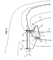
- FIGS. 9 to 11 show a tonneau-cover opening/closing mechanism according to a second embodiment of the present invention.
- This embodiment is generally different from the first embodiment in the following points.
- the opposite right and left ends of the pull bar 7 provided at the rear end of the tonneau cover 6 are coupled to the tailgate 3 so that a drive force based on the opening/closing operation of the tailgate 3 is transferred to the pull bar 7 to slidingly displace the pull bar 7 along a guide rail 38.
- the tonneau-cover opening/closing mechanism includes a coupling link 33 adapted to move the rear end of the tonneau cover 6 in conjunction with the above movement, and a reinforcing member 34 made of a synthetic resin and disposed on the side of a coupling portion between the tonneau cover 6 and the pull bar 7. A lateral portion of the rear end of the tonneau cover 6 and a lateral portion of the pull bar 7 are integrally clamped by the reinforcing member 34.
- each of the lateral ends of the pull bar 7 is provided with a connection bracket 35 for connecting the tonneau cover 6 to the coupling link 33.
- This connection bracket 35 includes a base plate 36 slidably supported along an inside surface of the guide rail 38.
- An engagement hole 37 for the coupling link 33 is formed in a rear portion of the base plate, and a U-shaped engagement portion 39 having a rear end with an opening is formed on an inward surface of the base plate 36 to protrude,inwardly from the inward surface.
- the lateral end of the pull bar 7 is disengageably engaged with the engagement portion 39, and this engaged state of the pull bar 7 is held by the biasing force of the retracting mechanism.
- the coupling link 33 includes an upper-end pivoted portion 40 extending horizontally, a downwardly-extending portion 41 extending obliquely rearwardly and downwardly from an inward end of the upper-end pivoted portion 40, a bent portion 42 extending obliquely frontwardly and downwardly from a lower end of the downwardly-extending portion 41, and a lower-end pivoted portion 43 extending horizontally and outwardly from a lower end of the bent portion 42.
- the coupling link 33 is prepared by subjecting a round bar to a bending process.
- the lower-end pivoted portion 43 of the coupling link 33 has an outward end inserted into the engagement hole 37 of the connection bracket 35 and a guide groove of the guide rail 38.
- a nut 45 is screwed on the inserted end to provide an engagement between the lower-end pivoted portion 43 and the guide rail 38.
- the upper-end pivoted portion 40 of the coupling link 33 has an outward end mounted to an inward surface of the tailgate 3 through a mounting bracket 46 to allow the pull bar 7 to be coupled to the tailgate 3.
- a protruding amount of the lower-end pivoted portion 43 is set at a value greater than that of the upper-end pivoted portion 40.
- each of the downwardly-extending portion 41 and the bent portion 42 is disposed in a inclined posture to extend downwardly and outwardly in the rear view of the vehicle.
- a rail-side pivoted point L2 i.e., a coupling point of the lower-end pivoted portion 43 to the connection bracket 35, is located outwardly relative to a tailgate-side pivoted point L1, i.e., a coupling point of the upper-end pivoted portion 40 to the tailgate 3.
- the downwardly-extending portion 41 of the coupling link 33 is located inwardly relative to the side (lateral) edge of the rear opening 2.
- An imaginary line L connecting the tailgate-side pivoted point L1 and the rail-side pivoted point L2 is inclined to be located laterally outwardly more and more toward a lower end. That is, the imaginary line L is located along the rear pillar 18 defining the side edge of the rear opening 2 inclined in an upwardly-tapering manner.
- the coupling link 33 is positioned such that the bent portion 42 thereof extends obliquely frontward relative to the downwardly-extending portion 41.
- the coupling link 33 has a vertically intermediate portion formed in an L shape protruding rearwardly.
- the downwardly-extending portion 41 and the bent portion 42 of the coupling link 33 is located inclinedly in a downwardly-tapering manner to allow the coupling link 33 to be disposed along the inward surface of the rear pillar 18 forming the side edge of the rear opening 2 when the tailgate 18 is closed.
- the guide rail 38 is formed of a plate member or the like having the guide groove 44 allowing the lower-end pivoted portion 43 of the coupling link 33 to slidingly move therealong. Further, the guide rail 38 is formed to have a vertically central portion curved to protrude frontwardly and downwardly, in the side view of the vehicle, and the right and left guide rails 38 are positioned parallel to each other along a vertical direction.
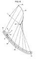
- the guide rail 38 is formed to have a pull-bar guide direction for guiding the pull-bar 7, which is arranged such that, during the closing operation of the tailgate 3, an angle between the pull-bar guide direction and an input direction of a closing operation-based driving force to be applied from the coupling link 33 and the connection bracket 35 thereto, is set at an obtuse angle.
- the closing operation-based driving force is input in a direction A along a line connecting the upper-end pivoted portion 40 and the lower-end pivoted portion 43 of the coupling link 33.
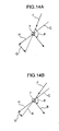
- the input direction A of the closing operation-based driving force and the guide direction B of the guide rail 38 is set to be located frontward relative to a line extending in a direction C orthogonal to the guide direction B of the guide rail 38 so as to allow an angle ⁇ between the input direction A of the closing operation-based driving force and the guide direction B of the guide rail 38 to be set at an obtuse angle.
- an arc-shaped line indicated by the reference code D is a locus of the upper-end pivoted portion 40 corresponding to the closing operation of the tailgate 3, and the reference code 1 is an upper hinge serving as a pivot of the tailgate 3.
- the angle ⁇ between the input direction A of the closing operation-based driving force and the guide direction B of the guide rail 38 is set at an obtuse angle.
- a moving force G will act to allow the lower-end pivoted portion 43 of the coupling link 33 and the pull bar 7 to be slidingly displaced along the guide rails 38.
- FIG. 14B in response to a decrease in the angle ⁇ , the moving force G decreases, and a component force H of the closing operation-based driving force F acting in a direction C orthogonal to the guide direction B increases.
- a frictional force expressed as a value calculated by multiplying the component force H by a friction coefficient ⁇ i.e., a frictional resistance caused when the lower-end pivoted portion 43 of the coupling link 33 is slidingly moved along the guide rails 38, is apt to increase.
- the angle ⁇ between the input direction A of the closing operation-based driving force and the guide direction B of the guide rail 38, at the upper end of the guide rail 38 is preferably set at a value greater than that the vertically intermediate portion and the lower portion of the guide rail 38, for example, at about 135°.
- the pull-bar guide direction B of the guide rail 38 is arranged such that the angle ⁇ is continuously (linearly) changed from 135° to 110°.
- the pull-bar guide direction B at the lower end of the guide rail 38 i.e., the pull-bar guide direction B in the final stage of the closing operation the tailgate 3, is set at an approximately horizontal direction, as shown in FIG. 13.
- the upper portion of the guide rail 38 is located in frontwardly spaced-apart relation to the rear opening 2 defined by the rear pillars 18 extending approximately linearly in a downwardly-inclined posture relative to the rearward direction, and the lower portion of the guide rail 38 is located closer to the rear opening 2.
- the tonncau-cover opening/closing mechanism includes the coupling link 33 coupling the pair of right and left guides rails slidably supporting the right and left ends of the pull bar 7 provided at the rear end of the tonneau cover 6, and the right and left ends of the pull bar 7, to the tailgate 3.
- the coupling link 33 is adapted to transfer a driving force F based on the opening/closing operation of the tailgate 3, to the pull bar 7 therethrough, so as to allow the rear end of the tonneau cover 6 to be moved upwardly and downwardly in conjunction with a sliding displacement of the pull bar 7 along the guide rail 38 according to the driving force F.
- the guide rail 38 is formed, in the side view of the vehicle, to include the vertically central portion curved to protrude frontwardly and downwardly, and have a pull-bar guide direction for guiding the pull-bar 7, which is arranged such that, during the closing operation of the tailgate 7, an angle between the pull-bar guide direction B of the guide rail 38 and the input direction A of the closing operation-based driving force F to be applied from the coupling link 33 to the pull bar 7, is set at an obtuse angle.
- the rear end of the tonneau cover 6 can be moved upwardly and downwardly in conjunction with the opening/closing operation of the tailgate 3 in a simplified structure to move the tonneau cover 6 between the lower close position and the upper open position.
- the pull bar 7 is adapted to be slidingly displaced along the guide rails 38 in conjunction with the opening/closing operation of the tailgate 3 to move the rear end of the tonneau cover 6 upwardly and downwardly.
- the rear end of the tonneau cover 6 can be moved upwardly and downwardly in conjunction with the opening/closing operation of the tailgate 3 without providing driving means separately to move the tonneau cover 6 between the lower close position and the upper open position.
- the rear end of the tonneau cover 6 can be moved to the upper open position to facilitate an operation of putting/taking articles in/out of the rear cargo compartment 5.
- the rear end of the tonneau cover 6 can be moved to the lower close position to cover articles in the rear cargo compartment 5.
- the right and left ends of the pull bar 7 can be constantly supported by the guide rails 38 without employing particular means, such as the protrudable pins capable of protruding in a variable manner as disclosed in the aforementioned conventional technique to provide a simplified structure.
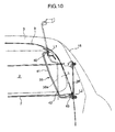
- the lower end of the guide rail 38 can be located outwardly relatively the rear opening 2 as indicated by the solid line in FIG. 11 while preventing the lower end of the guide rail 38a from being located inwardly relative to the rear opening 2, due to the right and left side edges of the rear opening inclined in an upward tapering manner in the rear view of the vehicle, as indicated by the broken line in FIG. 10. This makes it possible to prevent the guide rails 38 from hindering the operation of putting/taking articles on/out of the rear cargo compartment 5 and sufficiently ensure the width dimension of the tonneau cover 6 to be disposed between the guide rails 38.
- the guide direction B of the guide rail 38 is arranged such that the angle ⁇ between the input direction A of the closing operation-based driving force F acting from the coupling link 33 to the pull bar 7 and the guide direction B of the guide rail 38, during the closing operation the tailgate 3, is set at an obtuse angle.
- an inclination angle of the closing operation-based driving force to be input from the tailgate 3 in the open state into the pull bar 7 through the coupling link 33, with respect to a horizontal plane becomes smaller as the positing of the guide rail 38 is shifted toward an front end of the vehicle relative to the rear opening of the vehicle, and the input direction A of the closing operation-based driving force comes closer to a horizontal direction. Consequently, an effective force for the downward movement along the guide rail is apt to decrease.
- the guide rail 38 formed to include the vertically central portion curved to protrude frontwardly and downwardly, in the side view of the vehicle, and the guide direction B of the guide rail 38 is arranged such that the angle ⁇ between the input direction A of the closing operation-based driving force F acting from the coupling link 33 to the pull bar 7 and the guide direction B of the guide rail 38, during the closing operation the tailgate 3, is set at an obtuse angle.
- the angle ⁇ between the input direction A of the closing operation-based driving force and the guide direction B of the guide rail 38 is set at a larger value in an upper end of the guide rail 38 than in the vertically intermediate portion of the guide rail 38.
- the pull-bar guide direction B in the lower end of the guide rail 7 is set at an approximately horizontal direction.
- the angle ⁇ is continuously changed. This makes it possible to effectively prevent the occurrence of wobbling during a sliding movement of the pull bar 7 due to sudden change of the angle ⁇ at the portion, to allow the pull bar 7 to be slidingly displaced along the guide rails 38 smoothly.
- the guide rail 38 is positioned such that, in the side view of the vehicle, the upper portion of the guide rail 38 is located in frontwardly spaced-apart relation to the rear opening 2 extending approximately linearly in a downwardly-inclined posture relative to the rearward direction, and the lower portion of the guide rail 38 is located closer to the rear opening 2, so that, when the tailgate 3 is closed, the pull bar 7 and the rear end of the tonneau cover 6 are moved to a position adjacent to the side edges of the rear opening 2 while positioning the right and left guide rails 38 parallel to each other and sufficiently ensuring the distance between the guide rails 38.
- the above upper portion of the guide rail 38 located in frontwardly spaced-apart relation to the rear opening 2 makes it possible to prevent the upper portion of the coupling link 33 being moving upwardly along the guide rail 38 during the opening operation of the tailgate 3, from interfering with the side edge of the rear pillar 38.
- the right and left guide rails 38 can be positioned parallel to each other while sufficiently ensuring the distance between the guide rails without interference between the guide rails 38 and the rear pillars 18 in the rear view of the vehicle.
- the pull bar 7 and the rear end of the tonneau cover 6 are moved to a position adjacent to the side edges of the rear opening 2.
- approximately the entire area of the rear cargo compartment 5 including a rear region thereof can be advantageously covered by the tonneau cover 6 to provide a sufficient function of covering articles, to the tonneau cover.
- the rail-side pivoted point L2 of the coupling link 33 serving as a coupling point of the lower-end pivoted portion 43 to the guide rail 38 is set to be located outwardly relative to the tailgate-side pivoted point L1 of the coupling link 33 serving as a coupling point of the upper-end pivoted portion 40 to the tailgate 3, in the rear view of the vehicle.
- the guide rails 38 can be positioned laterally outward to sufficiently ensure the width dimension of the tonneau cover 6.
- the upper end of the guide rail 38 is designed to extend up to a position adjacent to an upper edge of the rear opening 2 to allow the rear end of the tonneau cover 6 to be largely moved upwardly during the opening operation of the tailgate 3, the upper portion of the coupling link 33 moved upward along the guide rail 34 during the opening operation of the tailgate 3 is likely to interfere with the side edge of the rear opening 2 inclined in an upwardly tapering manner in the rear view of the vehicle, Moreover, if the guide rail 38 connected with the lower-end pivoted portion 43 of the coupling link 33 is positioned inwardly, the distance between the right and left guide rails 38 will inevitably decrease and hinder the operation of putting/taking articles in/out of the rear cargo compartment (see the broken line in FIG 10).
- the rail-side pivoted point L2 of the coupling link 33 set to be located outwardly relative to the tailgate-side pivoted point L1 of the coupling link 33 as in the second embodiment provides advantages that even when the upper end of the guide rail 38 is designed to extend up to a position adjacent to an upper edge of the rear opening 2 to allow the rear end of the tonneau cover 6 to be largely moved upwardly during the opening operation of the tailgate 3, the upper portion (downwardly-extending portion 41) of the coupling link 33 located adjacent to the tailgate-side pivoted point L1 can be located inwardly relative to the side edge of the rear opening 2. This makes it possible to prevent the upper end of the coupling link 33 from interfering with the side edge of the rear opening 2.
- the rail-side pivoted point L1 is set to be located outwardly relative to the tailgate-side pivoted point L2. This makes it possible to increase the width dimension of the tonneau cover 6 to be disposed between the guide rails 38, and prevent the guide rails 38 from hindering the operation of putting/taking articles in/out of the rear cargo compartment 5.
- the coupling link 33 is positioned such that the bent portion 42 thereof extends obliquely frontward relative to the downwardly-extending portion 41 to form the vertically intermediate portion in an L shape in the side view of the vehicle.
- each of the downwardly-extending portion 41 and the bent portion 42 of the coupling link 33 is disposed in an inclined posture to extend downwardly and outwardly in the rear view of the vehicle, so that each of the downwardly-extending portion 41 and the bent portion 42 of the coupling link 33 is located along the side edge of rear opening 2 during the closing operation of the tailgate 3.
- the present invention provides a vehicle rear structure which comprises a tailgate adapted to openably cover a rear opening defined between a pair of right and left rear pillars formed in a rear of a vehicle body, a tonneau cover adapted to be disposed to cover an upper side of a rear cargo compartment located in front of the rear opening, a pull bar provided at a rear end of the tonneau cover, and a pair of right and left guide rails slidably supporting respective opposite right and left ends of the pull bar.
- the pull bar is adapted to be slidingly displaced along the guide rails so as to allow the rear end of the tonneau cover to be moved upwardly and downwardly.
- the vehicle rear structure is characterized in that the right and left guide rails are positioned parallel to each other, when viewed from a rear end of the vehicle, i.e., in a rear view of the vehicle.
- Each of the guide rails has an upper portion located at a position overlapping a corresponding one of the rear pillars in the rear view of the vehicle, and in front of the rear pillar, when viewed from a lateral side surface of the vehicle, i.e., in a side view of the vehicle.
- each of the guide rails has a lower portion located at a position overlapping the rear pillar in the side view of the vehicle.
- the upper portion of the guide rail is located at a position overlapping a quarter window positioned in front of the rear pillar, in the side view of the vehicle, and at a position adjacent to an inward surface of the quarter window in the rear view of the vehicle.
- the quarter window has a periphery including an opaque light-shielding region, and the upper portion of the guide rail is located at a position overlapping the light-shielding region, in the side view of the vehicle.
- each of the rear pillars is inclined such that an upper end thereof is located inwardly relative to a lower end thereof in the rear view of the vehicle, and the guide rail is positioned such that the upper portion thereof is located most adjacent to the quarter window in the rear view of the vehicle.
- the rear pillar is formed with a flange on the side of the quarter window, and the upper portion of the guide rail is located along the flange in the side view of the vehicle.
- the vehicle rear structure includes an inner panel and an outer panel which, have flanges joined together to form the rear pillar in such a manner as to extend vertically in the rear of the vehicle body, a quarter window positioned in front of the rear pillar, and a trim member covering an inward sidewall surface of the rear pillar.
- the trim member includes a sidewall plate extending rearwardly from a front edge thereof in a given inclination direction to have a rear edge located inwardly relative to the front edge, in a horizontal cross-sectional view thereof, and a front wall plate extending continuously and rearwardly from the front edge of the sidewall plate in an inclination direction opposite to that of the sidewall plate to have a rear edge oriented toward a rear edge portion of the quarter window.
- a portion of the trim member consisting of the front wall plate and an frontward portion of the sidewall plate continuous with the front wall, and a portion of the rear pillar consisting of the flange located along an front edge thereof and a body of the inner panel continuous with the flange, define an in-trim storage space therebetween.
- the guide rail is disposed in the trim-based storage space.
- the vehicle rear structure includes a coupling link coupling the right and left ends of the pull bar to the tailgate.
- the coupling link is adapted to transfer a driving force based on an opening/closing operation of the tailgate, to the pull bar therethrough, so as to allow the rear end of the tonneau cover to be moved upwardly and downwardly in conjunction with a sliding displacement of the pull bar along the guide rail according to the driving force.
- the guide rail is formed, in the side view of the vehicle, to include a vertically central portion curved to protrude frontwardly and downwardly, and have a pull-bar guide direction for guiding the pull-bar, which is arranged such that, during the closing operation of the tailgate, an angle between the pull-bar guide direction and an input direction of the closing operation-based driving force to be applied from the coupling link to the pull bar, is set at an obtuse angle.
- the angle between the pull-bar guide direction and the input direction of the closing operation-based driving force is set at a larger value in an upper end of the guide rail than in a vertically intermediate portion of the guide rail.
- the pull-bar guide direction is set at an approximately horizontal direction in a lower end of the guide rail.
- the angle between the pull-bar guide direction and the input direction of the closing operation-based driving force is continuously changed in a certain portion of the guide rail where the angle is changed.
- the vehicle rear structure includes a coupling link coupling the right and left ends of the pull bar to the tailgate.
- the coupling link is adapted to transfer a driving force based on an opening/closing operation of the tailgate, to the pull bar therethrough, so as to allow the rear end of the tonneau cover to be moved upwardly and downwardly in conjunction with a sliding displacement of the pull bar along the guide rail according to the driving force.
- a coupling point of the coupling link to the guide rail is set to be located outwardly relative to a coupling point of the coupling link to the tail gate.
- the coupling link has a vertically intermediate portion located rearwardly relative to the remaining portion so as to allow the coupling link to be form in an L shape, in the side view of the vehicle.
- the right and left rear pillars are inclined in upwardly tapering relation to each other, in the rear view of the vehicle, and the coupling link is inclined to extend along a side edge of the rear pillar.
- the right and left guide rails are positioned parallel to each other in a rear view of the vehicle, and the upper portion of the guide rail is located at a position overlapping the rear pillar in the rear view of the vehicle and in front of the rear pillar in a side view of the vehicle. Further, the lower portion of the guide rail is located at a position overlapping the rear pillar in the side view of the vehicle, and on the inside of said rear pillar in the rear view of the vehicle.
- the rear end of the tonneau cover can be displaced upwardly and downwardly along the guide rails in a simplified structure without disadvantages, such as deterioration in rearward visibility, due to decrease in distance between the right and left guide rails.
- the upper portion of the guide rail is located at a position overlapping the quarter window in the side view of the vehicle, and at a position adjacent to an inward surface of the quarter window in the rear view of the vehicle.
- the light-shielding region can prevent the guide rail from becoming visible from outside even through the quarter window if the upper portion of the guide rail is located adjacent to the inward surface of the quarter window in the side view of the vehicle.
- an aesthetic appearance of the vehicle can be adequately maintained.
- the guide rail in a vehicle having a rear pillar inclined such that an upper end thereof is located inwardly relative to a lower end thereof in the rear view of the vehicle, the guide rail is positioned such that the upper portion thereof is located most adjacent to the quarter window.
- This vehicle rear structure can prevent the guide rail from interfering with the rear pillar, and can maximize the distance between the right and left guide rails while allowing the guide rails to be positioned parallel to each other.
- the upper portion of the guide rail is located along the flange of the rear pillar formed on the side of the quarter window.
- the upper portion of the guide rail can be arranged while keeping away from a body of the rear pillar. Therefore, this vehicle rear structure has advantages of being able to ensure the distance between the right and left guide rails while preventing the guide rail from interfering with the rear pillar, and to effectively prevent the guide rail from becoming visible from outside through the quarter window.
- the pair of right and left guide rails slidably supporting the right and left ends of the pull bar provided at the rear end of the tonneau cover are disposed in the trim-based storage space.
- This vehicle rear structure has advantages of being able to sufficiently ensure the distance between the right and left guide rails while preventing deterioration in aesthetic value of a passenger compartment due to exposure of the guide rails, so as to prevent deterioration in rearward visibility and in user-friendliness during an operation of putting and taking articles in/out of the rear cargo compartment, due to obstruction/hindrance of the guide rails caused by a decrease in the distance between the right and left guide rails, and sufficiently ensure a width dimension of the tonneau cover to be disposed between the guide rails.
- the rear end of the tonneau cover can be moved upwardly and downwardly in conjunction with the tailgate opening/closing operation without providing driving means separately.
- the right and left guide rails can be positioned parallel to each other while sufficiently ensuring the distance therebetween in the rear view of the vehicle. Further, in an initial stage of the operation of closing the tailgate in the open position, this vehicle rear structure has an advantage of being able to suppress an increase in frictional resistance during a sliding movement of the pull bar along the guide rails.
- this vehicle rear structure in the initial stage of the tailgate closing operation involving static friction, this vehicle rear structure has an advantage of being able to sufficiently ensure a driving force to be input from the coupling link into the pull bar based on the closing operation so as to allow the pull bar to be slidingly displaced downwardly, and to suppress the frictional resistance during the closing operation to a sufficiently low value so as to smoothly move the pull bar upwardly and downwardly based on the tailgate opening/closing operation.
- the vehicle rear structure as set forth in the 9 th aspect of the present invention has an advantage of being able to effectively prevent the occurrence of an undesirable situation where a guide position of the pull bar is changed to a certain extent in a close position of the tailgate due to production error or deformation during use, and consequently a vertical position of the tonneau cover is changed. This makes it possible to prevent an intended height and direction of the tonneau cover from being changed when the tonneau cover is moved downwardly to the close position.
- this vehicle rear structure in a certain portion of the guide rail where the angle between the pull-bar guide direction and the input direction of the closing operation-based driving force is changed, the angle is continuously changed.
- this vehicle rear structure can effectively prevent the occurrence of wobbling during a sliding movement of the pull bar due to sudden change of the above angle, to allow the pull bar to be slidingly displaced along the guide rails smoothly.
- the rear end of the tonneau cover can be moved upwardly and downwardly in conjunction with the tailgate opening/closing operation without providing driving means separately.
- the right and left guide rails can be positioned parallel to each other while sufficiently ensuring the distance therebetween in the rear view of the vehicle.
- an upper portion of the coupling link located adjacent to the coupling point of the coupling link to the tailgate can be located inwardly relative to a side edge of the rear opening.
- this vehicle rear structure has advantages of being able to sufficiently ensure the distance between the right and left guide rails so as to increase the width dimension of the tonneau cover to be disposed between the guide rails, and prevent the guide rails from hindering the operation of putting/taking articles in/out of the rear cargo compartment.
- the coupling link can be bypassingly moved behind the upper edge of the rear opening through vertically intermediate portion.
- this vehicle rear structure has an advantage of being able to effectively prevent the coupling link from coming into contact with the upper edge of the rear opening.
- the coupling link is disposed to extend along a side edge of the rear opening.
- this vehicle rear structure has an advantage of being able to prevent the upper portion of the coupling link from interfering with the side edge of the rear opening during the tailgate opening operation while preventing the coupling link from hindering rearward visibility.
Landscapes
- Engineering & Computer Science (AREA)
- Mechanical Engineering (AREA)
- Vehicle Step Arrangements And Article Storage (AREA)
Abstract
Description
- The present invention relates to a vehicle rear structure equipped with a tonneau cover adapted to be disposed to cover an upper side of a rear cargo compartment, and designed to allow an rear end of the tonneau cover to be moved upwardly and downwardly.
- Heretofore, there has been known a vehicle rear structure which comprises a tailgate swingably supported about a horizontal shaft pivotally attacked to a vehicle body, and adapted to cover a rear opening of the vehicle body, a tonneau cover (roll blind) for covering a top plane of a rear cargo compartment, a pair of guide rails mounted to the vehicle body along opposite lateral edges of the rear opening, and a pair of sliders (guide slides) detachably engaged with a pull bar provided at a rear end of the tonneau cover, wherein the slider is adapted to be slidingly displaced along the guide rail during a manual operation of opening and closing the tailgate, so as to allow the bull bar to be moved between a lower position where the tonneau cover is closed (tonneau-cover close position) and an upper position where the tonneau cover is opened (tonneau-cover open position), as disclosed in
US 6402217 B1 (equivalent toJapanese Patent No. 3613581 - In the tonneau cover apparatus disclosed in
US 6402217 B1 , the guide rails are positioned along the respective opposite right and left edges of the rear opening which are inclined in upwardly tapering relation to each other, when viewed from a rear end of the vehicle, i.e., in a rear view of the vehicle. That is, a distance between the right and left guide rails changes between when the pull bar is at the tonneau-cover open position where the pull bar has been moved to a relatively upper position through the tailgate opening operation and when the pull bar is at the tonneau-cover close position where the pull bar has been moved to a relatively lower position through the tailgate closing operation. Therefore, in the tonneau cover apparatus disclosed inUS 6402217 B1 , the pull bar is provided with a pair of protrudable pins adapted to protrude laterally in a variable manner, at respective opposite right and left ends thereof. The protrudable pins are designed such that a protruding amount thereof is changed correspondingly to the upward/downward displacement of the pull bar so as to allow the right and left ends of the pull bar to be constantly supported by the guide rails through the protrudable pins and the sliders. Thus, this tonneau cover apparatus has problems about structural complexity, and wobbling in the right and left ends of the pull bar during the upward/downward displacement thereof. - It is contemplated that the right and left guide rails are positioned parallel to each other in the rear view of the vehicle to allow the right and left ends of the pull bar to be constantly supported by the guide rails without providing the protrudable pins at the right and left ends of the pull bar. However, in a vehicle where opposite right and left edges of a rear opening are inclined in upwardly tapering relation to each other in a rear view of the vehicle, if the right and left guide rails are arranged to extend downwardly and parallel to each other from a position along the rear opening, each lower end of the guide rails will be located at a position protruding inwardly from the rear opening to cause a problem of hindering an operation of putting/taking articles in/out of a rear cargo compartment. Moreover, the reduced distance between the right and left guide rails leads to disadvantages of deterioration in rearward visibility and decrease in width dimension of a tonneau cover to be arranged between the guide rails.
- In view of the above problems, it is an object of the present invention to provide a vehicle rear structure capable of allowing a rear end of a tonneau cover to be displaced upwardly and downwardly along a pair of right and left guide rails in a simplified structure without disadvantages, such as deterioration in rearward visibility, due to decrease in distance between the right and left guide rails.
- In order to achieve the above object, as set forth in the one aspect of the invention, the present invention provides a vehicle rear structure which comprises a tailgate adapted to openably cover a rear opening defined between a pair of right and left rear pillars formed in a rear of a vehicle body, a tonneau cover adapted to be disposed to cover an upper side of a rear cargo compartment located in front of the rear opening, a pull bar provided at a rear end of the tonneau cover, and a pair of right and left guide rails slidably supporting respective opposite right and left ends of the pull bar. The pull bar is adapted to be slidingly displaced along the guide rails so as to allow the rear end of the tonneau cover to be moved upwardly and downwardly. The vehicle rear structure is characterized in that the right and left guide rails are positioned parallel to each other, when viewed from a rear end of the vehicle, i.e., in a rear view of the vehicle. Each of the guide rails has an upper portion located at a position overlapping a corresponding one of the rear pillars in the rear view of the vehicle, and in front of the rear pillar, when viewed from a lateral side surface of the vehicle, i.e., in a side view of the vehicle. Further, each of the guide rails has a lower portion located at a position overlapping the rear pillar in the side view of the vehicle.
- As above, in vehicle rear structure of the present invention as set forth in the 1st aspect of the present invention, the right and left guide rails are positioned parallel to each other in a rear view of the vehicle, and the upper portion of the guide rail is located at a position overlapping the rear pillar in the rear view of the vehicle and in front of the rear pillar in a side view of the vehicle. Further, the lower portion of the guide rail is located at a position overlapping the rear pillar in the side view of the vehicle, and on the inside of said rear pillar in the rear view of the vehicle. Thus, the rear end of the tonneau cover can be displaced upwardly and downwardly along the guide rails in a simplified structure without disadvantages, such as deterioration in rearward visibility, due to decrease in distance between the right and left guide rails.
- These and other objects, features, and advantages of the present invention will become more apparent upon reading the following detailed description along with the accompanied drawings.
-
- FIG 1 is a side view showing a vehicle rear structure according to a first embodiment of the present invention.
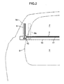
- FIG. 2 is a rear view showing the vehicle rear structure according to the first embodiment.
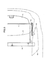
- FIG 3 is a top plan view showing the vehicle rear structure according to the first embodiment.
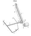
- FIG 4 is a perspective view showing a specific structure of an up-down drive means for slidingly displacing a pull bar.
- FIG. 5 is a cross-sectional view taken along the line A-A in FIG 1.
- FIG. 6 is a cross-sectional view taken along the line B-B in FIG 1.
- FIG. 7 is a cross-sectional view taken along the line C-C in FIG. 1.
- FIG 8 is a schematic diagram showing a trim member, viewed outwardly from a passenger compartment.
- FIG. 9 is a side view showing a tonneau-cover opening/closing mechanism according to a second embodiment of the present invention.
- FIG. 10 is a rear view showing the tonneau-cover opening/closing mechanism according to the second embodiment.
- FIG. 11 is a top plan view showing the tonneau-cover opening/closing mechanism according to the second embodiment.
- FIG 12 is a perspective view showing a specific structure of a coupling lever and a guide lever.
- FIG. 13 is an explanatory view showing a pull-bar guide direction and others of the guide rail.
- FIGS. 14A & 14B, each is an explanatory diagram showing a relationship between a closing-operation direction and a guide direction.
- FIGS. 1 to 3 shows a vehicle rear structure according to a first embodiment of the present invention. This vehicle rear structure comprises a
tailgate 3 adapted to be swingingly displaced about an upper hinge 1 provided in a rear of a vehicle body so as to openably cover arear opening 2, atonneau cover 6 adapted to be disposed to cover an upper side of arear cargo compartment 5 defined in front of therear opening 2 and in the rear of aseat back 4 of a passenger seat (rear seat), apull bar 6 provided at a rear end of thetonneau cover 6, and a pair of right andleft guide rails 8 slidably supporting respective opposite right and left ends of thepull bar 7. In FIGS. 1 to 3, thereference numeral 9 indicates amounting line of a sealing member to be mounted along a periphery of therear opening 2. - The
tonneau cover 6 comprises a sheet-like member associated with a retractingcase 10 positioned along an upper region of a rear surface of theseat back 4, and apull bar 7 supported by theguide rail 8, so as to extend between thepull bar 7 and the retractingcase 10. Theretractor case 10 houses a retracting mechanism which applies a biasing force to thetonneau cover 6 in a retracting direction. Specifically, a given tension corresponding to the biasing force of the retracting mechanism is constantly given to thetonneau cover 6, and thetonneau cover 6 is extracted from theretractor case 10 according to an after-mentioned opening/closing operation of thetonneau cover 6. As shown in FIG. 4, acover plate 11 composed of a synthetic resin plate is integrally formed with thepull bar 7 to protrude from a rear surface of thepull bar 7 so as to cover an upper side of a rear space of therear cargo compartment 5. A rear end of thetonneau cover 6 is fixed to thepull bar 7 through engagement means (not shown) or the like. - The
pull bar 7 has laterally opposite ends each held by aslider 12 adapted to be slidingly displaced along theguide rail 8. Specifically, theslider 12 is adapted to be moved upwardly and downwardly by up-down drive means 13. The up-down drive means 13 comprises: adrive cable 14 extending along theguide rail 8 and having theslider 12 fixed thereto at a given position; adrive roller 15 and a drivenroller 16 which are positioned at respective opposite upper and lower ends of theguide rail 8 and wound by thedrive cable 14; and adrive motor 17 adapted to rotationally drive thedrive roller 15. Thus, thedrive roller 15 is rotated according to a driving force of thedrive motor 17, and thereby theslider 12 is displaced together with thedrive cable 14 to move thepull bar 7 and the rear end of thetonneau cover 6. - As shown in FIG. 1, each of the right and
left guide rails 8 is positioned in a downwardly-inclined posture relative to a rearward direction, when viewed from a lateral side surface of the vehicle, i.e., in a side view of the vehicle. As shown in FIG 2, theguide rails 8 are positioned parallel to each other along a vertical direction, when viewed from a rear end of the vehicle, i.e., in a rear view of the vehicle. Further, each of theguide rails 8 has an upper portion which is located at a position overlapping a body (an inward sidewall surface of an inner pillar) of a corresponding one of a pair of right and leftrear pillars 18 formed in the rear of the vehicle, in the rear view of the vehicle ,and in front of therear pillar 18 in the side view of the vehicle (specifically, at a position overlapping a rear edge portion of aquarter window 19 positioned in front of therear pillar 18 in the side view of the vehicle, and a position adjacent to an inward surface of the quarter window in the rear of the vehicle, as shown in FIG. 1). - That is, in the vehicle having the
rear pillars 18 each inclined such that an upper end thereof is located inwardly relative to a lower end thereof in the rear view of the vehicle, the upper portion of theguide rail 18 is located most adjacent to thequarter window 19 in the rear view of the vehicle. Further, the upper portion of theguide rail 18 is located along an opaque light-shielding region 20 formed in a periphery of thequarter window 19 through an application of black ceramic paint or the like, and a portion of therear pillar 18 on the side of thequarter window 19, i.e., a flange 21 of therear pillar 18 located at a front edge thereof, as shown in FIG. 5. - The
rear pillar 18 includes anouter panel 18a and aninner panel 18b which are formed withflanges flanges flanges guide rail 8 is positioned in a downwardly-inclined posture relative to the rearward direction with an inclination angle closer to a horizontal direction than that of therear pillar 18. Thus, as shown in FIGS. 6 and 7, theguide rail 8 has a lower portion which is located at a position overlapping the body of therear pillar 18 in the side view of the vehicle and on the inside of therear pillar 18 in the rear view of the vehicle. - As above, in the vehicle having the
guide rail 8 positioned in the downwardly-inclined posture relative to the rearward direction in the side view of the vehicle, theguide rail 8 is positioned in a downwardly-inclined posture relative to the rearward direction with an inclination angle closer to a horizontal direction than that of therear pillar 18. Thus, as shown in FIGS. 6 and 7, the lower portion of theguide rail 8 is located opposed to the body of therear pillar 18, i.e., a portion of the inner pillar (inner panel) except for the flange 21, in a width or lateral direction of the vehicle, and frontwardly relative to a rear edge of therear pillar 18. That is, the lower portion of theguide rail 8 is located at a position overlapping therear pillar 18 in the side view of the vehicle. - As shown in FIGS. 5 to 7, the
guide rail 8 includes afront plate 22 supporting a front surface of theslider 12, a side plate supporting an outward surface of theslider 12, and aguide groove portion 24 continuously extending between thefront plate 22 and theside plate 23. Further, a drivenportion 25 of theslider 12 to be driven by thedrive cable 14 is disposed inside theguide groove portion 24. As shown in FIGS. 5 and 7, the upper and lower portions of theguide rail 8 are mounted to the inward side surface of therear pillar 18 through mountingbrackets - A
trim member 28 is disposed on the side of an interior space of the vehicle relative to therear pillar 18 to cover the inward side surface of the rear pillar 18 (see FIG. 8). As shown in F1GS. 5 and 7, thistrim member 28 includes asidewall plate 29 disposed opposed to the inward sidewall surface of therear pillar 18, and afront wall plate 30 extending continuously from a front edge of thesidewall plate 29. Thesidewall plate 30 of thetrim member 28 is disposed in spaced-apart relation to theinner panel 18b of therear pillar 18 with a given distance therebetween, in such a manner as to extend rearwardly from a front edge thereof in a given inclination direction to have a rear edge located inwardly relative to the front edge, in a horizontal cross-sectional view thereof. Thefront wall plate 30 is disposed to extend rearwardly in an inclination direction opposite to that of the sidewall plate 29 (i.e., in such a manner as to allow an outward edge thereof to be located on the side of the rear end of the vehicle) to have a rear edge oriented toward a rear edge portion of thequarter window 19. - Thus, the
sidewall plate 29 and thefront wall plate 30 form a V-shapedprotrusion 31 protruding frontwardly in a top plan view of the vehicle, at a front edge of thetrim member 28. Further, thesidewall plate 29 of thetrim member 28 disposed in spaced-apart relation to the inward sidewall surface of therear pillar 18 defines astorage space 32 for storing theguide rail 8 and other component, in cooperation with therear pillar 18. - In the above structure, in response to a manual operation of opening the
tailgate 3, an open switch (not shown) is turned on to rotate thedrive motor 17 in a normal direction so as to drive thedrive roller 15 and thedrive cable 14. Thus, theslider 12 fixed to each of the lateral ends of thepull bar 7 is moved upward from a lower position, i.e., a tonneau-cover close position, to an upper position, i.e., a tonneau-cover open position, along theguide rail 8. In this manner, the rear end of thetonneau cover 6 is moved to the upper open position to facilitate an operation of putting/taking articles in/out of the rear cargo compartment 5 (see the tow-dot chain line in FIG. 1). - Then, in response to a manual operation of closing the
tailgate 3, a close switch (not shown) is turned on to rotate thedrive motor 17 in a reverse direction so as to drive thedrive roller 15 and thedrive cable 14. Thus, Thus, theslider 12 fixed to each of the lateral ends of thepull bar 7 is moved downward from to the upper position, i.e., the tonneau-cover open position to the lower position, i.e., the tonneau-cover close position, along theguide rail 8. In this manner, the rear end of thetonneau cover 6 is moved to the lower close position to cover articles in the rear cargo compartment 5 (see the solid line in FIG 1). - As above, in the vehicle rear structure comprises the
tailgate 3 adapted to openably cover therear opening 2 defined between the pair of right and leftrear pillars 18 formed in the rear of the vehicle body, thetonneau cover 6 adapted to be disposed to cover an upper side of therear cargo compartment 5 located in front of therear opening 2, thepull bar 7 provided at the rear end of thetonneau cover 6, and the pair of right andleft guide rails 8 slidably supporting the respective opposite right and left ends of thepull bar 7, wherein thepull bar 7 is adapted to be slidingly displaced along theguide rails 8 so as to allow the rear end of thetonneau cover 6 to be moved upwardly and downwardly, the right andleft guide rails 8 are positioned parallel to each other in the rear view of the vehicle, and the upper portion of each of theguide rails 8 is located at a position overlapping a corresponding one of therear pillars 18 in the rear view of the vehicle and in front of therear pillar 18 in the side view of the vehicle. Further, the lower portion of theguide rail 8 is located at a position overlapping therear pillar 18 in the side view of the vehicle and on the inside of saidrear pillar 18 in the rear view of the vehicle. Thus, the rear end of thetonneau cover 6 can be displaced upwardly and downwardly along theguide rails 8 in a simplified structure without disadvantages, such as deterioration in rearward visibility, due to decrease in distance between the right and left guide rails 8. - More specifically, the
rear pillar 18 positioned in the side (lateral) edge of therear opening 2 is inclined such that the upward end is located inwardly in the rear view of the vehicle. Thus, if the right andleft guide rails 8a as indicated by the broken line in FIG. 2 are positioned parallel to each other and located inwardly relative to therear pillar 18 in the entire length thereof, lower ends of theguide rails 8a will inevitably protrude inwardly toward therear opening 2. In contrast, when the upper portion of theguide rail 8 is located at a position overlapping a corresponding one of therear pillars 18 in the rear view of the vehicle and in front of therear pillar 18 in the side view of the vehicle, theguide rails 8 can be positioned parallel to each other while preventing interference with therear pillar 18 having inwardly-inclined upper end, and sufficiently assuring the distance therebetween. - Thus, the
pull bar 7 can be slidingly displaced smoothly along theguide rails 8 while constantly supporting the right and left ends of thepull bar 7 by theguide rails 8 without employing a complicated mechanism, such as theprotrudable pins 8 capable of protruding in a variable manner as disclosed in the aforementioned conventional technique. Further, the above vehicle rear structure can prevent deterioration in rearward visibility and in user-friendliness during an operation of putting and taking articles in/out of therear cargo compartment 5, due to obstruction/hindrance of theguide rails 8 and sufficiently ensure a width dimension of thetonneau cover 6 to be disposed between the guide rails 8. - The lower portion of the
rear pillar 18 is located outwardly relative to the upper portion thereof. Thus, the lower portion of theguide rail 8 can be located at a position overlapping therear pillar 18 in the side view of the vehicle, and on the inside of saidrear pillar 18 in the rear view of the vehicle. When the lower portion of theguide rail 8 is located at a position overlapping therear pillar 18 in the side view of the vehicle, thepull bar 7 can be moved to a rearward position by slidingly displacing thepull bar 7 along theguide rails 8 to the tonneau-cover close position, so as to provide an advantage of being able to effectively cover articles in therear cargo compartment 5 by thetonneau cover 6. - In the first embodiment, in the vehicle having the
quarter window 19 positioned in front of therear pillar 18, the upper portion of theguide rail 8 is located at a position overlapping thequarter window 19 in the side view of the vehicle, and at a position adjacent to an inward surface of thequarter window 19 in the rear view of the vehicle. This vehicle rear structure has an advantage that the distance of the right andleft guide rails 8 can be further increased while preventing the upper portion of theguide rail 8 from interfering with therear pillar 18. - Particularly, in the vehicle having the opaque light-shielding
region 20 in the periphery of thequarter window 19 as in the first embodiment, when the upper portion of theguide rail 8 is located at a position overlapping the light-shieldingregion 20 in the side view of the vehicle, the light-shieldingregion 20 can advantageously prevent theguide rail 8 from becoming visible from outside through thequarter window 19 even if the upper portion of theguide rail 8 is located adjacent to the inward surface of thequarter window 19 in the side view of the vehicle. Thus, an aesthetic appearance of the vehicle can be adequately maintained. - In the first embodiment, in the vehicle having the
rear pillar 18 inclined such that an upper end thereof is located inwardly relative to a lower end thereof in the rear view of the vehicle, theguide rail 18 is positioned such that the upper portion thereof is located most adjacent to thequarter window 19. Thus, this vehicle rear structure can prevent theguide rail 8 from interfering with therear pillar 18, and can maximize the distance between the right andleft guide rails 8 while allowing theguide rails 8 to be positioned parallel to each other. - Further, when the upper portion of the
guide rail 8 is located along the flange 21 of therear pillar 18 formed on the side of thequarter window 19 as in the first embodiment, the upper portion of theguide rail 8 can be arranged while keeping away from the body (inward sidewall surface) of therear pillar 18. Thus, this vehicle rear structure has advantages of being able to ensure the distance between the right andleft guide rails 8 while preventing theguide rail 8 from interfering with therear pillar 18, and to effectively prevent theguide rail 8 from becoming visible from outside through thequarter window 19. - In the first embodiment, in the vehicle rear structure including the
outer panel 18a and theouter panel 18b which haveflanges rear pillar 18 in such a manner as to extend vertically in the rear of the vehicle body, thequarter window 19 positioned in front of therear pillar 18, and the trim member covering the inward sidewall surface of therear pillar 18, the trim member has thesidewall plate 29 extending rearwardly from a front edge thereof in a given inclination direction to have a rear edge located inwardly relative to the front edge, in a horizontal cross-sectional view thereof, and thefront wall plate 30 extending continuously and rearwardly from the front edge of the sidewall plate in an inclination direction opposite to that of thesidewall plate 29 to have a rear edge oriented toward a rear edge portion of thequarter window 19. Thus, the inward sidewall surface of therear pillar 18 can be advantageously covered by thetrim member 28 without deterioration in rearward visibility. - Specifically, an outwardly-oriented visual line of a passenger seated in a passenger seat disposed in front of the
rear pillar 18 is oriented rearwardly, i.e., a visual line J of the passenger viewing the outside through thequarter window 19 positioned in front of therear pillar 18, is directed in a rearward and outward direction which is aliened with the inclination direction of thefront wall plate 30. Thus, in the case where thetrim member 28 is disposed to cover the inward wall surface of therear pillar 18, the above vehicle rear structure has an advantage of being able to effectively prevent the visual line J of the passenger from being blocked due to the presence of thefront wall plate 30 so as to adequately ensure visibility through thequarter window 19. - The chevron-shaped
protrusion 31 composed of thesidewall plate 29 and thefront wall plate 30 of thetrim member 28 is formed at the front edge of thetrim member 28 in the top plan view of the vehicle, and thesidewall plate 29 of thetrim member 28 is disposed in spaced-apart relation to the inward wall surface of therear pillar 18 to define the givenstorage space 32 between thetrim member 28 and therear pillar 18. Thus, the above vehicle rear structure has advantages of being able to define a relativelylarge storage space 32 between thetrim member 32 and therear pillar 18 while preventing the visual line J of the passenger due to the presence of thetrim member 28, and store theguide rail 8, wire harnesses and other component using the storage space. - In place of the above structure designed to rotationally drive the
drive roller 15 according to the driving force of thedrive motor 17 so as to slidingly displace theslider 12 along theguide rail 8 together with thedrive cable 14, a screw-type feed control mechanism adapted to screw-feed theslider 12, or up-down means having a drive cylinder adapted to push and pull theslider 12, may be used for displacing thepull bar 7 upwardly and downwardly along the guide rails based on the opening/closing operation of thetailgate 3. Alternatively, theslider 12 may be slidingly displaced by a passenger's manual operation after the opening/closing operation of thetailgate 3 to displace thepull bar 7 upwardly and downwardly. - The first embodiment has been described based on one example where a given retracting tension is given to the
tonneau cover 6 using a retracting mechanism housed in the retractor case positioned along the upper portion of the rear surface of the seat back 4 so as to prevent thetonneau cover 6 from sagging when thepull bar 7 is slidingly displaced along the guide rails based on the opening/closing operation of thetailgate 3. In place of this structure, thetonneau cover 6 may be made of a stretchable material to prevent the sagging of thetonneau cover 6 in response to the upward/downward movement without providing the above retracting mechanism. - FIGS. 9 to 11 show a tonneau-cover opening/closing mechanism according to a second embodiment of the present invention. This embodiment is generally different from the first embodiment in the following points. In this tonneau-cover opening/closing mechanism, the opposite right and left ends of the
pull bar 7 provided at the rear end of thetonneau cover 6 are coupled to thetailgate 3 so that a drive force based on the opening/closing operation of thetailgate 3 is transferred to thepull bar 7 to slidingly displace thepull bar 7 along aguide rail 38. Further, the tonneau-cover opening/closing mechanism includes acoupling link 33 adapted to move the rear end of thetonneau cover 6 in conjunction with the above movement, and a reinforcingmember 34 made of a synthetic resin and disposed on the side of a coupling portion between thetonneau cover 6 and thepull bar 7. A lateral portion of the rear end of thetonneau cover 6 and a lateral portion of thepull bar 7 are integrally clamped by the reinforcingmember 34. - Further, each of the lateral ends of the
pull bar 7 is provided with aconnection bracket 35 for connecting thetonneau cover 6 to thecoupling link 33. Thisconnection bracket 35 includes abase plate 36 slidably supported along an inside surface of theguide rail 38. Anengagement hole 37 for thecoupling link 33 is formed in a rear portion of the base plate, and aU-shaped engagement portion 39 having a rear end with an opening is formed on an inward surface of thebase plate 36 to protrude,inwardly from the inward surface. The lateral end of thepull bar 7 is disengageably engaged with theengagement portion 39, and this engaged state of thepull bar 7 is held by the biasing force of the retracting mechanism. - The
coupling link 33 includes an upper-end pivotedportion 40 extending horizontally, a downwardly-extendingportion 41 extending obliquely rearwardly and downwardly from an inward end of the upper-end pivotedportion 40, abent portion 42 extending obliquely frontwardly and downwardly from a lower end of the downwardly-extendingportion 41, and a lower-end pivotedportion 43 extending horizontally and outwardly from a lower end of thebent portion 42. For example, thecoupling link 33 is prepared by subjecting a round bar to a bending process. - The lower-end pivoted
portion 43 of thecoupling link 33 has an outward end inserted into theengagement hole 37 of theconnection bracket 35 and a guide groove of theguide rail 38. Anut 45 is screwed on the inserted end to provide an engagement between the lower-end pivotedportion 43 and theguide rail 38. Further, the upper-end pivotedportion 40 of thecoupling link 33 has an outward end mounted to an inward surface of thetailgate 3 through a mountingbracket 46 to allow thepull bar 7 to be coupled to thetailgate 3. - In the
coupling link 33, a protruding amount of the lower-end pivotedportion 43 is set at a value greater than that of the upper-end pivotedportion 40. Further, each of the downwardly-extendingportion 41 and thebent portion 42 is disposed in a inclined posture to extend downwardly and outwardly in the rear view of the vehicle. Thus, as shown in FIGS. 10 and 1, a rail-side pivoted point L2, i.e., a coupling point of the lower-end pivotedportion 43 to theconnection bracket 35, is located outwardly relative to a tailgate-side pivoted point L1, i.e., a coupling point of the upper-end pivotedportion 40 to thetailgate 3. Further, the downwardly-extendingportion 41 of thecoupling link 33 is located inwardly relative to the side (lateral) edge of therear opening 2. An imaginary line L connecting the tailgate-side pivoted point L1 and the rail-side pivoted point L2 is inclined to be located laterally outwardly more and more toward a lower end. That is, the imaginary line L is located along therear pillar 18 defining the side edge of therear opening 2 inclined in an upwardly-tapering manner. - The
coupling link 33 is positioned such that thebent portion 42 thereof extends obliquely frontward relative to the downwardly-extendingportion 41. Thus, as shown in FIG 9, in the side view of the vehicle, thecoupling link 33 has a vertically intermediate portion formed in an L shape protruding rearwardly. Further, as shown in FIG. 10, in the rear view of the vehicle, the downwardly-extendingportion 41 and thebent portion 42 of thecoupling link 33 is located inclinedly in a downwardly-tapering manner to allow thecoupling link 33 to be disposed along the inward surface of therear pillar 18 forming the side edge of therear opening 2 when thetailgate 18 is closed. - The
guide rail 38 is formed of a plate member or the like having theguide groove 44 allowing the lower-end pivotedportion 43 of thecoupling link 33 to slidingly move therealong. Further, theguide rail 38 is formed to have a vertically central portion curved to protrude frontwardly and downwardly, in the side view of the vehicle, and the right andleft guide rails 38 are positioned parallel to each other along a vertical direction. Furthermore, theguide rail 38 is formed to have a pull-bar guide direction for guiding the pull-bar 7, which is arranged such that, during the closing operation of thetailgate 3, an angle between the pull-bar guide direction and an input direction of a closing operation-based driving force to be applied from thecoupling link 33 and theconnection bracket 35 thereto, is set at an obtuse angle. - More specifically, as shown in FIG 13, during the closing operation of the
tailgate 3, in the side view of the vehicle, the closing operation-based driving force is input in a direction A along a line connecting the upper-end pivotedportion 40 and the lower-end pivotedportion 43 of thecoupling link 33. The input direction A of the closing operation-based driving force and the guide direction B of theguide rail 38 is set to be located frontward relative to a line extending in a direction C orthogonal to the guide direction B of theguide rail 38 so as to allow an angle θ between the input direction A of the closing operation-based driving force and the guide direction B of theguide rail 38 to be set at an obtuse angle. - Along with the progress of the closing operation of the
tailgate 3, the input direction A of the closing operation-based driving force comes closer to a vertical direction. Further, in a final stage of the closing operation, the input direction A of the closing operation-based driving force acceleratingly decreases. Thus, in response to this change, the guide direction B of theguide rail 38 is gradually changed to a horizontal direction to maintain the angle θ between the input direction A of the closing operation-based driving force and the guide direction B of theguide rail 38 at an approximately constant value. In FIG 13, an arc-shaped line indicated by the reference code D is a locus of the upper-end pivotedportion 40 corresponding to the closing operation of thetailgate 3, and the reference code 1 is an upper hinge serving as a pivot of thetailgate 3. - As above, the angle θ between the input direction A of the closing operation-based driving force and the guide direction B of the
guide rail 38 is set at an obtuse angle. Thus, as shown in FIG 14A, in response to the closing operation-based driving force F input from the lower-end pivotedportion 43 of the coupling link 33a to thepull bar 7, a moving force G will act to allow the lower-end pivotedportion 43 of thecoupling link 33 and thepull bar 7 to be slidingly displaced along the guide rails 38. Further, as shown in FIG. 14B, in response to a decrease in the angle θ, the moving force G decreases, and a component force H of the closing operation-based driving force F acting in a direction C orthogonal to the guide direction B increases. Thus, a frictional force expressed as a value calculated by multiplying the component force H by a friction coefficient µ, i.e., a frictional resistance caused when the lower-end pivotedportion 43 of thecoupling link 33 is slidingly moved along the guide rails 38, is apt to increase. - According to an experimental test on a frictional force caused when the
pull bar 7 and the lower-end pivotedportion 43 of thecoupling link 33 is slidingly displaced downwardly, it has been proven that, if the angle θ is 110° or more, he pullbar 7 and the lower-end pivotedportion 43 of thecoupling link 33 can be slidingly displaced downwardly against the frictional force. Based on this experimental result, it has been verified that, when the angle θ between the input direction A of the closing operation-based driving force and the guide direction B of theguide rail 38 is set at 110° or more, thepull bar 7 can be slidingly displaced along the guide rails smoothly correspondingly to a driving force input from thecoupling link 33 into thepull bar 7 during the closing operation thetailgate 3, to move thetonneau cover 6 from the upper open position to the lower close position. - In an initial stage of the closing operation the
tailgate 3, i.e., when the upper-end pivotedportion 40 is located at the upper end of theguide rail 38, a relatively large frictional force acts. For slidingly displacing thepull bar 7 smoothly against such a static frictional force to move thetonneau cover 6 from the upper open position to the lower close position, the angle θ between the input direction A of the closing operation-based driving force and the guide direction B of theguide rail 38, at the upper end of theguide rail 38 is preferably set at a value greater than that the vertically intermediate portion and the lower portion of theguide rail 38, for example, at about 135°. - Further, in a portion of the
guide rail 38 where the angle θ between the input direction A of the closing operation-based driving force and the guide direction B of theguide rail 38 is changed, i.e., a portion located between the upper end of theguide rail 38 where the angle θ is set at a relatively large value (about 135°) than that of the lower portion, and the vertically intermediate portion theguide rail 38 where the angle θ is set at a relatively small value (about 110°), the pull-bar guide direction B of theguide rail 38 is arranged such that the angle θ is continuously (linearly) changed from 135° to 110°. - The pull-bar guide direction B at the lower end of the
guide rail 38, i.e., the pull-bar guide direction B in the final stage of the closing operation thetailgate 3, is set at an approximately horizontal direction, as shown in FIG. 13. Further, as shown in FIG. 9, in the side view of the vehicle, the upper portion of theguide rail 38 is located in frontwardly spaced-apart relation to therear opening 2 defined by therear pillars 18 extending approximately linearly in a downwardly-inclined posture relative to the rearward direction, and the lower portion of theguide rail 38 is located closer to therear opening 2. - As above, the tonncau-cover opening/closing mechanism according to the second embodiment includes the
coupling link 33 coupling the pair of right and left guides rails slidably supporting the right and left ends of thepull bar 7 provided at the rear end of thetonneau cover 6, and the right and left ends of thepull bar 7, to thetailgate 3. Thecoupling link 33 is adapted to transfer a driving force F based on the opening/closing operation of thetailgate 3, to thepull bar 7 therethrough, so as to allow the rear end of thetonneau cover 6 to be moved upwardly and downwardly in conjunction with a sliding displacement of thepull bar 7 along theguide rail 38 according to the driving force F. Theguide rail 38 is formed, in the side view of the vehicle, to include the vertically central portion curved to protrude frontwardly and downwardly, and have a pull-bar guide direction for guiding the pull-bar 7, which is arranged such that, during the closing operation of thetailgate 7, an angle between the pull-bar guide direction B of theguide rail 38 and the input direction A of the closing operation-based driving force F to be applied from thecoupling link 33 to thepull bar 7, is set at an obtuse angle. Thus, the rear end of thetonneau cover 6 can be moved upwardly and downwardly in conjunction with the opening/closing operation of thetailgate 3 in a simplified structure to move thetonneau cover 6 between the lower close position and the upper open position. - Specifically, the
pull bar 7 is adapted to be slidingly displaced along the guide rails 38 in conjunction with the opening/closing operation of thetailgate 3 to move the rear end of thetonneau cover 6 upwardly and downwardly. Thus, the rear end of thetonneau cover 6 can be moved upwardly and downwardly in conjunction with the opening/closing operation of thetailgate 3 without providing driving means separately to move thetonneau cover 6 between the lower close position and the upper open position. During the opening operation of thetailgate 3, the rear end of thetonneau cover 6 can be moved to the upper open position to facilitate an operation of putting/taking articles in/out of therear cargo compartment 5. Further, during the closing operation of thetailgate 3, the rear end of thetonneau cover 6 can be moved to the lower close position to cover articles in therear cargo compartment 5. - Thus, the right and left ends of the
pull bar 7 can be constantly supported by the guide rails 38 without employing particular means, such as the protrudable pins capable of protruding in a variable manner as disclosed in the aforementioned conventional technique to provide a simplified structure. Further, the lower end of theguide rail 38 can be located outwardly relatively therear opening 2 as indicated by the solid line in FIG. 11 while preventing the lower end of theguide rail 38a from being located inwardly relative to therear opening 2, due to the right and left side edges of the rear opening inclined in an upward tapering manner in the rear view of the vehicle, as indicated by the broken line in FIG. 10. This makes it possible to prevent the guide rails 38 from hindering the operation of putting/taking articles on/out of therear cargo compartment 5 and sufficiently ensure the width dimension of thetonneau cover 6 to be disposed between the guide rails 38. - Further, the guide direction B of the
guide rail 38 is arranged such that the angle θ between the input direction A of the closing operation-based driving force F acting from thecoupling link 33 to thepull bar 7 and the guide direction B of theguide rail 38, during the closing operation thetailgate 3, is set at an obtuse angle. Thus, even when theguide rail 38 is positioned frontward relative to therear opening 2 of the vehicle by a given distance, the rear end of the tonneau cover can be smoothly moved upwardly and downwardly in conjunction with the closing operation thetailgate 3 while suppressing an increase in frictional force caused when thepull bar 7 is slidingly displaced along the guide rails 38 during the closing operation of thetailgate 3 in an open state. - That is, an inclination angle of the closing operation-based driving force to be input from the
tailgate 3 in the open state into thepull bar 7 through thecoupling link 33, with respect to a horizontal plane, becomes smaller as the positing of theguide rail 38 is shifted toward an front end of the vehicle relative to the rear opening of the vehicle, and the input direction A of the closing operation-based driving force comes closer to a horizontal direction. Consequently, an effective force for the downward movement along the guide rail is apt to decrease. In this regard, theguide rail 38 formed to include the vertically central portion curved to protrude frontwardly and downwardly, in the side view of the vehicle, and the guide direction B of theguide rail 38 is arranged such that the angle θ between the input direction A of the closing operation-based driving force F acting from thecoupling link 33 to thepull bar 7 and the guide direction B of theguide rail 38, during the closing operation thetailgate 3, is set at an obtuse angle. In this case, even if theguide rail 38 is positioned frontward relative to therear opening 2 of the vehicle by a relatively long distance, a force G allowing thepull bar 7 and the lower-end pivotedportion 43 of thecoupling link 33 to be slidingly displaced downward according to the closing operation-based driving force F can be sufficiently ensured as shown in FIG. 14A to smoothly drive the rear end of thetonneau cover 6 upwardly and downwardly in conjunction with the opening/closing operation thetailgate 3. - In the second embodiment, the angle θ between the input direction A of the closing operation-based driving force and the guide direction B of the
guide rail 38 is set at a larger value in an upper end of theguide rail 38 than in the vertically intermediate portion of theguide rail 38. Thus, in the initial stage of the closing operation of thetailgate 3 involving static friction, this structure has an advantage of being able to sufficiently ensure the moving force G to be input from thecoupling link 33 into thepull bar 7 according to the closing operation-based driving force F so as to allow the lower-end pivotedportion 43 of thecoupling link 33 and thepull bar 7 to be slidingly displaced downwardly, and to suppress the frictional resistance expressed as a value calculated by multiplying the component force H of the closing operation-based driving force F acting in the direction C orthogonal to the guide direction B of theguide rail 38 by a friction coefficient µ, to a sufficiently low value so as to allow the closing operation of thetailgate 3 to be smoothly performed. - In the second embodiment, the pull-bar guide direction B in the lower end of the
guide rail 7 is set at an approximately horizontal direction. This provides, an advantage of being able to effectively prevent the occurrence of an undesirable situation where a guide position of thepull bar 7 is changed to a certain extent in a close position of thetailgate 3 due to production error or deformation during use, and consequently a vertical position of thetonneau cover 6 is changed. This makes it possible to prevent an intended height and direction of thetonneau cover 6 from being changed when thetonneau cover 6 is moved downwardly to the close position. - Particularly, in a certain portion of the
guide rail 38 where the angle θ between the pull-bar guide direction B and the input direction A of the closing operation-based driving force is changed, the angle θ is continuously changed. This makes it possible to effectively prevent the occurrence of wobbling during a sliding movement of thepull bar 7 due to sudden change of the angle θ at the portion, to allow thepull bar 7 to be slidingly displaced along the guide rails 38 smoothly. - In the second embodiment, the
guide rail 38 is positioned such that, in the side view of the vehicle, the upper portion of theguide rail 38 is located in frontwardly spaced-apart relation to therear opening 2 extending approximately linearly in a downwardly-inclined posture relative to the rearward direction, and the lower portion of theguide rail 38 is located closer to therear opening 2, so that, when thetailgate 3 is closed, thepull bar 7 and the rear end of thetonneau cover 6 are moved to a position adjacent to the side edges of therear opening 2 while positioning the right andleft guide rails 38 parallel to each other and sufficiently ensuring the distance between the guide rails 38. - The above upper portion of the
guide rail 38 located in frontwardly spaced-apart relation to therear opening 2 makes it possible to prevent the upper portion of thecoupling link 33 being moving upwardly along theguide rail 38 during the opening operation of thetailgate 3, from interfering with the side edge of therear pillar 38. Further, the right andleft guide rails 38 can be positioned parallel to each other while sufficiently ensuring the distance between the guide rails without interference between the guide rails 38 and therear pillars 18 in the rear view of the vehicle. Further, when the tailgate in a closed state, thepull bar 7 and the rear end of thetonneau cover 6 are moved to a position adjacent to the side edges of therear opening 2. Thus, approximately the entire area of therear cargo compartment 5 including a rear region thereof can be advantageously covered by thetonneau cover 6 to provide a sufficient function of covering articles, to the tonneau cover. - In the second embodiment, the rail-side pivoted point L2 of the
coupling link 33 serving as a coupling point of the lower-end pivotedportion 43 to theguide rail 38 is set to be located outwardly relative to the tailgate-side pivoted point L1 of thecoupling link 33 serving as a coupling point of the upper-end pivotedportion 40 to thetailgate 3, in the rear view of the vehicle. This makes it possible to prevent the upper portion of thecoupling link 33 from interfering the side edge of therear opening 2 during the opening operation of thetailgate 3, and allow the rear end of thetonneau cover 6 to be moved up to a sufficient height during the opening operation of thetailgate 3. Further, the guide rails 38 can be positioned laterally outward to sufficiently ensure the width dimension of thetonneau cover 6. - Specifically, if the upper end of the
guide rail 38 is designed to extend up to a position adjacent to an upper edge of therear opening 2 to allow the rear end of thetonneau cover 6 to be largely moved upwardly during the opening operation of thetailgate 3, the upper portion of thecoupling link 33 moved upward along theguide rail 34 during the opening operation of thetailgate 3 is likely to interfere with the side edge of therear opening 2 inclined in an upwardly tapering manner in the rear view of the vehicle, Moreover, if theguide rail 38 connected with the lower-end pivotedportion 43 of thecoupling link 33 is positioned inwardly, the distance between the right andleft guide rails 38 will inevitably decrease and hinder the operation of putting/taking articles in/out of the rear cargo compartment (see the broken line in FIG 10). - In contract, the rail-side pivoted point L2 of the
coupling link 33 set to be located outwardly relative to the tailgate-side pivoted point L1 of thecoupling link 33 as in the second embodiment provides advantages that even when the upper end of theguide rail 38 is designed to extend up to a position adjacent to an upper edge of therear opening 2 to allow the rear end of thetonneau cover 6 to be largely moved upwardly during the opening operation of thetailgate 3, the upper portion (downwardly-extending portion 41) of thecoupling link 33 located adjacent to the tailgate-side pivoted point L1 can be located inwardly relative to the side edge of therear opening 2. This makes it possible to prevent the upper end of thecoupling link 33 from interfering with the side edge of therear opening 2. Further, the rail-side pivoted point L1 is set to be located outwardly relative to the tailgate-side pivoted point L2. This makes it possible to increase the width dimension of thetonneau cover 6 to be disposed between the guide rails 38, and prevent the guide rails 38 from hindering the operation of putting/taking articles in/out of therear cargo compartment 5. - In the second embodiment, the
coupling link 33 is positioned such that thebent portion 42 thereof extends obliquely frontward relative to the downwardly-extendingportion 41 to form the vertically intermediate portion in an L shape in the side view of the vehicle. Thus, even when the upper-end pivotedpoint 40 of thecoupling link 33 is moved to the upper end of theguide rail 38 after thetailgate 3 is opened, as indicated by the two-dot chain line in FIG. 9, this arrangement can effectively prevent the upper portion of thecoupling link 33 from coming into contact with the upper edge of therear opening 2. - In the second embodiment, each of the downwardly-extending
portion 41 and thebent portion 42 of thecoupling link 33 is disposed in an inclined posture to extend downwardly and outwardly in the rear view of the vehicle, so that each of the downwardly-extendingportion 41 and thebent portion 42 of thecoupling link 33 is located along the side edge ofrear opening 2 during the closing operation of thetailgate 3. This makes it possible to prevent the upper portion of thecoupling link 33 from interfering with the side edge of therear opening 2 during the opening operation of the tailgate while preventing thecoupling link 33 from hindering rearward visibility. - In summary, In order to achieve the above object, as set forth in the one aspect of the invention, the present invention provides a vehicle rear structure which comprises a tailgate adapted to openably cover a rear opening defined between a pair of right and left rear pillars formed in a rear of a vehicle body, a tonneau cover adapted to be disposed to cover an upper side of a rear cargo compartment located in front of the rear opening, a pull bar provided at a rear end of the tonneau cover, and a pair of right and left guide rails slidably supporting respective opposite right and left ends of the pull bar. The pull bar is adapted to be slidingly displaced along the guide rails so as to allow the rear end of the tonneau cover to be moved upwardly and downwardly. The vehicle rear structure is characterized in that the right and left guide rails are positioned parallel to each other, when viewed from a rear end of the vehicle, i.e., in a rear view of the vehicle. Each of the guide rails has an upper portion located at a position overlapping a corresponding one of the rear pillars in the rear view of the vehicle, and in front of the rear pillar, when viewed from a lateral side surface of the vehicle, i.e., in a side view of the vehicle. Further, each of the guide rails has a lower portion located at a position overlapping the rear pillar in the side view of the vehicle.
- As a 2nd aspect of the present invention, the upper portion of the guide rail is located at a position overlapping a quarter window positioned in front of the rear pillar, in the side view of the vehicle, and at a position adjacent to an inward surface of the quarter window in the rear view of the vehicle.
- As a 3rd aspect of the present invention, in the vehicle rear structure, the quarter window has a periphery including an opaque light-shielding region, and the upper portion of the guide rail is located at a position overlapping the light-shielding region, in the side view of the vehicle.
- As a 4th aspect of the present invention, in the vehicle rear structure, each of the rear pillars is inclined such that an upper end thereof is located inwardly relative to a lower end thereof in the rear view of the vehicle, and the guide rail is positioned such that the upper portion thereof is located most adjacent to the quarter window in the rear view of the vehicle.
- As a 5th aspect of the present invention, in the vehicle rear structure, the rear pillar is formed with a flange on the side of the quarter window, and the upper portion of the guide rail is located along the flange in the side view of the vehicle.
- As a 6th aspect of the present invention, the vehicle rear structure includes an inner panel and an outer panel which, have flanges joined together to form the rear pillar in such a manner as to extend vertically in the rear of the vehicle body, a quarter window positioned in front of the rear pillar, and a trim member covering an inward sidewall surface of the rear pillar. The trim member includes a sidewall plate extending rearwardly from a front edge thereof in a given inclination direction to have a rear edge located inwardly relative to the front edge, in a horizontal cross-sectional view thereof, and a front wall plate extending continuously and rearwardly from the front edge of the sidewall plate in an inclination direction opposite to that of the sidewall plate to have a rear edge oriented toward a rear edge portion of the quarter window. A portion of the trim member consisting of the front wall plate and an frontward portion of the sidewall plate continuous with the front wall, and a portion of the rear pillar consisting of the flange located along an front edge thereof and a body of the inner panel continuous with the flange, define an in-trim storage space therebetween. The guide rail is disposed in the trim-based storage space.
- As a 7th aspect of the present invention, the vehicle rear structure includes a coupling link coupling the right and left ends of the pull bar to the tailgate. The coupling link is adapted to transfer a driving force based on an opening/closing operation of the tailgate, to the pull bar therethrough, so as to allow the rear end of the tonneau cover to be moved upwardly and downwardly in conjunction with a sliding displacement of the pull bar along the guide rail according to the driving force. The guide rail is formed, in the side view of the vehicle, to include a vertically central portion curved to protrude frontwardly and downwardly, and have a pull-bar guide direction for guiding the pull-bar, which is arranged such that, during the closing operation of the tailgate, an angle between the pull-bar guide direction and an input direction of the closing operation-based driving force to be applied from the coupling link to the pull bar, is set at an obtuse angle.
- As a 8th aspect of the present invention, in the vehicle rear structure, the angle between the pull-bar guide direction and the input direction of the closing operation-based driving force is set at a larger value in an upper end of the guide rail than in a vertically intermediate portion of the guide rail.
- As a 9th aspect of the present invention, in the vehicle rear structure, the pull-bar guide direction is set at an approximately horizontal direction in a lower end of the guide rail.
- As a 10th aspect of the present invention, in the vehicle rear structure, the angle between the pull-bar guide direction and the input direction of the closing operation-based driving force is continuously changed in a certain portion of the guide rail where the angle is changed.
- As a 11th aspect of the present invention, the vehicle rear structure includes a coupling link coupling the right and left ends of the pull bar to the tailgate. The coupling link is adapted to transfer a driving force based on an opening/closing operation of the tailgate, to the pull bar therethrough, so as to allow the rear end of the tonneau cover to be moved upwardly and downwardly in conjunction with a sliding displacement of the pull bar along the guide rail according to the driving force. In the rear view of the vehicle, a coupling point of the coupling link to the guide rail is set to be located outwardly relative to a coupling point of the coupling link to the tail gate.
- As a 12th aspect of the present invention, in the vehicle rear structure, the coupling link has a vertically intermediate portion located rearwardly relative to the remaining portion so as to allow the coupling link to be form in an L shape, in the side view of the vehicle.
- As a 13th aspect of the present invention, in the vehicle rear structure, the right and left rear pillars are inclined in upwardly tapering relation to each other, in the rear view of the vehicle, and the coupling link is inclined to extend along a side edge of the rear pillar.
- As above, in vehicle rear structure of the present invention as set forth in the 1st aspect of the present invention, the right and left guide rails are positioned parallel to each other in a rear view of the vehicle, and the upper portion of the guide rail is located at a position overlapping the rear pillar in the rear view of the vehicle and in front of the rear pillar in a side view of the vehicle. Further, the lower portion of the guide rail is located at a position overlapping the rear pillar in the side view of the vehicle, and on the inside of said rear pillar in the rear view of the vehicle. Thus, the rear end of the tonneau cover can be displaced upwardly and downwardly along the guide rails in a simplified structure without disadvantages, such as deterioration in rearward visibility, due to decrease in distance between the right and left guide rails.
- In the vehicle rear structure as set forth in the 2nd aspect of the present invention, in a vehicle having a quarter window positioned in front of a rear pillar, the upper portion of the guide rail is located at a position overlapping the quarter window in the side view of the vehicle, and at a position adjacent to an inward surface of the quarter window in the rear view of the vehicle. This vehicle rear structure has an advantage that the distance of the right and left guide rails can be further increased while preventing the upper portion of the guide rail from interfering with the rear pillar.
- In the vehicle rear structure as set forth in the 3rd aspect of the present invention, the light-shielding region can prevent the guide rail from becoming visible from outside even through the quarter window if the upper portion of the guide rail is located adjacent to the inward surface of the quarter window in the side view of the vehicle. Thus, an aesthetic appearance of the vehicle can be adequately maintained.
- In the vehicle rear structure as set forth in the 4th aspect of the present invention, in a vehicle having a rear pillar inclined such that an upper end thereof is located inwardly relative to a lower end thereof in the rear view of the vehicle, the guide rail is positioned such that the upper portion thereof is located most adjacent to the quarter window. This vehicle rear structure can prevent the guide rail from interfering with the rear pillar, and can maximize the distance between the right and left guide rails while allowing the guide rails to be positioned parallel to each other.
- In the vehicle rear structure as set forth in the 5th aspect of the present invention, the upper portion of the guide rail is located along the flange of the rear pillar formed on the side of the quarter window. Thus, the upper portion of the guide rail can be arranged while keeping away from a body of the rear pillar. Therefore, this vehicle rear structure has advantages of being able to ensure the distance between the right and left guide rails while preventing the guide rail from interfering with the rear pillar, and to effectively prevent the guide rail from becoming visible from outside through the quarter window.
- In the vehicle rear structure as set forth in the 6th aspect of the present invention, the pair of right and left guide rails slidably supporting the right and left ends of the pull bar provided at the rear end of the tonneau cover are disposed in the trim-based storage space. This vehicle rear structure has advantages of being able to sufficiently ensure the distance between the right and left guide rails while preventing deterioration in aesthetic value of a passenger compartment due to exposure of the guide rails, so as to prevent deterioration in rearward visibility and in user-friendliness during an operation of putting and taking articles in/out of the rear cargo compartment, due to obstruction/hindrance of the guide rails caused by a decrease in the distance between the right and left guide rails, and sufficiently ensure a width dimension of the tonneau cover to be disposed between the guide rails.
- In the vehicle rear structure as set forth in the 7th aspect of the present invention, the rear end of the tonneau cover can be moved upwardly and downwardly in conjunction with the tailgate opening/closing operation without providing driving means separately. In addition, the right and left guide rails can be positioned parallel to each other while sufficiently ensuring the distance therebetween in the rear view of the vehicle. Further, in an initial stage of the operation of closing the tailgate in the open position, this vehicle rear structure has an advantage of being able to suppress an increase in frictional resistance during a sliding movement of the pull bar along the guide rails.
- In the vehicle rear structure as set forth in the 8th aspect of the present invention, in the initial stage of the tailgate closing operation involving static friction, this vehicle rear structure has an advantage of being able to sufficiently ensure a driving force to be input from the coupling link into the pull bar based on the closing operation so as to allow the pull bar to be slidingly displaced downwardly, and to suppress the frictional resistance during the closing operation to a sufficiently low value so as to smoothly move the pull bar upwardly and downwardly based on the tailgate opening/closing operation.
- The vehicle rear structure as set forth in the 9th aspect of the present invention has an advantage of being able to effectively prevent the occurrence of an undesirable situation where a guide position of the pull bar is changed to a certain extent in a close position of the tailgate due to production error or deformation during use, and consequently a vertical position of the tonneau cover is changed. This makes it possible to prevent an intended height and direction of the tonneau cover from being changed when the tonneau cover is moved downwardly to the close position.
- In the vehicle rear structure as set forth in the 10th aspect of the present invention, in a certain portion of the guide rail where the angle between the pull-bar guide direction and the input direction of the closing operation-based driving force is changed, the angle is continuously changed. Thus, this vehicle rear structure can effectively prevent the occurrence of wobbling during a sliding movement of the pull bar due to sudden change of the above angle, to allow the pull bar to be slidingly displaced along the guide rails smoothly.
- In the vehicle rear structure as set forth in the 11th aspect of the present invention, the rear end of the tonneau cover can be moved upwardly and downwardly in conjunction with the tailgate opening/closing operation without providing driving means separately. In addition, the right and left guide rails can be positioned parallel to each other while sufficiently ensuring the distance therebetween in the rear view of the vehicle. Further, even when the upper end of the guide rail is designed to extend up to a position adjacent to an upper edge of the rear opening to allow the rear end of the tonneau cover to be largely moved upwardly during the tailgate opening operation, an upper portion of the coupling link located adjacent to the coupling point of the coupling link to the tailgate can be located inwardly relative to a side edge of the rear opening. This makes it possible to prevent the upper end of the coupling link from interfering with the side edge of the rear opening. Further, a coupling point of the coupling link to the guide rail is set to be located outwardly relative to a coupling point of the coupling link to the tail gate. Thus, this vehicle rear structure has advantages of being able to sufficiently ensure the distance between the right and left guide rails so as to increase the width dimension of the tonneau cover to be disposed between the guide rails, and prevent the guide rails from hindering the operation of putting/taking articles in/out of the rear cargo compartment.
- In the vehicle rear structure as set forth in the 12th aspect of the present invention, even in a vehicle where the upper end of the guide rail extends up to a position adjacent to the upper edge of the rear opening, and the upper portion of the guide rail is located in front of the rear opening, the coupling link can be bypassingly moved behind the upper edge of the rear opening through vertically intermediate portion. Thus, this vehicle rear structure has an advantage of being able to effectively prevent the coupling link from coming into contact with the upper edge of the rear opening.
- In the vehicle rear structure as set forth in the 13th aspect of the present invention, the coupling link is disposed to extend along a side edge of the rear opening. Thus, this vehicle rear structure has an advantage of being able to prevent the upper portion of the coupling link from interfering with the side edge of the rear opening during the tailgate opening operation while preventing the coupling link from hindering rearward visibility.
- Although the present invention has been fully described by way of example with reference to the accompanying drawings, it is to be understood that various changes and modifications will be apparent to those skilled in the art. Therefore, unless otherwise such changes and modifications depart from the scope of the present invention, hereinafter defined, they should be construed as being included therein.
Claims (13)
- A vehicle rear structure comprising:a tailgate (3) adapted to openably cover a rear opening (2) defined between a pair of right and left rear pillars (18) formed in a rear of a vehicle body;a tonneau cover (6) adapted to be disposed to cover an upper side of a rear cargo compartment (5) located in front of said rear opening (2);a pull bar (7) provided at a rear end of said tonneau cover (6); anda pair of right and left guide rails (8) slidably supporting respective opposite right and left ends of said pull bar (7),wherein said pull bar (7) is adapted to be slidingly displaced along said guide rails (8) so as to allow the rear end of said tonneau cover (6) to be moved upwardly and downwardly,
said vehicle rear structure being characterized in that:said right and left guide rails (8) arc positioned parallel to each other in a rear view of the vehicle; andeach of said guide rails (8) has an upper portion and a lower portion, said upper portion being located at a position overlapping a corresponding one of the rear pillars (18) in the rear view of the vehicle and in front of said rear pillar (18) in a side view of the vehicle, said lower portion being located at a position overlapping said rear pillar (18) in the side view of the vehicle. - The vehicle rear structure as defined in claim 1, wherein the upper portion of said guide rail (8) is located at a position overlapping a quarter window (19) positioned in front of the rear pillar (18), in the side view of the vehicle, and at a position adjacent to an inward surface of said quarter window (19) in the rear view of the vehicle.
- The vehicle rear structure as defined in claim 2, wherein:said quarter window (19) has a periphery including an opaque light-shielding region (20); andthe upper portion of said guide rail (8) is located at a position overlapping said light-shielding region (20) in the side view of the vehicle.
- The vehicle rear structure as defined in claim 2 or claim 3, wherein each of said rear pillars (18) is inclined such that an upper end thereof is located inwardly relative to a lower end thereof, in the rear view of the vehicle, wherein said guide rail (8) is positioned such that said upper portion thereof is located most adjacent to said quarter window (19) in the rear view of the vehicle.
- The vehicle rear structure as defined in one of claims 2 to 4, wherein:said rear pillar (18) is formed with a flange (20a, 20b) on the side of said quarter window (19); andthe upper portion of said guide rail (8) is located along said flange (20a, 20b) in the side view of the vehicle.
- The vehicle rear structure as defined in one of the preceding claim, which includes:an inner panel (18b) and an outer panel (18a) which have flanges (20a, 20b, 21a, 21b) joined together to form said rear pillar (18) in such a manner as to extend vertically in the rear of the vehicle body;a quarter window (19) positioned in front of said rear pillar (18); anda trim member (28) covering an inward sidewall surface of said rear pillar (18), said trim member (28) including:wherein:a sidewall plate (29) extending rearwardly from a front edge thereof in a given inclination direction to have a rear edge located inwardly relative to said front edge, in a horizontal cross-sectional view thereof; anda front wall plate (30) extending continuously and rearwardly from the front edge of said sidewall plate in an inclination direction opposite to that of said sidewall plate to have a rear edge oriented toward a rear edge portion of said quarter window (19),a portion of said trim member (28) consisting of said front wall plate (29) and an frontward portion of said sidewall plate (30) continuous with said front wall (29), and a portion of said rear pillar (18) consisting of the flange (20b) located along an front edge thereof and a body of said inner panel (18b) continuous with said flange (20b), define an in-trim storage space (32) therebetween; andsaid guide rail (8) is disposed in said trim-based storage space (32).
- The vehicle rear structure as defined in one of the preceding claims, which includes a coupling link (33) coupling the right and left ends of said pull bar (7) to said tailgate (3), said coupling link (33) being adapted to transfer a driving force based on an opening/closing operation of said tailgate (3), to the pull bar (7) therethrough, so as to allow the rear end of said tonneau cover (6) to bc moved upwardly and downwardly in conjunction with a sliding displacement of said pull bar (6) along said guide rail (38) according to said driving force,
wherein:said guide rail (38) is formed, in the side view of the vehicle, to include a vertically central portion curved to protrude frontwardly and downwardly, and have a pull-bar guide direction for guiding said pull-bar (7), which is arranged such that, during the closing operation of said tailgate (2), an angle (θ) between said pull-bar guide direction (B) and an input direction (A) of said closing operation-based driving force to be applied from said coupling link (33) to said pull bar (7), is set at an obtuse angle. - The vehicle rear structure as defined in claim 7, wherein said angle (9) between the pull-bar guide direction (B) and the input direction (A) of the closing operation-based driving force is set at a larger value in an upper end of said guide rail (38) than in a vertically intermediate portion of said guide rail (38).
- The vehicle rear structure as defined in claim 7 or 8, wherein said pull-bar guide direction (B) is set at an approximately horizontal direction in a lower end of said guide rail (38).
- The vehicle rear structure as defined in claim 9, wherein said angle (θ) between the pull-bar guide direction (B) and the input direction (A) of the closing operation-based driving force is continuously changed in a certain portion of said guide rail (38) where said angle is changed.
- The vehicle rear structure as defined in one of the preceding claims, which includes a coupling link (41) coupling the right and left ends of said pull bar (7) to said tailgate (2), said coupling link (41) being adapted to transfer a driving force based on an opening/closing operation of said tailgate (2), to the pull bar (7) therethrough, so as to allow the rear end of said tonneau cover (6) to be moved upwardly and downwardly in conjunction with a sliding displacement of said pull bar (7) along said guide rail (38) according to said driving force, wherein, in the rear view of the vehicle, a coupling point (L2) of said coupling link (41) to said guide rail (38) is set to be located outwardly relative to a coupling point (L1) of said coupling link (41) to said tail gate (2).
- The vehicle rear structure as defined in claim 11, wherein said coupling link (41) has a vertically intermediate portion located rearwardly relative to the remaining portion so as to allow said coupling link (41) to be form in an L shape in the side view of the vehicle.
- The vehicle rear structure as defined in claim 11 or 12, wherein said right and left rear pillars (18) are inclined in upwardly tapering relation to each other, in the rear view of the vehicle, wherein said coupling link (41) is inclined to extend along a side edge of said rear pillar (18).
Applications Claiming Priority (4)
| Application Number | Priority Date | Filing Date | Title |
|---|---|---|---|
| JP2005336849A JP4561609B2 (en) | 2005-11-22 | 2005-11-22 | Tonneau cover opening and closing device |
| JP2005336850A JP2007137356A (en) | 2005-11-22 | 2005-11-22 | Tonneau cover opening and closing device |
| JP2005351117A JP4670617B2 (en) | 2005-12-05 | 2005-12-05 | Car body rear structure |
| JP2005351118A JP4706461B2 (en) | 2005-12-05 | 2005-12-05 | Car body rear structure |
Publications (2)
| Publication Number | Publication Date |
|---|---|
| EP1787864A1 true EP1787864A1 (en) | 2007-05-23 |
| EP1787864B1 EP1787864B1 (en) | 2009-03-25 |
Family
ID=37743384
Family Applications (1)
| Application Number | Title | Priority Date | Filing Date |
|---|---|---|---|
| EP06024151A Ceased EP1787864B1 (en) | 2005-11-22 | 2006-11-21 | Vehicle rear structure |
Country Status (3)
| Country | Link |
|---|---|
| US (1) | US7537265B2 (en) |
| EP (1) | EP1787864B1 (en) |
| DE (1) | DE602006005885D1 (en) |
Cited By (12)
| Publication number | Priority date | Publication date | Assignee | Title |
|---|---|---|---|---|
| WO2009033981A1 (en) * | 2007-09-11 | 2009-03-19 | Brose Fahrzeugteile Gmbh & Co. Kg, Hallstadt | Adjustment device for a cover device in a motor vehicle |
| WO2013053456A1 (en) * | 2011-10-14 | 2013-04-18 | Brose Fahrzeugteile Gmbh & Co. Kommanditgesellschaft, Coburg | Trim assembly for a motor vehicle having a luggage compartment cover |
| FR2993834A1 (en) * | 2012-07-25 | 2014-01-31 | Cera | Covering device for covering luggage compartment of car, has guide rails extending between upper and lower ends such that deactivation of locking unit allows sliding of guide elements to allow shelf to be in partially folded configuration |
| US9016758B1 (en) | 2013-12-09 | 2015-04-28 | Ford Global Technologies, Llc | Tonneau cover gap hider for adjustable rear seats |
| EP2927055A1 (en) * | 2014-04-02 | 2015-10-07 | Cera APS | System for covering a luggage compartment of a motor vehicle |
| FR3026072A1 (en) * | 2014-09-24 | 2016-03-25 | Cera | SYSTEM FOR COVERING A LUGGAGE COMPARTMENT OF A MOTOR VEHICLE |
| EP3000661A1 (en) * | 2014-09-29 | 2016-03-30 | Cera APS | System for covering a luggage compartment of a motor vehicle |
| US9302627B1 (en) | 2014-11-18 | 2016-04-05 | Ford Global Technologies, Llc | Two-sided flexible tonneau cover having a planar forward extending cover member |
| US20160325687A1 (en) * | 2015-05-08 | 2016-11-10 | Herbert Walter | Protective device for a vehicle interior |
| FR3079796A1 (en) * | 2018-04-04 | 2019-10-11 | Cera Aps | AUTOMOTIVE VEHICLE LUGGAGE COMPARTMENT REPAIR SYSTEM |
| FR3082157A1 (en) * | 2018-06-12 | 2019-12-13 | Psa Automobiles Sa | DEVICE FOR MASKING A VEHICLE WELCOMING SPACE, WITH CANVAS COUPLED TO THE TAILGATE BY DEFORMABLE AND DISSYMMETRIC COUPLERS |
| FR3082158A1 (en) * | 2018-06-12 | 2019-12-13 | Psa Automobiles Sa | DEVICE FOR MASKING A VEHICLE WELCOMING SPACE, WITH CANVAS COUPLED TO THE TAILGATE BY CONNECTING RODS |
Families Citing this family (17)
| Publication number | Priority date | Publication date | Assignee | Title |
|---|---|---|---|---|
| US7641256B2 (en) * | 2006-01-30 | 2010-01-05 | Mazda Motor Corporation | Tonneau cover device |
| DE102006032807A1 (en) * | 2006-07-14 | 2008-01-24 | Dr.Ing.H.C. F. Porsche Ag | Cover for a luggage room |
| DE102006034635A1 (en) * | 2006-07-27 | 2008-01-31 | Dr.Ing.H.C. F. Porsche Ag | Protective device for a cargo space |
| ATE505354T1 (en) * | 2006-09-27 | 2011-04-15 | Bos Gmbh | MANUALLY OPERATED ROLLER WINDOW |
| JP4913616B2 (en) * | 2007-01-30 | 2012-04-11 | 林テレンプ株式会社 | Tonneau cover device |
| EP2030841B1 (en) * | 2007-09-03 | 2017-07-26 | Mazda Motor Corporation | Tonneau cover device for vehicle |
| JP5223417B2 (en) * | 2008-03-31 | 2013-06-26 | マツダ株式会社 | Car tonneau cover equipment |
| US20100244479A1 (en) * | 2009-03-25 | 2010-09-30 | International Truck Intellectual Property Company, Llc | Sliding bar assembly for use in cargo storage applications |
| JP5731255B2 (en) * | 2011-03-30 | 2015-06-10 | 株式会社東海理化電機製作所 | Tonneau cover device |
| JP2012206675A (en) * | 2011-03-30 | 2012-10-25 | Tokai Rika Co Ltd | Tonneau cover device |
| JP5607568B2 (en) * | 2011-03-30 | 2014-10-15 | 株式会社東海理化電機製作所 | Tonneau cover device |
| DE102015220192B3 (en) * | 2015-10-16 | 2017-03-09 | Bos Gmbh & Co. Kg | Protective device for a loading space of a motor vehicle |
| JP6572108B2 (en) * | 2015-11-19 | 2019-09-04 | 林テレンプ株式会社 | Tonneau cover and tonneau cover device |
| FR3053012B1 (en) * | 2016-06-23 | 2018-08-10 | Inteva Products France Sas. | AUTOMOTIVE VEHICLE LUGGAGE COMPARTMENT REPAIR SYSTEM |
| DE102016215599B3 (en) | 2016-08-19 | 2017-07-27 | Bos Gmbh & Co. Kg | Protective device for a vehicle interior |
| DE102019200513B4 (en) * | 2018-12-12 | 2025-06-26 | Bos Gmbh & Co. Kg | Housing for a protective device for a motor vehicle interior, protective device with such a housing and method for producing such a housing |
| DE102020103235A1 (en) | 2020-02-08 | 2021-08-12 | Ford Global Technologies Llc | Motor vehicle structure and motor vehicle |
Citations (5)
| Publication number | Priority date | Publication date | Assignee | Title |
|---|---|---|---|---|
| DE19854772C1 (en) * | 1998-11-27 | 2000-05-31 | Audi Ag | Cargo area cover for estate cars with tailgate has broad end board at tailgate end to fit between upward sloping D-columns |
| EP1479564A2 (en) * | 2003-05-21 | 2004-11-24 | BOS GmbH & Co. KG | Protection device for the interior of a vehicle |
| US20040232720A1 (en) * | 2003-05-20 | 2004-11-25 | Schlecht Werner P. | Protection device for a motor vehicle luggage area |
| EP1524153A1 (en) * | 2003-10-15 | 2005-04-20 | BOS GmbH & Co. KG | Protection device for a luggage compartment of a vehicle |
| EP1574394A1 (en) * | 2004-02-18 | 2005-09-14 | BOS GmbH & Co. KG | Functional unit for an inner space of a vehicle |
Family Cites Families (37)
| Publication number | Priority date | Publication date | Assignee | Title |
|---|---|---|---|---|
| US4127301A (en) * | 1976-08-23 | 1978-11-28 | Lon H. Romanski | Vehicle interior cover panel means |
| JPS6033691B2 (en) * | 1978-05-31 | 1985-08-05 | 日産自動車株式会社 | Automotive shelf member structure |
| JPS5594827A (en) * | 1979-01-16 | 1980-07-18 | Nissan Motor Co Ltd | Tonocover device for automobile |
| US4480675A (en) * | 1982-09-29 | 1984-11-06 | Lof Plastics Inc. | Security cover for an automobile storage compartment |
| US4668001A (en) * | 1982-11-16 | 1987-05-26 | Nhk Spring Co., Ltd. | Securing device for a baggage cover sheet winder |
| US4728141A (en) * | 1985-05-31 | 1988-03-01 | Honda Giken Kogyo Kabushiki Kaisha | Automotive rear shelf structure |
| DE3819766C1 (en) * | 1988-06-10 | 1990-01-04 | Baumeister & Ostler Gmbh & Co, 7307 Aichwald, De | |
| JPH0478628A (en) * | 1990-05-23 | 1992-03-12 | Nhk Spring Co Ltd | Sheet material winding device |
| JP3289223B2 (en) * | 1991-05-23 | 2002-06-04 | 日本発条株式会社 | Shielding device |
| US5224748A (en) * | 1992-04-07 | 1993-07-06 | Takata, Inc. | Motor vehicle security shade with guide track |
| DE4424498C2 (en) * | 1994-07-12 | 1996-08-14 | Baumeister & Ostler Gmbh Co | Cover roller blind or device for a trunk of a motor vehicle |
| US5547187A (en) * | 1994-08-24 | 1996-08-20 | Prince Corporation | Multi-function cover |
| DE4438910C1 (en) * | 1994-11-03 | 1996-03-21 | Butz Peter Verwaltung | Restraint device for the hold of motor vehicles, such as. B. for combination cars or large passenger cars |
| US5676415A (en) * | 1994-11-19 | 1997-10-14 | Baumeister + Ostler Gmbh & Co. Kg | Luggage compartment cover for a motor vehicle |
| JP3075687B2 (en) * | 1995-10-18 | 2000-08-14 | 本田技研工業株式会社 | Vehicle tonneau cover device |
| US5711568A (en) * | 1996-02-05 | 1998-01-27 | Diem; D.W. | Retractable cargo cover |
| JPH1024790A (en) * | 1996-07-11 | 1998-01-27 | Ashimori Ind Co Ltd | Winding type load collapse preventing device for vehicle |
| DE19650775C2 (en) * | 1996-12-06 | 1999-03-11 | Baumeister & Ostler Gmbh Co | Cover roller blind with simplified operation |
| DE19736170C1 (en) * | 1997-08-20 | 1999-04-29 | Baumeister & Ostler Gmbh Co | Boot space cover for estate cars or hatchbacks |
| DE19940602A1 (en) * | 1999-08-27 | 2001-04-05 | Baumeister & Ostler Gmbh Co | Load compartment cover for a motor vehicle |
| DE19944948C1 (en) * | 1999-09-20 | 2001-05-31 | Baumeister & Ostler Gmbh Co | Protection device for an interior of a motor vehicle |
| DE19946382A1 (en) * | 1999-09-28 | 2001-04-12 | Baumeister & Ostler Gmbh Co | Load compartment partition for motor vehicles |
| DE10005951A1 (en) * | 2000-02-09 | 2001-08-16 | Bos Gmbh | Rear window blind |
| DE10044958C2 (en) * | 2000-09-12 | 2003-04-10 | Bos Gmbh | Protection device for securing a cargo space in a vehicle interior |
| DE10102627A1 (en) * | 2001-01-18 | 2002-08-01 | Bos Gmbh | Cover device for a cargo space of a motor vehicle |
| DE10134085C1 (en) * | 2001-07-13 | 2003-01-16 | Daimler Chrysler Ag | Electrically-operated load space cover for automobile has electric motor mounted on sliding cover element |
| DE10201786B4 (en) * | 2002-01-17 | 2004-09-09 | Bos Gmbh & Co. Kg | Pre-assembled roller blind unit |
| EP1332919B1 (en) * | 2002-01-31 | 2007-10-31 | BOS GmbH & Co. KG | Holding appliance for a loading space of a motor vehicle |
| DE10229675B4 (en) * | 2002-06-27 | 2005-06-09 | Bos Gmbh & Co. Kg | Locking device for a motor vehicle |
| DE10229815B4 (en) * | 2002-06-28 | 2006-12-14 | Bos Gmbh & Co. Kg | Vehicle compartment protection system |
| DE10235870A1 (en) * | 2002-07-31 | 2004-02-26 | Bos Gmbh & Co. Kg | Protection device for a motor vehicle |
| US6948760B2 (en) * | 2003-05-28 | 2005-09-27 | Webasto Sunroofs, Inc. | Cover assembly for a vehicle bed and method for mounting the same |
| DE10333424A1 (en) * | 2003-07-17 | 2005-02-03 | Bos Gmbh & Co. Kg | Functional device for a cargo space of a motor vehicle |
| US20060232095A1 (en) * | 2005-04-13 | 2006-10-19 | Marty Sedighzadeh | Retractable roll-up cover |
| DE102005033819A1 (en) * | 2005-07-11 | 2007-01-25 | Bos Gmbh & Co. Kg | Cargo space protection device with at least one winding shaft |
| DE102005049999A1 (en) * | 2005-10-13 | 2007-04-26 | Bos Gmbh & Co. Kg | Covering device for a loading space of a motor vehicle |
| DE102006005673B4 (en) * | 2006-02-01 | 2010-08-05 | Bos Gmbh & Co. Kg | Vehicle cargo space with a cargo cover |
-
2006
- 2006-11-21 EP EP06024151A patent/EP1787864B1/en not_active Ceased
- 2006-11-21 US US11/602,502 patent/US7537265B2/en active Active
- 2006-11-21 DE DE602006005885T patent/DE602006005885D1/en active Active
Patent Citations (5)
| Publication number | Priority date | Publication date | Assignee | Title |
|---|---|---|---|---|
| DE19854772C1 (en) * | 1998-11-27 | 2000-05-31 | Audi Ag | Cargo area cover for estate cars with tailgate has broad end board at tailgate end to fit between upward sloping D-columns |
| US20040232720A1 (en) * | 2003-05-20 | 2004-11-25 | Schlecht Werner P. | Protection device for a motor vehicle luggage area |
| EP1479564A2 (en) * | 2003-05-21 | 2004-11-24 | BOS GmbH & Co. KG | Protection device for the interior of a vehicle |
| EP1524153A1 (en) * | 2003-10-15 | 2005-04-20 | BOS GmbH & Co. KG | Protection device for a luggage compartment of a vehicle |
| EP1574394A1 (en) * | 2004-02-18 | 2005-09-14 | BOS GmbH & Co. KG | Functional unit for an inner space of a vehicle |
Cited By (18)
| Publication number | Priority date | Publication date | Assignee | Title |
|---|---|---|---|---|
| WO2009033981A1 (en) * | 2007-09-11 | 2009-03-19 | Brose Fahrzeugteile Gmbh & Co. Kg, Hallstadt | Adjustment device for a cover device in a motor vehicle |
| WO2013053456A1 (en) * | 2011-10-14 | 2013-04-18 | Brose Fahrzeugteile Gmbh & Co. Kommanditgesellschaft, Coburg | Trim assembly for a motor vehicle having a luggage compartment cover |
| FR2993834A1 (en) * | 2012-07-25 | 2014-01-31 | Cera | Covering device for covering luggage compartment of car, has guide rails extending between upper and lower ends such that deactivation of locking unit allows sliding of guide elements to allow shelf to be in partially folded configuration |
| US9016758B1 (en) | 2013-12-09 | 2015-04-28 | Ford Global Technologies, Llc | Tonneau cover gap hider for adjustable rear seats |
| EP2927055A1 (en) * | 2014-04-02 | 2015-10-07 | Cera APS | System for covering a luggage compartment of a motor vehicle |
| FR3026072A1 (en) * | 2014-09-24 | 2016-03-25 | Cera | SYSTEM FOR COVERING A LUGGAGE COMPARTMENT OF A MOTOR VEHICLE |
| EP3000661A1 (en) * | 2014-09-29 | 2016-03-30 | Cera APS | System for covering a luggage compartment of a motor vehicle |
| FR3026365A1 (en) * | 2014-09-29 | 2016-04-01 | Cera | AUTOMOTIVE VEHICLE LUGGAGE COMPARTMENT REPAIR SYSTEM |
| US9302627B1 (en) | 2014-11-18 | 2016-04-05 | Ford Global Technologies, Llc | Two-sided flexible tonneau cover having a planar forward extending cover member |
| CN105599688A (en) * | 2014-11-18 | 2016-05-25 | 福特全球技术公司 | Two-sided flexible tonneau cover having a planar forward extending cover member |
| RU2682083C2 (en) * | 2014-11-18 | 2019-03-14 | ФОРД ГЛОУБАЛ ТЕКНОЛОДЖИЗ, ЭлЭлСи | Tonneau cover for vehicle (versions) |
| CN105599688B (en) * | 2014-11-18 | 2020-03-20 | 福特全球技术公司 | Double-sided flexible tailgate with forwardly extending planar cover member |
| US20160325687A1 (en) * | 2015-05-08 | 2016-11-10 | Herbert Walter | Protective device for a vehicle interior |
| US9725044B2 (en) * | 2015-05-08 | 2017-08-08 | Bos Gmbh & Co. Kg | Protective device for a vehicle interior |
| FR3079796A1 (en) * | 2018-04-04 | 2019-10-11 | Cera Aps | AUTOMOTIVE VEHICLE LUGGAGE COMPARTMENT REPAIR SYSTEM |
| FR3082157A1 (en) * | 2018-06-12 | 2019-12-13 | Psa Automobiles Sa | DEVICE FOR MASKING A VEHICLE WELCOMING SPACE, WITH CANVAS COUPLED TO THE TAILGATE BY DEFORMABLE AND DISSYMMETRIC COUPLERS |
| FR3082158A1 (en) * | 2018-06-12 | 2019-12-13 | Psa Automobiles Sa | DEVICE FOR MASKING A VEHICLE WELCOMING SPACE, WITH CANVAS COUPLED TO THE TAILGATE BY CONNECTING RODS |
| WO2019239019A1 (en) * | 2018-06-12 | 2019-12-19 | Psa Automobiles Sa | Device for concealing a vehicle reception space, having a web coupled to the rear hatch by tie rods |
Also Published As
| Publication number | Publication date |
|---|---|
| DE602006005885D1 (en) | 2009-05-07 |
| EP1787864B1 (en) | 2009-03-25 |
| US20070120391A1 (en) | 2007-05-31 |
| US7537265B2 (en) | 2009-05-26 |
Similar Documents
| Publication | Publication Date | Title |
|---|---|---|
| EP1787864B1 (en) | Vehicle rear structure | |
| US9151098B2 (en) | Vehicle door opening/closing device | |
| US6793268B1 (en) | Gliding door assembly for a motor vehicle | |
| JP4797091B2 (en) | Shade panel interlocking mechanism in sunroof equipment | |
| US7347246B2 (en) | Side window shade with contour part | |
| EP1403111B1 (en) | Sliding door structure for vehicle | |
| US5718472A (en) | Automotive slide roof system | |
| JP2009255724A (en) | Automatic opening/closing device for vehicle | |
| US6644715B1 (en) | Convertible vehicle with through-openings for linkage elements | |
| US7059669B2 (en) | Sunroof | |
| JP4826381B2 (en) | Vehicle tonneau cover device | |
| EP2113420A2 (en) | Tonneau cover apparatus for an automobile | |
| US20070176460A1 (en) | Tonneau cover device | |
| EP2004433B1 (en) | A motor vehicle | |
| JP2001055046A (en) | Vehicle opening shielding device | |
| JP4670617B2 (en) | Car body rear structure | |
| EP1331119A1 (en) | Vehicle with sliding and venting sunroof | |
| JP2007196938A (en) | Vehicle tonneau cover device | |
| JP4561609B2 (en) | Tonneau cover opening and closing device | |
| JP4706461B2 (en) | Car body rear structure | |
| JP4210375B2 (en) | Cover mounting structure for vehicle sunroof device | |
| JP3000636B2 (en) | Car sunroof structure | |
| JP3275151B2 (en) | Sunroof equipment | |
| JP3101832B2 (en) | Sunroof equipment | |
| JP3631800B2 (en) | Sunroof device |
Legal Events
| Date | Code | Title | Description |
|---|---|---|---|
| PUAI | Public reference made under article 153(3) epc to a published international application that has entered the european phase |
Free format text: ORIGINAL CODE: 0009012 |
|
| AK | Designated contracting states |
Kind code of ref document: A1 Designated state(s): AT BE BG CH CY CZ DE DK EE ES FI FR GB GR HU IE IS IT LI LT LU LV MC NL PL PT RO SE SI SK TR |
|
| AX | Request for extension of the european patent |
Extension state: AL BA HR MK YU |
|
| 17P | Request for examination filed |
Effective date: 20071115 |
|
| AKX | Designation fees paid |
Designated state(s): DE |
|
| GRAP | Despatch of communication of intention to grant a patent |
Free format text: ORIGINAL CODE: EPIDOSNIGR1 |
|
| GRAS | Grant fee paid |
Free format text: ORIGINAL CODE: EPIDOSNIGR3 |
|
| GRAA | (expected) grant |
Free format text: ORIGINAL CODE: 0009210 |
|
| AK | Designated contracting states |
Kind code of ref document: B1 Designated state(s): DE |
|
| REF | Corresponds to: |
Ref document number: 602006005885 Country of ref document: DE Date of ref document: 20090507 Kind code of ref document: P |
|
| PLBE | No opposition filed within time limit |
Free format text: ORIGINAL CODE: 0009261 |
|
| STAA | Information on the status of an ep patent application or granted ep patent |
Free format text: STATUS: NO OPPOSITION FILED WITHIN TIME LIMIT |
|
| 26N | No opposition filed |
Effective date: 20091229 |
|
| PGFP | Annual fee paid to national office [announced via postgrant information from national office to epo] |
Ref country code: DE Payment date: 20201110 Year of fee payment: 15 |
|
| REG | Reference to a national code |
Ref country code: DE Ref legal event code: R119 Ref document number: 602006005885 Country of ref document: DE |
|
| PG25 | Lapsed in a contracting state [announced via postgrant information from national office to epo] |
Ref country code: DE Free format text: LAPSE BECAUSE OF NON-PAYMENT OF DUE FEES Effective date: 20220601 |