EP1787776B1 - Log turning apparatus for a sawmill machine - Google Patents
Log turning apparatus for a sawmill machine Download PDFInfo
- Publication number
- EP1787776B1 EP1787776B1 EP06124018A EP06124018A EP1787776B1 EP 1787776 B1 EP1787776 B1 EP 1787776B1 EP 06124018 A EP06124018 A EP 06124018A EP 06124018 A EP06124018 A EP 06124018A EP 1787776 B1 EP1787776 B1 EP 1787776B1
- Authority
- EP
- European Patent Office
- Prior art keywords
- log
- turning apparatus
- set forth
- logs
- intermediate stopper
- Prior art date
- Legal status (The legal status is an assumption and is not a legal conclusion. Google has not performed a legal analysis and makes no representation as to the accuracy of the status listed.)
- Active
Links
Images


Classifications
-
- B—PERFORMING OPERATIONS; TRANSPORTING
- B27—WORKING OR PRESERVING WOOD OR SIMILAR MATERIAL; NAILING OR STAPLING MACHINES IN GENERAL
- B27B—SAWS FOR WOOD OR SIMILAR MATERIAL; COMPONENTS OR ACCESSORIES THEREFOR
- B27B31/00—Arrangements for conveying, loading, turning, adjusting, or discharging the log or timber, specially designed for saw mills or sawing machines
- B27B31/04—Turning equipment
-
- B—PERFORMING OPERATIONS; TRANSPORTING
- B27—WORKING OR PRESERVING WOOD OR SIMILAR MATERIAL; NAILING OR STAPLING MACHINES IN GENERAL
- B27B—SAWS FOR WOOD OR SIMILAR MATERIAL; COMPONENTS OR ACCESSORIES THEREFOR
- B27B31/00—Arrangements for conveying, loading, turning, adjusting, or discharging the log or timber, specially designed for saw mills or sawing machines
-
- B—PERFORMING OPERATIONS; TRANSPORTING
- B65—CONVEYING; PACKING; STORING; HANDLING THIN OR FILAMENTARY MATERIAL
- B65G—TRANSPORT OR STORAGE DEVICES, e.g. CONVEYORS FOR LOADING OR TIPPING, SHOP CONVEYOR SYSTEMS OR PNEUMATIC TUBE CONVEYORS
- B65G47/00—Article or material-handling devices associated with conveyors; Methods employing such devices
- B65G47/22—Devices influencing the relative position or the attitude of articles during transit by conveyors
- B65G47/24—Devices influencing the relative position or the attitude of articles during transit by conveyors orientating the articles
- B65G47/244—Devices influencing the relative position or the attitude of articles during transit by conveyors orientating the articles by turning them about an axis substantially perpendicular to the conveying plane
-
- B—PERFORMING OPERATIONS; TRANSPORTING
- B65—CONVEYING; PACKING; STORING; HANDLING THIN OR FILAMENTARY MATERIAL
- B65G—TRANSPORT OR STORAGE DEVICES, e.g. CONVEYORS FOR LOADING OR TIPPING, SHOP CONVEYOR SYSTEMS OR PNEUMATIC TUBE CONVEYORS
- B65G47/00—Article or material-handling devices associated with conveyors; Methods employing such devices
- B65G47/52—Devices for transferring articles or materials between conveyors i.e. discharging or feeding devices
Definitions
- This invention relates to a log turning apparatus for a sawmill machine according to the preamble of claim 1
- Such a turning apparatus is known from EP 1 407 864 A1 .
- the logs proceed onto a conveyor after the turning apparatus and are passed therefrom onto a longitudinal conveyor of the sawmill machine. Every time a log is passed from one place to another, the transfer takes time as the log starts moving, as the log is moving, and as its motion slows down again before the next processing site.
- a log turning apparatus of the invention is defined by the features of independent claim 1.
- the invention enables a transfer of the log from a log turning apparatus onto a conveyor to proceed considerably faster as the log falls from the log turning apparatus onto an intermediate stopper directly below and hence directly by way of a well and a log lift onto a lateral conveyor. All movements of the log can be sequenced by way of automatics such that the movements are slow to start with, then accelerated to a maximum and respectively decelerated before coming to a halt. This applies both to swinging motions in the log turning apparatus and to movements in the intermediate stopper and in the log lift. These so-called flexible movements enable a considerably faster passage of logs through a sawmill machine.
- logs are supplied along a feed conveyor 1 in a longitudinal direction.
- the spaces between logs can be as little as less than 0,5 m and the speeds can be as high as 200 m/min.
- the feed conveyor is furnished with a log gauge or some other measuring instrument capable of defining the butt/top sense of a log on the conveyor.
- the logs are supplied by the conveyor onto the top of a log turner's centering rolls 2.
- the fluted and centrally V-shaped rolls rotate in opposite directions, centering the logs according to the center of gravity and/or the midpoint.
- the rolls have a speed which is in a certain proportion to that of the feed conveyor 1.
- the turning moment and the sense of turning are determined by means of automatics.
- the automatics receives its data from a log gauge, a distance sensor and photocell, and activates an overhead pivoting fork 3, which includes four pivoting arms at 90° relative to each other and at a distance very close to the roll 2.
- the pivoting arms have their ends provided with a tooth system 7, preventing the log from slipping at the moment of turning.
- the pivoting fork 3 begins its turning motion, the pivoting arms come to contact with the log and lift it first from a V-recess of the centering rolls 2 to lie on top of the rolls.
- the pivoting fork 3 may have a drive which is electromechanical or hydraulic and it only turns through 90° at a time towards a log and its speed is set according to that of the feed conveyor 1.
- the intermediate stopper 4 can be used for collecting a single large or several small logs.
- the intermediate stopper 4 is provided with noise abatement bars and its reciprocating action may be electromechanical or hydraulic.
- the logs are guided into the well of a log lift 5.
- the purpose of this is also to shorten the falling distance, to straighten a log possibly arriving in a misaligned position, to bring down a noise level, etc.
- the log lift's 5 well can be used for collecting a single large or several small logs.
- the log lift 5 has its bottom end provided with noise suppression and the lift delivers logs crosswise one or more at a time between the flights onto a lateral conveyor 6 that follows.
- the lateral conveyor 6 is used for collecting logs in the form of a long log carpet or small logs several on top of each other.
- the intermediate stopper 4 need not necessarily be a hook-shaped reciprocating element as it can be just as well a star-shaped wheel or another such element, which rotates always in the same direction and keeps dropping logs.
- the angle of inclination for hoist brackets present at the ends of the pivoting arms 3 need not be necessarily the same as the angle of a V-shaped recess in the middle of the centering rolls, but it can vary.
Landscapes
- Engineering & Computer Science (AREA)
- Mechanical Engineering (AREA)
- Life Sciences & Earth Sciences (AREA)
- Wood Science & Technology (AREA)
- Forests & Forestry (AREA)
- Attitude Control For Articles On Conveyors (AREA)
- Specific Conveyance Elements (AREA)
- Working Measures On Existing Buildindgs (AREA)
- Forklifts And Lifting Vehicles (AREA)
- Accessories And Tools For Shearing Machines (AREA)
Abstract
Description
- This invention relates to a log turning apparatus for a sawmill machine according to the preamble of
claim 1 - Such a turning apparatus is known from
EP 1 407 864 A1 . - In prior known sawmill machines, the logs proceed onto a conveyor after the turning apparatus and are passed therefrom onto a longitudinal conveyor of the sawmill machine. Every time a log is passed from one place to another, the transfer takes time as the log starts moving, as the log is moving, and as its motion slows down again before the next processing site.
- In
document EP 1 407 864 is presented an arrangement for feeding logs to a conveyor. This arrangement includes feed conveyor, pivoting fork, opening under fork, intermediate stopper under opening and lateral conveyor where the logs are moved along a slide. With this kind of an arrangement the position control of the logs on the lateral conveyor is not on very high level. - It is an object of this invention to provide a novel type of log turning apparatus for a sawmill machine, by means of which the processing motions of a log are accelerated. A log turning apparatus of the invention is defined by the features of
independent claim 1. - Various embodiments of the invention are defined by the features of the dependent claims 1-8 of the appended set of claims.
- The invention enables a transfer of the log from a log turning apparatus onto a conveyor to proceed considerably faster as the log falls from the log turning apparatus onto an intermediate stopper directly below and hence directly by way of a well and a log lift onto a lateral conveyor. All movements of the log can be sequenced by way of automatics such that the movements are slow to start with, then accelerated to a maximum and respectively decelerated before coming to a halt. This applies both to swinging motions in the log turning apparatus and to movements in the intermediate stopper and in the log lift. These so-called flexible movements enable a considerably faster passage of logs through a sawmill machine.
- The invention will now be described by way of example with reference to the accompanying drawings, in which
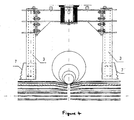
- fig. 1
- shows a log turning apparatus for a sawmill machine in a side view,
- fig. 2
- shows the log turning apparatus in a plan view before the log is turned,
- fig. 3
- shows the same as
fig. 1 , but the log has been turned by about 45° to the right, and - fig. 4
- shows a pivoting fork in an enlarged view.
- Referring to
figs. 1 ,2 and3 , logs are supplied along afeed conveyor 1 in a longitudinal direction. The spaces between logs can be as little as less than 0,5 m and the speeds can be as high as 200 m/min. The feed conveyor is furnished with a log gauge or some other measuring instrument capable of defining the butt/top sense of a log on the conveyor. - The logs are supplied by the conveyor onto the top of a log turner's
centering rolls 2. The fluted and centrally V-shaped rolls rotate in opposite directions, centering the logs according to the center of gravity and/or the midpoint. The rolls have a speed which is in a certain proportion to that of thefeed conveyor 1. - The turning moment and the sense of turning are determined by means of automatics. The automatics receives its data from a log gauge, a distance sensor and photocell, and activates an
overhead pivoting fork 3, which includes four pivoting arms at 90° relative to each other and at a distance very close to theroll 2. The pivoting arms have their ends provided with atooth system 7, preventing the log from slipping at the moment of turning. When thepivoting fork 3 begins its turning motion, the pivoting arms come to contact with the log and lift it first from a V-recess of thecentering rolls 2 to lie on top of the rolls. As the rolls are long and fluted, as well as rotating in senses opposite to each other, the log turns very quickly and effortlessly escorted by the pivoting arms. Thepivoting fork 3 may have a drive which is electromechanical or hydraulic and it only turns through 90° at a time towards a log and its speed is set according to that of thefeed conveyor 1. - While in the process of turning, the log falls down onto an
intermediate stopper 4. The purpose of this is to shorten the falling distance, to straighten a log possibly arriving in a misaligned position, to bring down a noise level, etc. Theintermediate stopper 4 can be used for collecting a single large or several small logs. Theintermediate stopper 4 is provided with noise abatement bars and its reciprocating action may be electromechanical or hydraulic. As the fall continues from the intermediate stopper, the logs are guided into the well of alog lift 5. The purpose of this is also to shorten the falling distance, to straighten a log possibly arriving in a misaligned position, to bring down a noise level, etc. The log lift's 5 well can be used for collecting a single large or several small logs. Thelog lift 5 has its bottom end provided with noise suppression and the lift delivers logs crosswise one or more at a time between the flights onto alateral conveyor 6 that follows. Thelateral conveyor 6 is used for collecting logs in the form of a long log carpet or small logs several on top of each other. - The
intermediate stopper 4 need not necessarily be a hook-shaped reciprocating element as it can be just as well a star-shaped wheel or another such element, which rotates always in the same direction and keeps dropping logs. - The angle of inclination for hoist brackets present at the ends of the pivoting
arms 3 need not be necessarily the same as the angle of a V-shaped recess in the middle of the centering rolls, but it can vary.
Claims (8)
- A log turning apparatus for a sawmill machine, which is supplied with logs one by one from a feed conveyor (1) and which log turning apparatus comprises a pivoting fork (3) capable of effecting a log turning motion to the right or left for bringing a desired end of the log, a buttltop, to always point the same way, an intermediate stopper (4) upon which the log, while turning, falls through an opening present below the pivoting fork (3), as well as a lateral conveyor (6), characterized in that, in connection with the pivoting fork (3) on either side of the fall opening, there are centering rolls (2) establishing a pair of centering rolls, and downstream of the intermediate stopper (4) the apparatus is provided with a log lift well and a log lift (5) which transfers the logs onto the lateral conveyor (6).
- A log turning apparatus as set forth in claim 1, characterized in that the intermediate stopper (4) consists of hook-like support members capable of being actuated between support and release positions by means of a connecting rod (8) or any other mechanical or hydraulic actuator enabling a reciprocating motion.
- A log turning apparatus as set forth in claims 1 and 2, characterized in that the intermediate stopper is a star-shaped wheel which rotates always in the same direction, dropping logs into the well of a log lift.
- A log turning apparatus as set forth in claim 2 or 3, characterized in that the intermediate stopper (4) has an inclined bottom, from which the log continues its downward passage by virtue of gravity by way of the well and the log lift (5) further onto a lateral conveyor (6).
- A log turning apparatus as set forth in any of the preceding claims, characterized in that the pivoting fork (3) has the ends of its pivoting arms fitted with hoist brackets whose angle of inclination is equal to the angle of a V-shaped recess present in the middle of the centering rolls.
- A log turning apparatus as set forth in claim 5, characterized in that the hoist brackets have a tooth system (7) along the edge thereof.
- A log turning apparatus as set forth in any of the preceding claims, characterized in that all four devices, the centering roll (2), the pivoting forks (3), the intermediate stopper (4), the well and the log lift (5), are controlled by automatics such that the devices are capable of being synchronized relative to each other.
- A log turning apparatus as set forth in claim 7, characterized in that said control automatics accelerates and decelates the logs maneuvering when needed.
Applications Claiming Priority (1)
| Application Number | Priority Date | Filing Date | Title |
|---|---|---|---|
| FI20051178A FI120643B (en) | 2005-11-18 | 2005-11-18 | Saw machine support turning equipment |
Publications (2)
| Publication Number | Publication Date |
|---|---|
| EP1787776A1 EP1787776A1 (en) | 2007-05-23 |
| EP1787776B1 true EP1787776B1 (en) | 2012-04-04 |
Family
ID=35458784
Family Applications (1)
| Application Number | Title | Priority Date | Filing Date |
|---|---|---|---|
| EP06124018A Active EP1787776B1 (en) | 2005-11-18 | 2006-11-14 | Log turning apparatus for a sawmill machine |
Country Status (3)
| Country | Link |
|---|---|
| EP (1) | EP1787776B1 (en) |
| AT (1) | ATE552082T1 (en) |
| FI (1) | FI120643B (en) |
Cited By (1)
| Publication number | Priority date | Publication date | Assignee | Title |
|---|---|---|---|---|
| CN108861490A (en) * | 2018-05-17 | 2018-11-23 | 漳州市炯辉机械有限公司 | A kind of high accurate identification round log rotary-cut assembly line |
Family Cites Families (5)
| Publication number | Priority date | Publication date | Assignee | Title |
|---|---|---|---|---|
| US3141482A (en) * | 1961-07-19 | 1964-07-21 | Sam K Arness | Core mill |
| FI49274C (en) * | 1971-05-12 | 1975-05-12 | Valo Antti T | Turning device for logs or the like |
| FI49951C (en) * | 1974-09-18 | 1975-11-10 | Valo Antti T | Turning device for logs and the like. |
| FI63553C (en) * | 1981-05-08 | 1983-07-11 | Taehkae Ab Oy | FOERFARANDE OCH ANORDNING FOER VAENDNING AV EN STOCK |
| SE526841C3 (en) * | 2002-10-11 | 2005-12-07 | Ingvar Persson I Skoevde Ab | Method and apparatus for distributing logs at an incoming transport path |
-
2005
- 2005-11-18 FI FI20051178A patent/FI120643B/en active IP Right Grant
-
2006
- 2006-11-14 AT AT06124018T patent/ATE552082T1/en active
- 2006-11-14 EP EP06124018A patent/EP1787776B1/en active Active
Cited By (2)
| Publication number | Priority date | Publication date | Assignee | Title |
|---|---|---|---|---|
| CN108861490A (en) * | 2018-05-17 | 2018-11-23 | 漳州市炯辉机械有限公司 | A kind of high accurate identification round log rotary-cut assembly line |
| CN108861490B (en) * | 2018-05-17 | 2020-08-25 | 漳州市炯辉机械有限公司 | High-precision round log rotary-cut assembly line |
Also Published As
| Publication number | Publication date |
|---|---|
| FI120643B (en) | 2010-01-15 |
| FI20051178A0 (en) | 2005-11-18 |
| FI20051178A (en) | 2007-05-19 |
| ATE552082T1 (en) | 2012-04-15 |
| EP1787776A1 (en) | 2007-05-23 |
Similar Documents
| Publication | Publication Date | Title |
|---|---|---|
| US5482140A (en) | Board inverter for use in lumber processing machine | |
| US7311192B2 (en) | Systems and methods for providing an improved timing conveyor | |
| KR0133355B1 (en) | Apparatus for supporting and restraining a log of paper during the cutting thereof by a log-saw | |
| EP2895409B1 (en) | Belt conveyor system, roller-engagement mechanism, and related method | |
| US4358009A (en) | Method and apparatus for sorting timber pieces | |
| US5363950A (en) | Lumber organizer | |
| US4316491A (en) | Automatic log processing apparatus and method | |
| NZ245317A (en) | Aligning and orientating fish on conveyor using tilting portion and chutes | |
| CA2136129A1 (en) | Machine for packing articles | |
| EP1216939A1 (en) | Device for conveying objects and including an accumulating buffer | |
| US4628781A (en) | Lumber mill system | |
| GB2125355A (en) | Apparatus for separating objects from a continuous row of objects | |
| AU2002353110B2 (en) | Selection system | |
| EP1787776B1 (en) | Log turning apparatus for a sawmill machine | |
| FI126275B (en) | Separator and method for separating pieces of wood | |
| CN209453715U (en) | A kind of saw material device | |
| CN208413124U (en) | A kind of automatic turnover machine | |
| SE458270B (en) | SETTING AND DEVICE TO CONTROL FILLING OF CONTAINERS | |
| WO2011074349A1 (en) | Rotational position determining method and rotational position determining system | |
| EP2019803A1 (en) | Sorting conveyor system | |
| US3981393A (en) | Log turning apparatus | |
| JPS6186039A (en) | Unit of long-sized wire rod and bar material | |
| US4669720A (en) | Ejector unit for machines for handling signatures and similar articles, particularly for signature-stacking machines | |
| JP2657370B2 (en) | Method and apparatus for peeling bent material | |
| US6152285A (en) | Conveyor arrangement |
Legal Events
| Date | Code | Title | Description |
|---|---|---|---|
| PUAI | Public reference made under article 153(3) epc to a published international application that has entered the european phase |
Free format text: ORIGINAL CODE: 0009012 |
|
| AK | Designated contracting states |
Kind code of ref document: A1 Designated state(s): AT BE BG CH CY CZ DE DK EE ES FI FR GB GR HU IE IS IT LI LT LU LV MC NL PL PT RO SE SI SK TR |
|
| AX | Request for extension of the european patent |
Extension state: AL BA HR MK YU |
|
| 17P | Request for examination filed |
Effective date: 20071123 |
|
| AKX | Designation fees paid |
Designated state(s): AT BE BG CH CY CZ DE DK EE ES FI FR GB GR HU IE IS IT LI LT LU LV MC NL PL PT RO SE SI SK TR |
|
| 17Q | First examination report despatched |
Effective date: 20080204 |
|
| GRAP | Despatch of communication of intention to grant a patent |
Free format text: ORIGINAL CODE: EPIDOSNIGR1 |
|
| GRAS | Grant fee paid |
Free format text: ORIGINAL CODE: EPIDOSNIGR3 |
|
| GRAA | (expected) grant |
Free format text: ORIGINAL CODE: 0009210 |
|
| AK | Designated contracting states |
Kind code of ref document: B1 Designated state(s): AT BE BG CH CY CZ DE DK EE ES FI FR GB GR HU IE IS IT LI LT LU LV MC NL PL PT RO SE SI SK TR |
|
| REG | Reference to a national code |
Ref country code: GB Ref legal event code: FG4D |
|
| REG | Reference to a national code |
Ref country code: CH Ref legal event code: EP |
|
| REG | Reference to a national code |
Ref country code: AT Ref legal event code: REF Ref document number: 552082 Country of ref document: AT Kind code of ref document: T Effective date: 20120415 |
|
| REG | Reference to a national code |
Ref country code: IE Ref legal event code: FG4D |
|
| REG | Reference to a national code |
Ref country code: DE Ref legal event code: R096 Ref document number: 602006028583 Country of ref document: DE Effective date: 20120531 |
|
| REG | Reference to a national code |
Ref country code: RO Ref legal event code: EPE |
|
| REG | Reference to a national code |
Ref country code: NL Ref legal event code: VDEP Effective date: 20120404 |
|
| REG | Reference to a national code |
Ref country code: SE Ref legal event code: TRGR |
|
| PG25 | Lapsed in a contracting state [announced via postgrant information from national office to epo] |
Ref country code: IS Free format text: LAPSE BECAUSE OF FAILURE TO SUBMIT A TRANSLATION OF THE DESCRIPTION OR TO PAY THE FEE WITHIN THE PRESCRIBED TIME-LIMIT Effective date: 20120804 Ref country code: FI Free format text: LAPSE BECAUSE OF FAILURE TO SUBMIT A TRANSLATION OF THE DESCRIPTION OR TO PAY THE FEE WITHIN THE PRESCRIBED TIME-LIMIT Effective date: 20120404 Ref country code: PL Free format text: LAPSE BECAUSE OF FAILURE TO SUBMIT A TRANSLATION OF THE DESCRIPTION OR TO PAY THE FEE WITHIN THE PRESCRIBED TIME-LIMIT Effective date: 20120404 Ref country code: CY Free format text: LAPSE BECAUSE OF FAILURE TO SUBMIT A TRANSLATION OF THE DESCRIPTION OR TO PAY THE FEE WITHIN THE PRESCRIBED TIME-LIMIT Effective date: 20120404 Ref country code: SI Free format text: LAPSE BECAUSE OF FAILURE TO SUBMIT A TRANSLATION OF THE DESCRIPTION OR TO PAY THE FEE WITHIN THE PRESCRIBED TIME-LIMIT Effective date: 20120404 |
|
| PG25 | Lapsed in a contracting state [announced via postgrant information from national office to epo] |
Ref country code: GR Free format text: LAPSE BECAUSE OF FAILURE TO SUBMIT A TRANSLATION OF THE DESCRIPTION OR TO PAY THE FEE WITHIN THE PRESCRIBED TIME-LIMIT Effective date: 20120705 Ref country code: PT Free format text: LAPSE BECAUSE OF FAILURE TO SUBMIT A TRANSLATION OF THE DESCRIPTION OR TO PAY THE FEE WITHIN THE PRESCRIBED TIME-LIMIT Effective date: 20120806 |
|
| PG25 | Lapsed in a contracting state [announced via postgrant information from national office to epo] |
Ref country code: BE Free format text: LAPSE BECAUSE OF FAILURE TO SUBMIT A TRANSLATION OF THE DESCRIPTION OR TO PAY THE FEE WITHIN THE PRESCRIBED TIME-LIMIT Effective date: 20120404 |
|
| PG25 | Lapsed in a contracting state [announced via postgrant information from national office to epo] |
Ref country code: NL Free format text: LAPSE BECAUSE OF FAILURE TO SUBMIT A TRANSLATION OF THE DESCRIPTION OR TO PAY THE FEE WITHIN THE PRESCRIBED TIME-LIMIT Effective date: 20120404 Ref country code: DK Free format text: LAPSE BECAUSE OF FAILURE TO SUBMIT A TRANSLATION OF THE DESCRIPTION OR TO PAY THE FEE WITHIN THE PRESCRIBED TIME-LIMIT Effective date: 20120404 Ref country code: SK Free format text: LAPSE BECAUSE OF FAILURE TO SUBMIT A TRANSLATION OF THE DESCRIPTION OR TO PAY THE FEE WITHIN THE PRESCRIBED TIME-LIMIT Effective date: 20120404 |
|
| PLBE | No opposition filed within time limit |
Free format text: ORIGINAL CODE: 0009261 |
|
| STAA | Information on the status of an ep patent application or granted ep patent |
Free format text: STATUS: NO OPPOSITION FILED WITHIN TIME LIMIT |
|
| REG | Reference to a national code |
Ref country code: EE Ref legal event code: FG4A Ref document number: E007351 Country of ref document: EE Effective date: 20120704 |
|
| PG25 | Lapsed in a contracting state [announced via postgrant information from national office to epo] |
Ref country code: IT Free format text: LAPSE BECAUSE OF FAILURE TO SUBMIT A TRANSLATION OF THE DESCRIPTION OR TO PAY THE FEE WITHIN THE PRESCRIBED TIME-LIMIT Effective date: 20120404 |
|
| 26N | No opposition filed |
Effective date: 20130107 |
|
| PG25 | Lapsed in a contracting state [announced via postgrant information from national office to epo] |
Ref country code: ES Free format text: LAPSE BECAUSE OF FAILURE TO SUBMIT A TRANSLATION OF THE DESCRIPTION OR TO PAY THE FEE WITHIN THE PRESCRIBED TIME-LIMIT Effective date: 20120715 |
|
| REG | Reference to a national code |
Ref country code: DE Ref legal event code: R097 Ref document number: 602006028583 Country of ref document: DE Effective date: 20130107 |
|
| REG | Reference to a national code |
Ref country code: CH Ref legal event code: PL |
|
| PG25 | Lapsed in a contracting state [announced via postgrant information from national office to epo] |
Ref country code: LI Free format text: LAPSE BECAUSE OF NON-PAYMENT OF DUE FEES Effective date: 20121130 Ref country code: BG Free format text: LAPSE BECAUSE OF FAILURE TO SUBMIT A TRANSLATION OF THE DESCRIPTION OR TO PAY THE FEE WITHIN THE PRESCRIBED TIME-LIMIT Effective date: 20120704 Ref country code: CH Free format text: LAPSE BECAUSE OF NON-PAYMENT OF DUE FEES Effective date: 20121130 |
|
| PG25 | Lapsed in a contracting state [announced via postgrant information from national office to epo] |
Ref country code: MC Free format text: LAPSE BECAUSE OF NON-PAYMENT OF DUE FEES Effective date: 20121130 Ref country code: TR Free format text: LAPSE BECAUSE OF FAILURE TO SUBMIT A TRANSLATION OF THE DESCRIPTION OR TO PAY THE FEE WITHIN THE PRESCRIBED TIME-LIMIT Effective date: 20120404 |
|
| PG25 | Lapsed in a contracting state [announced via postgrant information from national office to epo] |
Ref country code: LU Free format text: LAPSE BECAUSE OF NON-PAYMENT OF DUE FEES Effective date: 20121114 |
|
| PG25 | Lapsed in a contracting state [announced via postgrant information from national office to epo] |
Ref country code: HU Free format text: LAPSE BECAUSE OF FAILURE TO SUBMIT A TRANSLATION OF THE DESCRIPTION OR TO PAY THE FEE WITHIN THE PRESCRIBED TIME-LIMIT Effective date: 20061114 |
|
| PGFP | Annual fee paid to national office [announced via postgrant information from national office to epo] |
Ref country code: RO Payment date: 20141104 Year of fee payment: 9 Ref country code: GB Payment date: 20141124 Year of fee payment: 9 Ref country code: LT Payment date: 20141103 Year of fee payment: 9 Ref country code: IE Payment date: 20141117 Year of fee payment: 9 Ref country code: EE Payment date: 20141126 Year of fee payment: 9 Ref country code: CZ Payment date: 20141031 Year of fee payment: 9 |
|
| PGFP | Annual fee paid to national office [announced via postgrant information from national office to epo] |
Ref country code: AT Payment date: 20141124 Year of fee payment: 9 Ref country code: LV Payment date: 20141113 Year of fee payment: 9 Ref country code: FR Payment date: 20141201 Year of fee payment: 9 |
|
| REG | Reference to a national code |
Ref country code: LT Ref legal event code: MM4D Effective date: 20151114 |
|
| REG | Reference to a national code |
Ref country code: AT Ref legal event code: MM01 Ref document number: 552082 Country of ref document: AT Kind code of ref document: T Effective date: 20151114 Ref country code: EE Ref legal event code: MM4A Ref document number: E007351 Country of ref document: EE Effective date: 20151130 |
|
| GBPC | Gb: european patent ceased through non-payment of renewal fee |
Effective date: 20151114 |
|
| PG25 | Lapsed in a contracting state [announced via postgrant information from national office to epo] |
Ref country code: CZ Free format text: LAPSE BECAUSE OF NON-PAYMENT OF DUE FEES Effective date: 20151114 |
|
| REG | Reference to a national code |
Ref country code: IE Ref legal event code: MM4A |
|
| REG | Reference to a national code |
Ref country code: FR Ref legal event code: ST Effective date: 20160729 |
|
| PG25 | Lapsed in a contracting state [announced via postgrant information from national office to epo] |
Ref country code: LT Free format text: LAPSE BECAUSE OF NON-PAYMENT OF DUE FEES Effective date: 20151114 Ref country code: LV Free format text: LAPSE BECAUSE OF NON-PAYMENT OF DUE FEES Effective date: 20151114 Ref country code: RO Free format text: LAPSE BECAUSE OF NON-PAYMENT OF DUE FEES Effective date: 20151114 Ref country code: AT Free format text: LAPSE BECAUSE OF NON-PAYMENT OF DUE FEES Effective date: 20151114 Ref country code: EE Free format text: LAPSE BECAUSE OF NON-PAYMENT OF DUE FEES Effective date: 20151130 |
|
| PG25 | Lapsed in a contracting state [announced via postgrant information from national office to epo] |
Ref country code: IE Free format text: LAPSE BECAUSE OF NON-PAYMENT OF DUE FEES Effective date: 20151114 Ref country code: GB Free format text: LAPSE BECAUSE OF NON-PAYMENT OF DUE FEES Effective date: 20151114 |
|
| PG25 | Lapsed in a contracting state [announced via postgrant information from national office to epo] |
Ref country code: FR Free format text: LAPSE BECAUSE OF NON-PAYMENT OF DUE FEES Effective date: 20151130 |
|
| PGFP | Annual fee paid to national office [announced via postgrant information from national office to epo] |
Ref country code: SE Payment date: 20221116 Year of fee payment: 17 Ref country code: DE Payment date: 20221117 Year of fee payment: 17 |