EP1787352B1 - Broadcast signal waveguide - Google Patents
Broadcast signal waveguide Download PDFInfo
- Publication number
- EP1787352B1 EP1787352B1 EP05786132A EP05786132A EP1787352B1 EP 1787352 B1 EP1787352 B1 EP 1787352B1 EP 05786132 A EP05786132 A EP 05786132A EP 05786132 A EP05786132 A EP 05786132A EP 1787352 B1 EP1787352 B1 EP 1787352B1
- Authority
- EP
- European Patent Office
- Prior art keywords
- waveguide
- components
- same
- polarisation
- circular
- Prior art date
- Legal status (The legal status is an assumption and is not a legal conclusion. Google has not performed a legal analysis and makes no representation as to the accuracy of the status listed.)
- Expired - Lifetime
Links
Images

Classifications
-
- H—ELECTRICITY
- H01—ELECTRIC ELEMENTS
- H01P—WAVEGUIDES; RESONATORS, LINES, OR OTHER DEVICES OF THE WAVEGUIDE TYPE
- H01P1/00—Auxiliary devices
- H01P1/16—Auxiliary devices for mode selection, e.g. mode suppression or mode promotion; for mode conversion
- H01P1/161—Auxiliary devices for mode selection, e.g. mode suppression or mode promotion; for mode conversion sustaining two independent orthogonal modes, e.g. orthomode transducer
Definitions
- the invention to which this application relates is a waveguide apparatus for use in the reception of radio frequency signals of first and second polarity types such as circular and linear polarity.
- waveguide apparatus to receive two different forms of broadcast signals
- one known apparatus is called an OMT (Ortho Mode Transducer) waveguide.
- OMT Organic Mode Transducer
- this waveguide there is provided an input into which all the received signals pass to go along a channel.
- a signal deflector which causes a portion of the received signals, of a first polarity type, to be deflected in a direction perpendicular to the said channel and be directed in said second direction to an outlet along a second channel.
- the remainder of the frequency signals pass the deflector and move towards the outlet of the first channel such that when the first and second sets of radio frequency signals leave the OMT waveguide, they do so in first and second, perpendicular directions.
- this form of waveguide can be of use in particular instances, as it provides isolation between the emitted first and second polarity types the same is not of use when it is required that the first and second set of radio frequency signals are matched in phase which can also be referred to as "matched in phase", as the first and second set of signals are emitted at different locations and in different directions, having passed along different distances and as a result when the same are emitted they are not coherent i.e they are not balanced in terms of phase. This can cause the subsequent processing of the signals to be disturbed and unacceptable.
- EP0419892 discloses a polarisation filter which achieves phase symmetry at four output ports by providing transmission paths between the inlet and outlets of the same length.
- the aim of the present invention is to provide a waveguide apparatus which allows for the problem of separation of first and second sets of received signals in a manner so as to allow the first and second sets to be subsequently processed separately and to do so in a manner which allows the same to be matched in phase where the same are emitted from the waveguide, and hence allow the same to be processed subsequently in the same phase.
- This problem is solved by a waveguide apparatus according to claim 1.
- the channels each have the same cross sectional shape, preferably square, although in principle these could be of different shapes.
- the first channel interfaces with a data transmission receiving feedhorn or antenna which receives a first (linear polarity) and second (circular polarity) signal types, typically from a satellite, although terrestrial, or coaxial data communication systems could be interfaced with the waveguide.
- a data transmission receiving feedhorn or antenna which receives a first (linear polarity) and second (circular polarity) signal types, typically from a satellite, although terrestrial, or coaxial data communication systems could be interfaced with the waveguide.
- the first channel of the waveguide can support both Vertical (V) and Horizontal (H) components of the linear polarisation signal type and Left and Right hand components of the circular polarisation signal type.
- the apertures in the first channel are provided, one in each orthogonal plane; to couple the signal types into the adjacent second and third channels.
- the second and third channels carry one of the two orthogonal components of the incoming signal.
- the two orthogonal signal components will be pure vertical in one of the second or third channels and pure horizontal in the other of the second or third channels.
- the two orthogonal signals represent orthogonal components of both left and right hand polarisations, so that the second and third channels each carry half of the left hand circular polarisation and half of the right hand circular polarisation simultaneously.
- the orthogonal components As the paths of the two orthogonal signal components are of substantially the same length, when the components leave the waveguide outlets, typically on waveguide probes at a PCB interface, the orthogonal components have substantially the same phase relationship to each other as when they entered the first channel. This is of primary importance for Circular Polarity signal types.
- the signal type components upon leaving the first channel through their respective apertures move in an initial direction which is substantially perpendicular to the direction of movement along the first channel and then are further deflected by the walls of the respective channels to move along their respective channels towards outlets, said outlets lying in the same plane.
- the components move along the respective second and third channels along a path which is parallel with the direction of movement along the first channel.
- the said first and second components of the received signal are separated thereby allowing subsequent processing of the same to be achieved in isolation and, at the same time, due to the configuration of the first channel and parallel channels along which the deflected radio frequency signals pass and the provision of the outlets of said further channels in the same plane, the separated signals which are emitted from the waveguide apparatus are matched in phase as the length of the paths which the signal types follow is substantially the same.
- all of the channels are defined within a housing, typically of a metal or metal alloy.
- each of the channels is of a common cross sectional area and cross sectional shape. In one embodiment, the cross sectional shape of each channel is square.
- the first channel is linear and has an outlet, and said outlet can be masked but typically, it does not require to be masked as the first and second deflection means cause all of the received signal type components to be deflected from and out of the first channel and into the respective second or third channels prior to reaching the outlet.
- the apertures in the first channel adjacent each of the deflection means are rectangular in shape, with a first aperture formed on a first side of the channel and a second aperture formed on another side of the channel.
- the first and second deflection means are circular cross sectional pins which are mounted in the first channel and which act as a short circuit for a particular type of signals and hence deflect the same into the aperture formed in the wall of the first channel adjacent thereto.
- the format of the components is dependent upon the polarity of the received data signals.
- linear polarity and circular polarity signal types are transmitted from a satellite.
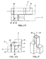
- FIG. 1a to d there is illustrated a waveguide apparatus in accordance with the invention which can be used to allow the separation and subsequent processing in an effective manner, of components of received circular and/or linear polarity signals or types typically via a satellite antenna.
- This thereby allows the waveguide and the receiving apparatus generally to be used to receive both polarity signal types whereas conventionally the receiving apparatus would only be able to receive circular or linear polarity signal types.
- first and second sets of signals will increasingly be transmitted to receiving apparatus with circular polarity or linear polarity to allow a greater radio frequency range to be used and hence allow a greater choice to users of the receiving apparatus in terms of television and/or radio channels which can be selected.
- it is subsequently required to process the said circular and linear polarity signals with the same being matched in phase and the waveguide as described herein allows this to occur.
- the waveguide apparatus 2 has an inlet 4 into which all received radio frequency signals pass having been received from the feedhorn or antenna with which the inlet interfaces.
- the inlet 4 leads into a first channel 6 which has an outlet at the opposite end 8 but through which no signals pass as will be illustrated herein.
- the first channel 6 is linear and has a longitudinal axis 10.
- a first deflector pin 11 Adjacent the said deflector pin and on a first wall 12 of the first channel is provided an aperture 14.
- the deflector pin acts to deflect a first type or component of the received signals out of the first channel 6 and through the aperture leading into a second channel 16.
- Another type or component of the received radio frequency signals move along the first channel until they reach the second deflector pin 18.
- This deflector pin 18 causes the second type or component of the received signal to pass through an aperture 20 in the side wall 22 of the first channel and into a third channel 24.
- the second and third channels, 16, 24 both include a section 28, 32 respectively which has a longitudinal axis 30 which is parallel to the longitudinal axis of the first channel as shown.
- the sections 28, 32 allow the passage of the first and second types or components of the received signals along said second and third channels in a guided manner.
- the outlets 34, 36 of the channels 16, 24 are provided at a common plane 40 as shown and from there the first and second types or components of the received signals are passed, matched in phase for further processing by probes 42, 44 separately as required.
- the first and second components of the received signals pass along a path of the same distance and are emitted via outlets 34,36 in a common plane, so the first and second components are matched in phase as well as isolated.
- Figure 2 illustrates in schematic manner, the waveguide apparatus in accordance with the invention and the manner in which the first and second types or components of received signals are directed to pass through the waveguide.
- the arrows 50 in solid lines, indicate the passage of a first type or component of the received signal and the arrows 52 in broken lines indicate the passage of the second type or component of the received signals.
- the waveguide structure comprises 3 adjacent square channels, 6, 16, 24.
- the first channel 6 will generally interface to a feedhorn or antenna (not shown) which can be mounted on an external wall of a building to receive data signals of either or both of linear or circular polarity signals from typically a satellite but it could also could be terrestrial or even interfaced to coaxial connectors.
- the waveguide can support both V and H linear polarisations and Left and Right hand circular polarisations of the received data signals and therefore allows the processing of both via one set of receiving apparatus thereby allowing the widening of the radio frequency of data signals which can be received and processed.
- the channel has two apertures 14, 20 along its length, one in each orthogonal plane. These apertures couple the received signal components into one or other of the adjacent two channels 16,24. Each of the adjacent channels carries one of the two orthogonal components of the received signal type.
- the two orthogonal components will be a pure vertical component which are deflected into channel 16 and a pure horizontal components deflected into the channel 24.
- the orthogonal components represent left and right hand circular polarisations so in effect the first component which passes along channel 16 includes half of the left hand circular polarisation and half of the right hand circular polarisation and the other channel 24 carries the other halves of the left and right hand circular polarisations simultaneously.
- the two orthogonal components are extracted from the adjacent waveguide ends, typically on waveguide probes at the PCB interface, they have almost the same phase relationship to each other as when they entered the main waveguide; which is primarily of importance for circular polarity signals. Additionally, the waveguide is frequency dispersive and so any dispersion effects are effectively cancelled out due to the effective waveguide paths of the orthogonal components being nearly identical. This allows for near perfect extraction of the circularly polarised signals with very low cross-polar interference. In one embodiment the extraction can be performed using a phase shifting network, most typically a 3dB hybrid or similar.
- a waveguide apparatus which provides for the effective separation of first and second types or components of received radio frequency signals and furthermore, allows for the emission of the separated radio frequency signals in a matched in phase manner.
Landscapes
- Waveguide Aerials (AREA)
- Variable-Direction Aerials And Aerial Arrays (AREA)
- Input Circuits Of Receivers And Coupling Of Receivers And Audio Equipment (AREA)
- Diaphragms For Electromechanical Transducers (AREA)
- Optical Communication System (AREA)
Abstract
Description
- The invention to which this application relates is a waveguide apparatus for use in the reception of radio frequency signals of first and second polarity types such as circular and linear polarity.
- The provision of waveguide apparatus to receive two different forms of broadcast signals is known and one known apparatus is called an OMT (Ortho Mode Transducer) waveguide. In this waveguide, there is provided an input into which all the received signals pass to go along a channel. Provided intermediate the input and output of said channel, there is provided a signal deflector which causes a portion of the received signals, of a first polarity type, to be deflected in a direction perpendicular to the said channel and be directed in said second direction to an outlet along a second channel. The remainder of the frequency signals, typically the signals of the second polarity type, pass the deflector and move towards the outlet of the first channel such that when the first and second sets of radio frequency signals leave the OMT waveguide, they do so in first and second, perpendicular directions. While this form of waveguide can be of use in particular instances, as it provides isolation between the emitted first and second polarity types the same is not of use when it is required that the first and second set of radio frequency signals are matched in phase which can also be referred to as "matched in phase", as the first and second set of signals are emitted at different locations and in different directions, having passed along different distances and as a result when the same are emitted they are not coherent i.e they are not balanced in terms of phase. This can cause the subsequent processing of the signals to be disturbed and unacceptable.
- The document by V.A Stuzhin et al: "Equipment for multiplexing the waveguide channels of radio-relay systems" Telecommunications and Radio Engineering, vol. 29/30, No. 3, March 1975, page 32-34, XP002356277, as the closest prior art document, discloses a waveguide apparatus which deflects polarisation components of received data along different passages to perpendicularly placed outlets, but does so in a manner such that the components are generally not in the same phase.
-
EP0419892 discloses a polarisation filter which achieves phase symmetry at four output ports by providing transmission paths between the inlet and outlets of the same length. - The document Patent Abstracts of Japan vol. 017, No. 466, 25th August 1993, &
JP-A-05-110302 - The aim of the present invention is to provide a waveguide apparatus which allows for the problem of separation of first and second sets of received signals in a manner so as to allow the first and second sets to be subsequently processed separately and to do so in a manner which allows the same to be matched in phase where the same are emitted from the waveguide, and hence allow the same to be processed subsequently in the same phase. This problem is solved by a waveguide apparatus according to claim 1.
- Typically the distances travelled by the said components from entering the waveguide to leaving the same at their respective outlets are substantially the same.
- In a preferred embodiment the channels each have the same cross sectional shape, preferably square, although in principle these could be of different shapes.
- Typically the first channel interfaces with a data transmission receiving feedhorn or antenna which receives a first (linear polarity) and second (circular polarity) signal types, typically from a satellite, although terrestrial, or coaxial data communication systems could be interfaced with the waveguide.
- Typically the first channel of the waveguide can support both Vertical (V) and Horizontal (H) components of the linear polarisation signal type and Left and Right hand components of the circular polarisation signal type.
- Typically the apertures in the first channel are provided, one in each orthogonal plane; to couple the signal types into the adjacent second and third channels. Typically the second and third channels carry one of the two orthogonal components of the incoming signal.
- In the case of linear polarisation signal types the two orthogonal signal components will be pure vertical in one of the second or third channels and pure horizontal in the other of the second or third channels. In the case of circular polarisation the two orthogonal signals represent orthogonal components of both left and right hand polarisations, so that the second and third channels each carry half of the left hand circular polarisation and half of the right hand circular polarisation simultaneously.
- As the paths of the two orthogonal signal components are of substantially the same length, when the components leave the waveguide outlets, typically on waveguide probes at a PCB interface, the orthogonal components have substantially the same phase relationship to each other as when they entered the first channel. This is of primary importance for Circular Polarity signal types.
- In one embodiment the signal type components upon leaving the first channel through their respective apertures move in an initial direction which is substantially perpendicular to the direction of movement along the first channel and then are further deflected by the walls of the respective channels to move along their respective channels towards outlets, said outlets lying in the same plane.
- The components move along the respective second and third channels along a path which is parallel with the direction of movement along the first channel.
- Thus, in accordance with the invention, the said first and second components of the received signal are separated thereby allowing subsequent processing of the same to be achieved in isolation and, at the same time, due to the configuration of the first channel and parallel channels along which the deflected radio frequency signals pass and the provision of the outlets of said further channels in the same plane, the separated signals which are emitted from the waveguide apparatus are matched in phase as the length of the paths which the signal types follow is substantially the same.
- In one embodiment, all of the channels are defined within a housing, typically of a metal or metal alloy.
- In one embodiment, each of the channels is of a common cross sectional area and cross sectional shape. In one embodiment, the cross sectional shape of each channel is square.
- In one embodiment, the first channel is linear and has an outlet, and said outlet can be masked but typically, it does not require to be masked as the first and second deflection means cause all of the received signal type components to be deflected from and out of the first channel and into the respective second or third channels prior to reaching the outlet.
- In one embodiment, the apertures in the first channel adjacent each of the deflection means are rectangular in shape, with a first aperture formed on a first side of the channel and a second aperture formed on another side of the channel.
- In one embodiment, the first and second deflection means are circular cross sectional pins which are mounted in the first channel and which act as a short circuit for a particular type of signals and hence deflect the same into the aperture formed in the wall of the first channel adjacent thereto.
- Typically the format of the components is dependent upon the polarity of the received data signals.
- Typically the linear polarity and circular polarity signal types are transmitted from a satellite.
- A specific embodiment of the invention is now described with reference to the accompanying drawings, wherein:-
-
Figures 1a to d illustrate a waveguide apparatus in accordance with one embodiment of the invention; and -
Figure 2 illustrates the passage of the first and second sets of signals as they pass through the waveguide apparatus ofFigures 1a to d. - Referring firstly to
Figures 1a to d , there is illustrated a waveguide apparatus in accordance with the invention which can be used to allow the separation and subsequent processing in an effective manner, of components of received circular and/or linear polarity signals or types typically via a satellite antenna. This thereby allows the waveguide and the receiving apparatus generally to be used to receive both polarity signal types whereas conventionally the receiving apparatus would only be able to receive circular or linear polarity signal types. - It is envisaged that first and second sets of signals will increasingly be transmitted to receiving apparatus with circular polarity or linear polarity to allow a greater radio frequency range to be used and hence allow a greater choice to users of the receiving apparatus in terms of television and/or radio channels which can be selected. As a result of this it is subsequently required to process the said circular and linear polarity signals with the same being matched in phase and the waveguide as described herein allows this to occur.
- The
waveguide apparatus 2 has aninlet 4 into which all received radio frequency signals pass having been received from the feedhorn or antenna with which the inlet interfaces. Theinlet 4 leads into afirst channel 6 which has an outlet at theopposite end 8 but through which no signals pass as will be illustrated herein. - The
first channel 6 is linear and has alongitudinal axis 10. Provided at a first intermediate location on the first channel, is afirst deflector pin 11. Adjacent the said deflector pin and on afirst wall 12 of the first channel is provided anaperture 14. The deflector pin acts to deflect a first type or component of the received signals out of thefirst channel 6 and through the aperture leading into asecond channel 16. Another type or component of the received radio frequency signals move along the first channel until they reach thesecond deflector pin 18. Thisdeflector pin 18 causes the second type or component of the received signal to pass through anaperture 20 in theside wall 22 of the first channel and into athird channel 24. - As a result, in this example, no or only a few signals will still be left in the first channel downstream of the
second deflector pin 18. The second and third channels, 16, 24 both include asection longitudinal axis 30 which is parallel to the longitudinal axis of the first channel as shown. Thesections outlets channels common plane 40 as shown and from there the first and second types or components of the received signals are passed, matched in phase for further processing byprobes - As, in each case, the first and second components of the received signals pass along a path of the same distance and are emitted via
outlets -
Figure 2 illustrates in schematic manner, the waveguide apparatus in accordance with the invention and the manner in which the first and second types or components of received signals are directed to pass through the waveguide. Thearrows 50, in solid lines, indicate the passage of a first type or component of the received signal and thearrows 52 in broken lines indicate the passage of the second type or component of the received signals. - The cross sectional shape and size of the channels along which the signal types or components is preferably nominally the same to maintain the matching phase of the signal types. Furthermore the outlets of the channels are preferably provided in the same plane so that the distance to the outlets is the same.
- Thus in accordance with a practical implementation of the invention, the waveguide structure comprises 3 adjacent square channels, 6, 16, 24. The
first channel 6 will generally interface to a feedhorn or antenna (not shown) which can be mounted on an external wall of a building to receive data signals of either or both of linear or circular polarity signals from typically a satellite but it could also could be terrestrial or even interfaced to coaxial connectors. - The waveguide can support both V and H linear polarisations and Left and Right hand circular polarisations of the received data signals and therefore allows the processing of both via one set of receiving apparatus thereby allowing the widening of the radio frequency of data signals which can be received and processed.
- The channel has two
apertures channels - For example, in the case of linear polarity received signals these two orthogonal components will be a pure vertical component which are deflected into
channel 16 and a pure horizontal components deflected into thechannel 24. In the case of circular polarisation the orthogonal components represent left and right hand circular polarisations so in effect the first component which passes alongchannel 16 includes half of the left hand circular polarisation and half of the right hand circular polarisation and theother channel 24 carries the other halves of the left and right hand circular polarisations simultaneously. - As the two paths along which the components pass are substantially of identical length, when the two orthogonal components are extracted from the adjacent waveguide ends, typically on waveguide probes at the PCB interface, they have almost the same phase relationship to each other as when they entered the main waveguide; which is primarily of importance for circular polarity signals. Additionally, the waveguide is frequency dispersive and so any dispersion effects are effectively cancelled out due to the effective waveguide paths of the orthogonal components being nearly identical. This allows for near perfect extraction of the circularly polarised signals with very low cross-polar interference. In one embodiment the extraction can be performed using a phase shifting network, most typically a 3dB hybrid or similar.
- There is therefore provided in accordance with the invention a waveguide apparatus which provides for the effective separation of first and second types or components of received radio frequency signals and furthermore, allows for the emission of the separated radio frequency signals in a matched in phase manner.
Claims (19)
- Waveguide apparatus (2) for use with received data, said apparatus including an inlet (4) into a first waveguide (6) into which received signals of at least one polarisation type pass, said first waveguide (6) having located therein a first deflection means (11), which causes one component of said polarisation type to be deflected to leave said first waveguide (6), through an aperture (14) in a wall (12, 22) of the first waveguide (6), into a second waveguide (16), having an outlet (34), whereas a second deflection means (18), located in the first waveguide (6), causes one further component of said polarisation type to be deflected to leave said first waveguide (6), through a further aperture (20) in the wall (12, 22) of said first waveguide (6), into a third waveguide (24), having a further outlet (36), characterised in that the phase relationship of the polarisation components at the outlets (34, 36) of the second (16) and third (24) waveguide is the same as the phase relationship of these polarisation components at the inlet (4) of the first waveguide (6), and the three waveguides (6, 16, 24) are parallel.
- Apparatus according to claim 1 wherein the distances travelled by the said components from the inlet (4) of the first waveguide (6) to the respective outlets (34, 36) are the same.
- Apparatus according to claim 1 characterised in that the waveguides (6, 16, 24) each have the same cross sectional shape.
- Apparatus according to claim 1 characterised in that the first waveguide (6) interfaces with a data transmission receiving feedhorn or antenna.
- Apparatus according to claim 1 characterised in that the first waveguide (6) can support both Vertical (V) and Horizontal (H) components of a linear polarity type and Left and Right hand components of a circular polarity type.
- Apparatus according to claim 1 characterised in that the apertures (14, 20) in the first waveguide (6) are provided, one in each orthogonal plane.
- Apparatus according to claim 1 characterised in that the second and third waveguides (16, 24) each carry one of the two orthogonal components of the incoming signal type.
- Apparatus according to claim 7 characterised in that in the case of a received linear polarity type, one of the two orthogonal components thereof, which enters one of the second or third waveguides (16, 24), is horizontal, and the other component, which enters the other of the second or third waveguides (16, 24), is vertical.
- Apparatus according to claim 1 characterised in that in the case of a received circular polarity signal type a first orthogonal signal component is half of the circular polarisation, , and the other orthogonal signal component is formed by the other halve of the circular polarisation.
- Apparatus according to any of the preceding claims characterised in that the paths of the two orthogonal signal components are of substantially the same length and when the components leave the second and third waveguide outlets (34, 36) the components have substantially the same phase relationship to each other as when they entered the first waveguide (6).
- Apparatus according to claim 1 characterised in that the first and/or second components upon leaving the first waveguide (6) through their respective apertures (14, 20), move in an initial direction which is substantially perpendicular to the direction of movement along the firsrt waveguide (6).
- Apparatus according to claim 1 characterised in that the outlets (34, 36) lie in the same plane.
- Apparatus according to claim 1 characterised in that the said components are separated at the outlets (34, 36) and thereby allow subsequent processing of the components to be achieved in isolation.
- Apparatus according to any preceding claim characterised in that all of the waveguides (6, 16, 24) are formed within a waveguide housing formed of a metal or metal alloy.
- Apparatus according to claim 1 characterised in that the first waveguide (6) is linear in shape.
- Apparatus according to claim 1 characterised in the first and second deflection means (11, 18) are circular cross sectional pins mounted in the first waveguide (6) and which protrude, at least partially into said first waveguide (6).
- Apparatus according to claim 1 characterised in that the said first and second deflection means (11, 18) are provided in the first waveguide (6) to lie with their longitudinal axis perpendicular to each other.
- Apparatus according to claim 1 characterised in that the first and second deflection means (11, 18) are adjustable so as to allow adjustment of the extent to which the same extend inwardly of the said first waveguide (6).
- Apparatus according to claim 1 characterised in that the linear polarity and circular polarity signal types are received from a satellite.
Applications Claiming Priority (2)
| Application Number | Priority Date | Filing Date | Title |
|---|---|---|---|
| GBGB0419884.2A GB0419884D0 (en) | 2004-09-08 | 2004-09-08 | Broadcast signal waveguide |
| PCT/GB2005/003463 WO2006027588A1 (en) | 2004-09-08 | 2005-09-08 | Broadcast signal waveguide |
Publications (2)
| Publication Number | Publication Date |
|---|---|
| EP1787352A1 EP1787352A1 (en) | 2007-05-23 |
| EP1787352B1 true EP1787352B1 (en) | 2008-12-03 |
Family
ID=33186631
Family Applications (1)
| Application Number | Title | Priority Date | Filing Date |
|---|---|---|---|
| EP05786132A Expired - Lifetime EP1787352B1 (en) | 2004-09-08 | 2005-09-08 | Broadcast signal waveguide |
Country Status (6)
| Country | Link |
|---|---|
| US (1) | US7804381B2 (en) |
| EP (1) | EP1787352B1 (en) |
| AT (1) | ATE416491T1 (en) |
| DE (1) | DE602005011459D1 (en) |
| GB (1) | GB0419884D0 (en) |
| WO (1) | WO2006027588A1 (en) |
Families Citing this family (3)
| Publication number | Priority date | Publication date | Assignee | Title |
|---|---|---|---|---|
| GB0508034D0 (en) * | 2005-04-21 | 2005-05-25 | Invacom Ltd | Multi polarity format data receiving apparatus |
| JP5089766B2 (en) * | 2008-03-25 | 2012-12-05 | 三菱電機株式会社 | Waveguide power distributor and manufacturing method thereof |
| GB201416915D0 (en) * | 2014-09-25 | 2014-11-12 | Global Invacom Ltd | Apparatus for selected provision of linear and/or circular polarity signals |
Family Cites Families (8)
| Publication number | Priority date | Publication date | Assignee | Title |
|---|---|---|---|---|
| US2682610A (en) * | 1951-12-06 | 1954-06-29 | Bell Telephone Labor Inc | Selective mode transducer |
| JPS6038881B2 (en) * | 1978-02-27 | 1985-09-03 | 日本電気株式会社 | polarization device |
| US4504806A (en) * | 1982-07-19 | 1985-03-12 | Harris Corporation | Modular beam waveguide |
| EP0249612B1 (en) * | 1985-12-24 | 1991-10-16 | Hughes Aircraft Company | Microwave directional filter with quasi-elliptic response |
| US4912436A (en) | 1987-06-15 | 1990-03-27 | Gamma-F Corporation | Four port dual polarization frequency diplexer |
| DE59009918D1 (en) | 1989-09-28 | 1996-01-11 | Siemens Ag | Microwave polarizing switch. |
| JPH05110302A (en) | 1991-10-17 | 1993-04-30 | Fujitsu General Ltd | Primary radiator for both circular and linear polarization |
| US7034774B2 (en) * | 2004-04-22 | 2006-04-25 | Northrop Grumman Corporation | Feed structure and antenna structures incorporating such feed structures |
-
2004
- 2004-09-08 GB GBGB0419884.2A patent/GB0419884D0/en not_active Ceased
-
2005
- 2005-09-08 WO PCT/GB2005/003463 patent/WO2006027588A1/en not_active Ceased
- 2005-09-08 AT AT05786132T patent/ATE416491T1/en not_active IP Right Cessation
- 2005-09-08 US US11/574,838 patent/US7804381B2/en not_active Expired - Fee Related
- 2005-09-08 DE DE602005011459T patent/DE602005011459D1/en not_active Expired - Lifetime
- 2005-09-08 EP EP05786132A patent/EP1787352B1/en not_active Expired - Lifetime
Also Published As
| Publication number | Publication date |
|---|---|
| US20080186110A1 (en) | 2008-08-07 |
| DE602005011459D1 (en) | 2009-01-15 |
| GB0419884D0 (en) | 2004-10-13 |
| EP1787352A1 (en) | 2007-05-23 |
| US7804381B2 (en) | 2010-09-28 |
| WO2006027588A1 (en) | 2006-03-16 |
| ATE416491T1 (en) | 2008-12-15 |
Similar Documents
| Publication | Publication Date | Title |
|---|---|---|
| US11569554B2 (en) | Orthomode transducer | |
| US7019603B2 (en) | Waveguide type ortho mode transducer | |
| EP1369955B1 (en) | Multiband horn antenna | |
| US4467294A (en) | Waveguide apparatus and method for dual polarized and dual frequency signals | |
| US6661309B2 (en) | Multiple-channel feed network | |
| US8525616B1 (en) | Antenna feed network to produce both linear and circular polarizations | |
| JPS5937602B2 (en) | Dual frequency demultiplexing device | |
| US7659861B2 (en) | Dual frequency feed assembly | |
| CA1164088A (en) | Antenna feeder system | |
| US7091804B2 (en) | Rotary joint | |
| EP0352976B1 (en) | Angle diversity signal separator using mode conversion | |
| JPH0441521B2 (en) | ||
| US7804381B2 (en) | Broadcast signal waveguide | |
| US8049674B2 (en) | Wide band tracking modulator | |
| CN210092301U (en) | Ku frequency band OMT duplexer | |
| JPH09116302A (en) | Higher order mode coupler | |
| US3020543A (en) | Cross-talk cancellation apparatus for broadband microwave radio links | |
| US8929699B2 (en) | Symmetrical branching ortho mode transducer (OMT) with enhanced bandwidth | |
| US9634372B2 (en) | Apparatus for use in the receipt and/or transmission of data signals | |
| EP1872432B1 (en) | Circular and/or linear polarity format data receiving apparatus | |
| Rosenberg et al. | Broadband ortho-mode transducer for high performance modular feed systems | |
| JPH06260802A (en) | Antenna sharing circuit for circularly polarized wave/ linearly polarized wave | |
| KR101874741B1 (en) | Feed horn assembly of small parabolic antenna for multimode monopulse using tm01 mode coupler | |
| JPH0567902A (en) | Transmission/reception equipment | |
| EP1261066A2 (en) | Improvements in or relating to diplexer apparatus |
Legal Events
| Date | Code | Title | Description |
|---|---|---|---|
| PUAI | Public reference made under article 153(3) epc to a published international application that has entered the european phase |
Free format text: ORIGINAL CODE: 0009012 |
|
| 17P | Request for examination filed |
Effective date: 20070312 |
|
| AK | Designated contracting states |
Kind code of ref document: A1 Designated state(s): AT BE BG CH CY CZ DE DK EE ES FI FR GB GR HU IE IS IT LI LT LU LV MC NL PL PT RO SE SI SK TR |
|
| AX | Request for extension of the european patent |
Extension state: AL BA HR MK YU |
|
| 17Q | First examination report despatched |
Effective date: 20070612 |
|
| GRAP | Despatch of communication of intention to grant a patent |
Free format text: ORIGINAL CODE: EPIDOSNIGR1 |
|
| GRAS | Grant fee paid |
Free format text: ORIGINAL CODE: EPIDOSNIGR3 |
|
| GRAA | (expected) grant |
Free format text: ORIGINAL CODE: 0009210 |
|
| AK | Designated contracting states |
Kind code of ref document: B1 Designated state(s): AT BE BG CH CY CZ DE DK EE ES FI FR GB GR HU IE IS IT LI LT LU LV MC NL PL PT RO SE SI SK TR |
|
| AX | Request for extension of the european patent |
Extension state: AL BA HR MK YU |
|
| REG | Reference to a national code |
Ref country code: GB Ref legal event code: FG4D |
|
| REG | Reference to a national code |
Ref country code: CH Ref legal event code: EP |
|
| REG | Reference to a national code |
Ref country code: IE Ref legal event code: FG4D |
|
| REF | Corresponds to: |
Ref document number: 602005011459 Country of ref document: DE Date of ref document: 20090115 Kind code of ref document: P |
|
| PG25 | Lapsed in a contracting state [announced via postgrant information from national office to epo] |
Ref country code: LT Free format text: LAPSE BECAUSE OF FAILURE TO SUBMIT A TRANSLATION OF THE DESCRIPTION OR TO PAY THE FEE WITHIN THE PRESCRIBED TIME-LIMIT Effective date: 20081203 Ref country code: ES Free format text: LAPSE BECAUSE OF FAILURE TO SUBMIT A TRANSLATION OF THE DESCRIPTION OR TO PAY THE FEE WITHIN THE PRESCRIBED TIME-LIMIT Effective date: 20090314 |
|
| NLV1 | Nl: lapsed or annulled due to failure to fulfill the requirements of art. 29p and 29m of the patents act | ||
| PG25 | Lapsed in a contracting state [announced via postgrant information from national office to epo] |
Ref country code: SI Free format text: LAPSE BECAUSE OF FAILURE TO SUBMIT A TRANSLATION OF THE DESCRIPTION OR TO PAY THE FEE WITHIN THE PRESCRIBED TIME-LIMIT Effective date: 20081203 Ref country code: PL Free format text: LAPSE BECAUSE OF FAILURE TO SUBMIT A TRANSLATION OF THE DESCRIPTION OR TO PAY THE FEE WITHIN THE PRESCRIBED TIME-LIMIT Effective date: 20081203 Ref country code: NL Free format text: LAPSE BECAUSE OF FAILURE TO SUBMIT A TRANSLATION OF THE DESCRIPTION OR TO PAY THE FEE WITHIN THE PRESCRIBED TIME-LIMIT Effective date: 20081203 Ref country code: LV Free format text: LAPSE BECAUSE OF FAILURE TO SUBMIT A TRANSLATION OF THE DESCRIPTION OR TO PAY THE FEE WITHIN THE PRESCRIBED TIME-LIMIT Effective date: 20081203 Ref country code: FI Free format text: LAPSE BECAUSE OF FAILURE TO SUBMIT A TRANSLATION OF THE DESCRIPTION OR TO PAY THE FEE WITHIN THE PRESCRIBED TIME-LIMIT Effective date: 20081203 |
|
| PG25 | Lapsed in a contracting state [announced via postgrant information from national office to epo] |
Ref country code: EE Free format text: LAPSE BECAUSE OF FAILURE TO SUBMIT A TRANSLATION OF THE DESCRIPTION OR TO PAY THE FEE WITHIN THE PRESCRIBED TIME-LIMIT Effective date: 20081203 Ref country code: BE Free format text: LAPSE BECAUSE OF FAILURE TO SUBMIT A TRANSLATION OF THE DESCRIPTION OR TO PAY THE FEE WITHIN THE PRESCRIBED TIME-LIMIT Effective date: 20081203 Ref country code: RO Free format text: LAPSE BECAUSE OF FAILURE TO SUBMIT A TRANSLATION OF THE DESCRIPTION OR TO PAY THE FEE WITHIN THE PRESCRIBED TIME-LIMIT Effective date: 20081203 Ref country code: BG Free format text: LAPSE BECAUSE OF FAILURE TO SUBMIT A TRANSLATION OF THE DESCRIPTION OR TO PAY THE FEE WITHIN THE PRESCRIBED TIME-LIMIT Effective date: 20090303 |
|
| PG25 | Lapsed in a contracting state [announced via postgrant information from national office to epo] |
Ref country code: IS Free format text: LAPSE BECAUSE OF FAILURE TO SUBMIT A TRANSLATION OF THE DESCRIPTION OR TO PAY THE FEE WITHIN THE PRESCRIBED TIME-LIMIT Effective date: 20090403 Ref country code: CZ Free format text: LAPSE BECAUSE OF FAILURE TO SUBMIT A TRANSLATION OF THE DESCRIPTION OR TO PAY THE FEE WITHIN THE PRESCRIBED TIME-LIMIT Effective date: 20081203 Ref country code: AT Free format text: LAPSE BECAUSE OF FAILURE TO SUBMIT A TRANSLATION OF THE DESCRIPTION OR TO PAY THE FEE WITHIN THE PRESCRIBED TIME-LIMIT Effective date: 20081203 Ref country code: PT Free format text: LAPSE BECAUSE OF FAILURE TO SUBMIT A TRANSLATION OF THE DESCRIPTION OR TO PAY THE FEE WITHIN THE PRESCRIBED TIME-LIMIT Effective date: 20090504 Ref country code: SE Free format text: LAPSE BECAUSE OF FAILURE TO SUBMIT A TRANSLATION OF THE DESCRIPTION OR TO PAY THE FEE WITHIN THE PRESCRIBED TIME-LIMIT Effective date: 20090303 |
|
| PG25 | Lapsed in a contracting state [announced via postgrant information from national office to epo] |
Ref country code: SK Free format text: LAPSE BECAUSE OF FAILURE TO SUBMIT A TRANSLATION OF THE DESCRIPTION OR TO PAY THE FEE WITHIN THE PRESCRIBED TIME-LIMIT Effective date: 20081203 |
|
| PLBE | No opposition filed within time limit |
Free format text: ORIGINAL CODE: 0009261 |
|
| STAA | Information on the status of an ep patent application or granted ep patent |
Free format text: STATUS: NO OPPOSITION FILED WITHIN TIME LIMIT |
|
| PG25 | Lapsed in a contracting state [announced via postgrant information from national office to epo] |
Ref country code: DK Free format text: LAPSE BECAUSE OF FAILURE TO SUBMIT A TRANSLATION OF THE DESCRIPTION OR TO PAY THE FEE WITHIN THE PRESCRIBED TIME-LIMIT Effective date: 20081203 |
|
| 26N | No opposition filed |
Effective date: 20090904 |
|
| PG25 | Lapsed in a contracting state [announced via postgrant information from national office to epo] |
Ref country code: MC Free format text: LAPSE BECAUSE OF NON-PAYMENT OF DUE FEES Effective date: 20090930 |
|
| REG | Reference to a national code |
Ref country code: CH Ref legal event code: PL |
|
| REG | Reference to a national code |
Ref country code: IE Ref legal event code: MM4A |
|
| PG25 | Lapsed in a contracting state [announced via postgrant information from national office to epo] |
Ref country code: IE Free format text: LAPSE BECAUSE OF NON-PAYMENT OF DUE FEES Effective date: 20090908 |
|
| PG25 | Lapsed in a contracting state [announced via postgrant information from national office to epo] |
Ref country code: GR Free format text: LAPSE BECAUSE OF FAILURE TO SUBMIT A TRANSLATION OF THE DESCRIPTION OR TO PAY THE FEE WITHIN THE PRESCRIBED TIME-LIMIT Effective date: 20090304 Ref country code: LI Free format text: LAPSE BECAUSE OF NON-PAYMENT OF DUE FEES Effective date: 20090930 Ref country code: CH Free format text: LAPSE BECAUSE OF NON-PAYMENT OF DUE FEES Effective date: 20090930 |
|
| PG25 | Lapsed in a contracting state [announced via postgrant information from national office to epo] |
Ref country code: IT Free format text: LAPSE BECAUSE OF FAILURE TO SUBMIT A TRANSLATION OF THE DESCRIPTION OR TO PAY THE FEE WITHIN THE PRESCRIBED TIME-LIMIT Effective date: 20081203 |
|
| PG25 | Lapsed in a contracting state [announced via postgrant information from national office to epo] |
Ref country code: HU Free format text: LAPSE BECAUSE OF FAILURE TO SUBMIT A TRANSLATION OF THE DESCRIPTION OR TO PAY THE FEE WITHIN THE PRESCRIBED TIME-LIMIT Effective date: 20090604 |
|
| PG25 | Lapsed in a contracting state [announced via postgrant information from national office to epo] |
Ref country code: TR Free format text: LAPSE BECAUSE OF FAILURE TO SUBMIT A TRANSLATION OF THE DESCRIPTION OR TO PAY THE FEE WITHIN THE PRESCRIBED TIME-LIMIT Effective date: 20081203 |
|
| PG25 | Lapsed in a contracting state [announced via postgrant information from national office to epo] |
Ref country code: CY Free format text: LAPSE BECAUSE OF FAILURE TO SUBMIT A TRANSLATION OF THE DESCRIPTION OR TO PAY THE FEE WITHIN THE PRESCRIBED TIME-LIMIT Effective date: 20081203 |
|
| REG | Reference to a national code |
Ref country code: GB Ref legal event code: 732E Free format text: REGISTERED BETWEEN 20140724 AND 20140730 |
|
| REG | Reference to a national code |
Ref country code: FR Ref legal event code: TP Owner name: GLOBAL INVACOM LIMITED, GB Effective date: 20141006 |
|
| REG | Reference to a national code |
Ref country code: DE Ref legal event code: R081 Ref document number: 602005011459 Country of ref document: DE Owner name: GLOBAL INVACOM LTD, STEVENAGE, GB Free format text: FORMER OWNER: INVACOM LTD., STEVENAGE, HERTS, GB Effective date: 20141002 |
|
| REG | Reference to a national code |
Ref country code: FR Ref legal event code: PLFP Year of fee payment: 12 |
|
| REG | Reference to a national code |
Ref country code: FR Ref legal event code: PLFP Year of fee payment: 13 |
|
| REG | Reference to a national code |
Ref country code: FR Ref legal event code: PLFP Year of fee payment: 14 |
|
| PGFP | Annual fee paid to national office [announced via postgrant information from national office to epo] |
Ref country code: LU Payment date: 20210921 Year of fee payment: 17 Ref country code: FR Payment date: 20210910 Year of fee payment: 17 |
|
| PGFP | Annual fee paid to national office [announced via postgrant information from national office to epo] |
Ref country code: DE Payment date: 20210914 Year of fee payment: 17 Ref country code: GB Payment date: 20210910 Year of fee payment: 17 |
|
| REG | Reference to a national code |
Ref country code: DE Ref legal event code: R119 Ref document number: 602005011459 Country of ref document: DE |
|
| GBPC | Gb: european patent ceased through non-payment of renewal fee |
Effective date: 20220908 |
|
| PG25 | Lapsed in a contracting state [announced via postgrant information from national office to epo] |
Ref country code: LU Free format text: LAPSE BECAUSE OF NON-PAYMENT OF DUE FEES Effective date: 20220908 |
|
| PG25 | Lapsed in a contracting state [announced via postgrant information from national office to epo] |
Ref country code: FR Free format text: LAPSE BECAUSE OF NON-PAYMENT OF DUE FEES Effective date: 20220930 Ref country code: DE Free format text: LAPSE BECAUSE OF NON-PAYMENT OF DUE FEES Effective date: 20230401 |
|
| PG25 | Lapsed in a contracting state [announced via postgrant information from national office to epo] |
Ref country code: GB Free format text: LAPSE BECAUSE OF NON-PAYMENT OF DUE FEES Effective date: 20220908 |