EP1787057B1 - Vessel - Google Patents
Vessel Download PDFInfo
- Publication number
- EP1787057B1 EP1787057B1 EP05761314A EP05761314A EP1787057B1 EP 1787057 B1 EP1787057 B1 EP 1787057B1 EP 05761314 A EP05761314 A EP 05761314A EP 05761314 A EP05761314 A EP 05761314A EP 1787057 B1 EP1787057 B1 EP 1787057B1
- Authority
- EP
- European Patent Office
- Prior art keywords
- pump
- carbon dioxide
- conduit
- container
- liquid carbon
- Prior art date
- Legal status (The legal status is an assumption and is not a legal conclusion. Google has not performed a legal analysis and makes no representation as to the accuracy of the status listed.)
- Expired - Lifetime
Links
Images
Classifications
-
- F—MECHANICAL ENGINEERING; LIGHTING; HEATING; WEAPONS; BLASTING
- F17—STORING OR DISTRIBUTING GASES OR LIQUIDS
- F17C—VESSELS FOR CONTAINING OR STORING COMPRESSED, LIQUEFIED OR SOLIDIFIED GASES; FIXED-CAPACITY GAS-HOLDERS; FILLING VESSELS WITH, OR DISCHARGING FROM VESSELS, COMPRESSED, LIQUEFIED, OR SOLIDIFIED GASES
- F17C9/00—Methods or apparatus for discharging liquefied or solidified gases from vessels not under pressure
-
- B—PERFORMING OPERATIONS; TRANSPORTING
- B65—CONVEYING; PACKING; STORING; HANDLING THIN OR FILAMENTARY MATERIAL
- B65G—TRANSPORT OR STORAGE DEVICES, e.g. CONVEYORS FOR LOADING OR TIPPING, SHOP CONVEYOR SYSTEMS OR PNEUMATIC TUBE CONVEYORS
- B65G5/00—Storing fluids in natural or artificial cavities or chambers in the earth
-
- F—MECHANICAL ENGINEERING; LIGHTING; HEATING; WEAPONS; BLASTING
- F17—STORING OR DISTRIBUTING GASES OR LIQUIDS
- F17C—VESSELS FOR CONTAINING OR STORING COMPRESSED, LIQUEFIED OR SOLIDIFIED GASES; FIXED-CAPACITY GAS-HOLDERS; FILLING VESSELS WITH, OR DISCHARGING FROM VESSELS, COMPRESSED, LIQUEFIED, OR SOLIDIFIED GASES
- F17C1/00—Pressure vessels, e.g. gas cylinder, gas tank, replaceable cartridge
-
- F—MECHANICAL ENGINEERING; LIGHTING; HEATING; WEAPONS; BLASTING
- F17—STORING OR DISTRIBUTING GASES OR LIQUIDS
- F17C—VESSELS FOR CONTAINING OR STORING COMPRESSED, LIQUEFIED OR SOLIDIFIED GASES; FIXED-CAPACITY GAS-HOLDERS; FILLING VESSELS WITH, OR DISCHARGING FROM VESSELS, COMPRESSED, LIQUEFIED, OR SOLIDIFIED GASES
- F17C1/00—Pressure vessels, e.g. gas cylinder, gas tank, replaceable cartridge
- F17C1/002—Storage in barges or on ships
-
- F—MECHANICAL ENGINEERING; LIGHTING; HEATING; WEAPONS; BLASTING
- F17—STORING OR DISTRIBUTING GASES OR LIQUIDS
- F17C—VESSELS FOR CONTAINING OR STORING COMPRESSED, LIQUEFIED OR SOLIDIFIED GASES; FIXED-CAPACITY GAS-HOLDERS; FILLING VESSELS WITH, OR DISCHARGING FROM VESSELS, COMPRESSED, LIQUEFIED, OR SOLIDIFIED GASES
- F17C5/00—Methods or apparatus for filling containers with liquefied, solidified, or compressed gases under pressures
- F17C5/06—Methods or apparatus for filling containers with liquefied, solidified, or compressed gases under pressures for filling with compressed gases
-
- F—MECHANICAL ENGINEERING; LIGHTING; HEATING; WEAPONS; BLASTING
- F17—STORING OR DISTRIBUTING GASES OR LIQUIDS
- F17C—VESSELS FOR CONTAINING OR STORING COMPRESSED, LIQUEFIED OR SOLIDIFIED GASES; FIXED-CAPACITY GAS-HOLDERS; FILLING VESSELS WITH, OR DISCHARGING FROM VESSELS, COMPRESSED, LIQUEFIED, OR SOLIDIFIED GASES
- F17C6/00—Methods and apparatus for filling vessels not under pressure with liquefied or solidified gases
-
- F—MECHANICAL ENGINEERING; LIGHTING; HEATING; WEAPONS; BLASTING
- F17—STORING OR DISTRIBUTING GASES OR LIQUIDS
- F17C—VESSELS FOR CONTAINING OR STORING COMPRESSED, LIQUEFIED OR SOLIDIFIED GASES; FIXED-CAPACITY GAS-HOLDERS; FILLING VESSELS WITH, OR DISCHARGING FROM VESSELS, COMPRESSED, LIQUEFIED, OR SOLIDIFIED GASES
- F17C7/00—Methods or apparatus for discharging liquefied, solidified, or compressed gases from pressure vessels, not covered by another subclass
- F17C7/02—Discharging liquefied gases
-
- F—MECHANICAL ENGINEERING; LIGHTING; HEATING; WEAPONS; BLASTING
- F17—STORING OR DISTRIBUTING GASES OR LIQUIDS
- F17C—VESSELS FOR CONTAINING OR STORING COMPRESSED, LIQUEFIED OR SOLIDIFIED GASES; FIXED-CAPACITY GAS-HOLDERS; FILLING VESSELS WITH, OR DISCHARGING FROM VESSELS, COMPRESSED, LIQUEFIED, OR SOLIDIFIED GASES
- F17C7/00—Methods or apparatus for discharging liquefied, solidified, or compressed gases from pressure vessels, not covered by another subclass
- F17C7/02—Discharging liquefied gases
- F17C7/04—Discharging liquefied gases with change of state, e.g. vaporisation
-
- F—MECHANICAL ENGINEERING; LIGHTING; HEATING; WEAPONS; BLASTING
- F17—STORING OR DISTRIBUTING GASES OR LIQUIDS
- F17C—VESSELS FOR CONTAINING OR STORING COMPRESSED, LIQUEFIED OR SOLIDIFIED GASES; FIXED-CAPACITY GAS-HOLDERS; FILLING VESSELS WITH, OR DISCHARGING FROM VESSELS, COMPRESSED, LIQUEFIED, OR SOLIDIFIED GASES
- F17C9/00—Methods or apparatus for discharging liquefied or solidified gases from vessels not under pressure
- F17C9/02—Methods or apparatus for discharging liquefied or solidified gases from vessels not under pressure with change of state, e.g. vaporisation
-
- F—MECHANICAL ENGINEERING; LIGHTING; HEATING; WEAPONS; BLASTING
- F17—STORING OR DISTRIBUTING GASES OR LIQUIDS
- F17C—VESSELS FOR CONTAINING OR STORING COMPRESSED, LIQUEFIED OR SOLIDIFIED GASES; FIXED-CAPACITY GAS-HOLDERS; FILLING VESSELS WITH, OR DISCHARGING FROM VESSELS, COMPRESSED, LIQUEFIED, OR SOLIDIFIED GASES
- F17C2205/00—Vessel construction, in particular mounting arrangements, attachments or identifications means
- F17C2205/03—Fluid connections, filters, valves, closure means or other attachments
- F17C2205/0302—Fittings, valves, filters, or components in connection with the gas storage device
- F17C2205/0352—Pipes
- F17C2205/0364—Pipes flexible or articulated, e.g. a hose
-
- F—MECHANICAL ENGINEERING; LIGHTING; HEATING; WEAPONS; BLASTING
- F17—STORING OR DISTRIBUTING GASES OR LIQUIDS
- F17C—VESSELS FOR CONTAINING OR STORING COMPRESSED, LIQUEFIED OR SOLIDIFIED GASES; FIXED-CAPACITY GAS-HOLDERS; FILLING VESSELS WITH, OR DISCHARGING FROM VESSELS, COMPRESSED, LIQUEFIED, OR SOLIDIFIED GASES
- F17C2221/00—Handled fluid, in particular type of fluid
- F17C2221/01—Pure fluids
- F17C2221/013—Carbon dioxide
-
- F—MECHANICAL ENGINEERING; LIGHTING; HEATING; WEAPONS; BLASTING
- F17—STORING OR DISTRIBUTING GASES OR LIQUIDS
- F17C—VESSELS FOR CONTAINING OR STORING COMPRESSED, LIQUEFIED OR SOLIDIFIED GASES; FIXED-CAPACITY GAS-HOLDERS; FILLING VESSELS WITH, OR DISCHARGING FROM VESSELS, COMPRESSED, LIQUEFIED, OR SOLIDIFIED GASES
- F17C2223/00—Handled fluid before transfer, i.e. state of fluid when stored in the vessel or before transfer from the vessel
- F17C2223/01—Handled fluid before transfer, i.e. state of fluid when stored in the vessel or before transfer from the vessel characterised by the phase
- F17C2223/0146—Two-phase
- F17C2223/0153—Liquefied gas, e.g. LPG, GPL
-
- F—MECHANICAL ENGINEERING; LIGHTING; HEATING; WEAPONS; BLASTING
- F17—STORING OR DISTRIBUTING GASES OR LIQUIDS
- F17C—VESSELS FOR CONTAINING OR STORING COMPRESSED, LIQUEFIED OR SOLIDIFIED GASES; FIXED-CAPACITY GAS-HOLDERS; FILLING VESSELS WITH, OR DISCHARGING FROM VESSELS, COMPRESSED, LIQUEFIED, OR SOLIDIFIED GASES
- F17C2223/00—Handled fluid before transfer, i.e. state of fluid when stored in the vessel or before transfer from the vessel
- F17C2223/03—Handled fluid before transfer, i.e. state of fluid when stored in the vessel or before transfer from the vessel characterised by the pressure level
- F17C2223/033—Small pressure, e.g. for liquefied gas
-
- F—MECHANICAL ENGINEERING; LIGHTING; HEATING; WEAPONS; BLASTING
- F17—STORING OR DISTRIBUTING GASES OR LIQUIDS
- F17C—VESSELS FOR CONTAINING OR STORING COMPRESSED, LIQUEFIED OR SOLIDIFIED GASES; FIXED-CAPACITY GAS-HOLDERS; FILLING VESSELS WITH, OR DISCHARGING FROM VESSELS, COMPRESSED, LIQUEFIED, OR SOLIDIFIED GASES
- F17C2223/00—Handled fluid before transfer, i.e. state of fluid when stored in the vessel or before transfer from the vessel
- F17C2223/04—Handled fluid before transfer, i.e. state of fluid when stored in the vessel or before transfer from the vessel characterised by other properties of handled fluid before transfer
- F17C2223/042—Localisation of the removal point
- F17C2223/046—Localisation of the removal point in the liquid
- F17C2223/047—Localisation of the removal point in the liquid with a dip tube
-
- F—MECHANICAL ENGINEERING; LIGHTING; HEATING; WEAPONS; BLASTING
- F17—STORING OR DISTRIBUTING GASES OR LIQUIDS
- F17C—VESSELS FOR CONTAINING OR STORING COMPRESSED, LIQUEFIED OR SOLIDIFIED GASES; FIXED-CAPACITY GAS-HOLDERS; FILLING VESSELS WITH, OR DISCHARGING FROM VESSELS, COMPRESSED, LIQUEFIED, OR SOLIDIFIED GASES
- F17C2225/00—Handled fluid after transfer, i.e. state of fluid after transfer from the vessel
- F17C2225/01—Handled fluid after transfer, i.e. state of fluid after transfer from the vessel characterised by the phase
- F17C2225/0107—Single phase
- F17C2225/0123—Single phase gaseous, e.g. CNG, GNC
-
- F—MECHANICAL ENGINEERING; LIGHTING; HEATING; WEAPONS; BLASTING
- F17—STORING OR DISTRIBUTING GASES OR LIQUIDS
- F17C—VESSELS FOR CONTAINING OR STORING COMPRESSED, LIQUEFIED OR SOLIDIFIED GASES; FIXED-CAPACITY GAS-HOLDERS; FILLING VESSELS WITH, OR DISCHARGING FROM VESSELS, COMPRESSED, LIQUEFIED, OR SOLIDIFIED GASES
- F17C2225/00—Handled fluid after transfer, i.e. state of fluid after transfer from the vessel
- F17C2225/03—Handled fluid after transfer, i.e. state of fluid after transfer from the vessel characterised by the pressure level
- F17C2225/035—High pressure, i.e. between 10 and 80 bars
-
- F—MECHANICAL ENGINEERING; LIGHTING; HEATING; WEAPONS; BLASTING
- F17—STORING OR DISTRIBUTING GASES OR LIQUIDS
- F17C—VESSELS FOR CONTAINING OR STORING COMPRESSED, LIQUEFIED OR SOLIDIFIED GASES; FIXED-CAPACITY GAS-HOLDERS; FILLING VESSELS WITH, OR DISCHARGING FROM VESSELS, COMPRESSED, LIQUEFIED, OR SOLIDIFIED GASES
- F17C2227/00—Transfer of fluids, i.e. method or means for transferring the fluid; Heat exchange with the fluid
- F17C2227/01—Propulsion of the fluid
- F17C2227/0128—Propulsion of the fluid with pumps or compressors
- F17C2227/0135—Pumps
-
- F—MECHANICAL ENGINEERING; LIGHTING; HEATING; WEAPONS; BLASTING
- F17—STORING OR DISTRIBUTING GASES OR LIQUIDS
- F17C—VESSELS FOR CONTAINING OR STORING COMPRESSED, LIQUEFIED OR SOLIDIFIED GASES; FIXED-CAPACITY GAS-HOLDERS; FILLING VESSELS WITH, OR DISCHARGING FROM VESSELS, COMPRESSED, LIQUEFIED, OR SOLIDIFIED GASES
- F17C2227/00—Transfer of fluids, i.e. method or means for transferring the fluid; Heat exchange with the fluid
- F17C2227/01—Propulsion of the fluid
- F17C2227/0128—Propulsion of the fluid with pumps or compressors
- F17C2227/0171—Arrangement
- F17C2227/0178—Arrangement in the vessel
-
- F—MECHANICAL ENGINEERING; LIGHTING; HEATING; WEAPONS; BLASTING
- F17—STORING OR DISTRIBUTING GASES OR LIQUIDS
- F17C—VESSELS FOR CONTAINING OR STORING COMPRESSED, LIQUEFIED OR SOLIDIFIED GASES; FIXED-CAPACITY GAS-HOLDERS; FILLING VESSELS WITH, OR DISCHARGING FROM VESSELS, COMPRESSED, LIQUEFIED, OR SOLIDIFIED GASES
- F17C2227/00—Transfer of fluids, i.e. method or means for transferring the fluid; Heat exchange with the fluid
- F17C2227/01—Propulsion of the fluid
- F17C2227/0128—Propulsion of the fluid with pumps or compressors
- F17C2227/0171—Arrangement
- F17C2227/0185—Arrangement comprising several pumps or compressors
-
- F—MECHANICAL ENGINEERING; LIGHTING; HEATING; WEAPONS; BLASTING
- F17—STORING OR DISTRIBUTING GASES OR LIQUIDS
- F17C—VESSELS FOR CONTAINING OR STORING COMPRESSED, LIQUEFIED OR SOLIDIFIED GASES; FIXED-CAPACITY GAS-HOLDERS; FILLING VESSELS WITH, OR DISCHARGING FROM VESSELS, COMPRESSED, LIQUEFIED, OR SOLIDIFIED GASES
- F17C2227/00—Transfer of fluids, i.e. method or means for transferring the fluid; Heat exchange with the fluid
- F17C2227/03—Heat exchange with the fluid
- F17C2227/0302—Heat exchange with the fluid by heating
-
- F—MECHANICAL ENGINEERING; LIGHTING; HEATING; WEAPONS; BLASTING
- F17—STORING OR DISTRIBUTING GASES OR LIQUIDS
- F17C—VESSELS FOR CONTAINING OR STORING COMPRESSED, LIQUEFIED OR SOLIDIFIED GASES; FIXED-CAPACITY GAS-HOLDERS; FILLING VESSELS WITH, OR DISCHARGING FROM VESSELS, COMPRESSED, LIQUEFIED, OR SOLIDIFIED GASES
- F17C2250/00—Accessories; Control means; Indicating, measuring or monitoring of parameters
- F17C2250/01—Intermediate tanks
-
- F—MECHANICAL ENGINEERING; LIGHTING; HEATING; WEAPONS; BLASTING
- F17—STORING OR DISTRIBUTING GASES OR LIQUIDS
- F17C—VESSELS FOR CONTAINING OR STORING COMPRESSED, LIQUEFIED OR SOLIDIFIED GASES; FIXED-CAPACITY GAS-HOLDERS; FILLING VESSELS WITH, OR DISCHARGING FROM VESSELS, COMPRESSED, LIQUEFIED, OR SOLIDIFIED GASES
- F17C2265/00—Effects achieved by gas storage or gas handling
- F17C2265/01—Purifying the fluid
- F17C2265/015—Purifying the fluid by separating
- F17C2265/017—Purifying the fluid by separating different phases of a same fluid
-
- F—MECHANICAL ENGINEERING; LIGHTING; HEATING; WEAPONS; BLASTING
- F17—STORING OR DISTRIBUTING GASES OR LIQUIDS
- F17C—VESSELS FOR CONTAINING OR STORING COMPRESSED, LIQUEFIED OR SOLIDIFIED GASES; FIXED-CAPACITY GAS-HOLDERS; FILLING VESSELS WITH, OR DISCHARGING FROM VESSELS, COMPRESSED, LIQUEFIED, OR SOLIDIFIED GASES
- F17C2270/00—Applications
- F17C2270/01—Applications for fluid transport or storage
- F17C2270/0102—Applications for fluid transport or storage on or in the water
- F17C2270/0105—Ships
-
- F—MECHANICAL ENGINEERING; LIGHTING; HEATING; WEAPONS; BLASTING
- F17—STORING OR DISTRIBUTING GASES OR LIQUIDS
- F17C—VESSELS FOR CONTAINING OR STORING COMPRESSED, LIQUEFIED OR SOLIDIFIED GASES; FIXED-CAPACITY GAS-HOLDERS; FILLING VESSELS WITH, OR DISCHARGING FROM VESSELS, COMPRESSED, LIQUEFIED, OR SOLIDIFIED GASES
- F17C2270/00—Applications
- F17C2270/01—Applications for fluid transport or storage
- F17C2270/0102—Applications for fluid transport or storage on or in the water
- F17C2270/0118—Offshore
- F17C2270/0121—Platforms
-
- F—MECHANICAL ENGINEERING; LIGHTING; HEATING; WEAPONS; BLASTING
- F17—STORING OR DISTRIBUTING GASES OR LIQUIDS
- F17C—VESSELS FOR CONTAINING OR STORING COMPRESSED, LIQUEFIED OR SOLIDIFIED GASES; FIXED-CAPACITY GAS-HOLDERS; FILLING VESSELS WITH, OR DISCHARGING FROM VESSELS, COMPRESSED, LIQUEFIED, OR SOLIDIFIED GASES
- F17C2270/00—Applications
- F17C2270/01—Applications for fluid transport or storage
- F17C2270/0142—Applications for fluid transport or storage placed underground
- F17C2270/0144—Type of cavity
- F17C2270/0155—Type of cavity by using natural cavities
-
- Y—GENERAL TAGGING OF NEW TECHNOLOGICAL DEVELOPMENTS; GENERAL TAGGING OF CROSS-SECTIONAL TECHNOLOGIES SPANNING OVER SEVERAL SECTIONS OF THE IPC; TECHNICAL SUBJECTS COVERED BY FORMER USPC CROSS-REFERENCE ART COLLECTIONS [XRACs] AND DIGESTS
- Y02—TECHNOLOGIES OR APPLICATIONS FOR MITIGATION OR ADAPTATION AGAINST CLIMATE CHANGE
- Y02C—CAPTURE, STORAGE, SEQUESTRATION OR DISPOSAL OF GREENHOUSE GASES [GHG]
- Y02C20/00—Capture or disposal of greenhouse gases
- Y02C20/40—Capture or disposal of greenhouse gases of CO2
Definitions
- This invention relates to improvements in and relating to the processes and apparatus for the transfer of liquid carbon dioxide (LCD) from a water-going LCD transport vessel to an injector well-head, and to water-going LCD transport vessels.
- LCD liquid carbon dioxide
- Carbon dioxide (CO 2 is a gas produced as a by-product in large quantities in certain industrial operations, e.g. the manufacture of ammonia. Release of this by-product into the atmosphere is undesirable environmentally as it is a greenhouse gas. Much effort has thus been made towards the development of techniques for the disposal of CO 2 in a way other than simple release to the atmosphere.
- One technique of particular interest is to pump the CO 2 into porous sub-surface strata (i.e. lock), e.g. down an inj ector well in an oil field
- Subsurface disposal can be simply into porous strata or beneficial advantage of the subsurface disposal can be realised if the stratum into which it is disposed is hydrocarbon-bearing as the injected CO 2 serves to drive hydrocarbon (e.g. oil or gas) in the stratum towards the producer wells (i.e. wells from which hydrocarbon is extracted). Injection of CO 2 is thus one standard technique in late stage reservoir management for achieving enhanced recovery of hydrocarbons.
- hydrocarbon e.g. oil or gas
- a temperature and pressure which is optimal for the liquid CO 2 in the containers e.g. a temperature which is below ambient and a pressure which is above ambient but still sub-critical (the critical point of CO 2 is 73.8 bar A).
- the critical point of CO 2 is 73.8 bar A.
- the optimum temperature is likely to be in the range -55 to -48°C and the pressure is likely to be 5.5 to 7.5 bar A, i.e. corresponding to the position in the phase diagram for CO 2 which is just above the triple point in terms of temperature and pressure.
- the triple point for CO 2 is 5.2 bar and -56.6°C. Higher pressures require more expensive containers; and lower pressures and temperatures raise the risk of solid formation.
- the type of pressurised containers used on water-going vessels for transport of liquefied petroleum gas (LPG) from a producer well-head to shore are not generally suitable for transport of LCD since the pressures required for LCD transport are higher.
- the liquid transfer apparatus for transferring LPG from an offshore producer well to the water-going vessel (i.e. ship) are unsuitable for transfer of LCD from the vessel to an injector well-head since LPG does not pose the risk of solids formation that are encountered with LCD.
- LCD containers on the transport vessels used according to the invention may moreover be used safely and efficiently to transport LPG, LNG or PLNG from an offshore producer well to shore.
- WO 03/066423 discloses a process in accordance with the preamble of claim 1.
- the invention provides a process for transferring liquid carbon dioxide from a pressurised and refrigerated liquefied gas container on a water-going transport vessel (hereinafter "a ship") to an offshore injection well connected to a surface platform, said process comprising: connecting said container and said platform with a conduit comprising a flexible section at least part of which is immersed within the water between said vessel and said platform, a first pump, a second pump, a heater, an expansion tank, and a third pump; using said first pump, pumping liquid carbon dioxide from said container along said conduit to said second pump; using said second pump pumping said liquid carbon dioxide along said conduit and past said heater to said third pump; using said heater heating said liquid carbon dioxide before it reaches said third pump, preferably before it enters said part of said flexible section which is immersed in water, using said third pump to pump said liquid carbon dioxide down said injection well; using said expansion tank to regulate the pressure in said conduit upstream
- the vessel for use in LCD transport is preferably provided with at least two pumps, a discharge pump within the LCD container and a booster pump outside the container.
- the LCD is preferably contained within the container at the temperature and pressure conditions mentioned above, i.e. at a pressure above the triple point.
- the CO 2 may be pumped from the container using alternatives to a conventional pump.
- the first'pump' may be any suitable means to discharge the CO 2 from the container.
- the CO 2 may be discharged from the container to the second (or booster) pump by pressurising the LCD container to displace the LCD.
- the minimum pressure of the LCD container is defined by the required pressure at the inlet of the second pump required to avoid formation of vapour bubbles in the pump inlet.
- the required margin to the bubble point is specified by the required Net Positive Suction Height HPSH for said second pump
- the LCD container can be pressurized by vaporizing LCD by means of a heat exchanger placed inside the LCD container, or by vaporizing LCD outside the LCD vessel for injection to the LCD vessel.
- the transport pressure will be near saturated and the pressure is increased prior to and during unloading of LCD.
- the vessel is preferably provided with a heater so that at least part of the heating of the LCD can, if necessary, occur before the LCD enters that portion of the conduit which is immersed.
- This serves to avoid the need for a heater on the platform or to reduce the demands on the heater on the platform or to ensure that sufficient heating capacity is available as well as to reduce the risk of the submerged section of the conduit icing up and the risk of solid carbon dioxide formation in the conduit leading from the container to the platform.
- This on-board heater is preferably downstream of the discharge and booster pumps. Some of the carbon dioxide from downstream of the cargo and/or booster pumps is preferably withdrawn, vaporized and fed back into the LCD container to maintain the pressure therein so as to keep the LCD above the triple point and thereby ensure optimum transfer of LCD.
- the vessel is desirably also provided with a conduit coupling by means of which at which the conduit from the container may be attached to a flexible conduit leading to a submerged turret loading (STL) system.
- a further flexible conduit preferably leads to the sea bed to connect to a sub-sea flowline leading to a further rigid or flexible riser to bring the LCD to the platform.
- At least those parts of the conduit leading to the platform and which are not submerged are preferably thermally insulated both to prevent undue icing up and condensation from the atmosphere.
- the expansion tank on the conduit serves to ensure that the pressure within the conduit does not exceed design pressure during the period between each transfer of LCD from ship to platform. Between each transfer, the LCD in the conduit will absorb heat from the surroundings and expand.
- the expansion tank serves as a reservoir to accommodate that expansion and the LCD which collects in it can be fed back into the conduit during the subsequent LCD transfer operation.
- the LCD reaching the platform is desirably heated to such a temperature using a heater located on the platform.
- the LCD will be heated to about 10°C or more, preferably 12°C or more, especially 14 to 20°C.
- the LCD may similarly be heated to at or above 0°C to avoid down hole formation of gas hydrates.
- Such a temperature increase with respect to the transport temperature involves a concomitant pressure increase to avoid formation of C 2 gas phase during heating and the second (booster) pump should thus have an outlet pressure which ensures the LCD is kept away from the bubble point during heating to the injection temperature.
- LCD in the conduit is fed to the inj ection pump or pumps (e.g. one, two, three or four pumps in series) to bring it to the desired pressure for injection, desirably about 150 to 350 bar, e.g. 200 to 300 bar.
- the inj ection pump or pumps e.g. one, two, three or four pumps in series
- One or more of these pumps may be arranged for down-hole water injection when LCD injection is not taking place; however more usually different pumping systems will be used for water and LCD injection, with the conduit systems for both joining after the pumps and more preferably after the manifolds for separation of injection fluid intended for different bores in a multi-bore platform.
- LCD injection will generally be performed batchwise with water injection occurring between LCD injection from successive LCD transport vessels since the injection well will be kept pressurised during the changeover between water and LCD inj ections, and since there will be a time delay before the full LCD injection rate is achieved, it is desirable that, in the injection pump start-up phase, carbon dioxide from downstream of the injection pump is recycled into the carbon dioxide flow to the injection pump, optionally during this recycling with cooling.
- the pumps and heater on the LCD transport vessel are arranged to introduce LCD into the immersed section of the flexible conduit at a temperature in the range -50°C to +0°C and at a pressure such that the CO 2 is in the liquid phase and such that cavitation is avoided.
- the booster pump is operated at a pressure which ensures the CO 2 gas phase is avoided until it reaches the platform; in this event, a portion of the carbon dioxide may be separated from the main LCD flow, evaporated and recycled into the LCD container so as to maintain the pressure within the LCD container as its contents are discharged.
- Such a backflow line may be from the pressurised side of the cargo pump, or from the pressurised side of the booster pump.
- the booster pump Preferably, however, there will be backflow lines from both downstream of the cargo pump and downstream of the booster pump.
- the first ensures the flowrate and pressure at the inlet of the booster pump before start-up is appropriate and avoids liquid to gas phase transition in the conduit at start-up.
- the second ensures the flowrate and pressure to the platform before start-up is appropriate and again assists in preventing undesired liquid to gas phase transition in the conduit at start-up.
- the platform is preferably provided with an expansion tank which can accumulate LCD in the period between LCD injections.
- This tank is preferably off the conduit and attached thereto by a valve which is pressure activated to accommodate increase in the CO 2 volume as the CO 2 in the conduit is heated by the surroundings. In this way unwanted release of CO 2 to the atmosphere may be avoided or minimised.
- the CO 2 could be vented directly to atmosphere.
- the platform is also preferably provided with a backflow line from the pressured side of the injection pump to the input side of the inj ection pump. This may be done to ensure a desired flowrate and pressure during start-up until designed injection pressure and flowrate are achieved.
- the backflow line is preferably provided with a cooler, e.g. a heat exchanger.
- the transport pressure and temperature for the LCD on board ship is 5.2 to 10 bar A corresponding to a temperature of -57 to -40°C; and the pressure of the LCD as it leaves the ship is preferably 30 to 70 bar A corresponding to a temperature of -50 to 0°C.
- the pressure of the LCD as it leaves the injection pump depends on the particular well but typically may be 100 to 300 bar A corresponding to a temperature of 10 to 20°C.
- the containers, conduits, couplings, pumps, etc. used should therefore be such as to withstand these temperatures and pressures.
- a surface platform herein is meant a platform at or above the water surface, e.g. either a fixed or floating platform.
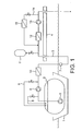
- FIG. 1 is a schematic diagram of an LCD transfer system according to the invention.
- FIG. 1 there is shown a vessel 1 having a refrigerated and pressurised LCD tank 2 connected via conduit 3 to a surface platform 4.
- a cargo pump 5 which drives LCD to a booster pump 6 which itself drives LCD to the platform via STL 7.
- Downstream of the cargo and booster pumps 5 and 6 are respectively backflow lines 8 and 9 which feed CO 2 back into the LCD container.
- the ship is also provided with a heater 10 which heats the LCD leaving the ship.
- the conduit arriving on platform 4 is provided with an expansion tank 11 to accommodate the expansion the LCD due to heating by the surroundings. Following the expansion tank 11 the conduit leads via heater 12 to injection pump 13 which serves to inject LCD down hole. Downstream of injection pump 13 the conduit is provided with a backflow line 14 which feeds excess CO 2 back to a position upstream of the heater 12. To avoid overheating of injection pump 13 during the start-up phase, backflow line 14 is itself provided with a heat exchanger 15.
Landscapes
- Engineering & Computer Science (AREA)
- Mechanical Engineering (AREA)
- General Engineering & Computer Science (AREA)
- Life Sciences & Earth Sciences (AREA)
- Environmental & Geological Engineering (AREA)
- General Life Sciences & Earth Sciences (AREA)
- Geology (AREA)
- Filling Or Discharging Of Gas Storage Vessels (AREA)
- Devices That Are Associated With Refrigeration Equipment (AREA)
- Glass Compositions (AREA)
- Details Of Reciprocating Pumps (AREA)
- Organic Low-Molecular-Weight Compounds And Preparation Thereof (AREA)
- Container, Conveyance, Adherence, Positioning, Of Wafer (AREA)
- Control Of Vehicles With Linear Motors And Vehicles That Are Magnetically Levitated (AREA)
- Carbon And Carbon Compounds (AREA)
- Transition And Organic Metals Composition Catalysts For Addition Polymerization (AREA)
- Cold Air Circulating Systems And Constructional Details In Refrigerators (AREA)
- Structures Of Non-Positive Displacement Pumps (AREA)
- Jet Pumps And Other Pumps (AREA)
- Devices For Medical Bathing And Washing (AREA)
Abstract
Description
- This invention relates to improvements in and relating to the processes and apparatus for the transfer of liquid carbon dioxide (LCD) from a water-going LCD transport vessel to an injector well-head, and to water-going LCD transport vessels.
- Carbon dioxide (CO2 is a gas produced as a by-product in large quantities in certain industrial operations, e.g. the manufacture of ammonia. Release of this by-product into the atmosphere is undesirable environmentally as it is a greenhouse gas. Much effort has thus been made towards the development of techniques for the disposal of CO2 in a way other than simple release to the atmosphere. One technique of particular interest is to pump the CO2 into porous sub-surface strata (i.e. lock), e.g. down an inj ector well in an oil field
- Subsurface disposal can be simply into porous strata or beneficial advantage of the subsurface disposal can be realised if the stratum into which it is disposed is hydrocarbon-bearing as the injected CO2 serves to drive hydrocarbon (e.g. oil or gas) in the stratum towards the producer wells (i.e. wells from which hydrocarbon is extracted). Injection of CO2 is thus one standard technique in late stage reservoir management for achieving enhanced recovery of hydrocarbons.
- The quantities of carbon dioxide involved when disposal is by subsurface injection are immense, generally of the order of millions of tonnes. This poses problems in terms of transporting the CO2 from the site at which it is created to the site at which it is injected, especially where the injection site is offshore. Carbon dioxide at ambient temperatures and pressures is gaseous and, if transported batchwise, such voluminous containers are required that the process would be unfeasible. While transport by pipeline might in some circumstances be feasible, the required infrastructure is expensive. It is therefore desirable to transport the carbon dioxide, especially to offshore injection sites, batchwise in liquid form.
- Transport of liquid carbon dioxide is however not a problem- or expense-free exercise. If the liquid CO2 is not refrigerated, the pressures required to maintain it in the liquid state are high (60-70 bar) making the required wall thicknesses of the pressurized containers high and making such containers for large scale unrefrigerated liquid CO2 transportation immensely expensive. Transport of liquid CO2 at sub-ambient temperatures reduces the required pressures and required container wall thicknesses but is expensive since refrigeration is required and, as carbon dioxide has a solid phase, there is a risk that solid carbon dioxide can form. Solid carbon dioxide formation makes CO2 transfer by pumping problematic and, due to the risks of pipe or valve blockage, potentially dangerous.
- Thus in balancing the economies of refrigeration and container cost and avoiding the risk of solid CO2 formation, in any given circumstances there will generally be a temperature and pressure which is optimal for the liquid CO2 in the containers, e.g. a temperature which is below ambient and a pressure which is above ambient but still sub-critical (the critical point of CO2 is 73.8 bar A). Typically for large scale liquid CO2 transport the optimum temperature is likely to be in the range -55 to -48°C and the pressure is likely to be 5.5 to 7.5 bar A, i.e. corresponding to the position in the phase diagram for CO2 which is just above the triple point in terms of temperature and pressure. The triple point for CO2 is 5.2 bar and -56.6°C. Higher pressures require more expensive containers; and lower pressures and temperatures raise the risk of solid formation.
- The type of pressurised containers used on water-going vessels for transport of liquefied petroleum gas (LPG) from a producer well-head to shore are not generally suitable for transport of LCD since the pressures required for LCD transport are higher. Moreover, the liquid transfer apparatus for transferring LPG from an offshore producer well to the water-going vessel (i.e. ship) are unsuitable for transfer of LCD from the vessel to an injector well-head since LPG does not pose the risk of solids formation that are encountered with LCD.
- Nonetheless there is a need for liquefied gas transport vessels that may be used for transport of LPG, LNG, PLNG and LCD transport and for transfer systems that may safely and efficiently be used for LCD transfer from transport vessel to an offshore injector well-head.
- We have now developed an LCD transfer process and apparatus that may safely and efficiently be used for LCD transfer from a transport vessel to an offshore injector well-head. The LCD containers on the transport vessels used according to the invention may moreover be used safely and efficiently to transport LPG, LNG or PLNG from an offshore producer well to shore.
-
WO 03/066423 - In the process of the invention, the vessel for use in LCD transport is preferably provided with at least two pumps, a discharge pump within the LCD container and a booster pump outside the container. The LCD is preferably contained within the container at the temperature and pressure conditions mentioned above, i.e. at a pressure above the triple point.
- It will be appreciated that the CO2 may be pumped from the container using alternatives to a conventional pump. Thus, the first'pump' may be any suitable means to discharge the CO2 from the container.
- For example, in one alternative arrangement the CO2 may be discharged from the container to the second (or booster) pump by pressurising the LCD container to displace the LCD. In this arrangement the minimum pressure of the LCD container is defined by the required pressure at the inlet of the second pump required to avoid formation of vapour bubbles in the pump inlet. The required margin to the bubble point is specified by the required Net Positive Suction Height HPSH for said second pump
- In an alternative arrangement, the LCD container can be pressurized by vaporizing LCD by means of a heat exchanger placed inside the LCD container, or by vaporizing LCD outside the LCD vessel for injection to the LCD vessel. The transport pressure will be near saturated and the pressure is increased prior to and during unloading of LCD.
- The vessel is preferably provided with a heater so that at least part of the heating of the LCD can, if necessary, occur before the LCD enters that portion of the conduit which is immersed. This serves to avoid the need for a heater on the platform or to reduce the demands on the heater on the platform or to ensure that sufficient heating capacity is available as well as to reduce the risk of the submerged section of the conduit icing up and the risk of solid carbon dioxide formation in the conduit leading from the container to the platform. This on-board heater is preferably downstream of the discharge and booster pumps. Some of the carbon dioxide from downstream of the cargo and/or booster pumps is preferably withdrawn, vaporized and fed back into the LCD container to maintain the pressure therein so as to keep the LCD above the triple point and thereby ensure optimum transfer of LCD.
- The vessel is desirably also provided with a conduit coupling by means of which at which the conduit from the container may be attached to a flexible conduit leading to a submerged turret loading (STL) system. From the STL, a further flexible conduit (a flexible riser) preferably leads to the sea bed to connect to a sub-sea flowline leading to a further rigid or flexible riser to bring the LCD to the platform. At least those parts of the conduit leading to the platform and which are not submerged are preferably thermally insulated both to prevent undue icing up and condensation from the atmosphere.
- The expansion tank on the conduit serves to ensure that the pressure within the conduit does not exceed design pressure during the period between each transfer of LCD from ship to platform. Between each transfer, the LCD in the conduit will absorb heat from the surroundings and expand. The expansion tank serves as a reservoir to accommodate that expansion and the LCD which collects in it can be fed back into the conduit during the subsequent LCD transfer operation.
- If not already at the desired temperature for down-hole injection, the LCD reaching the platform is desirably heated to such a temperature using a heater located on the platform. In general, to avoid down hole formation of gas hydrates, the LCD will be heated to about 10°C or more, preferably 12°C or more, especially 14 to 20°C. The LCD may similarly be heated to at or above 0°C to avoid down hole formation of gas hydrates. Such a temperature increase with respect to the transport temperature (i.e. the temperature in the LCD container) involves a concomitant pressure increase to avoid formation of C2 gas phase during heating and the second (booster) pump should thus have an outlet pressure which ensures the LCD is kept away from the bubble point during heating to the injection temperature.
- LCD in the conduit is fed to the inj ection pump or pumps (e.g. one, two, three or four pumps in series) to bring it to the desired pressure for injection, desirably about 150 to 350 bar, e.g. 200 to 300 bar. One or more of these pumps may be arranged for down-hole water injection when LCD injection is not taking place; however more usually different pumping systems will be used for water and LCD injection, with the conduit systems for both joining after the pumps and more preferably after the manifolds for separation of injection fluid intended for different bores in a multi-bore platform.
- Since LCD injection will generally be performed batchwise with water injection occurring between LCD injection from successive LCD transport vessels since the injection well will be kept pressurised during the changeover between water and LCD inj ections, and since there will be a time delay before the full LCD injection rate is achieved, it is desirable that, in the injection pump start-up phase, carbon dioxide from downstream of the injection pump is recycled into the carbon dioxide flow to the injection pump, optionally during this recycling with cooling.
- In a particularly preferred embodiment, the pumps and heater on the LCD transport vessel are arranged to introduce LCD into the immersed section of the flexible conduit at a temperature in the range -50°C to +0°C and at a pressure such that the CO2 is in the liquid phase and such that cavitation is avoided. More preferably, however, the booster pump is operated at a pressure which ensures the CO2 gas phase is avoided until it reaches the platform; in this event, a portion of the carbon dioxide may be separated from the main LCD flow, evaporated and recycled into the LCD container so as to maintain the pressure within the LCD container as its contents are discharged. Such a backflow line may be from the pressurised side of the cargo pump, or from the pressurised side of the booster pump. Preferably, however, there will be backflow lines from both downstream of the cargo pump and downstream of the booster pump. The first ensures the flowrate and pressure at the inlet of the booster pump before start-up is appropriate and avoids liquid to gas phase transition in the conduit at start-up. The second ensures the flowrate and pressure to the platform before start-up is appropriate and again assists in preventing undesired liquid to gas phase transition in the conduit at start-up.
- The platform is preferably provided with an expansion tank which can accumulate LCD in the period between LCD injections. This tank is preferably off the conduit and attached thereto by a valve which is pressure activated to accommodate increase in the CO2 volume as the CO2 in the conduit is heated by the surroundings. In this way unwanted release of CO2 to the atmosphere may be avoided or minimised. Alternatively the CO2 could be vented directly to atmosphere.
- The platform is also preferably provided with a backflow line from the pressured side of the injection pump to the input side of the inj ection pump. This may be done to ensure a desired flowrate and pressure during start-up until designed injection pressure and flowrate are achieved. To avoid temperature increase at a high backflow rate, the backflow line is preferably provided with a cooler, e.g. a heat exchanger.
- Desirably the transport pressure and temperature for the LCD on board ship is 5.2 to 10 bar A corresponding to a temperature of -57 to -40°C; and the pressure of the LCD as it leaves the ship is preferably 30 to 70 bar A corresponding to a temperature of -50 to 0°C. The pressure of the LCD as it leaves the injection pump depends on the particular well but typically may be 100 to 300 bar A corresponding to a temperature of 10 to 20°C.
- The containers, conduits, couplings, pumps, etc. used should therefore be such as to withstand these temperatures and pressures.
- By a surface platform herein is meant a platform at or above the water surface, e.g. either a fixed or floating platform.
- Embodiments of the invention will now be described with reference to the accompanying drawing, in which
Figure 1 is a schematic diagram of an LCD transfer system according to the invention. - Referring to
Figure 1 there is shown a vessel 1 having a refrigerated and pressurised LCD tank 2 connected viaconduit 3 to asurface platform 4. - Within the LCD container is a cargo pump 5 which drives LCD to a booster pump 6 which itself drives LCD to the platform via
STL 7. Downstream of the cargo and booster pumps 5 and 6 are respectivelybackflow lines 8 and 9 which feed CO2 back into the LCD container. The ship is also provided with aheater 10 which heats the LCD leaving the ship. The conduit arriving onplatform 4 is provided with anexpansion tank 11 to accommodate the expansion the LCD due to heating by the surroundings. Following theexpansion tank 11 the conduit leads viaheater 12 to injection pump 13 which serves to inject LCD down hole. Downstream of injection pump 13 the conduit is provided with abackflow line 14 which feeds excess CO2 back to a position upstream of theheater 12. To avoid overheating ofinjection pump 13 during the start-up phase,backflow line 14 is itself provided with aheat exchanger 15.
Claims (14)
- A process for transferring liquid carbon dioxide from a pressurised and refrigerated liquefied gas container (2) on a water -going transport vessel (1) (hereinafter "a ship") to an offshore injection well connected to a surface platform (4), said process comprising: connecting said container (2) and said platform (4) with a conduit (3) comprising a flexible section at least part of which is immersed within the water between said vessel (1) and said platform (4), a first pump (5), a second pump (6), a heater (10), an expansion tank (11), and a third pump (13); using said first pump (5), pumping liquid carbon dioxide from said container along said conduit (3) to said second pump (6); using said second pump (6) pumping said liquid carbon dioxide along said conduit (3) and past said heater (10) to said third pump (13); using said third pump (13) to pump said liquid carbon dioxide down said injection well;
characterised by:using said heater (10) heating said liquid carbon dioxide before it reaches said third pump (13), preferably before it enters said part of said flexible section which is immersed in water; using said expansion tank (11) to regulate the pressure in said conduit (3) upstream of said third pump (13) and downstream of the upstream end of said flexible section in the period before operation of said third pump (13) to pump said liquid carbon dioxide down said injection well; and using a pump or pressurised gas to transfer liquid carbon dioxide collected in said expansion tank (11) to said conduit (3) during the period of operation of said third pump to pump said liquid carbon dioxide down said injection well. - A process as claimed in claim 1, wherein the first pump (5) is a discharge pump disposed within the container (2) and the second pump (6) is a booster pump disposed outside the container (2).
- A process as claimed in claim 2, wherein the vessel (1) is provided with a heater (10) arranged to heat at least part of the liquid carbon dioxide before entering the portion of the conduit (3) which is immersed in water.
- A process as claimed in claim 3, wherein the heater (10) is disposed downstream of the discharge and booster pumps (5,6).
- A process as claimed in any preceding claim, wherein a portion of the carbon dioxide from the first and/or second pump (5,6) is withdrawn, vaporized and returned into the container (2) so as to maintain the pressure within the container (2).
- A process as claimed in any preceding claim, wherein the liquefied carbon dioxide in the container (2) is maintained above the triple point.
- A process as claimed in any preceding claim, wherein the pumps (5,6) and heater (10) are arranged to introduce liquefied carbon dioxide into the immersed section of the flexible conduit at a temperature and at a pressure such that the CO2 is in the liquid phase.
- A process as claimed in claim 7, wherein the pumps (5,6) and heater (10) are arranged to introduce liquefied carbon dioxide into the immersed section of the flexible conduit at a temperature in the range -50°C to +0°C
- An apparatus adapted to transfer liquid carbon dioxide from a pressurised and refrigerated liquefied gas container (2) on a water -going transport vessel (1) (hereinafter "a ship") to an offshore injection well connected to a surface platform (4), said apparatus comprising:a conduit (3) adapted to connect said container (2) and said platform (4), the conduit (3) comprising a flexible section at least part of which is immersed within the water between said vessel (1) and said platform (4); a first pump (5); a second pump (6); a heater (10); an expansion tank (11); and a third pump (13);wherein said first pump (5) is arranged to pump liquid carbon dioxide from said container (2) along said conduit (3) to said second pump (6); wherein said second pump (6) is arranged to pump said liquid carbon dioxide along said conduit (2) and past said heater (10) to said third pump (13); wherein said heater (10) is arranged to heat said liquid carbon dioxide before it reaches said third pump (13), preferably before it enters said part of said flexible section which is immersed in water; wherein said third pump (13) is arranged to pump said liquid carbon dioxide down said injection well; wherein said expansion tank (11) is arranged to regulate the pressure in said conduit (3) upstream of said third pump (13) and downstream of the upstream end of said flexible section in the period before operation of said third pump (13) to pump said liquid carbon dioxide down said injection well; and wherein the apparatus is arranged, such that a pump or pressurised gas is used to transfer liquid carbon dioxide collected in said expansion tank (11) to said conduit (3) during the period of operation of said third pump (13) to pump said liquid carbon dioxide down said injection well.
- An apparatus as claimed in claim 9, wherein the first pump (5) is a discharge pump disposed within the container (2) and the second pump (6) is a booster pump disposed outside the container (2).
- An apparatus as claimed in claim 10, wherein the vessel (1) is provided with a heater (10) arranged to heat at least part of the liquid carbon dioxide before entering the portion of the conduit (3) which is immersed in water.
- An apparatus as claimed in claim 11, wherein the heater (10) is disposed downstream of the discharge and booster pumps (5,6).
- An apparatus as claimed in any of claims 9 to 12, wherein the pumps (5,6) and heater (10) are arranged to introduce liquefied carbon dioxide into the immersed section of the flexible conduit (3) at a temperature and at a pressure such that the CO2 is in the liquid phase.
- An apparatus as claimed in claim 13, wherein the pumps (5,6) and heater are arranged to introduce liquefied carbon dioxide into the immersed section of the flexible conduit (3) at a temperature in the range -50°C to +0°C.
Priority Applications (2)
| Application Number | Priority Date | Filing Date | Title |
|---|---|---|---|
| EP09008384.1A EP2119952B1 (en) | 2004-07-16 | 2005-07-14 | Vessel |
| DK09008384.1T DK2119952T3 (en) | 2004-07-16 | 2005-07-14 | vessel |
Applications Claiming Priority (2)
| Application Number | Priority Date | Filing Date | Title |
|---|---|---|---|
| GB0416003A GB2416390B (en) | 2004-07-16 | 2004-07-16 | LCD Offshore Transport System |
| PCT/GB2005/002781 WO2006008486A2 (en) | 2004-07-16 | 2005-07-14 | Vessel |
Related Child Applications (2)
| Application Number | Title | Priority Date | Filing Date |
|---|---|---|---|
| EP09008384.1A Division EP2119952B1 (en) | 2004-07-16 | 2005-07-14 | Vessel |
| EP09008384.1 Division-Into | 2009-06-26 |
Publications (2)
| Publication Number | Publication Date |
|---|---|
| EP1787057A2 EP1787057A2 (en) | 2007-05-23 |
| EP1787057B1 true EP1787057B1 (en) | 2011-03-02 |
Family
ID=32893730
Family Applications (2)
| Application Number | Title | Priority Date | Filing Date |
|---|---|---|---|
| EP09008384.1A Expired - Lifetime EP2119952B1 (en) | 2004-07-16 | 2005-07-14 | Vessel |
| EP05761314A Expired - Lifetime EP1787057B1 (en) | 2004-07-16 | 2005-07-14 | Vessel |
Family Applications Before (1)
| Application Number | Title | Priority Date | Filing Date |
|---|---|---|---|
| EP09008384.1A Expired - Lifetime EP2119952B1 (en) | 2004-07-16 | 2005-07-14 | Vessel |
Country Status (16)
| Country | Link |
|---|---|
| US (1) | US8931287B2 (en) |
| EP (2) | EP2119952B1 (en) |
| JP (2) | JP4600840B2 (en) |
| KR (1) | KR100899509B1 (en) |
| CN (2) | CN100575771C (en) |
| AT (1) | ATE500465T1 (en) |
| AU (2) | AU2005263932B2 (en) |
| BR (1) | BRPI0513425B1 (en) |
| CA (1) | CA2574038C (en) |
| DE (1) | DE602005026674D1 (en) |
| DK (2) | DK1787057T3 (en) |
| EA (1) | EA009263B1 (en) |
| EG (1) | EG25031A (en) |
| GB (1) | GB2416390B (en) |
| NO (2) | NO340974B1 (en) |
| WO (1) | WO2006008486A2 (en) |
Cited By (1)
| Publication number | Priority date | Publication date | Assignee | Title |
|---|---|---|---|---|
| WO2023194765A1 (en) * | 2022-04-07 | 2023-10-12 | Totalenergies Onetech | A system for co2 storage |
Families Citing this family (48)
| Publication number | Priority date | Publication date | Assignee | Title |
|---|---|---|---|---|
| GB2416390B (en) | 2004-07-16 | 2006-07-26 | Statoil Asa | LCD Offshore Transport System |
| US20060156742A1 (en) * | 2005-01-20 | 2006-07-20 | Farese David J | Cryogenic fluid supply method and apparatus |
| US20130180620A1 (en) * | 2005-01-21 | 2013-07-18 | Andreas Praller | Carbon dioxide supply for injection-molding systems |
| DE102005002976A1 (en) * | 2005-01-21 | 2006-07-27 | Linde Ag | Carbon dioxide supply for injection molding plants |
| GB0614250D0 (en) * | 2006-07-18 | 2006-08-30 | Ntnu Technology Transfer As | Apparatus and Methods for Natural Gas Transportation and Processing |
| WO2008097099A1 (en) * | 2007-02-08 | 2008-08-14 | Knutsen Oas Shipping As | Method and device for transport of gas |
| KR101103703B1 (en) | 2008-12-15 | 2012-01-11 | 대우조선해양 주식회사 | Ships equipped with carbon dioxide storage tanks and operating methods of the ships |
| KR101131578B1 (en) * | 2009-04-23 | 2012-04-12 | 한국과학기술원 | Cargo handling system and method for liquefied gas carrier |
| GB0910859D0 (en) | 2009-06-24 | 2009-08-05 | Tamacrest Ltd | Carbon capture and storage using minimal offshore structures |
| KR101106570B1 (en) * | 2009-07-17 | 2012-01-19 | 한국과학기술원 | High pressure liquid cargo loading and unloading method and equipment using pump and unmixed driving liquid |
| KR101085706B1 (en) * | 2009-07-20 | 2011-11-21 | 한외현 | Fire oxygen breathing apparatus with emergency light |
| WO2011019096A1 (en) * | 2009-08-11 | 2011-02-17 | 한국해양연구원 | Floating dock type liquid carbon dioxide transport ship and transport method thereof |
| AP3930A (en) * | 2009-10-06 | 2016-12-16 | Mi Llc | Method for hydrocarbon removal and recovery from drill cuttings |
| DE102009047117B4 (en) * | 2009-11-25 | 2016-06-16 | Tge Marine Gas Engineering Gmbh | Method and system for unloading a cargo tank for cryogenic liquefied gas |
| CN101788106B (en) * | 2010-02-10 | 2011-08-03 | 毛恒松 | Deep-lying storage method of carbon dioxide |
| CN102155614B (en) * | 2011-01-21 | 2013-05-01 | 中国石油天然气股份有限公司 | A method and system for recovering natural gas from marginal offshore oilfields |
| JP5606466B2 (en) * | 2012-02-07 | 2014-10-15 | 岩谷産業株式会社 | Gas supply device |
| CN102582796A (en) * | 2012-03-19 | 2012-07-18 | 大连海事大学 | A natural gas storage and transport ship |
| KR101379954B1 (en) * | 2012-03-22 | 2014-03-28 | 삼성중공업 주식회사 | Carbon Dioxide Handling System and Method |
| FR2993343B1 (en) * | 2012-07-13 | 2015-06-05 | Air Liquide | METHOD AND APPARATUS FOR VAPORIZATION OF CARBON DIOXIDE-RICH LIQUID |
| CN203384645U (en) * | 2012-10-02 | 2014-01-08 | 查特股份有限公司 | Cryogenic liquid conveying and supercharging system with active supercharging capability |
| KR101277844B1 (en) | 2013-03-28 | 2013-06-21 | 현대중공업 주식회사 | A fuel gas supply system of liquefied natural gas and driving method thereof |
| US9846109B2 (en) * | 2015-10-27 | 2017-12-19 | Sgs North America Inc. | Fluid sampling |
| NO349652B1 (en) * | 2016-04-01 | 2026-03-23 | Mirade Consultants Ltd | Improved Techniques in the upstream oil and gas industry |
| US10054267B2 (en) * | 2016-05-27 | 2018-08-21 | GM Global Technology Operations LLC | Pressure vessel array |
| WO2018234721A1 (en) * | 2017-06-21 | 2018-12-27 | Mirade Consultants Ltd | METHOD AND APPARATUS FOR ASSISTED RECOVERY OF CO2 BASED OIL AT SEA |
| CN107524911B (en) * | 2017-09-18 | 2019-04-23 | 中国船舶科学研究中心(中国船舶重工集团公司第七0二研究所) | Liquid oxygen filling and recovery system of underwater working platform |
| JP7548898B2 (en) * | 2018-04-06 | 2024-09-10 | エイチディー コリア シップビルディング アンド オフショア エンジニアリング カンパニー リミテッド | Gas processing system and vessel containing same |
| KR20240033115A (en) * | 2018-06-01 | 2024-03-12 | 스틸헤드 엘엔지 (에이에스엘엔지) 엘티디. | Liquefaction apparatus, methods, and systems |
| CN109466702B (en) * | 2018-12-21 | 2024-02-20 | 南京盛航海运股份有限公司 | Liquid cargo ship residual liquid collecting system |
| CN113195961B (en) * | 2019-01-25 | 2023-05-23 | 沙特阿拉伯石油公司 | For transporting liquid hydrocarbons and CO 2 To pass through CO 2 Process and method for capturing hydrogen gas |
| JP7350647B2 (en) * | 2019-12-19 | 2023-09-26 | 三菱造船株式会社 | How to load liquefied carbon dioxide on ships and ships |
| NO346899B1 (en) | 2020-12-18 | 2023-02-20 | Tore Lea | A ship and a method for bringing liquified gas from an onshore terminal across a sea to a subsurface permanent storage reservoir |
| KR102513245B1 (en) * | 2021-02-22 | 2023-03-22 | 중앙대학교 산학협력단 | Gas supply system for driving Pneumatic Actuator and Operation method thereof |
| JP7699454B2 (en) * | 2021-03-31 | 2025-06-27 | 三菱造船株式会社 | Method for adjusting tank pressure on ships and vessels |
| KR102710840B1 (en) * | 2021-10-20 | 2024-09-27 | 에이치디현대중공업 주식회사 | Vessels including methanol fueling system |
| CN116476994A (en) * | 2022-01-13 | 2023-07-25 | 大连船舶重工集团有限公司 | A liquid CO2 transfer system using hose |
| CN115199937B (en) * | 2022-07-25 | 2023-07-18 | 江南造船(集团)有限责任公司 | Carbon dioxide transport ship cabin pressure control method and system and carbon dioxide transport ship |
| JP7245949B1 (en) * | 2022-08-24 | 2023-03-24 | 三菱造船株式会社 | Liquefied carbon dioxide equipment, method for estimating generation status of dry ice |
| US12331888B2 (en) * | 2023-02-01 | 2025-06-17 | Kraken Technology Holdings, LLC | Process for cold energy utilization from a liquid carbon dioxide receiving facility |
| EP4658876A1 (en) * | 2023-02-03 | 2025-12-10 | TotalEnergies OneTech | Conditioning method for carbon dioxide storage in a subterranean reservoir |
| EP4417860B1 (en) * | 2023-02-15 | 2025-04-09 | Horisont Energi AS | System and method for refrigeration of contents of an lco2 intermediate storage tank at a co2 receiving terminal |
| WO2025012670A1 (en) * | 2023-07-12 | 2025-01-16 | Totalenergies Onetech | Overpressure protection system and overpressure protection method |
| JP2025021741A (en) | 2023-08-01 | 2025-02-14 | 三菱造船株式会社 | Carbon dioxide metering system, ship, and carbon dioxide metering method |
| JP2025037623A (en) | 2023-09-06 | 2025-03-18 | 三菱造船株式会社 | Carbon dioxide capture system, ship, and carbon dioxide capture method |
| EP4650746A1 (en) * | 2024-05-17 | 2025-11-19 | Meter-Q Solutions GmbH | Extraction probe for sampling carbon dioxide |
| WO2026094115A1 (en) * | 2024-10-28 | 2026-05-07 | 日揮グローバル株式会社 | Liquefied co2 supply system, method for discharging liquefied co2, and method for starting supply of liquefied co2 |
| CN119687367B (en) * | 2024-12-19 | 2025-11-14 | 大连船舶重工集团有限公司 | A solution for multiple liquid CO2 storage tanks sharing a single liquid cargo system |
Family Cites Families (33)
| Publication number | Priority date | Publication date | Assignee | Title |
|---|---|---|---|---|
| US3106071A (en) * | 1961-08-16 | 1963-10-08 | Exxon Research Engineering Co | System for filling closed containers with volatile liquids |
| GB1315302A (en) * | 1969-06-10 | 1973-05-02 | Int Research & Dev Co Ltd | Rotary electrical machines |
| DE2048271C3 (en) * | 1970-10-01 | 1979-08-23 | Liquid Gas International Gmbh, 5480 Remagen | Device for loading and unloading containers for liquid gas and the like, in particular for liquid gas containers on ships |
| JPS5314770B2 (en) * | 1972-07-03 | 1978-05-19 | ||
| SU551476A1 (en) * | 1973-01-02 | 1977-03-25 | Всесоюзный Научно-Исследовательский И Проектный Институт Технологии Химического И Нефтяного Машиностроения | Liquefied gas pumping device |
| US4212354A (en) * | 1979-03-19 | 1980-07-15 | Service Fracturing Company and Airry, Inc. | Method for injecting carbon dioxide into a well |
| JP3021004B2 (en) * | 1989-07-19 | 2000-03-15 | 三菱重工業株式会社 | Method and apparatus for introducing carbon dioxide into the deep sea |
| JPH04297392A (en) * | 1991-03-26 | 1992-10-21 | Mitsubishi Heavy Ind Ltd | Carbonic acid gas transport ship |
| US5243821A (en) * | 1991-06-24 | 1993-09-14 | Air Products And Chemicals, Inc. | Method and apparatus for delivering a continuous quantity of gas over a wide range of flow rates |
| US5129759A (en) * | 1991-07-23 | 1992-07-14 | Pb-Kbb, Inc. | Offshore storage facility and terminal |
| US5482919A (en) * | 1993-09-15 | 1996-01-09 | American Superconductor Corporation | Superconducting rotor |
| US6089022A (en) * | 1998-03-18 | 2000-07-18 | Mobil Oil Corporation | Regasification of liquefied natural gas (LNG) aboard a transport vessel |
| EP0962384A1 (en) * | 1998-06-05 | 1999-12-08 | Single Buoy Moorings Inc. | Loading arrangement |
| RU2198285C2 (en) * | 1998-07-13 | 2003-02-10 | Всероссийский научно-исследовательский институт природных газов и газовых технологий Российского акционерного общества "Газпром" | Method of recovery and transportation of natural gas from flowers and bees gas and gas-hydrate offshore fields |
| FR2781868B1 (en) * | 1998-07-29 | 2000-09-15 | Air Liquide | PLANT AND METHOD FOR PROVIDING HELIUM WITH MULTIPLE PRODUCTION LINES |
| US6244053B1 (en) * | 1999-03-08 | 2001-06-12 | Mobil Oil Corporation | System and method for transferring cryogenic fluids |
| US6224355B1 (en) * | 1999-04-20 | 2001-05-01 | Occidental Permian Ltd. | Carbon dioxide pump and pumping system |
| EG22932A (en) * | 2000-05-31 | 2002-01-13 | Shell Int Research | Method and system for reducing longitudinal fluid flow around a permeable well tubular |
| JP4493806B2 (en) * | 2000-06-29 | 2010-06-30 | 大陽日酸株式会社 | Liquid gas delivery equipment |
| US6517286B1 (en) * | 2001-02-06 | 2003-02-11 | Spectrum Energy Services, Llc | Method for handling liquified natural gas (LNG) |
| JP4763915B2 (en) * | 2001-05-23 | 2011-08-31 | 三菱重工業株式会社 | Liquefied carbon dioxide storage / discharge device and liquefied carbon dioxide underwater injection system |
| US7018249B2 (en) * | 2001-11-29 | 2006-03-28 | Siemens Aktiengesellschaft | Boat propulsion system |
| NO324883B1 (en) * | 2001-12-03 | 2007-12-27 | Statoil Asa | Vessel |
| MXPA04006035A (en) * | 2001-12-19 | 2005-08-19 | Conversion Gas Imp S L P | Method and apparatus for warming and storage of cold fluids. |
| DE10205130A1 (en) * | 2002-02-07 | 2003-08-28 | Air Liquide Gmbh | Process for the uninterrupted provision of liquid, supercooled carbon dioxide at constant pressure above 40 bar and supply system |
| JP4163908B2 (en) * | 2002-07-10 | 2008-10-08 | 大陽日酸株式会社 | High-pressure gas metering device |
| JP2004125039A (en) * | 2002-10-01 | 2004-04-22 | Mitsubishi Heavy Ind Ltd | Co2 transporting method, fluid storing device, plug shooting device, plug recovering device, and fluid storing method |
| GB2396138B (en) * | 2002-12-12 | 2004-10-27 | Bluewater Terminal Systems Nv | Off-shore mooring and fluid transfer system |
| GB0320474D0 (en) * | 2003-09-01 | 2003-10-01 | Cryostar France Sa | Controlled storage of liquefied gases |
| US7322387B2 (en) * | 2003-09-04 | 2008-01-29 | Freeport-Mcmoran Energy Llc | Reception, processing, handling and distribution of hydrocarbons and other fluids |
| GB2416390B (en) | 2004-07-16 | 2006-07-26 | Statoil Asa | LCD Offshore Transport System |
| DE102005005283A1 (en) * | 2005-02-04 | 2006-08-17 | Siemens Ag | Machine system with thermosyphon cooling of its superconducting rotor winding |
| US7821164B2 (en) * | 2007-02-15 | 2010-10-26 | General Electric Company | Method and apparatus for a superconducting generator driven by wind turbine |
-
2004
- 2004-07-16 GB GB0416003A patent/GB2416390B/en not_active Expired - Lifetime
-
2005
- 2005-07-14 BR BRPI0513425-0A patent/BRPI0513425B1/en not_active IP Right Cessation
- 2005-07-14 AU AU2005263932A patent/AU2005263932B2/en not_active Ceased
- 2005-07-14 CA CA2574038A patent/CA2574038C/en not_active Expired - Lifetime
- 2005-07-14 KR KR1020077003794A patent/KR100899509B1/en not_active Expired - Fee Related
- 2005-07-14 DE DE602005026674T patent/DE602005026674D1/en not_active Expired - Lifetime
- 2005-07-14 EP EP09008384.1A patent/EP2119952B1/en not_active Expired - Lifetime
- 2005-07-14 US US11/632,491 patent/US8931287B2/en active Active
- 2005-07-14 JP JP2007520897A patent/JP4600840B2/en not_active Expired - Fee Related
- 2005-07-14 CN CN200580029387A patent/CN100575771C/en not_active Expired - Fee Related
- 2005-07-14 EA EA200700043A patent/EA009263B1/en not_active IP Right Cessation
- 2005-07-14 AT AT05761314T patent/ATE500465T1/en not_active IP Right Cessation
- 2005-07-14 DK DK05761314.3T patent/DK1787057T3/en active
- 2005-07-14 EP EP05761314A patent/EP1787057B1/en not_active Expired - Lifetime
- 2005-07-14 DK DK09008384.1T patent/DK2119952T3/en active
- 2005-07-14 WO PCT/GB2005/002781 patent/WO2006008486A2/en not_active Ceased
- 2005-07-14 CN CN200910169658A patent/CN101704404A/en active Pending
-
2007
- 2007-01-15 EG EGNA2007000034 patent/EG25031A/en active
- 2007-02-16 NO NO20070900A patent/NO340974B1/en unknown
-
2009
- 2009-07-01 AU AU2009202676A patent/AU2009202676B2/en not_active Ceased
-
2010
- 2010-04-23 JP JP2010099632A patent/JP2010266068A/en active Pending
-
2017
- 2017-02-20 NO NO20170246A patent/NO342113B1/en unknown
Cited By (1)
| Publication number | Priority date | Publication date | Assignee | Title |
|---|---|---|---|---|
| WO2023194765A1 (en) * | 2022-04-07 | 2023-10-12 | Totalenergies Onetech | A system for co2 storage |
Also Published As
Similar Documents
| Publication | Publication Date | Title |
|---|---|---|
| EP2119952B1 (en) | Vessel | |
| EP1290388B1 (en) | Method for producing, transporting, offloading, storing and distributing natural gas to a marketplace | |
| US5511905A (en) | Direct injection of cold fluids into a subterranean cavern | |
| CN101506466B (en) | System, vessel and method for production of oil and heavier gas fractions from a reservoir below the seabed | |
| US8789593B2 (en) | Enhancing water recovery in subterranean wells with a cryogenic pump | |
| US20090013697A1 (en) | Simultaneous Underground Cavern Development and Fluid Storage | |
| WO1998031919A1 (en) | Method and apparatus for producing and shipping hydrocarbons offshore | |
| EP1912863B1 (en) | Easy systems for cryogenic fluids transfer | |
| CN110959064A (en) | Improved technologies for the upstream oil and gas industry | |
| EP4414601B1 (en) | System and method for pressure-maintenance of an intermediate storage tank during lco2 injection at an lco2 receiving terminal | |
| AU735485B2 (en) | Method and apparatus for producing and shipping hydrocarbons offshore | |
| GB2356183A (en) | Method and apparatus for producing and storing hydrocarbons offshore |
Legal Events
| Date | Code | Title | Description |
|---|---|---|---|
| PUAI | Public reference made under article 153(3) epc to a published international application that has entered the european phase |
Free format text: ORIGINAL CODE: 0009012 |
|
| 17P | Request for examination filed |
Effective date: 20070129 |
|
| AK | Designated contracting states |
Kind code of ref document: A2 Designated state(s): AT BE BG CH CY CZ DE DK EE ES FI FR GB GR HU IE IS IT LI LT LU LV MC NL PL PT RO SE SI SK TR |
|
| RIN1 | Information on inventor provided before grant (corrected) |
Inventor name: OMA, NARVE Inventor name: ASPELUND, AUDUN Inventor name: WONGRAVEN, LEIF, ROAR Inventor name: HENNINGSEN, ROAR, FRODE Inventor name: HILDEN, TOR, ERIK Inventor name: FIVELSTAD, JAN, EINAR Inventor name: SANDVIK, TOR, ERLING Inventor name: KROGSTAD, HENRIK |
|
| DAX | Request for extension of the european patent (deleted) | ||
| 17Q | First examination report despatched |
Effective date: 20071107 |
|
| RAP1 | Party data changed (applicant data changed or rights of an application transferred) |
Owner name: SINVENT AS Owner name: FABRICOM AS Owner name: TEEKAY NORWAY AS Owner name: STATOILHYDRO ASA |
|
| GRAP | Despatch of communication of intention to grant a patent |
Free format text: ORIGINAL CODE: EPIDOSNIGR1 |
|
| GRAA | (expected) grant |
Free format text: ORIGINAL CODE: 0009210 |
|
| GRAS | Grant fee paid |
Free format text: ORIGINAL CODE: EPIDOSNIGR3 |
|
| AK | Designated contracting states |
Kind code of ref document: B1 Designated state(s): AT BE BG CH CY CZ DE DK EE ES FI FR GB GR HU IE IS IT LI LT LU LV MC NL PL PT RO SE SI SK TR |
|
| REG | Reference to a national code |
Ref country code: GB Ref legal event code: FG4D |
|
| REG | Reference to a national code |
Ref country code: CH Ref legal event code: EP |
|
| REG | Reference to a national code |
Ref country code: IE Ref legal event code: FG4D |
|
| REF | Corresponds to: |
Ref document number: 602005026674 Country of ref document: DE Date of ref document: 20110414 Kind code of ref document: P |
|
| REG | Reference to a national code |
Ref country code: DE Ref legal event code: R096 Ref document number: 602005026674 Country of ref document: DE Effective date: 20110414 |
|
| REG | Reference to a national code |
Ref country code: NL Ref legal event code: T3 |
|
| REG | Reference to a national code |
Ref country code: DK Ref legal event code: T3 |
|
| PG25 | Lapsed in a contracting state [announced via postgrant information from national office to epo] |
Ref country code: ES Free format text: LAPSE BECAUSE OF FAILURE TO SUBMIT A TRANSLATION OF THE DESCRIPTION OR TO PAY THE FEE WITHIN THE PRESCRIBED TIME-LIMIT Effective date: 20110613 Ref country code: SE Free format text: LAPSE BECAUSE OF FAILURE TO SUBMIT A TRANSLATION OF THE DESCRIPTION OR TO PAY THE FEE WITHIN THE PRESCRIBED TIME-LIMIT Effective date: 20110302 Ref country code: LT Free format text: LAPSE BECAUSE OF FAILURE TO SUBMIT A TRANSLATION OF THE DESCRIPTION OR TO PAY THE FEE WITHIN THE PRESCRIBED TIME-LIMIT Effective date: 20110302 Ref country code: GR Free format text: LAPSE BECAUSE OF FAILURE TO SUBMIT A TRANSLATION OF THE DESCRIPTION OR TO PAY THE FEE WITHIN THE PRESCRIBED TIME-LIMIT Effective date: 20110603 Ref country code: LV Free format text: LAPSE BECAUSE OF FAILURE TO SUBMIT A TRANSLATION OF THE DESCRIPTION OR TO PAY THE FEE WITHIN THE PRESCRIBED TIME-LIMIT Effective date: 20110302 |
|
| LTIE | Lt: invalidation of european patent or patent extension |
Effective date: 20110302 |
|
| PG25 | Lapsed in a contracting state [announced via postgrant information from national office to epo] |
Ref country code: CY Free format text: LAPSE BECAUSE OF FAILURE TO SUBMIT A TRANSLATION OF THE DESCRIPTION OR TO PAY THE FEE WITHIN THE PRESCRIBED TIME-LIMIT Effective date: 20110302 Ref country code: SI Free format text: LAPSE BECAUSE OF FAILURE TO SUBMIT A TRANSLATION OF THE DESCRIPTION OR TO PAY THE FEE WITHIN THE PRESCRIBED TIME-LIMIT Effective date: 20110302 Ref country code: BG Free format text: LAPSE BECAUSE OF FAILURE TO SUBMIT A TRANSLATION OF THE DESCRIPTION OR TO PAY THE FEE WITHIN THE PRESCRIBED TIME-LIMIT Effective date: 20110602 Ref country code: AT Free format text: LAPSE BECAUSE OF FAILURE TO SUBMIT A TRANSLATION OF THE DESCRIPTION OR TO PAY THE FEE WITHIN THE PRESCRIBED TIME-LIMIT Effective date: 20110302 Ref country code: FI Free format text: LAPSE BECAUSE OF FAILURE TO SUBMIT A TRANSLATION OF THE DESCRIPTION OR TO PAY THE FEE WITHIN THE PRESCRIBED TIME-LIMIT Effective date: 20110302 |
|
| PG25 | Lapsed in a contracting state [announced via postgrant information from national office to epo] |
Ref country code: BE Free format text: LAPSE BECAUSE OF FAILURE TO SUBMIT A TRANSLATION OF THE DESCRIPTION OR TO PAY THE FEE WITHIN THE PRESCRIBED TIME-LIMIT Effective date: 20110302 |
|
| PG25 | Lapsed in a contracting state [announced via postgrant information from national office to epo] |
Ref country code: PT Free format text: LAPSE BECAUSE OF FAILURE TO SUBMIT A TRANSLATION OF THE DESCRIPTION OR TO PAY THE FEE WITHIN THE PRESCRIBED TIME-LIMIT Effective date: 20110704 Ref country code: EE Free format text: LAPSE BECAUSE OF FAILURE TO SUBMIT A TRANSLATION OF THE DESCRIPTION OR TO PAY THE FEE WITHIN THE PRESCRIBED TIME-LIMIT Effective date: 20110302 |
|
| PG25 | Lapsed in a contracting state [announced via postgrant information from national office to epo] |
Ref country code: SK Free format text: LAPSE BECAUSE OF FAILURE TO SUBMIT A TRANSLATION OF THE DESCRIPTION OR TO PAY THE FEE WITHIN THE PRESCRIBED TIME-LIMIT Effective date: 20110302 Ref country code: RO Free format text: LAPSE BECAUSE OF FAILURE TO SUBMIT A TRANSLATION OF THE DESCRIPTION OR TO PAY THE FEE WITHIN THE PRESCRIBED TIME-LIMIT Effective date: 20110302 Ref country code: IS Free format text: LAPSE BECAUSE OF FAILURE TO SUBMIT A TRANSLATION OF THE DESCRIPTION OR TO PAY THE FEE WITHIN THE PRESCRIBED TIME-LIMIT Effective date: 20110702 Ref country code: CZ Free format text: LAPSE BECAUSE OF FAILURE TO SUBMIT A TRANSLATION OF THE DESCRIPTION OR TO PAY THE FEE WITHIN THE PRESCRIBED TIME-LIMIT Effective date: 20110302 |
|
| PLBE | No opposition filed within time limit |
Free format text: ORIGINAL CODE: 0009261 |
|
| STAA | Information on the status of an ep patent application or granted ep patent |
Free format text: STATUS: NO OPPOSITION FILED WITHIN TIME LIMIT |
|
| PGFP | Annual fee paid to national office [announced via postgrant information from national office to epo] |
Ref country code: IE Payment date: 20111014 Year of fee payment: 7 |
|
| 26N | No opposition filed |
Effective date: 20111205 |
|
| PG25 | Lapsed in a contracting state [announced via postgrant information from national office to epo] |
Ref country code: MC Free format text: LAPSE BECAUSE OF NON-PAYMENT OF DUE FEES Effective date: 20110731 Ref country code: PL Free format text: LAPSE BECAUSE OF FAILURE TO SUBMIT A TRANSLATION OF THE DESCRIPTION OR TO PAY THE FEE WITHIN THE PRESCRIBED TIME-LIMIT Effective date: 20110302 |
|
| REG | Reference to a national code |
Ref country code: CH Ref legal event code: PL |
|
| GBPC | Gb: european patent ceased through non-payment of renewal fee |
Effective date: 20110714 |
|
| REG | Reference to a national code |
Ref country code: DE Ref legal event code: R097 Ref document number: 602005026674 Country of ref document: DE Effective date: 20111205 |
|
| REG | Reference to a national code |
Ref country code: FR Ref legal event code: ST Effective date: 20120330 |
|
| PG25 | Lapsed in a contracting state [announced via postgrant information from national office to epo] |
Ref country code: FR Free format text: LAPSE BECAUSE OF NON-PAYMENT OF DUE FEES Effective date: 20110801 Ref country code: LI Free format text: LAPSE BECAUSE OF NON-PAYMENT OF DUE FEES Effective date: 20110731 Ref country code: CH Free format text: LAPSE BECAUSE OF NON-PAYMENT OF DUE FEES Effective date: 20110731 |
|
| PG25 | Lapsed in a contracting state [announced via postgrant information from national office to epo] |
Ref country code: IT Free format text: LAPSE BECAUSE OF FAILURE TO SUBMIT A TRANSLATION OF THE DESCRIPTION OR TO PAY THE FEE WITHIN THE PRESCRIBED TIME-LIMIT Effective date: 20110302 |
|
| PG25 | Lapsed in a contracting state [announced via postgrant information from national office to epo] |
Ref country code: GB Free format text: LAPSE BECAUSE OF NON-PAYMENT OF DUE FEES Effective date: 20110714 |
|
| REG | Reference to a national code |
Ref country code: IE Ref legal event code: MM4A |
|
| PG25 | Lapsed in a contracting state [announced via postgrant information from national office to epo] |
Ref country code: LU Free format text: LAPSE BECAUSE OF NON-PAYMENT OF DUE FEES Effective date: 20110714 |
|
| PG25 | Lapsed in a contracting state [announced via postgrant information from national office to epo] |
Ref country code: IE Free format text: LAPSE BECAUSE OF NON-PAYMENT OF DUE FEES Effective date: 20120714 |
|
| PG25 | Lapsed in a contracting state [announced via postgrant information from national office to epo] |
Ref country code: TR Free format text: LAPSE BECAUSE OF FAILURE TO SUBMIT A TRANSLATION OF THE DESCRIPTION OR TO PAY THE FEE WITHIN THE PRESCRIBED TIME-LIMIT Effective date: 20110302 |
|
| PG25 | Lapsed in a contracting state [announced via postgrant information from national office to epo] |
Ref country code: HU Free format text: LAPSE BECAUSE OF FAILURE TO SUBMIT A TRANSLATION OF THE DESCRIPTION OR TO PAY THE FEE WITHIN THE PRESCRIBED TIME-LIMIT Effective date: 20110302 |
|
| REG | Reference to a national code |
Ref country code: DE Ref legal event code: R082 Ref document number: 602005026674 Country of ref document: DE Representative=s name: DEHNS GERMANY PARTNERSCHAFT MBB, DE Ref country code: DE Ref legal event code: R082 Ref document number: 602005026674 Country of ref document: DE Representative=s name: DEHNSGERMANY PARTNERSCHAFT VON PATENTANWAELTEN, DE |
|
| P01 | Opt-out of the competence of the unified patent court (upc) registered |
Effective date: 20230524 |
|
| PGFP | Annual fee paid to national office [announced via postgrant information from national office to epo] |
Ref country code: NL Payment date: 20230718 Year of fee payment: 19 |
|
| PGFP | Annual fee paid to national office [announced via postgrant information from national office to epo] |
Ref country code: DK Payment date: 20230719 Year of fee payment: 19 Ref country code: DE Payment date: 20230719 Year of fee payment: 19 |
|
| REG | Reference to a national code |
Ref country code: DE Ref legal event code: R119 Ref document number: 602005026674 Country of ref document: DE |
|
| REG | Reference to a national code |
Ref country code: DK Ref legal event code: EBP Effective date: 20240731 |
|
| REG | Reference to a national code |
Ref country code: NL Ref legal event code: MM Effective date: 20240801 |
|
| PG25 | Lapsed in a contracting state [announced via postgrant information from national office to epo] |
Ref country code: DE Free format text: LAPSE BECAUSE OF NON-PAYMENT OF DUE FEES Effective date: 20250201 |
|
| PG25 | Lapsed in a contracting state [announced via postgrant information from national office to epo] |
Ref country code: NL Free format text: LAPSE BECAUSE OF NON-PAYMENT OF DUE FEES Effective date: 20240801 |
|
| PG25 | Lapsed in a contracting state [announced via postgrant information from national office to epo] |
Ref country code: DK Free format text: LAPSE BECAUSE OF NON-PAYMENT OF DUE FEES Effective date: 20240731 |