EP1786998B1 - Electromechanical programmable lock and its operating system - Google Patents
Electromechanical programmable lock and its operating system Download PDFInfo
- Publication number
- EP1786998B1 EP1786998B1 EP05756278A EP05756278A EP1786998B1 EP 1786998 B1 EP1786998 B1 EP 1786998B1 EP 05756278 A EP05756278 A EP 05756278A EP 05756278 A EP05756278 A EP 05756278A EP 1786998 B1 EP1786998 B1 EP 1786998B1
- Authority
- EP
- European Patent Office
- Prior art keywords
- lock
- generator
- key
- electric
- control unit
- Prior art date
- Legal status (The legal status is an assumption and is not a legal conclusion. Google has not performed a legal analysis and makes no representation as to the accuracy of the status listed.)
- Expired - Lifetime
Links
Images


Classifications
-
- E—FIXED CONSTRUCTIONS
- E05—LOCKS; KEYS; WINDOW OR DOOR FITTINGS; SAFES
- E05B—LOCKS; ACCESSORIES THEREFOR; HANDCUFFS
- E05B47/00—Operating or controlling locks or other fastening devices by electric or magnetic means
- E05B47/06—Controlling mechanically-operated bolts by electro-magnetically-operated detents
- E05B47/0611—Cylinder locks with electromagnetic control
- E05B47/0619—Cylinder locks with electromagnetic control by blocking the rotor
- E05B47/0626—Cylinder locks with electromagnetic control by blocking the rotor radially
- E05B47/0634—Cylinder locks with electromagnetic control by blocking the rotor radially with a pivotally moveable blocking element
-
- E—FIXED CONSTRUCTIONS
- E05—LOCKS; KEYS; WINDOW OR DOOR FITTINGS; SAFES
- E05B—LOCKS; ACCESSORIES THEREFOR; HANDCUFFS
- E05B47/00—Operating or controlling locks or other fastening devices by electric or magnetic means
- E05B2047/0048—Circuits, feeding, monitoring
- E05B2047/0057—Feeding
- E05B2047/0062—Feeding by generator
Definitions
- the invention relates to an electromechanical programmable lock and its operating system.
- a locking system based on a programmable, electronic key can be implemented either as centralized or decentralized or as a combination thereof.
- a centralized system consists of an electricity supply and telecommunications network, electrically operated lock bodies, electronic key reading devices, electronic keys, generally containing only a code, programmable control units and backup batteries.
- a centralized system provides good properties, but is expensive to implement especially in an old building, in which no provision has been made for the cabling required by the system.
- a decentralized system generally makes an independent opening decision in the lock control unit on the basis of information programmed in the key.
- the power supply of the system has typically been implemented by a power source feeding the lock control unit and/or a backup battery.
- the power supply of a decentralized system can also be implemented by a battery in the key.
- the maintenance of the batteries of the locks and keys is problematic, because the draining of the batteries prevents opening the lock or they leave the lock in the open position.
- the key includes a memory element, which can be read and identified by the reading circuit in the lock. If the lock recognizes the electric identifier of the key, the lock opens either by turning the key set in the lock or by the operation of an electric opening mechanism.
- a locking code has been saved in the key.
- the key also includes a small battery, by which the key code can be sent to the lock.
- Another exemplary solution of the use of an electric key identifier is known from the application WO 00/68536 . However, both systems require an external energy source for carrying out the electric recognition and electric opening of the lock.
- Publication DE 19918817 discloses a procedure, in which the key has been provided with an arrangement creating electricity.
- the electricity is produced by means of a mass moving in the key, which operates an electric generator.
- the mass in the key moves when the person is moving, thereby creating a small electric current.
- the electricity produced is loaded to a battery in the key.
- the energy of the battery is used in sending the code of the key to the lock.
- a lock which is independent of an external energy source and at least partly electrically operated, can also be implemented by using the piezoelectric phenomenon.
- An arrangement, in which piezoelectric elements have been installed in the body of the lock, is known from the patent US 6 437 684 . Inserting the key in the lock and turning it in the lock creates a deformation in the piezoelements, which creates an electric current. This current is utilized in the management of the locking.
- the objective of the invention is to provide a new lock and locking method, by which an electromechanic, programmable lock system can be implemented without a separate, electric power source.
- a lock arrangement in which mechanical power transmission has been arranged from a turnable lock cylinder to an electric generator turnably fastened to the lock body, the turning angle of which depends on the torque transmitted by it.
- electric current is first produced by an electric generator to the electric key identification system of the lock. Then the electrical load of the generator does not produce a high torque. If the key is identified and accepted to be used for opening the lock, the output arrangement of the generator is changed so that the torque transmitted by the generator increases strongly. Turning the key then also causes the turning of the body of the electric generator, as a result of which the mechanical detent is removed from the opening path of the lock. After this, the lock opens fully mechanically by turning the key further.
- the invention has the advantage that an electric lock system can be implemented without a separate electric actuator and the storage of electric energy required by it.
- the invention has the advantage that electric identification can be used in the lock, which enables the use of more versatile protection arrangements than a conventional mechanical locking system.
- a further advantage of the invention is the fact that electric energy is required only for the identification and acceptance of the key and the coupling arrangements of the terminals of the generator.
- Yet another advantage of the invention is easy electric programmability of the lock and the key, which enables changing the locking system easily.
- An additional advantage of the invention is the fact that the key bit can be smooth, or only one projection or groove is required in it to enable drawing the door open by the key.
- Another additional advantage of the invention is the fact that the lock can be opened mechanically by turning the key, and no electric energy is required for opening it.
- the electromechanical lock according to the invention is characterized in that the electric energy required by the electric identification has been produced from the movement of the key by an electromagnetic generator, and that the difference between the torque transmitted by the loaded and unloaded electromagnetic generator has been arranged either to open the lock or to bring it to the blocking state.
- the electromechanical locking method according to the invention is characterized in that the electric energy required by the electric identification of the key is produced by the movement of the key by means of an electromagnetic generator, and that the difference between the torque of the loaded and unloaded electromagnetic generator is used either to open the lock or to bring it to the blocking state.
- the basic idea of the invention is the following: Electrical identification and acceptance of the key and mechanical opening motion of the lock bolt are both utilized in the lock.
- the key is identified and accepted electrically, but the motion of the bolt is achieved mechanically by turning the key.
- the key turns sufficiently for moving the bolt only if the key has been identified.
- an unaccepted key turns freely around in the lock body without a mechanical connection to the lock bolt.
- the electric energy required for the identification and acceptance is produced in the lock by an electromagnetic generator, the rotor of which is turned by turning the key.
- the motion of the key to the rotor of the generator is transmitted from the lock cylinder by a gear system.
- the body of a direct-current generator has been installed in the lock body so that the direct-current generator can be turned around its longitudinal axis.
- control unit of the lock finds that the key turned in the lock is not allowed to open the lock, the control unit changes the coupling of the output of the direct-current generator in a way that the torque of the rotor is minimized.
- the terminals of the generator can be disconnected.
- the body of the generator does not turn from its rest position, and the detent bar of the lock cylinder collides with the detent in the lock body.
- the key turns round in the lock without a mechanical connection to the bolt.
- the control unit of the lock changes the coupling of the output of the direct-current generator in a way that the torque of the rotor increases strongly.
- the output of the generator can be shorted, for example.
- the torque produced by the key and directed to the generator grows so high that it exceeds the moment caused by the fastening of the body of the direct-current generator, which resists the turning of the body of the direct-current generator.
- the body of the direct-current generator then turns so that it moves the detent bar in the lock to a position in which it does not prevent turning the lock cylinder by the key to a position in which the bolt is drawn into the lock.
- the key is connected to a freely turning lock cylinder, which is further connected to the bolt.
- Fig. 1 shows an exemplary lock arrangement 100, in which the invention can be applied.
- the key 180 belonging to the lock comprises an electrical identification unit 181.
- the key 180 and the electrical identification unit 181 belonging to it can be programmed by some prior art system.
- the operation of the invention only requires that the information comprised by the identification unit 181 in the key 180 can be read from the key by some electrical system.
- the information of the identification unit 181 preferably comprises the identification code of the key 180, an encryption key and user group information. For safety of use, the information has been encrypted by some prior art encryption technique.
- the control unit 121 belonging to the lock 100 can read the information contained by the identification unit 181.
- the reading can be carried out either wirelessly or via a wired contact, like in the example of Fig. 1 by signal conductors 124 and 182 and slide contacts 125.
- Wireless reading is possible e.g. by the RFID (Radio Frequency Identification) technology, in which the device 121 of the identifier unit 181 carrying out the reading wirelessly transmits to the circuit being read a sufficient amount of electric energy for reading the identifier wirelessly.
- the control unit 121 may also comprise an external connection 123, through which the information or the state of the control unit can be read or changed.
- the external connection 123 is preferably located on the side of the door in the object to be protected to which access is only by an accepted key.
- number 110 denotes a lock body, which is preferably cylindrical.
- the lock body 110 has been provided with a cylindrical inner cavity, in which the lock cylinder 120 can turn around its longitudinal axis 101 by the force of the key 180.
- the rest cavity 192 of the detent bar 190 has also been made in the lock body 110.
- the detent bar 190 is pressed to the rest cavity 192 by the force of the springs 191 a and 192b. Then the lock can be said to be in the basic position.
- a mechanical gear system 140 has also been permanently connected to the electric generator 130, which is preferably a permanent magnet generator. They have preferably been placed concentrically on the same shaft 102.
- the electric generator 130 can be implemented by a Faulhaber generator 0816006F, for example, and the gear system 140 by a gear system 08/1 of the same manufacturer, which has a transformation ratio of the order of 1:60. This arrangement can produce approx. 1 mJ of energy, which is sufficient for carrying out the identification and acceptance.
- the lock cylinder 120 and the gear system 140 have preferably been connected to each other by toothed gear wheels 171 and 172. The rotatory motion of the lock cylinder 120 is thus transmitted to the shaft 102 of the generator 130 in the opposite direction. This rotatory motion, which has an opposite direction in relation to the lock cylinder, is utilized in the opening method of the locking according to the invention.
- actuators 150a and 150b which are flexibly supported on both sides of the casing of the generator, have also been permanently connected to the combination of a generator and a gear system 130, 140.
- the detent bar 190 can be directed past the detent 111 on the lower part of the lock body 110 by the actuators 150a and 150b.
- the detent 111 has advantageously been made by shaping in the cavity of the lock cylinder in the lock body 110 at least one lock groove, to which the detent bar 190 can get stuck.
- Turnable connection of actuators 150a and 150b can be implemented by springs 151 a and 151b, for example. It is obvious to a person skilled in the art that within the scope of the inventive idea, the springs 151 a and 151 b that resist the turning of the electric generator can also be replaced by other actuators exerting a force that changes according to the position.
- the lock 100 also includes a control unit 121.
- a control unit 121 In the example of Fig. 1 , it has been placed in the lock body 110, but it can naturally also be located in the lock cylinder 120. However, this alternative embodiment is more complicated than the solution mentioned above, because in this solution it is also necessary to arrange the transfer of energy from the lock body 110 to the rotating lock cylinder 120.
- the electric energy is fed from the generator 130 as follows.
- the first feed lines 131 which are permanently connected to the control unit 121 of the lock, start from the generator 130.
- the key 180 is turned, advantageously about 90 degrees from the starting position, the electric energy created is thus transferred from the generator 130 to the inputs of the control unit 121.
- the current of the electromagnetic generator can also be used to load a capacitor (not shown in Fig. 1 ), the coupling of which to the feed lines 131 coming from the electromagnetic generator can be changed.
- the loading transmitted by the electromagnetic generator can be regulated by the coupling of the capacitor.
- the control unit 121 changes the coupling connected to the feed lines 131 in such a way that the change of the coupling considerably increases the torque measurable from the shaft 102 of the electric generator. This can be done, for example, by shorting the feed lines 131 coming to the control unit 121. It is also possible to feed a current in the opposite direction from the control unit 121 back to the generator 130 from a capacitor connected in the reverse direction, for example, in order to increase the torque.
- the control unit 121 advantageously disconnects the feed lines 131 coming from the electric generator 130. Then the torque transmitted by the electric generator 130 is minimized and remains so small that the body of the electric generator does not turn sufficiently to enable the actuators 150a and 150b according to the invention to direct the detent bar 190 past the detent 111. Then the lock cannot be opened mechanically by the key.
- the control unit 121 also comprises a capacitor, it can be connected to the feed lines 131 in the forward direction in order to reduce the torque transmitted by the electromagnetic generator.
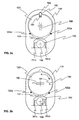
- FIG. 2a The operation of the lock according to the invention when turning the key 180 is seen in figures 2a-2d .
- Fig. 2a the lock is in the basic state.
- the cylindrical cavity made in the lock body 110, in which the lock cylinder 120 has been centrically placed, is also seen in Fig. 2a .
- the rest cavity 192 of the detent bar 190, into which the spring 191 presses the detent bar 190 in the rest position of the lock, is seen in the upper part of the lock body.
- the rest cavity 192 has been formed such that by turning the lock cylinder 120 by the key 180 lightly, the detent bar 192 is removed from the rest cavity 192.
- the key 180 In the middle of the lock cylinder 120 there is seen the key 180, which can be entirely smooth without mechanical coding in the solution according to the invention.
- a mechanical projection, detent 111 is seen on the lower part of the cylindrical cavity made in the lock body.
- the detent has been made by two grooves in the direction of the lock cylinder. If the key 180 is not accepted, this detent 111 prevents the movement of the detent bar 190 past it.
- Fig. 2a also shows schematically how one actuator 150 and generator 130 according to the invention have been connected in relation to the lock body 110 and the detent 111.
- the actuator 150 according to the invention has been connected by two springs 151c and 151d to the lock body 110.
- the actuator 150 has also been permanently connected to the upper part of the body of the generator 130, and therefore the turning of the body of the generator 130 in relation to its longitudinal axis also turns the actuator 150.
- Fig. 2b the key has been turned in the lock 100 about 90 degrees in the direction of arrow A.
- the movement of the key turns the electric generator 130, which produces electric energy for identifying the key and considering the acceptance.
- the detent bar 190 presses against the wall of the cavity of the lock body 110 lightly by the force of the spring 191.
- the torque experienced by the electric generator is low during the production of electric energy. Therefore the body of the generator 130 turns in the direction of arrow B only slightly.
- the sensor 122a sends a message on exceeding the angle to the control unit 121.
- the figure also shows a sensor 122b, which functions in systems in which the turning direction of the key 180 is different from that of the examples of figures 2a-2d .
- the control unit 121 at the latest makes the decision on the opening or prevention of the lock.
- Fig. 2c presents a situation in which the lock cylinder 120 has been turned by the key 180 almost 180 degrees in the direction of arrow C.
- the key has not been accepted for opening the lock.
- the control unit performs the switching by which the torque experienced by the generator 130 is minimized. It can be done, for example, by disconnecting (opening) the feed lines coming to the control unit 121. As a result of this, the body of the generator 130 turns only for a small distance in the direction of arrow D, because the torque transmitted by the generator is small.
- Fig. 2d shows a situation in which the identifier 181 of the key 180 has been accepted. Having accepted the identifier of the key 180, the control unit 121 electrically changes the coupling that loads the generator 130 by shorting the feed lines 122 coming from the generator, for example. This procedure considerably increases the torque transmitted by the generator 130 when the key 180 is turned in the direction of arrow E. As a result of that, the body of the generator 130 turns substantially in the direction of arrow F. Because the actuator 150 has been permanently connected to the body of the generator 130, the position of the actuator 150 also changes accordingly. When the actuator 150 turns sufficiently, the force exerted by the actuator 150 to the detent bar 190 is higher than the force of spring 191 in the opposite direction at the front edge of the detent 111. Then the actuator 150 can guide the detent bar 190 past the front edge of the detent 111.
- the turning of the key 180 can be continued further.
- the prior art mechanical bolt of the lock is moved by the key 180, whereby the lock (not shown in the figures) connected to the shaft 101 can be opened mechanically.
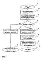
- Fig. 3 shows the main steps of the locking method according to the invention as an exemplary flow chart.
- step 31 the key is inserted in the lock.
- the key is turned in step 32, whereby the electric generator, which is powered by the movement of the lock cylinder, produces electric current to the control unit of the lock.
- the control unit can read the content of the identifier unit of the key, step 33.
- the information contained by the identifier unit can be encrypted by some prior art method.
- step 34 the control unit accepts or rejects the key on the basis of the identifier information it has read. If the key is not accepted, the control unit sees to it that the torque transmitted by the electric generator is minimized in step 39. In that case, the electric generator, which has been fastened as turnable in relation to its longitudinal axis, does not turn the actuator according to the invention to such a position that the detent bar of the lock cylinder could pass the detent in the lock body. Thus it is found in step 40 that the lock cannot be opened by the key in question.
- the control unit changes the load of the generator in step 35.
- the change of the load maximises the torque transmitted by the generator, whereby turning the key in the lock also turns the body of the electric generator in relation to its longitudinal axis, step 36.
- at least one actuator according to the invention is set in a position in which the detent bar can pass the front edge of the detent 111 belonging to the lock body.
- the lock can be opened by turning the key further in the same direction.
- the mechanical bolt in the lock can be moved to the open position by turning the key, step 37.
- the end result is an opened lock, step 38.
- the electric control unit may also comprise various inputs and outputs and a connection of the programming port.
- the change of torque according to the invention can also be implemented at any point of the chain of power transmission from the key to the generator.
- the inventive idea can be applied in many different ways within the scope defined by the attached claims.
Landscapes
- Physics & Mathematics (AREA)
- Electromagnetism (AREA)
- Lock And Its Accessories (AREA)
- Electrotherapy Devices (AREA)
- Paper (AREA)
Abstract
Description
- The invention relates to an electromechanical programmable lock and its operating system.
- A locking system based on a programmable, electronic key can be implemented either as centralized or decentralized or as a combination thereof.
- A centralized system consists of an electricity supply and telecommunications network, electrically operated lock bodies, electronic key reading devices, electronic keys, generally containing only a code, programmable control units and backup batteries. A centralized system provides good properties, but is expensive to implement especially in an old building, in which no provision has been made for the cabling required by the system.
- A decentralized system generally makes an independent opening decision in the lock control unit on the basis of information programmed in the key. The power supply of the system has typically been implemented by a power source feeding the lock control unit and/or a backup battery. The power supply of a decentralized system can also be implemented by a battery in the key. The maintenance of the batteries of the locks and keys is problematic, because the draining of the batteries prevents opening the lock or they leave the lock in the open position.
- There are also known locks in which the identification of the key and the opening/closing of the lock is carried out either partly or entirely electrically. In such locking systems, the key includes a memory element, which can be read and identified by the reading circuit in the lock. If the lock recognizes the electric identifier of the key, the lock opens either by turning the key set in the lock or by the operation of an electric opening mechanism. One such solution has been presented in the patent
US 6 331 812 , in which a locking code has been saved in the key. The key also includes a small battery, by which the key code can be sent to the lock. Another exemplary solution of the use of an electric key identifier is known from the applicationWO 00/68536 - An electric locking arrangement, which is entirely independent of an external source of electric energy, is known from the following publications, for example. The publication
WO 81/02603 - Publication
DE 19918817 discloses a procedure, in which the key has been provided with an arrangement creating electricity. The electricity is produced by means of a mass moving in the key, which operates an electric generator. The mass in the key moves when the person is moving, thereby creating a small electric current. The electricity produced is loaded to a battery in the key. The energy of the battery is used in sending the code of the key to the lock. - A lock, which is independent of an external energy source and at least partly electrically operated, can also be implemented by using the piezoelectric phenomenon. An arrangement, in which piezoelectric elements have been installed in the body of the lock, is known from the patent
US 6 437 684 . Inserting the key in the lock and turning it in the lock creates a deformation in the piezoelements, which creates an electric current. This current is utilized in the management of the locking. - Two different piezoelectric lock solutions are known from the published application
FR 276 4625 US 5 265 452 A . - The objective of the invention is to provide a new lock and locking method, by which an electromechanic, programmable lock system can be implemented without a separate, electric power source.
- The objectives of the invention are achieved by a lock arrangement, in which mechanical power transmission has been arranged from a turnable lock cylinder to an electric generator turnably fastened to the lock body, the turning angle of which depends on the torque transmitted by it. When the key is turned, electric current is first produced by an electric generator to the electric key identification system of the lock. Then the electrical load of the generator does not produce a high torque. If the key is identified and accepted to be used for opening the lock, the output arrangement of the generator is changed so that the torque transmitted by the generator increases strongly. Turning the key then also causes the turning of the body of the electric generator, as a result of which the mechanical detent is removed from the opening path of the lock. After this, the lock opens fully mechanically by turning the key further.
- The invention has the advantage that an electric lock system can be implemented without a separate electric actuator and the storage of electric energy required by it.
- In addition, the invention has the advantage that electric identification can be used in the lock, which enables the use of more versatile protection arrangements than a conventional mechanical locking system.
- A further advantage of the invention is the fact that electric energy is required only for the identification and acceptance of the key and the coupling arrangements of the terminals of the generator.
- Yet another advantage of the invention is easy electric programmability of the lock and the key, which enables changing the locking system easily.
- An additional advantage of the invention is the fact that the key bit can be smooth, or only one projection or groove is required in it to enable drawing the door open by the key.
- Another additional advantage of the invention is the fact that the lock can be opened mechanically by turning the key, and no electric energy is required for opening it.
- The electromechanical lock according to the invention is characterized in that the electric energy required by the electric identification has been produced from the movement of the key by an electromagnetic generator, and that the difference between the torque transmitted by the loaded and unloaded electromagnetic generator has been arranged either to open the lock or to bring it to the blocking state.
- The electromechanical locking method according to the invention is characterized in that the electric energy required by the electric identification of the key is produced by the movement of the key by means of an electromagnetic generator, and that the difference between the torque of the loaded and unloaded electromagnetic generator is used either to open the lock or to bring it to the blocking state.
- Some preferred embodiments of the invention are presented in the dependent claims.
- The basic idea of the invention is the following: Electrical identification and acceptance of the key and mechanical opening motion of the lock bolt are both utilized in the lock. The key is identified and accepted electrically, but the motion of the bolt is achieved mechanically by turning the key. The key turns sufficiently for moving the bolt only if the key has been identified. Alternatively, an unaccepted key turns freely around in the lock body without a mechanical connection to the lock bolt. The electric energy required for the identification and acceptance is produced in the lock by an electromagnetic generator, the rotor of which is turned by turning the key. The motion of the key to the rotor of the generator is transmitted from the lock cylinder by a gear system. The body of a direct-current generator has been installed in the lock body so that the direct-current generator can be turned around its longitudinal axis. If the control unit of the lock finds that the key turned in the lock is not allowed to open the lock, the control unit changes the coupling of the output of the direct-current generator in a way that the torque of the rotor is minimized. For example, the terminals of the generator can be disconnected. In this case, the body of the generator does not turn from its rest position, and the detent bar of the lock cylinder collides with the detent in the lock body. Alternatively, the key turns round in the lock without a mechanical connection to the bolt.
- The situation changes if the control unit of the lock finds that the key turned in the lock is such that the lock may be opened by it. In this case, the control unit of the lock changes the coupling of the output of the direct-current generator in a way that the torque of the rotor increases strongly. The output of the generator can be shorted, for example. In this case, the torque produced by the key and directed to the generator grows so high that it exceeds the moment caused by the fastening of the body of the direct-current generator, which resists the turning of the body of the direct-current generator. When the key is turned further, the body of the direct-current generator then turns so that it moves the detent bar in the lock to a position in which it does not prevent turning the lock cylinder by the key to a position in which the bolt is drawn into the lock. Alternatively in the arrangement according to the invention, the key is connected to a freely turning lock cylinder, which is further connected to the bolt.
- In the following, the invention will be described in more detail. Reference will be made to the accompanying figures, in which
- Figure 1
- shows a longitudinal section of a lock according to the invention as an example;
- Figure 2a
- shows a cross-section of the lock of
Fig. 1 in the starting position as an example; - Figure 2b
- shows, as an example, the lock of
Fig. 1 when electric energy is produced by the key for identification and acceptance; - Figure 2c
- shows, as an example, the lock of
Fig. 1 in the closing position, in which the key has not been identified; - Figure 2d
- shows, as an example, the lock of
Fig. 1 in the opening position, in which the key has been identified; and - Figure 3
- which shows the main steps of the locking method according to the invention as an exemplary flow chart.
-
Fig. 1 shows anexemplary lock arrangement 100, in which the invention can be applied. The key 180 belonging to the lock comprises anelectrical identification unit 181. The key 180 and theelectrical identification unit 181 belonging to it can be programmed by some prior art system. The operation of the invention only requires that the information comprised by theidentification unit 181 in the key 180 can be read from the key by some electrical system. The information of theidentification unit 181 preferably comprises the identification code of the key 180, an encryption key and user group information. For safety of use, the information has been encrypted by some prior art encryption technique. - The
control unit 121 belonging to thelock 100 can read the information contained by theidentification unit 181. The reading can be carried out either wirelessly or via a wired contact, like in the example ofFig. 1 bysignal conductors slide contacts 125. Wireless reading is possible e.g. by the RFID (Radio Frequency Identification) technology, in which thedevice 121 of theidentifier unit 181 carrying out the reading wirelessly transmits to the circuit being read a sufficient amount of electric energy for reading the identifier wirelessly. Thecontrol unit 121 may also comprise anexternal connection 123, through which the information or the state of the control unit can be read or changed. Theexternal connection 123 is preferably located on the side of the door in the object to be protected to which access is only by an accepted key. - In
Fig. 1 ,number 110 denotes a lock body, which is preferably cylindrical. Thelock body 110 has been provided with a cylindrical inner cavity, in which thelock cylinder 120 can turn around itslongitudinal axis 101 by the force of the key 180. Therest cavity 192 of thedetent bar 190 has also been made in thelock body 110. When the lock is in the basic position, thedetent bar 190 is pressed to therest cavity 192 by the force of thesprings 191 a and 192b. Then the lock can be said to be in the basic position. - Cavities for the electric generator according to the invention and the locking
actuators lock body 110. Amechanical gear system 140 has also been permanently connected to theelectric generator 130, which is preferably a permanent magnet generator. They have preferably been placed concentrically on thesame shaft 102. Theelectric generator 130 can be implemented by a Faulhaber generator 0816006F, for example, and thegear system 140 by a gear system 08/1 of the same manufacturer, which has a transformation ratio of the order of 1:60. This arrangement can produce approx. 1 mJ of energy, which is sufficient for carrying out the identification and acceptance. Thelock cylinder 120 and thegear system 140 have preferably been connected to each other bytoothed gear wheels lock cylinder 120 is thus transmitted to theshaft 102 of thegenerator 130 in the opposite direction. This rotatory motion, which has an opposite direction in relation to the lock cylinder, is utilized in the opening method of the locking according to the invention. - In the example of
Fig. 1 ,actuators gear system detent bar 190 can be directed past thedetent 111 on the lower part of thelock body 110 by theactuators detent 111 has advantageously been made by shaping in the cavity of the lock cylinder in thelock body 110 at least one lock groove, to which thedetent bar 190 can get stuck. Turnable connection of actuators 150a and 150b can be implemented bysprings springs - The
lock 100 also includes acontrol unit 121. In the example ofFig. 1 , it has been placed in thelock body 110, but it can naturally also be located in thelock cylinder 120. However, this alternative embodiment is more complicated than the solution mentioned above, because in this solution it is also necessary to arrange the transfer of energy from thelock body 110 to therotating lock cylinder 120. In the example ofFig. 1 , the electric energy is fed from thegenerator 130 as follows. Thefirst feed lines 131, which are permanently connected to thecontrol unit 121 of the lock, start from thegenerator 130. When the key 180 is turned, advantageously about 90 degrees from the starting position, the electric energy created is thus transferred from thegenerator 130 to the inputs of thecontrol unit 121. In the first step of opening the lock, electricity is used for reading the information comprised by theidentifier unit 181 of the key 180. When the key has been turned about 120 degrees, the signal of thesensor 122 in thebody 110 of the lock is directed along theconnection 127 to thecontrol unit 121. Then thecontrol unit 121 must make the decision on allowing or preventing the opening of the lock. In an advantageous embodiment of the invention, the current of the electromagnetic generator can also be used to load a capacitor (not shown inFig. 1 ), the coupling of which to thefeed lines 131 coming from the electromagnetic generator can be changed. The loading transmitted by the electromagnetic generator can be regulated by the coupling of the capacitor. - If the identification of the key is accepted, the
control unit 121 changes the coupling connected to thefeed lines 131 in such a way that the change of the coupling considerably increases the torque measurable from theshaft 102 of the electric generator. This can be done, for example, by shorting thefeed lines 131 coming to thecontrol unit 121. It is also possible to feed a current in the opposite direction from thecontrol unit 121 back to thegenerator 130 from a capacitor connected in the reverse direction, for example, in order to increase the torque. - When the torque transmitted by the
generator 130 increases, it causes the body of thewhole generator 130 to turn in spite of the resisting force of thesprings actuators detent bar 190 past thedetent 111, and the lock can be opened by turning the key 180 further. - If the key 180 is not identified or accepted before the turning angle of the key exceeds about 120 degrees, the
control unit 121 advantageously disconnects thefeed lines 131 coming from theelectric generator 130. Then the torque transmitted by theelectric generator 130 is minimized and remains so small that the body of the electric generator does not turn sufficiently to enable theactuators detent bar 190 past thedetent 111. Then the lock cannot be opened mechanically by the key. If thecontrol unit 121 also comprises a capacitor, it can be connected to thefeed lines 131 in the forward direction in order to reduce the torque transmitted by the electromagnetic generator. - The operation of the lock according to the invention when turning the key 180 is seen in
figures 2a-2d . InFig. 2a , the lock is in the basic state. The cylindrical cavity made in thelock body 110, in which thelock cylinder 120 has been centrically placed, is also seen inFig. 2a . Therest cavity 192 of thedetent bar 190, into which thespring 191 presses thedetent bar 190 in the rest position of the lock, is seen in the upper part of the lock body. Therest cavity 192 has been formed such that by turning thelock cylinder 120 by the key 180 lightly, thedetent bar 192 is removed from therest cavity 192. In the middle of thelock cylinder 120 there is seen the key 180, which can be entirely smooth without mechanical coding in the solution according to the invention. - In
Fig. 2a , a mechanical projection,detent 111, is seen on the lower part of the cylindrical cavity made in the lock body. In the example ofFig. 2a , the detent has been made by two grooves in the direction of the lock cylinder. If the key 180 is not accepted, thisdetent 111 prevents the movement of thedetent bar 190 past it.Fig. 2a also shows schematically how oneactuator 150 andgenerator 130 according to the invention have been connected in relation to thelock body 110 and thedetent 111. In the example ofFig. 2a , theactuator 150 according to the invention has been connected by twosprings lock body 110. Theactuator 150 has also been permanently connected to the upper part of the body of thegenerator 130, and therefore the turning of the body of thegenerator 130 in relation to its longitudinal axis also turns theactuator 150. - In
Fig. 2b , the key has been turned in thelock 100 about 90 degrees in the direction of arrow A. The movement of the key turns theelectric generator 130, which produces electric energy for identifying the key and considering the acceptance. Thedetent bar 190 presses against the wall of the cavity of thelock body 110 lightly by the force of thespring 191. The torque experienced by the electric generator is low during the production of electric energy. Therefore the body of thegenerator 130 turns in the direction of arrow B only slightly. With regard to the invention, it is advantageous that the turning movement of the key 180 turns the body of thegenerator 130 in a different direction than thelock cylinder 120. When the key is turned further, the turning angle of 120 degrees is exceeded, in which case thesensor 122a sends a message on exceeding the angle to thecontrol unit 121. The figure also shows asensor 122b, which functions in systems in which the turning direction of the key 180 is different from that of the examples offigures 2a-2d . After this, thecontrol unit 121 at the latest makes the decision on the opening or prevention of the lock. -
Fig. 2c presents a situation in which thelock cylinder 120 has been turned by the key 180 almost 180 degrees in the direction of arrow C. However, in the case ofFig. 2c , the key has not been accepted for opening the lock. Then the control unit performs the switching by which the torque experienced by thegenerator 130 is minimized. It can be done, for example, by disconnecting (opening) the feed lines coming to thecontrol unit 121. As a result of this, the body of thegenerator 130 turns only for a small distance in the direction of arrow D, because the torque transmitted by the generator is small. This small turn of the body of thegenerator 130 cannot turn theactuator 150 to such a position that thedetent bar 190 would pass thedetent 111 belonging to the lock body, but thespring 191 presses thedetent bar 190 against the front edge of thedetent 111. Thus the movement of the key 180 stops at thedetent 111 and thelock 100 cannot be opened. -
Fig. 2d shows a situation in which theidentifier 181 of the key 180 has been accepted. Having accepted the identifier of the key 180, thecontrol unit 121 electrically changes the coupling that loads thegenerator 130 by shorting thefeed lines 122 coming from the generator, for example. This procedure considerably increases the torque transmitted by thegenerator 130 when the key 180 is turned in the direction of arrow E. As a result of that, the body of thegenerator 130 turns substantially in the direction of arrow F. Because theactuator 150 has been permanently connected to the body of thegenerator 130, the position of theactuator 150 also changes accordingly. When theactuator 150 turns sufficiently, the force exerted by theactuator 150 to thedetent bar 190 is higher than the force ofspring 191 in the opposite direction at the front edge of thedetent 111. Then the actuator 150 can guide thedetent bar 190 past the front edge of thedetent 111. - Because the
detent 111 has been passed, the turning of the key 180 can be continued further. After thedetent 111, the prior art mechanical bolt of the lock is moved by the key 180, whereby the lock (not shown in the figures) connected to theshaft 101 can be opened mechanically. -
Fig. 3 shows the main steps of the locking method according to the invention as an exemplary flow chart. Instep 31, the key is inserted in the lock. The key is turned instep 32, whereby the electric generator, which is powered by the movement of the lock cylinder, produces electric current to the control unit of the lock. By the electricity produced by the generator, the control unit can read the content of the identifier unit of the key,step 33. The information contained by the identifier unit can be encrypted by some prior art method. - In
step 34, the control unit accepts or rejects the key on the basis of the identifier information it has read. If the key is not accepted, the control unit sees to it that the torque transmitted by the electric generator is minimized instep 39. In that case, the electric generator, which has been fastened as turnable in relation to its longitudinal axis, does not turn the actuator according to the invention to such a position that the detent bar of the lock cylinder could pass the detent in the lock body. Thus it is found instep 40 that the lock cannot be opened by the key in question. - If the key is accepted in
step 34, the control unit changes the load of the generator instep 35. The change of the load maximises the torque transmitted by the generator, whereby turning the key in the lock also turns the body of the electric generator in relation to its longitudinal axis,step 36. As a result of the turning of the body of the electric generator, at least one actuator according to the invention is set in a position in which the detent bar can pass the front edge of thedetent 111 belonging to the lock body. After this, the lock can be opened by turning the key further in the same direction. Then the mechanical bolt in the lock can be moved to the open position by turning the key,step 37. The end result is an opened lock,step 38. - Some preferred embodiments of the lock and operating system of the lock according to the invention have been described above. The invention is not limited to the solutions described above. For example, the electric control unit may also comprise various inputs and outputs and a connection of the programming port. The change of torque according to the invention can also be implemented at any point of the chain of power transmission from the key to the generator. In addition, the inventive idea can be applied in many different ways within the scope defined by the attached claims.
Claims (14)
- An electromechanical lock (100), which comprises means for electrically reading and checking (121) the information of an identifier unit (181) of a key (180) and means for mechanically opening the lock by turning the key in the lock, if the key has the opening right, and in which lock the electric energy required by the electrical identification has been produced from the movement of the key (180) by an electromagnetic generator (130), characterized in that- a capacitor has been arranged to be loaded by the key movement before the opening decision- the identification of the key has been arranged to change an electric coupling of the generator (130) by coupling the outputs of the capacitor to the electromagnetic generator (130) either in the forward or reverse direction depending on the opening decision- the change of the electric coupling of the generator (130) has been arranged to change the mechanical load of the generator, which has been arranged to change the position of the generator, and that- the change of the position of the generator (130) caused by the change of the loading of the electromagnetic generator has been arranged to guide the lock open or to the prevention state.
- The electromechanical lock according to Claim 1, characterized in that the means for reading and checking the electrical identifier of the key comprise an electronic control unit (121) in a lock body (110), energy feed lines (131) of the control unit and signal lines (124).
- The electromechanical lock according to Claim 1, characterized in that the means for reading and checking the electric identifier of the key comprise an electronic control unit (121) in a lock cylinder (120), energy feed lines (131) of the control unit and signal lines (124).
- The electromechanical lock according to Claim 2 or 3, characterized in that the torque transmitted by the electric generator has been arranged to be increased for enabling the opening of the lock by shorting the feed lines coming from the electric generator (130) to the control unit (121) in the control unit (121) after accepting the key.
- The electromechanical lock according to Claim 4, characterized in that the growth of the torque transmitted by the electric generator (130) has been arranged to turn the body of the electric generator to a position in which it further turns at least one actuator (150) fastened to the body of the electric generator to a position in which the actuator (150) has been arranged to guide a spring-loaded (191 a, 191 b) detent bar (190) past a detent (111) in the lock body (110) for allowing the opening of the lock.
- The electromechanical lock according to Claim 1, characterized in that an opening right of the key (180) has been arranged to be installed in the control unit (121) through an external input connection (123) belonging to it.
- The electromechanical lock according to Claim 1, characterized in that the movement of the key (180) for producing electric energy has been arranged to be transmitted from the lock cylinder (120) to the electric generator by means of a gear wheel (171) in the lock cylinder and a gear system (140) connected on the shaft of the electric generator (130) and a gear wheel (172) connected to the gear system.
- An operating method of an electromechanical lock, in which method- the information of an identifier unit (181) of a key is read electrically (32, 33, 33)- after the acceptance of an opening right, the lock is opened mechanically by turning the key (37), and in which- the electric energy required by the electric identification of the key is produced by the movement of the key by means of an electromagnetic generator (130),characterized in that- an electric coupling of the generator (130) is changed by the identification of the key- the mechanical load of the generator (130), by which the position of the generator is changed, is changed by the change of the electric coupling of the generator, and that- the lock is brought open or to the prevention state by a change of the position of the generator (130) caused by a change of the loading of the electromagnetic generator.
- The operating method according to Claim 8, characterized in that a capacitor loaded before the opening decision is used for the change of the loading of the generator (130), and this capacitor is coupled to the electromagnetic generator either in a forward or reverse direction depending on the opening decision.
- The operating method according to Claim 8, characterized in that the information of an electric identifier unit (181) of the key is read and accepted by an electronic control unit (121) in a lock body (110).
- The operating method according to Claim 8, characterized in that the information of an electric identifier unit (181) of the key (180) is read and accepted by an electronic control unit (121) in a lock cylinder (120).
- The operating method according to Claim 10 or 11, characterized in that the torque transmitted by the electric generator (130) is increased for enabling the opening of the lock by shorting feed lines coming from the generator (130) to the control unit (121) in the control unit (121) after accepting the key.
- The operating method according to Claim 12, characterized in that the growth of the torque transmitted by the electric generator (130) turns the body of the electric generator to a position in which it further turns the at least one actuator (150) fastened to the body of the electric generator to a position in which the actuator (150) guides a detent bar (190) of the lock past a detent (111) in the lock body (110) for allowing the opening of the lock.
- The operating method according to Claim 8, characterized in that for producing electric energy, the turning movement of the key (180) is transmitted from the lock cylinder (120) to the electric generator by means of a gear wheel (171) in the lock cylinder and a gear system (140) connected on a shaft of the electric generator (130) and a gear wheel (172) connected to the gear system.
Applications Claiming Priority (2)
| Application Number | Priority Date | Filing Date | Title |
|---|---|---|---|
| FI20041002A FI116914B (en) | 2004-07-19 | 2004-07-19 | Electrical mechanical lock and its use procedure |
| PCT/FI2005/050225 WO2006008340A1 (en) | 2004-07-19 | 2005-06-21 | Electromechanical programmable lock and its operating system |
Publications (2)
| Publication Number | Publication Date |
|---|---|
| EP1786998A1 EP1786998A1 (en) | 2007-05-23 |
| EP1786998B1 true EP1786998B1 (en) | 2010-03-10 |
Family
ID=32749219
Family Applications (1)
| Application Number | Title | Priority Date | Filing Date |
|---|---|---|---|
| EP05756278A Expired - Lifetime EP1786998B1 (en) | 2004-07-19 | 2005-06-21 | Electromechanical programmable lock and its operating system |
Country Status (5)
| Country | Link |
|---|---|
| EP (1) | EP1786998B1 (en) |
| AT (1) | ATE460548T1 (en) |
| DE (1) | DE602005019894D1 (en) |
| FI (1) | FI116914B (en) |
| WO (1) | WO2006008340A1 (en) |
Cited By (1)
| Publication number | Priority date | Publication date | Assignee | Title |
|---|---|---|---|---|
| WO2025125711A1 (en) * | 2023-12-11 | 2025-06-19 | Iloq Oy | Method and means for multi access mode lock system |
Families Citing this family (5)
| Publication number | Priority date | Publication date | Assignee | Title |
|---|---|---|---|---|
| EP2354389B1 (en) * | 2010-01-15 | 2012-09-19 | iLoq Oy | Electromechanical lock |
| US9704316B2 (en) | 2013-09-10 | 2017-07-11 | Gregory Paul Kirkjan | Contactless electronic access control system |
| LT3607159T (en) * | 2017-04-04 | 2021-10-11 | Abloy Oy | Cylinder lock |
| CN110469203B (en) * | 2019-08-23 | 2024-01-30 | 南宁学院 | Finance-specific delayed closing lock |
| US11574513B2 (en) | 2020-03-31 | 2023-02-07 | Lockfob, Llc | Electronic access control |
Family Cites Families (1)
| Publication number | Priority date | Publication date | Assignee | Title |
|---|---|---|---|---|
| US5265452A (en) * | 1991-09-20 | 1993-11-30 | Mas-Hamilton Group | Bolt lock bolt retractor mechanism |
-
2004
- 2004-07-19 FI FI20041002A patent/FI116914B/en active IP Right Grant
-
2005
- 2005-06-21 EP EP05756278A patent/EP1786998B1/en not_active Expired - Lifetime
- 2005-06-21 AT AT05756278T patent/ATE460548T1/en not_active IP Right Cessation
- 2005-06-21 WO PCT/FI2005/050225 patent/WO2006008340A1/en not_active Ceased
- 2005-06-21 DE DE602005019894T patent/DE602005019894D1/en not_active Expired - Lifetime
Cited By (1)
| Publication number | Priority date | Publication date | Assignee | Title |
|---|---|---|---|---|
| WO2025125711A1 (en) * | 2023-12-11 | 2025-06-19 | Iloq Oy | Method and means for multi access mode lock system |
Also Published As
| Publication number | Publication date |
|---|---|
| FI20041002L (en) | 2006-01-20 |
| EP1786998A1 (en) | 2007-05-23 |
| WO2006008340A8 (en) | 2006-04-13 |
| DE602005019894D1 (en) | 2010-04-22 |
| ATE460548T1 (en) | 2010-03-15 |
| WO2006008340A1 (en) | 2006-01-26 |
| FI116914B (en) | 2006-03-31 |
| FI20041002A0 (en) | 2004-07-19 |
Similar Documents
| Publication | Publication Date | Title |
|---|---|---|
| CN101778985B (en) | Electromechanical lock | |
| US6668606B1 (en) | Electronic token lock core | |
| CA2729007C (en) | Electromechanical lock and its key | |
| US20110277520A1 (en) | Electronic device for a mechanical blocking. | |
| KR100989001B1 (en) | Door cylinder lock | |
| US5628217A (en) | Electronic-mechanical locking cylinders | |
| EP2017412B1 (en) | Electromechanical lock | |
| EP1492930B1 (en) | Electro-mechanical cylinder lock-key combination with optical code | |
| US5423198A (en) | Dual control mode lock | |
| WO2006003661A2 (en) | Intelligent interactive lock and locking system | |
| US20240218701A1 (en) | Strike linkage and in-wall receiver | |
| EP1904702B1 (en) | Electromechanical lock device | |
| WO2013057498A1 (en) | Lock device | |
| EP3543442B1 (en) | Release mechanism, energy harvesting arrangement and electronic locking system | |
| EP1786998A1 (en) | Electromechanical programmable lock and its operating system | |
| WO2009010637A1 (en) | Electromechanical lock and key | |
| KR20240017782A (en) | Half-cylinder lock | |
| WO2009028991A2 (en) | Mechanically locking or blocking electronic device | |
| US6603222B2 (en) | Locking device for lock | |
| EP3263810B1 (en) | History management system of electronic locking apparatus | |
| WO1999061732A1 (en) | An electronic lock | |
| CZ2007368A3 (en) | Electromechanical cylinder-type lock |
Legal Events
| Date | Code | Title | Description |
|---|---|---|---|
| PUAI | Public reference made under article 153(3) epc to a published international application that has entered the european phase |
Free format text: ORIGINAL CODE: 0009012 |
|
| 17P | Request for examination filed |
Effective date: 20070214 |
|
| AK | Designated contracting states |
Kind code of ref document: A1 Designated state(s): AT BE BG CH CY CZ DE DK EE ES FI FR GB GR HU IE IS IT LI LT LU MC NL PL PT RO SE SI SK TR |
|
| DAX | Request for extension of the european patent (deleted) | ||
| GRAP | Despatch of communication of intention to grant a patent |
Free format text: ORIGINAL CODE: EPIDOSNIGR1 |
|
| GRAS | Grant fee paid |
Free format text: ORIGINAL CODE: EPIDOSNIGR3 |
|
| RAP1 | Party data changed (applicant data changed or rights of an application transferred) |
Owner name: ILOQ OY |
|
| GRAA | (expected) grant |
Free format text: ORIGINAL CODE: 0009210 |
|
| AK | Designated contracting states |
Kind code of ref document: B1 Designated state(s): AT BE BG CH CY CZ DE DK EE ES FI FR GB GR HU IE IS IT LI LT LU MC NL PL PT RO SE SI SK TR |
|
| REG | Reference to a national code |
Ref country code: GB Ref legal event code: FG4D |
|
| REG | Reference to a national code |
Ref country code: CH Ref legal event code: EP |
|
| REG | Reference to a national code |
Ref country code: IE Ref legal event code: FG4D |
|
| REF | Corresponds to: |
Ref document number: 602005019894 Country of ref document: DE Date of ref document: 20100422 Kind code of ref document: P |
|
| REG | Reference to a national code |
Ref country code: NL Ref legal event code: VDEP Effective date: 20100310 |
|
| PG25 | Lapsed in a contracting state [announced via postgrant information from national office to epo] |
Ref country code: LT Free format text: LAPSE BECAUSE OF FAILURE TO SUBMIT A TRANSLATION OF THE DESCRIPTION OR TO PAY THE FEE WITHIN THE PRESCRIBED TIME-LIMIT Effective date: 20100310 |
|
| LTIE | Lt: invalidation of european patent or patent extension |
Effective date: 20100310 |
|
| PG25 | Lapsed in a contracting state [announced via postgrant information from national office to epo] |
Ref country code: SI Free format text: LAPSE BECAUSE OF FAILURE TO SUBMIT A TRANSLATION OF THE DESCRIPTION OR TO PAY THE FEE WITHIN THE PRESCRIBED TIME-LIMIT Effective date: 20100310 Ref country code: PL Free format text: LAPSE BECAUSE OF FAILURE TO SUBMIT A TRANSLATION OF THE DESCRIPTION OR TO PAY THE FEE WITHIN THE PRESCRIBED TIME-LIMIT Effective date: 20100310 Ref country code: FI Free format text: LAPSE BECAUSE OF FAILURE TO SUBMIT A TRANSLATION OF THE DESCRIPTION OR TO PAY THE FEE WITHIN THE PRESCRIBED TIME-LIMIT Effective date: 20100310 Ref country code: AT Free format text: LAPSE BECAUSE OF FAILURE TO SUBMIT A TRANSLATION OF THE DESCRIPTION OR TO PAY THE FEE WITHIN THE PRESCRIBED TIME-LIMIT Effective date: 20100310 |
|
| PG25 | Lapsed in a contracting state [announced via postgrant information from national office to epo] |
Ref country code: GR Free format text: LAPSE BECAUSE OF FAILURE TO SUBMIT A TRANSLATION OF THE DESCRIPTION OR TO PAY THE FEE WITHIN THE PRESCRIBED TIME-LIMIT Effective date: 20100611 Ref country code: ES Free format text: LAPSE BECAUSE OF FAILURE TO SUBMIT A TRANSLATION OF THE DESCRIPTION OR TO PAY THE FEE WITHIN THE PRESCRIBED TIME-LIMIT Effective date: 20100621 Ref country code: EE Free format text: LAPSE BECAUSE OF FAILURE TO SUBMIT A TRANSLATION OF THE DESCRIPTION OR TO PAY THE FEE WITHIN THE PRESCRIBED TIME-LIMIT Effective date: 20100310 Ref country code: SE Free format text: LAPSE BECAUSE OF FAILURE TO SUBMIT A TRANSLATION OF THE DESCRIPTION OR TO PAY THE FEE WITHIN THE PRESCRIBED TIME-LIMIT Effective date: 20100310 Ref country code: CY Free format text: LAPSE BECAUSE OF FAILURE TO SUBMIT A TRANSLATION OF THE DESCRIPTION OR TO PAY THE FEE WITHIN THE PRESCRIBED TIME-LIMIT Effective date: 20100310 Ref country code: BE Free format text: LAPSE BECAUSE OF FAILURE TO SUBMIT A TRANSLATION OF THE DESCRIPTION OR TO PAY THE FEE WITHIN THE PRESCRIBED TIME-LIMIT Effective date: 20100310 Ref country code: NL Free format text: LAPSE BECAUSE OF FAILURE TO SUBMIT A TRANSLATION OF THE DESCRIPTION OR TO PAY THE FEE WITHIN THE PRESCRIBED TIME-LIMIT Effective date: 20100310 Ref country code: RO Free format text: LAPSE BECAUSE OF FAILURE TO SUBMIT A TRANSLATION OF THE DESCRIPTION OR TO PAY THE FEE WITHIN THE PRESCRIBED TIME-LIMIT Effective date: 20100310 |
|
| PG25 | Lapsed in a contracting state [announced via postgrant information from national office to epo] |
Ref country code: BG Free format text: LAPSE BECAUSE OF FAILURE TO SUBMIT A TRANSLATION OF THE DESCRIPTION OR TO PAY THE FEE WITHIN THE PRESCRIBED TIME-LIMIT Effective date: 20100610 Ref country code: IS Free format text: LAPSE BECAUSE OF FAILURE TO SUBMIT A TRANSLATION OF THE DESCRIPTION OR TO PAY THE FEE WITHIN THE PRESCRIBED TIME-LIMIT Effective date: 20100710 Ref country code: SK Free format text: LAPSE BECAUSE OF FAILURE TO SUBMIT A TRANSLATION OF THE DESCRIPTION OR TO PAY THE FEE WITHIN THE PRESCRIBED TIME-LIMIT Effective date: 20100310 Ref country code: CZ Free format text: LAPSE BECAUSE OF FAILURE TO SUBMIT A TRANSLATION OF THE DESCRIPTION OR TO PAY THE FEE WITHIN THE PRESCRIBED TIME-LIMIT Effective date: 20100310 |
|
| PLBE | No opposition filed within time limit |
Free format text: ORIGINAL CODE: 0009261 |
|
| STAA | Information on the status of an ep patent application or granted ep patent |
Free format text: STATUS: NO OPPOSITION FILED WITHIN TIME LIMIT |
|
| PG25 | Lapsed in a contracting state [announced via postgrant information from national office to epo] |
Ref country code: PT Free format text: LAPSE BECAUSE OF FAILURE TO SUBMIT A TRANSLATION OF THE DESCRIPTION OR TO PAY THE FEE WITHIN THE PRESCRIBED TIME-LIMIT Effective date: 20100712 Ref country code: MC Free format text: LAPSE BECAUSE OF NON-PAYMENT OF DUE FEES Effective date: 20100630 Ref country code: DK Free format text: LAPSE BECAUSE OF FAILURE TO SUBMIT A TRANSLATION OF THE DESCRIPTION OR TO PAY THE FEE WITHIN THE PRESCRIBED TIME-LIMIT Effective date: 20100310 |
|
| REG | Reference to a national code |
Ref country code: CH Ref legal event code: PL |
|
| 26N | No opposition filed |
Effective date: 20101213 |
|
| PG25 | Lapsed in a contracting state [announced via postgrant information from national office to epo] |
Ref country code: IT Free format text: LAPSE BECAUSE OF FAILURE TO SUBMIT A TRANSLATION OF THE DESCRIPTION OR TO PAY THE FEE WITHIN THE PRESCRIBED TIME-LIMIT Effective date: 20100310 |
|
| PG25 | Lapsed in a contracting state [announced via postgrant information from national office to epo] |
Ref country code: IE Free format text: LAPSE BECAUSE OF NON-PAYMENT OF DUE FEES Effective date: 20100621 Ref country code: CH Free format text: LAPSE BECAUSE OF NON-PAYMENT OF DUE FEES Effective date: 20100630 Ref country code: LI Free format text: LAPSE BECAUSE OF NON-PAYMENT OF DUE FEES Effective date: 20100630 |
|
| PG25 | Lapsed in a contracting state [announced via postgrant information from national office to epo] |
Ref country code: HU Free format text: LAPSE BECAUSE OF FAILURE TO SUBMIT A TRANSLATION OF THE DESCRIPTION OR TO PAY THE FEE WITHIN THE PRESCRIBED TIME-LIMIT Effective date: 20100911 Ref country code: LU Free format text: LAPSE BECAUSE OF NON-PAYMENT OF DUE FEES Effective date: 20100621 |
|
| PG25 | Lapsed in a contracting state [announced via postgrant information from national office to epo] |
Ref country code: TR Free format text: LAPSE BECAUSE OF FAILURE TO SUBMIT A TRANSLATION OF THE DESCRIPTION OR TO PAY THE FEE WITHIN THE PRESCRIBED TIME-LIMIT Effective date: 20100310 |
|
| REG | Reference to a national code |
Ref country code: FR Ref legal event code: PLFP Year of fee payment: 12 |
|
| REG | Reference to a national code |
Ref country code: FR Ref legal event code: PLFP Year of fee payment: 13 |
|
| REG | Reference to a national code |
Ref country code: FR Ref legal event code: PLFP Year of fee payment: 14 |
|
| PGFP | Annual fee paid to national office [announced via postgrant information from national office to epo] |
Ref country code: GB Payment date: 20240618 Year of fee payment: 20 |
|
| PGFP | Annual fee paid to national office [announced via postgrant information from national office to epo] |
Ref country code: DE Payment date: 20240612 Year of fee payment: 20 |
|
| PGFP | Annual fee paid to national office [announced via postgrant information from national office to epo] |
Ref country code: FR Payment date: 20240618 Year of fee payment: 20 |
|
| REG | Reference to a national code |
Ref country code: DE Ref legal event code: R071 Ref document number: 602005019894 Country of ref document: DE |
|
| PG25 | Lapsed in a contracting state [announced via postgrant information from national office to epo] |
Ref country code: GB Free format text: LAPSE BECAUSE OF EXPIRATION OF PROTECTION Effective date: 20250620 |
|
| REG | Reference to a national code |
Ref country code: GB Ref legal event code: PE20 Expiry date: 20250620 |