EP1786978B1 - Fascines - Google Patents
Fascines Download PDFInfo
- Publication number
- EP1786978B1 EP1786978B1 EP05776092A EP05776092A EP1786978B1 EP 1786978 B1 EP1786978 B1 EP 1786978B1 EP 05776092 A EP05776092 A EP 05776092A EP 05776092 A EP05776092 A EP 05776092A EP 1786978 B1 EP1786978 B1 EP 1786978B1
- Authority
- EP
- European Patent Office
- Prior art keywords
- fascine
- inflation
- pipes
- fascine according
- chamber
- Prior art date
- Legal status (The legal status is an assumption and is not a legal conclusion. Google has not performed a legal analysis and makes no representation as to the accuracy of the status listed.)
- Expired - Lifetime
Links
Images

Classifications
-
- E—FIXED CONSTRUCTIONS
- E01—CONSTRUCTION OF ROADS, RAILWAYS, OR BRIDGES
- E01D—CONSTRUCTION OF BRIDGES, ELEVATED ROADWAYS OR VIADUCTS; ASSEMBLY OF BRIDGES
- E01D15/00—Movable or portable bridges; Floating bridges
- E01D15/12—Portable or sectional bridges
- E01D15/122—Inflatable or unreelable bridges ; Bridges with main load-supporting structure consisting only of non-rigid elements, e.g. cables
Definitions
- the invention relates to fascines.
- a fascine is used to fill a discontinuity in the ground such as a ditch or gully and provide a passage over such a discontinuity for, for example, vehicles. Fascines are most often used to facilitate the passage of military vehicles.
- One form of fascine uses a plurality of elongate members of generally circular cross section. Examples of fascines are shown in US-A-4566821 where the fascine is formed by a core of cylindrical pipes loosely disposed within a surrounding flexible sleeve formed by similar pipes. Alternatives using pipes are shown in US-A-4312601 and US-A-5215401 .
- US-A-5406662 uses polyethylene tubes and inflatable core members.
- inflatable members in fascines has the advantage that the members have a smaller volume when uninflated and can thus be more easily transported. It is problem, however, that such inflatable members require inflation equipment to inflate them.
- inflation equipment may include a gas source and a valve which when opened inflates the member.
- the inflation equipment is carried on the outside of the member and is thus liable to damage when the inflatable member is deployed, particularly where the ground is hard or rocky. Such equipment can also be damaged when in situ by, for example, the traffic of vehicles over the fascine.
- a fascine comprises an assembly of elongate members, at least one member including an inflatable chamber and an inflation system for inflating said chamber, characterised in that said inflation system is located within said chamber.
- an inflatable member with an inflation chamber that defines a hollow tube.
- a hollow tube has the advantage of lower inflated volume over a cylindrical inflation chamber and allows easy passage through the tube of flowing water.
- the plurality of elongate members forming a fascine are capable of moving relative to one another and tend to form themselves in an arrangement where the depression is filled providing a generally level upper surface that allows a passage to be made across the fascine. It is plainly advantageous that the surface providing the passage is as level as possible.
- the fascine comprises a plurality of larger diameter inflated pipes 10 and a plurality of smaller diameter inflated tubes 11.
- the larger diameter inflated pipes 10 fill the lower portion of a gully 12 while the smaller diameter inflated tubes 11 overlie the larger diameter inflated pipes 10 to form a passage across the gully 12.
- each pipe 10 is elongate and is formed from a sheet of drop-thread fabric of the kind shown in Figures 3 and 4 .
- the fabric comprises a first textile layer 13 interconnected to a second textile layer 14 by a plurality of drop-threads shown schematically at 15. Both the first layer 13 and the second layer 14 are provided with an inner coating of polychloroprene, a textile chaffing layer 16 then an outer coating of polychloroprene.
- An elongate rectangular sheet of such drop-thread material has the side edges of the first textile layer 13 connected together and the side edges of the second textile layer 14 connected together to form a hollow pipe with a first end and a second end.
- first and second ends are also closed so that a closed chamber is formed within the first textile layer 13 and the second textile layer 14.
- the first textile layer 13 thus forms an outer wall of the pipe 10 and the second textile later 14 an inner wall of the pipe 10.
- Each pipe 10 may be provided with an outer cover of wear-resistant material.
- Each pipe 10 carries an inflation system 18 formed by two inflation cylinders and associated valve systems. As seen in Figure 5 , the inflation systems are located within the associated pipe 10 with one system being adjacent one end of the tube 10 and the other system adjacent an opposite end of the tube 10.
- the valve system 19a when actuated, opens a valve and allows gas from the inflation cylinder 18 to inflate the chamber of the pipe 10.
- a switch 19b is provided for actuating the inflation systems.
- the switch may be manually operated or electrically operated. The electric operation may be remote via wire or be by wireless connection 19c.
- Each smaller diameter inflatable tube 11 is formed from a conventional coated fabric material.
- Each tube 11 is provided with an inflation system 20 that, as seen in Figures 6 and 7 , is located within the associated tube 11.
- Each inflation system 20 comprises a gas cylinder 21 and a valve system 22 carried by a mounting plate 23.
- the mounting plate 23 allows the inflation system 20 to be removed and replaced easily.
- gas from the gas cylinder 21 leaves the valve system 22 through an outlet 27 to inflate the tube 11.
- the inflation system 20 may be actuated by a switch 28 located within the tube 11.
- the switch 28 may be manually operated or electrically operated.
- the electric operation may be remote via wire or by a wireless connection 29.
- the inflation system 20 could incorporate an aspiration system (shown in broken line at 30) by which ambient air is drawn into the tube 11 as gas from the cylinder 21 inflates the tube. This increases the speed of inflation.
- aspiration systems are known and will not be described in detail.
- the advantage of locating the gas cylinder 21 within the associated tube 11 is to provide protection for the gas cylinder 21 and the other parts of the inflation system in the post-inflation phase. There is a significantly reduced chance of the inflation system being damaged after the tube 11 has been inflated. The system will give faster inflation with fewer problems of icing if the gas is vented directly from the cylinder without needing to pass down pipes. There are fewer components and valve parts which give increased reliability and improve performance. It gives the fascine a reduced radar image and possibly a reduced thermal image because it is screened by the tube 11. If an aspiration system 30 is provided it allows a smaller gas cylinder to be used. This reduces bulk and cost.
- the exterior diameter of the pipes 10, when inflated, may be between 0.5m and 1.0m.
- the exterior diameter of the tubes 11, when inflated, may be between 0.2m and 0.5m.
- the tubes 11 may be covered with a wear-resistant cover. In addition, the tubes 11 may be double skinned to provide resistance to puncturing.
- the pipes 10 are deflated and vacuum packed separately from one another as seen in Figure 4 .
- the tubes 11 are deflated and vacuum packed separately from one another.
- the fascine components can be readily transported as they are lightweight and compact.
- an estimate is made of the number of pipes 10 required to fill the discontinuity. In the example shown in Figure 1 , five such pipes 10 are required.
- the required number of pipes are placed in the discontinuity and the walls inflated using the cylinders 18 and valve systems 19. Inflation can be either be via an initiation cable or electronically, perhaps by remote signal.
- the valve systems 19 open and gas from the inflation cylinders 18 passes into the pipes 10 to inflate the walls of the pipes 10.
- the trackway may be covered by additional members (not shown) such as a heavy duty layer of material such as Kevlar as well as a chaffing layer.
- additional members such as a heavy duty layer of material such as Kevlar as well as a chaffing layer.
- the feature of locating the inflation system within the inflation chamber of the tubes 11 may also be applied to the pipes 10.
- the feature need not be used with both the larger diameter pipes 10 and smaller diameter tubes 11. It could be used with either one or the other.
Landscapes
- Engineering & Computer Science (AREA)
- Architecture (AREA)
- Civil Engineering (AREA)
- Structural Engineering (AREA)
- Pipe Accessories (AREA)
- Tires In General (AREA)
- Automatic Disk Changers (AREA)
- Luminescent Compositions (AREA)
- Electrical Discharge Machining, Electrochemical Machining, And Combined Machining (AREA)
- Tents Or Canopies (AREA)
Abstract
Description
- The invention relates to fascines.
- A fascine is used to fill a discontinuity in the ground such as a ditch or gully and provide a passage over such a discontinuity for, for example, vehicles. Fascines are most often used to facilitate the passage of military vehicles. One form of fascine uses a plurality of elongate members of generally circular cross section. Examples of fascines are shown in
US-A-4566821 where the fascine is formed by a core of cylindrical pipes loosely disposed within a surrounding flexible sleeve formed by similar pipes. Alternatives using pipes are shown inUS-A-4312601 andUS-A-5215401 .US-A-5406662 uses polyethylene tubes and inflatable core members. - The use of inflatable members in fascines has the advantage that the members have a smaller volume when uninflated and can thus be more easily transported. It is problem, however, that such inflatable members require inflation equipment to inflate them. Such inflation equipment may include a gas source and a valve which when opened inflates the member. The inflation equipment is carried on the outside of the member and is thus liable to damage when the inflatable member is deployed, particularly where the ground is hard or rocky. Such equipment can also be damaged when in situ by, for example, the traffic of vehicles over the fascine.
- According to the invention a fascine comprises an assembly of elongate members, at least one member including an inflatable chamber and an inflation system for inflating said chamber, characterised in that said inflation system is located within said chamber.
- By putting the gas source and the valve within the member, it is protected before, during and after deployment.
- It is possible to form an inflatable member with an inflation chamber that defines a hollow tube. Such a hollow tube has the advantage of lower inflated volume over a cylindrical inflation chamber and allows easy passage through the tube of flowing water.
- The plurality of elongate members forming a fascine are capable of moving relative to one another and tend to form themselves in an arrangement where the depression is filled providing a generally level upper surface that allows a passage to be made across the fascine. It is plainly advantageous that the surface providing the passage is as level as possible.
- The following is a more detailed description of some embodiments of the invention, by way of example, reference being made to the accompanying drawings in which:
-
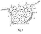
Figure 1 is a schematic side elevation of a gully containing a fascine formed by a plurality of larger diameter inflatable hollow pipes and a plurality of smaller diameter tubes, -
Figure 2 is a schematic cross-section of part of a cross-thread fabric for forming the larger diameter inflatable hollow pipes, -
Figure 3 is detail at X ofFigure 2 , -
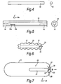
Figure 4 shows a larger diameter pipe of the kind shown inFigure 1 in side elevation and end elevation and deflated, -
Figure 5 shows the larger diameter pipe ofFigure 1 in cross section elevation and end elevation and inflated, -
Figure 6 shows a tube of the kind shown inFigure 1 in a deflated state and incorporating an inflation system, -
Figure 7 is a similar view toFigure 6 but showing the inflation system actuated and the tube inflated. - Referring first to
Figure 1 , the fascine comprises a plurality of larger diameter inflatedpipes 10 and a plurality of smaller diameter inflatedtubes 11. The larger diameter inflatedpipes 10 fill the lower portion of agully 12 while the smaller diameter inflatedtubes 11 overlie the larger diameter inflatedpipes 10 to form a passage across thegully 12. - Referring next to
Figures 2 and 3 , eachpipe 10 is elongate and is formed from a sheet of drop-thread fabric of the kind shown inFigures 3 and4 . As seen in this Figure, the fabric comprises afirst textile layer 13 interconnected to asecond textile layer 14 by a plurality of drop-threads shown schematically at 15. Both thefirst layer 13 and thesecond layer 14 are provided with an inner coating of polychloroprene, atextile chaffing layer 16 then an outer coating of polychloroprene. An elongate rectangular sheet of such drop-thread material has the side edges of thefirst textile layer 13 connected together and the side edges of thesecond textile layer 14 connected together to form a hollow pipe with a first end and a second end. The edges at the first and second ends are also closed so that a closed chamber is formed within thefirst textile layer 13 and thesecond textile layer 14. Thefirst textile layer 13 thus forms an outer wall of thepipe 10 and the second textile later 14 an inner wall of thepipe 10. Eachpipe 10 may be provided with an outer cover of wear-resistant material. - Each
pipe 10 carries aninflation system 18 formed by two inflation cylinders and associated valve systems. As seen inFigure 5 , the inflation systems are located within the associatedpipe 10 with one system being adjacent one end of thetube 10 and the other system adjacent an opposite end of thetube 10. Thevalve system 19a, when actuated, opens a valve and allows gas from theinflation cylinder 18 to inflate the chamber of thepipe 10. Aswitch 19b is provided for actuating the inflation systems. The switch may be manually operated or electrically operated. The electric operation may be remote via wire or be bywireless connection 19c. - Inflatable pipes of this kind are described in more detail in
GB-A-2 401 640 - Each smaller diameter
inflatable tube 11 is formed from a conventional coated fabric material. Eachtube 11 is provided with aninflation system 20 that, as seen inFigures 6 and 7 , is located within the associatedtube 11. Eachinflation system 20 comprises agas cylinder 21 and avalve system 22 carried by amounting plate 23. Themounting plate 23 allows theinflation system 20 to be removed and replaced easily. On operation of thevalve system 22, gas from thegas cylinder 21 leaves thevalve system 22 through anoutlet 27 to inflate thetube 11. Theinflation system 20 may be actuated by aswitch 28 located within thetube 11. Theswitch 28 may be manually operated or electrically operated. The electric operation may be remote via wire or by awireless connection 29. - The
inflation system 20 could incorporate an aspiration system (shown in broken line at 30) by which ambient air is drawn into thetube 11 as gas from thecylinder 21 inflates the tube. This increases the speed of inflation. Such aspiration systems are known and will not be described in detail. - The advantage of locating the
gas cylinder 21 within the associatedtube 11 is to provide protection for thegas cylinder 21 and the other parts of the inflation system in the post-inflation phase. There is a significantly reduced chance of the inflation system being damaged after thetube 11 has been inflated. The system will give faster inflation with fewer problems of icing if the gas is vented directly from the cylinder without needing to pass down pipes. There are fewer components and valve parts which give increased reliability and improve performance. It gives the fascine a reduced radar image and possibly a reduced thermal image because it is screened by thetube 11. If anaspiration system 30 is provided it allows a smaller gas cylinder to be used. This reduces bulk and cost. - The exterior diameter of the
pipes 10, when inflated, may be between 0.5m and 1.0m. The exterior diameter of thetubes 11, when inflated, may be between 0.2m and 0.5m. - The
tubes 11 may be covered with a wear-resistant cover. In addition, thetubes 11 may be double skinned to provide resistance to puncturing. - In use, the
pipes 10 are deflated and vacuum packed separately from one another as seen inFigure 4 . Likewise, thetubes 11 are deflated and vacuum packed separately from one another. In this way, the fascine components can be readily transported as they are lightweight and compact. When a discontinuity is reached that needs to be filled by the fascine, an estimate is made of the number ofpipes 10 required to fill the discontinuity. In the example shown inFigure 1 , fivesuch pipes 10 are required. The required number of pipes are placed in the discontinuity and the walls inflated using thecylinders 18 and valve systems 19. Inflation can be either be via an initiation cable or electronically, perhaps by remote signal. On inflation, the valve systems 19 open and gas from theinflation cylinders 18 passes into thepipes 10 to inflate the walls of thepipes 10. - Once the
pipes 10 are inflated, an estimate is also made of the number oftubes 11 required to cover thepipes 10 and form a trackway across the discontinuity. In the example shown inFigure 1 , eightsuch tubes 11 are required. Thetubes 11 are placed in the discontinuity and are then inflated by operation of thevalve systems 22 to open the gas cylinders and inflate thetubes 11. Theinflated tubes 11 then form the trackway over theinflated pipes 10. - It would be possible to inflate the
trackway tubes 11 away from the discontinuity and then locate them over thepipes 10 to form the trackway. - The trackway may be covered by additional members (not shown) such as a heavy duty layer of material such as Kevlar as well as a chaffing layer.
- It will be appreciated that the feature of locating the inflation system within the inflation chamber of the
tubes 11 may also be applied to thepipes 10. The feature need not be used with both thelarger diameter pipes 10 andsmaller diameter tubes 11. It could be used with either one or the other.
Claims (13)
- A fascine comprising an assembly of elongate members (10, 11), at least one member (10, 11) including an inflatable chamber and an inflation system (18, 20) for inflating said chamber characterised in that said inflation system (18, 20) is located within said chamber.
- A fascine according to claim 1 wherein said chamber when inflated, defines a cylindrical tube (11).
- A fascine according to claims 1 or claim 2 and including switch means (19b, 28) activatable to operate said inflation system (18, 20),
- A fascine according to claim 3 wherein said switch means (19b, 28) is manually actuated.
- A fascine according to claim 3 wherein the switch means (19b, 28) is electrically actuated.
- A fascine according to claim 5 wherein said switch means (19b, 28) is remotely actuated.
- A fascine according to claim 6 wherein said remote actuation is via a wire.
- A fascine according to claim 6 wherein said remote actuation is wireless (19c, 29).
- A fascine according to any one of claims 3 to 9 wherein said inflation system (18, 20) includes a rupturable component, activation of said switch means (19b, 28) rupturing said component to inflate said at least one member.
- A fascine according to any preceding claim wherein said at least one member (10, 11) includes a second inflation means (30).
- A fascine according to claim 10 wherein said second inflation means (30) includes aspiration means operative to draw into said at least one member (10, 11) air from outside said at least one member (10, 11).
- A fascine according to any preceding claim wherein said at least one member (10, 11) has an outside cover of wear resistant material.
- A fascine according to any preceding claim wherein said least one member (10, 11) is one of a plurality of such members.
Applications Claiming Priority (2)
| Application Number | Priority Date | Filing Date | Title |
|---|---|---|---|
| GBGB0420174.5A GB0420174D0 (en) | 2004-09-10 | 2004-09-10 | Fascines |
| PCT/GB2005/003391 WO2006027555A2 (en) | 2004-09-10 | 2005-09-02 | Fascines |
Publications (2)
| Publication Number | Publication Date |
|---|---|
| EP1786978A2 EP1786978A2 (en) | 2007-05-23 |
| EP1786978B1 true EP1786978B1 (en) | 2009-03-18 |
Family
ID=33186846
Family Applications (1)
| Application Number | Title | Priority Date | Filing Date |
|---|---|---|---|
| EP05776092A Expired - Lifetime EP1786978B1 (en) | 2004-09-10 | 2005-09-02 | Fascines |
Country Status (6)
| Country | Link |
|---|---|
| US (1) | US20080196182A1 (en) |
| EP (1) | EP1786978B1 (en) |
| AT (1) | ATE426063T1 (en) |
| DE (1) | DE602005013396D1 (en) |
| GB (1) | GB0420174D0 (en) |
| WO (1) | WO2006027555A2 (en) |
Families Citing this family (2)
| Publication number | Priority date | Publication date | Assignee | Title |
|---|---|---|---|---|
| GB2447030B (en) * | 2007-02-27 | 2011-08-24 | Survitec Group Ltd | Fascines |
| US9617696B1 (en) * | 2014-04-21 | 2017-04-11 | The United States Of America As Represented By The Secretary Of The Army | Lightweight universal gap crossing device and method of use |
Family Cites Families (24)
| Publication number | Priority date | Publication date | Assignee | Title |
|---|---|---|---|---|
| US2964050A (en) * | 1959-05-14 | 1960-12-13 | Joseph F Novak | Automatically actuated fluid pressure discharge valve |
| NL6816093A (en) * | 1968-11-12 | 1970-05-14 | ||
| US3685066A (en) * | 1971-03-10 | 1972-08-22 | David V Edwards | Liferaft inflation system |
| FR2229814A1 (en) * | 1973-05-16 | 1974-12-13 | Superflexit | |
| US4185373A (en) * | 1977-10-25 | 1980-01-29 | General Dynamics Corporation | Method of manufacturing an inflatable air inlet duct |
| US4312601A (en) * | 1979-02-26 | 1982-01-26 | The Secretary Of State For Defence In Her Britannic Majesty's Government Of The United Kingdom Of Great Britain And Northern Ireland | Fascines |
| GB8332525D0 (en) * | 1983-12-06 | 1984-01-11 | Secr Defence | Conformable fascine |
| US4646787A (en) * | 1985-03-18 | 1987-03-03 | Institute Of Gas Technology | Pneumatic pipe inspection device |
| US4639960A (en) * | 1985-04-16 | 1987-02-03 | Quillen Jeffrey B | Recliner for medical convalescence |
| US4862533A (en) * | 1987-09-18 | 1989-09-05 | Adams Iii Mark H | Sleeping bag and an air mattress |
| GB8727166D0 (en) * | 1987-11-20 | 1987-12-23 | Stewart K | Creating inflatable products |
| GB8824871D0 (en) * | 1988-10-24 | 1988-11-30 | Secr Defence | Fascine |
| US4966491A (en) * | 1989-08-01 | 1990-10-30 | Sample Jay W | Subsurface dune protection system and method |
| GB9119908D0 (en) * | 1991-09-18 | 1991-10-30 | Secr Defence | Apparatus for launching inflatable fascines |
| US5421128A (en) * | 1994-01-14 | 1995-06-06 | Sharpless; Garrett C. | Curved, inflated, tubular beam |
| GB9502903D0 (en) * | 1995-02-15 | 1995-04-05 | Gordon Peter C | Inflation device |
| US5720495A (en) * | 1996-01-16 | 1998-02-24 | Trw Vehicle Safety Systems Inc. | Air bag inflator with clamping ring for rupturable disk |
| US5967694A (en) * | 1998-01-28 | 1999-10-19 | Intevep, S.A. | Portable roadway and method of assembling same |
| US6887173B2 (en) * | 1999-10-14 | 2005-05-03 | Russell Asset Management, Inc. | Inflatable articles with self-contained inflation mechanism |
| EP1284624B1 (en) * | 2000-05-17 | 2008-03-26 | CHAFFEE, Robert B. | Inflatable device with recessed fluid controller and modified adjustment device |
| AU2002305862A1 (en) * | 2001-06-07 | 2002-12-16 | Select Comfort Corporation | Interactive air bed |
| ES2235010T3 (en) * | 2001-07-20 | 2005-07-01 | Prospective Concepts Ag | PNEUMATIC CONSTRUCTION OR BRIDGE ELEMENT. |
| SE0300565L (en) * | 2003-03-04 | 2004-01-13 | Karl Rainer Massarsch | Anti-vibration screen |
| GB2401640B (en) * | 2003-05-12 | 2006-05-03 | Beaufort Air Sea Equipment Ltd | Fascines |
-
2004
- 2004-09-10 GB GBGB0420174.5A patent/GB0420174D0/en not_active Ceased
-
2005
- 2005-09-02 AT AT05776092T patent/ATE426063T1/en not_active IP Right Cessation
- 2005-09-02 WO PCT/GB2005/003391 patent/WO2006027555A2/en not_active Ceased
- 2005-09-02 EP EP05776092A patent/EP1786978B1/en not_active Expired - Lifetime
- 2005-09-02 US US11/574,617 patent/US20080196182A1/en not_active Abandoned
- 2005-09-02 DE DE602005013396T patent/DE602005013396D1/en not_active Expired - Lifetime
Also Published As
| Publication number | Publication date |
|---|---|
| WO2006027555A3 (en) | 2006-05-04 |
| GB0420174D0 (en) | 2004-10-13 |
| US20080196182A1 (en) | 2008-08-21 |
| EP1786978A2 (en) | 2007-05-23 |
| DE602005013396D1 (en) | 2009-04-30 |
| WO2006027555A2 (en) | 2006-03-16 |
| ATE426063T1 (en) | 2009-04-15 |
Similar Documents
| Publication | Publication Date | Title |
|---|---|---|
| US7819063B1 (en) | Inflatable explosive breaching device | |
| US20050016372A1 (en) | Vessel immobiliser projectile | |
| EP0450975A2 (en) | Lining conduits, and device therefor | |
| WO1999030966A1 (en) | Immobiliser device | |
| WO2006127816A1 (en) | Apparatus and method for closing a fluid path | |
| US9022750B2 (en) | Alternative methods to generate high pressure by iteration in a high-pressure multichamber | |
| WO2009009894A1 (en) | Deformable/inflatable wear liner | |
| CN111119998B (en) | Quick water gushing prevention device for underwater tunnel | |
| US6644596B1 (en) | Deployment system for inflatable structures | |
| US7156033B2 (en) | Inflating aircraft flotation device | |
| US6470784B1 (en) | Defense system for an anti-intrusion area | |
| US20080196182A1 (en) | Fascines | |
| KR0171044B1 (en) | Inflatable pipe bundle | |
| CN109183718A (en) | Folding expansion type inflatable anti-collision connecting bridge | |
| US7435034B2 (en) | Fascines | |
| EP0655040B1 (en) | Device and method for the emergency emptying of the tanks of oil tankers in distress | |
| CN101370709B (en) | Ship hull protection device and method for protecting ship hull through inflatable device | |
| EP3420141B1 (en) | Inflatable booms | |
| KR20120056315A (en) | Floating apparatus, floating system having the same and recovering method of underwater moving object | |
| WO2005019026A3 (en) | Safety device trigger | |
| JP4106182B2 (en) | A device for laying temporary surface covering material stored in a rolled state on the ground surface | |
| EP0819447B1 (en) | Fire protection system | |
| CN114323556A (en) | Watertight partition device applied to underwater launching simulation system of navigation device | |
| US20060048665A1 (en) | Inflatable member projectile | |
| KR20040027306A (en) | A verify device sunken ship location |
Legal Events
| Date | Code | Title | Description |
|---|---|---|---|
| PUAI | Public reference made under article 153(3) epc to a published international application that has entered the european phase |
Free format text: ORIGINAL CODE: 0009012 |
|
| 17P | Request for examination filed |
Effective date: 20070216 |
|
| AK | Designated contracting states |
Kind code of ref document: A2 Designated state(s): AT BE BG CH CY CZ DE DK EE ES FI FR GB GR HU IE IS IT LI LT LU LV MC NL PL PT RO SE SI SK TR |
|
| DAX | Request for extension of the european patent (deleted) | ||
| 17Q | First examination report despatched |
Effective date: 20080404 |
|
| GRAP | Despatch of communication of intention to grant a patent |
Free format text: ORIGINAL CODE: EPIDOSNIGR1 |
|
| GRAS | Grant fee paid |
Free format text: ORIGINAL CODE: EPIDOSNIGR3 |
|
| GRAA | (expected) grant |
Free format text: ORIGINAL CODE: 0009210 |
|
| AK | Designated contracting states |
Kind code of ref document: B1 Designated state(s): AT BE BG CH CY CZ DE DK EE ES FI FR GB GR HU IE IS IT LI LT LU LV MC NL PL PT RO SE SI SK TR |
|
| REG | Reference to a national code |
Ref country code: GB Ref legal event code: FG4D |
|
| REG | Reference to a national code |
Ref country code: CH Ref legal event code: EP |
|
| REG | Reference to a national code |
Ref country code: IE Ref legal event code: FG4D |
|
| REF | Corresponds to: |
Ref document number: 602005013396 Country of ref document: DE Date of ref document: 20090430 Kind code of ref document: P |
|
| PG25 | Lapsed in a contracting state [announced via postgrant information from national office to epo] |
Ref country code: LT Free format text: LAPSE BECAUSE OF FAILURE TO SUBMIT A TRANSLATION OF THE DESCRIPTION OR TO PAY THE FEE WITHIN THE PRESCRIBED TIME-LIMIT Effective date: 20090318 Ref country code: SI Free format text: LAPSE BECAUSE OF FAILURE TO SUBMIT A TRANSLATION OF THE DESCRIPTION OR TO PAY THE FEE WITHIN THE PRESCRIBED TIME-LIMIT Effective date: 20090318 Ref country code: NL Free format text: LAPSE BECAUSE OF FAILURE TO SUBMIT A TRANSLATION OF THE DESCRIPTION OR TO PAY THE FEE WITHIN THE PRESCRIBED TIME-LIMIT Effective date: 20090318 Ref country code: FI Free format text: LAPSE BECAUSE OF FAILURE TO SUBMIT A TRANSLATION OF THE DESCRIPTION OR TO PAY THE FEE WITHIN THE PRESCRIBED TIME-LIMIT Effective date: 20090318 |
|
| PG25 | Lapsed in a contracting state [announced via postgrant information from national office to epo] |
Ref country code: LV Free format text: LAPSE BECAUSE OF FAILURE TO SUBMIT A TRANSLATION OF THE DESCRIPTION OR TO PAY THE FEE WITHIN THE PRESCRIBED TIME-LIMIT Effective date: 20090318 Ref country code: AT Free format text: LAPSE BECAUSE OF FAILURE TO SUBMIT A TRANSLATION OF THE DESCRIPTION OR TO PAY THE FEE WITHIN THE PRESCRIBED TIME-LIMIT Effective date: 20090318 Ref country code: PL Free format text: LAPSE BECAUSE OF FAILURE TO SUBMIT A TRANSLATION OF THE DESCRIPTION OR TO PAY THE FEE WITHIN THE PRESCRIBED TIME-LIMIT Effective date: 20090318 Ref country code: SE Free format text: LAPSE BECAUSE OF FAILURE TO SUBMIT A TRANSLATION OF THE DESCRIPTION OR TO PAY THE FEE WITHIN THE PRESCRIBED TIME-LIMIT Effective date: 20090618 |
|
| NLV1 | Nl: lapsed or annulled due to failure to fulfill the requirements of art. 29p and 29m of the patents act | ||
| PG25 | Lapsed in a contracting state [announced via postgrant information from national office to epo] |
Ref country code: BE Free format text: LAPSE BECAUSE OF FAILURE TO SUBMIT A TRANSLATION OF THE DESCRIPTION OR TO PAY THE FEE WITHIN THE PRESCRIBED TIME-LIMIT Effective date: 20090318 |
|
| PG25 | Lapsed in a contracting state [announced via postgrant information from national office to epo] |
Ref country code: EE Free format text: LAPSE BECAUSE OF FAILURE TO SUBMIT A TRANSLATION OF THE DESCRIPTION OR TO PAY THE FEE WITHIN THE PRESCRIBED TIME-LIMIT Effective date: 20090318 Ref country code: CZ Free format text: LAPSE BECAUSE OF FAILURE TO SUBMIT A TRANSLATION OF THE DESCRIPTION OR TO PAY THE FEE WITHIN THE PRESCRIBED TIME-LIMIT Effective date: 20090318 Ref country code: PT Free format text: LAPSE BECAUSE OF FAILURE TO SUBMIT A TRANSLATION OF THE DESCRIPTION OR TO PAY THE FEE WITHIN THE PRESCRIBED TIME-LIMIT Effective date: 20090827 Ref country code: ES Free format text: LAPSE BECAUSE OF FAILURE TO SUBMIT A TRANSLATION OF THE DESCRIPTION OR TO PAY THE FEE WITHIN THE PRESCRIBED TIME-LIMIT Effective date: 20090629 |
|
| PGFP | Annual fee paid to national office [announced via postgrant information from national office to epo] |
Ref country code: MC Payment date: 20090827 Year of fee payment: 5 |
|
| PG25 | Lapsed in a contracting state [announced via postgrant information from national office to epo] |
Ref country code: IS Free format text: LAPSE BECAUSE OF FAILURE TO SUBMIT A TRANSLATION OF THE DESCRIPTION OR TO PAY THE FEE WITHIN THE PRESCRIBED TIME-LIMIT Effective date: 20090718 Ref country code: SK Free format text: LAPSE BECAUSE OF FAILURE TO SUBMIT A TRANSLATION OF THE DESCRIPTION OR TO PAY THE FEE WITHIN THE PRESCRIBED TIME-LIMIT Effective date: 20090318 Ref country code: RO Free format text: LAPSE BECAUSE OF FAILURE TO SUBMIT A TRANSLATION OF THE DESCRIPTION OR TO PAY THE FEE WITHIN THE PRESCRIBED TIME-LIMIT Effective date: 20090318 |
|
| PGFP | Annual fee paid to national office [announced via postgrant information from national office to epo] |
Ref country code: LU Payment date: 20090929 Year of fee payment: 5 |
|
| PLBE | No opposition filed within time limit |
Free format text: ORIGINAL CODE: 0009261 |
|
| STAA | Information on the status of an ep patent application or granted ep patent |
Free format text: STATUS: NO OPPOSITION FILED WITHIN TIME LIMIT |
|
| PG25 | Lapsed in a contracting state [announced via postgrant information from national office to epo] |
Ref country code: BG Free format text: LAPSE BECAUSE OF FAILURE TO SUBMIT A TRANSLATION OF THE DESCRIPTION OR TO PAY THE FEE WITHIN THE PRESCRIBED TIME-LIMIT Effective date: 20090618 Ref country code: DK Free format text: LAPSE BECAUSE OF FAILURE TO SUBMIT A TRANSLATION OF THE DESCRIPTION OR TO PAY THE FEE WITHIN THE PRESCRIBED TIME-LIMIT Effective date: 20090318 |
|
| PGFP | Annual fee paid to national office [announced via postgrant information from national office to epo] |
Ref country code: CH Payment date: 20091006 Year of fee payment: 5 |
|
| 26N | No opposition filed |
Effective date: 20091221 |
|
| REG | Reference to a national code |
Ref country code: IE Ref legal event code: MM4A |
|
| PG25 | Lapsed in a contracting state [announced via postgrant information from national office to epo] |
Ref country code: IE Free format text: LAPSE BECAUSE OF NON-PAYMENT OF DUE FEES Effective date: 20090902 |
|
| PG25 | Lapsed in a contracting state [announced via postgrant information from national office to epo] |
Ref country code: GR Free format text: LAPSE BECAUSE OF FAILURE TO SUBMIT A TRANSLATION OF THE DESCRIPTION OR TO PAY THE FEE WITHIN THE PRESCRIBED TIME-LIMIT Effective date: 20090619 |
|
| PG25 | Lapsed in a contracting state [announced via postgrant information from national office to epo] |
Ref country code: IT Free format text: LAPSE BECAUSE OF FAILURE TO SUBMIT A TRANSLATION OF THE DESCRIPTION OR TO PAY THE FEE WITHIN THE PRESCRIBED TIME-LIMIT Effective date: 20090318 |
|
| PG25 | Lapsed in a contracting state [announced via postgrant information from national office to epo] |
Ref country code: MC Free format text: LAPSE BECAUSE OF NON-PAYMENT OF DUE FEES Effective date: 20100930 |
|
| REG | Reference to a national code |
Ref country code: CH Ref legal event code: PL |
|
| PG25 | Lapsed in a contracting state [announced via postgrant information from national office to epo] |
Ref country code: HU Free format text: LAPSE BECAUSE OF FAILURE TO SUBMIT A TRANSLATION OF THE DESCRIPTION OR TO PAY THE FEE WITHIN THE PRESCRIBED TIME-LIMIT Effective date: 20090919 |
|
| PG25 | Lapsed in a contracting state [announced via postgrant information from national office to epo] |
Ref country code: LI Free format text: LAPSE BECAUSE OF NON-PAYMENT OF DUE FEES Effective date: 20100930 Ref country code: CH Free format text: LAPSE BECAUSE OF NON-PAYMENT OF DUE FEES Effective date: 20100930 |
|
| PG25 | Lapsed in a contracting state [announced via postgrant information from national office to epo] |
Ref country code: TR Free format text: LAPSE BECAUSE OF FAILURE TO SUBMIT A TRANSLATION OF THE DESCRIPTION OR TO PAY THE FEE WITHIN THE PRESCRIBED TIME-LIMIT Effective date: 20090318 |
|
| PG25 | Lapsed in a contracting state [announced via postgrant information from national office to epo] |
Ref country code: CY Free format text: LAPSE BECAUSE OF FAILURE TO SUBMIT A TRANSLATION OF THE DESCRIPTION OR TO PAY THE FEE WITHIN THE PRESCRIBED TIME-LIMIT Effective date: 20090318 |
|
| PG25 | Lapsed in a contracting state [announced via postgrant information from national office to epo] |
Ref country code: LU Free format text: LAPSE BECAUSE OF NON-PAYMENT OF DUE FEES Effective date: 20100902 |
|
| PGFP | Annual fee paid to national office [announced via postgrant information from national office to epo] |
Ref country code: DE Payment date: 20130927 Year of fee payment: 9 |
|
| PGFP | Annual fee paid to national office [announced via postgrant information from national office to epo] |
Ref country code: GB Payment date: 20130927 Year of fee payment: 9 Ref country code: FR Payment date: 20130919 Year of fee payment: 9 |
|
| REG | Reference to a national code |
Ref country code: DE Ref legal event code: R119 Ref document number: 602005013396 Country of ref document: DE |
|
| GBPC | Gb: european patent ceased through non-payment of renewal fee |
Effective date: 20140902 |
|
| REG | Reference to a national code |
Ref country code: DE Ref legal event code: R119 Ref document number: 602005013396 Country of ref document: DE Effective date: 20150401 |
|
| REG | Reference to a national code |
Ref country code: FR Ref legal event code: ST Effective date: 20150529 |
|
| PG25 | Lapsed in a contracting state [announced via postgrant information from national office to epo] |
Ref country code: DE Free format text: LAPSE BECAUSE OF NON-PAYMENT OF DUE FEES Effective date: 20150401 Ref country code: GB Free format text: LAPSE BECAUSE OF NON-PAYMENT OF DUE FEES Effective date: 20140902 |
|
| PG25 | Lapsed in a contracting state [announced via postgrant information from national office to epo] |
Ref country code: FR Free format text: LAPSE BECAUSE OF NON-PAYMENT OF DUE FEES Effective date: 20140930 |