EP1785831A2 - Method of inheriting information identifying virtual volume and storage system using the same - Google Patents
Method of inheriting information identifying virtual volume and storage system using the same Download PDFInfo
- Publication number
- EP1785831A2 EP1785831A2 EP06251964A EP06251964A EP1785831A2 EP 1785831 A2 EP1785831 A2 EP 1785831A2 EP 06251964 A EP06251964 A EP 06251964A EP 06251964 A EP06251964 A EP 06251964A EP 1785831 A2 EP1785831 A2 EP 1785831A2
- Authority
- EP
- European Patent Office
- Prior art keywords
- logical volume
- virtualization apparatus
- volume
- virtualization
- vol
- Prior art date
- Legal status (The legal status is an assumption and is not a legal conclusion. Google has not performed a legal analysis and makes no representation as to the accuracy of the status listed.)
- Withdrawn
Links
Images









Classifications
-
- G—PHYSICS
- G06—COMPUTING OR CALCULATING; COUNTING
- G06F—ELECTRIC DIGITAL DATA PROCESSING
- G06F3/00—Input arrangements for transferring data to be processed into a form capable of being handled by the computer; Output arrangements for transferring data from processing unit to output unit, e.g. interface arrangements
- G06F3/06—Digital input from, or digital output to, record carriers, e.g. RAID, emulated record carriers or networked record carriers
- G06F3/0601—Interfaces specially adapted for storage systems
- G06F3/0628—Interfaces specially adapted for storage systems making use of a particular technique
- G06F3/0662—Virtualisation aspects
- G06F3/0665—Virtualisation aspects at area level, e.g. provisioning of virtual or logical volumes
-
- G—PHYSICS
- G06—COMPUTING OR CALCULATING; COUNTING
- G06F—ELECTRIC DIGITAL DATA PROCESSING
- G06F3/00—Input arrangements for transferring data to be processed into a form capable of being handled by the computer; Output arrangements for transferring data from processing unit to output unit, e.g. interface arrangements
- G06F3/06—Digital input from, or digital output to, record carriers, e.g. RAID, emulated record carriers or networked record carriers
- G06F3/0601—Interfaces specially adapted for storage systems
- G06F3/0602—Interfaces specially adapted for storage systems specifically adapted to achieve a particular effect
- G06F3/0604—Improving or facilitating administration, e.g. storage management
- G06F3/0607—Improving or facilitating administration, e.g. storage management by facilitating the process of upgrading existing storage systems, e.g. for improving compatibility between host and storage device
-
- G—PHYSICS
- G06—COMPUTING OR CALCULATING; COUNTING
- G06F—ELECTRIC DIGITAL DATA PROCESSING
- G06F3/00—Input arrangements for transferring data to be processed into a form capable of being handled by the computer; Output arrangements for transferring data from processing unit to output unit, e.g. interface arrangements
- G06F3/06—Digital input from, or digital output to, record carriers, e.g. RAID, emulated record carriers or networked record carriers
- G06F3/0601—Interfaces specially adapted for storage systems
- G06F3/0602—Interfaces specially adapted for storage systems specifically adapted to achieve a particular effect
- G06F3/0614—Improving the reliability of storage systems
- G06F3/0617—Improving the reliability of storage systems in relation to availability
-
- G—PHYSICS
- G06—COMPUTING OR CALCULATING; COUNTING
- G06F—ELECTRIC DIGITAL DATA PROCESSING
- G06F3/00—Input arrangements for transferring data to be processed into a form capable of being handled by the computer; Output arrangements for transferring data from processing unit to output unit, e.g. interface arrangements
- G06F3/06—Digital input from, or digital output to, record carriers, e.g. RAID, emulated record carriers or networked record carriers
- G06F3/0601—Interfaces specially adapted for storage systems
- G06F3/0628—Interfaces specially adapted for storage systems making use of a particular technique
- G06F3/0629—Configuration or reconfiguration of storage systems
- G06F3/0631—Configuration or reconfiguration of storage systems by allocating resources to storage systems
-
- G—PHYSICS
- G06—COMPUTING OR CALCULATING; COUNTING
- G06F—ELECTRIC DIGITAL DATA PROCESSING
- G06F3/00—Input arrangements for transferring data to be processed into a form capable of being handled by the computer; Output arrangements for transferring data from processing unit to output unit, e.g. interface arrangements
- G06F3/06—Digital input from, or digital output to, record carriers, e.g. RAID, emulated record carriers or networked record carriers
- G06F3/0601—Interfaces specially adapted for storage systems
- G06F3/0628—Interfaces specially adapted for storage systems making use of a particular technique
- G06F3/0646—Horizontal data movement in storage systems, i.e. moving data in between storage devices or systems
- G06F3/0647—Migration mechanisms
-
- G—PHYSICS
- G06—COMPUTING OR CALCULATING; COUNTING
- G06F—ELECTRIC DIGITAL DATA PROCESSING
- G06F3/00—Input arrangements for transferring data to be processed into a form capable of being handled by the computer; Output arrangements for transferring data from processing unit to output unit, e.g. interface arrangements
- G06F3/06—Digital input from, or digital output to, record carriers, e.g. RAID, emulated record carriers or networked record carriers
- G06F3/0601—Interfaces specially adapted for storage systems
- G06F3/0628—Interfaces specially adapted for storage systems making use of a particular technique
- G06F3/0662—Virtualisation aspects
- G06F3/0664—Virtualisation aspects at device level, e.g. emulation of a storage device or system
-
- G—PHYSICS
- G06—COMPUTING OR CALCULATING; COUNTING
- G06F—ELECTRIC DIGITAL DATA PROCESSING
- G06F3/00—Input arrangements for transferring data to be processed into a form capable of being handled by the computer; Output arrangements for transferring data from processing unit to output unit, e.g. interface arrangements
- G06F3/06—Digital input from, or digital output to, record carriers, e.g. RAID, emulated record carriers or networked record carriers
- G06F3/0601—Interfaces specially adapted for storage systems
- G06F3/0668—Interfaces specially adapted for storage systems adopting a particular infrastructure
- G06F3/067—Distributed or networked storage systems, e.g. storage area networks [SAN], network attached storage [NAS]
Definitions
- the technology disclosed in this specification is relates to a computer system including one or more storage systems, and more specifically, but not exclusively, relates to a volume migration in a virtualization environment in which the storage area is virtualized.
- the computer system includes a virtualization apparatus (virtualization switch 11) that provides a virtual volume.
- the virtualization apparatus associates one or more real areas on the storage system with a virtual volume (virtual volume 100).
- the host computer issues an input/output request to the virtual volume.
- the virtualization apparatus converts the input/output request into the input/output request relative to a real area corresponding to the virtual volume and transfers the converted request.
- a virtual volume that one of the virtualization apparatuses is managing may migrate to another virtualization apparatus.
- the volume migration is carried out by releasing the correspondence between the migration source virtual volume and the real area corresponding thereto, and by associating the real area with the migration destination virtual volume. Accordingly, the migration destination virtual volume is associated with the real area having been associated with the migration source virtual volume.
- the host recognizes that these volumes are different from each other. Thus, a system administrator needs to change the host setting so that the host recognizes that these volumes are identical to each other.
- One aspect of the invention includes a control method for a computer system including a host computer, one or more storage system, and plural virtualization apparatuses, the host computer being coupled to the plural virtualization apparatuses via a network, and the plural virtualization apparatuses being coupled to the one or more storage systems via the network, in which a first virtualization apparatus includes a first memory and manages a first logical volume to which the host computer issues an access request, and a second virtualization apparatus includes a second memory and manages a second logical volume to which the host computer issues an access request.
- the control method associates a first real storage area on the storage system, which has been associated with the first logical volume, with the second logical volume, and stores, in the second memory, first identification information that uniquely identifies the first logical volume within the computer system.
- the host when the virtual volume migrates between the virtualization apparatuses and although the system administrator does not change the host setting, the host can access a file on the migration destination volume.
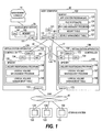
- Fig. 1 is a block diagram showing the configuration of a computer system of a first embodiment of this invention.
- the computer system of this embodiment includes a virtualization apparatus 13A, a virtualization apparatus 13B, a host computer 12, a management server 16, a management console 14, and one or more storage systems 133.
- a local area network (LAN) 15 is a communication path used for interconnecting the management server 16, the host computer 12, the virtualization apparatuses 13A and 13B to allow them to communicate with each other.
- a storage area network (SAN) 17 is a communication path used for interconnecting the host computer 12, the virtualization apparatuses 13A, 13B, and the individual storage systems 133 to allow them to send and receive the data.
- the communication is carried out, for example, based on the fibre channel (FC) protocol.
- the host computer 12, the virtualization apparatuses 13A and 13B connect with each other via the storage area network (SAN) 17. Further, the virtualization apparatuses 13A, 13B and the individual storage systems 133 connect with each other via the SAN 17.
- SAN storage area network
- the virtualization apparatus 13A is a device that provides a storage area within the storage system 133 as a virtualized logical volume 131 (see Fig. 2) to the host computer 12.
- the logical volume 131 will be described below with reference to Fig. 2.
- the virtualization apparatus 13A includes a controller 132 and a SAN interface (SAN_I/F) 172.
- SAN_I/F SAN interface
- the controller 132 includes a CPU 134, a memory 135, a network interface card (NIC) 151 and the SAN interface 172.
- NIC network interface card
- the CPU 134 is a processor that executes programs stored in the memory 135.
- the memory 135 of the embodiment stores at least an inquiry responding program 136, a logical volume management program 137 and a logical volume management table 138.
- the inquiry responding program 136 is a program that, when the virtualization apparatus 13A receives an inquiry request (INQUIRY command of SCSI, operation code 12h) from the host computer 12, creates inquiry information and sends the created inquiry information to the host computer 12.
- the inquiry information is more specifically the response information of a SCSI INQUIRY command.
- it is a vendor-specific table containing a portion of Standard INQUIRY data defined by the SCSI-1 standard, or Vital product data parameters defined by the SCSI-2 standard, and more preferably, Page code 80h (Unit Serial Number page) or Page code C0h-FFh.
- the inquiry request is a request that the host computer 12 sends to the virtualization apparatus 13A in order to acquire information (inquiry information) relating to the logical volume 131 of the virtualization apparatus 13A.
- the inquiry information includes the information relating to the logical volume 131. More specifically, the inquiry information includes the unit serial number of the virtualization apparatus 13A and the logical volume number of logical volume 131 as the identification information that uniquely identifies the logical volume 131 within the computer system.
- the host computer 12 refers to the inquiry information to identify the individual logical volumes 131. The inquiry information will be described in detail below (see Figs. 4A and 4B).
- the logical volume management program 137 is a program for executing such operations as the creation, deletion, renaming, migration of the logical volume 131 in response to an instruction from the management server 16 and the like.
- the logical volume management table 138 is a table for managing the logical volumes 131. Registered in the logical volume management table 138 is the information relating to the logical volumes 131 that the virtualization apparatus 13A provides to the host computer 12.
- the NIC 151 is an interface connecting with the LAN 15 to communicate with the management server 16 and other related modules.
- the SAN interface 172 is an interface connecting with the SAN 17 to communicate with the host computer 12, the virtualization apparatus 13B and the storage systems 133. More specifically, the SAN interface 172 is a host bus adapter (HBA) of the fibre channel (FC). Incidentally, it is allowable to use other protocols than the FC (e.g. SCSI, iSCSI or InfiniBand) for the connection between the host computer 12, the virtualization apparatus 13A and the storage systems 133. In this case, the SAN interface 172 may be the adapter corresponding to these protocols.
- HBA host bus adapter
- FC fibre channel
- the configuration of the virtualization apparatus 13B is the same as that of the virtualization apparatus 13A. Thereby, the description about the configuration of the virtualization apparatus 13B will be omitted.
- the virtualization apparatuses 13A and 13B are collectively referred to as a virtualization apparatus 13 when they do not specifically need to be differentiated from each other.
- the host computer 12 is a computer using the data of the logical volume 131 that the virtualization apparatus 13 provides (i.e. the data stored in the storage area of the storage system 133).
- the host computer 12 includes a CPU 121, a memory 122, the NIC 151 and the SAN interface 172.
- the CPU 121 is a processor for executing the programs stored in the memory 122.
- the memory 122 for example a semiconductor memory, stores various programs that the CPU 121 executes and tables to which these programs refer.
- the memory 122 of the embodiment stores at least an application program (AP) 123, a file system (FS) 124, a path management program 125, a mount table 126 and a device management table 127.
- AP application program
- FS file system
- the AP 123 is a program (e.g. a database management program) that executes jobs using the files on a virtual device (not shown).
- the virtual device is a virtual device that the FS 124 recognizes.
- the path management program 125 described below associates one virtual device with one logical volume 131.
- the FS 124 is a program that associates an area on the virtual device with a file read or written by the AP 123.
- the path management program 125 is a program that associates the virtual device with the logical volume 131.
- the mount table 126 is a table for managing the correspondence between the virtual device and the name of the file stored in the virtual device. More specifically, the virtual device name and the first character string of the filename given to the file on the virtual device are registered in the mount table 126.
- the FS 124 refers to the mount table 126.
- the device management table 127 is a table for managing the correspondence between the virtual device and the logical volume 131. More specifically, the unit serial number of the virtualization apparatus 13 and the logical volume name, as well as the virtual device name corresponding to them are registered in the device management table 127.
- the path management program 125 refers to and updates the device management table 127.
- the path management program 125, the mount table 126 and the device management table 127 will be described in detail below.
- the management server 16 is a computer for confirming and changing the setting of the virtualization apparatus 13.
- the management server 16 of the embodiment includes a CPU 161, a memory 162 and the NIC 151.
- the CPU 161 is a processor for executing the programs stored in the memory 162.
- the memory 162 for example a semiconductor memory, stores various programs that the CPU 161 executes.
- the memory 162 of the embodiment stores at least the programs (not shown) that issues the requests of the creation, deletion and migration of the logical volume 131 (see Fig. 7A) to the virtualization apparatus 13.
- the management console 14 is an input/output terminal that the system administrator uses for operating the management server.
- the storage system 133 connects with the virtualization apparatus 13 via the SAN 17.
- the individual storage system 133 can be handled at least as an independent device.
- the individual storage systems 133 may be a single disk drive, or a disk array apparatus including plural disk drives.
- the storage systems 133 each include one or more real volumes 139 (described below).
- the file data the AP 123 uses is stored in the real volume 139.
- Fig. 2 is an explanatory diagram showing the outline of the first embodiment of this invention.
- the apparatus identifiers identify the individual virtualization apparatuses 13.
- the apparatus identifier is, for example, the unit serial number of the virtualization apparatus 13.
- the unit serial number of the virtualization apparatus 13A is "U1”
- the unit serial number of the virtualization apparatus 13B is "U2”.
- the unit serial number may be an arbitrary character and numerical string.
- the unit serial number may include the information (model information) that identifies the model of each individual virtualization apparatus.
- the two logical volumes 131 are initially set to the virtualization apparatus 13A.
- the logical volume 131 is a virtual storage area corresponding to one or more real volumes 139 (described below).
- the virtualization apparatus 13 can provide one or more logical volumes 131 to the host computer 12.
- the individual logical volumes 131 can be identified by the logical volume numbers (identifiers).
- the volume numbers of the two logical volumes 131 of the virtualization apparatus 13A are "VOL-A" and "VOL-B".
- VOL-A the logical volume 131 with the volume number "VOL-A” is simply referred to as "VOL-A”. This is the same for the other logical volumes 131.
- the individual virtualization apparatuses 13 give unique volume numbers within the individual virtualization apparatuses 13 to the logical volumes 131, respectively.
- the combination of the unit serial number of the virtualization apparatus 13 and the volume number is used as the identification information that uniquely identifies each of the logical volumes 131 within the computer system.
- VOL-A and VOL-B correspond to one or more predetermined real volumes 139, respectively.
- the real volume 139 is a volume composed of the storage area on the storage system 133, in which the data is actually stored.
- the host computer 12 issues an access request to the logical volume 131.
- the requested access is actually executed relative to the real volume 139 corresponding to the logical volume 131.
- the host computer 12 issues a data writing request relative to VOL-A
- the data is actually stored in the real volume 139 corresponding to VOL-A.
- it looks from the host computer 12 as if the data were stored in VOL-A of the virtualization apparatus 13A.
- the fact that the data is stored in the real volume 139 corresponding to VOL-A will be simply referred to as "the data is stored in VOL-A". This is the same for VOL-B and VOL-C.
- the following description assumes that all of the logical volumes 131 correspond to the real volumes 139.
- the real volume 139 may be recognized as the logical volume 131 by itself.
- VOL-B migrates to VOL-C of the virtualization apparatus 13B. More specifically, the correspondence between VOL-B and the real volume 139 corresponding to VOL-B is released. Then, the real volume 139 is newly associated with VOL-C. As a result, the real volume 139 corresponding to VOL-C is the same real volume 139 having corresponded to VOL-B. Thus, although VOL-B migrates to VOL-C, the data does not move. However, it looks as if the data having been stored in VOL-B had moved to VOL-C from the host computer 12.
- Such a migration of the logical volume 131 is executed, for example, in order to disperse the access load of the virtualization apparatus 13.
- the host computer 12 issues a large amount of access requests to VOL-A and VOL-B, while a few access requests to the logical volume 131 of the virtualization apparatus 13B.
- the migration of VOL-B to the virtualization apparatus 13B allows a portion of the access load of the virtualization apparatus 13A to be dispersed to the virtualization apparatus 13B.
- the data process performance of the whole computer system is improved.
- VOL-B Upon completion of the migration from VOL-B to VOL-C, the access to VOL-B is prohibited. At this moment, the exactly same data as the data having been stored in VOL-B is stored in VOL-C.
- the file that the AP 123 uses has been stored in VOL-B, it needs to issue to VOL-C the access request for the AP 123 in order to access the file.
- the system administrator has needed to manually update the mount table 126 to which the FS 124 refers in order to change the destination of such an access request.
- the conventional virtualization apparatus 13B replied the inquiry information composed of the unit serial number "U2" of the virtualization apparatus 13B and the volume name "VOL-C" of VOL-C.
- VOL-B and VOL-C were corresponding to the same real volume 139
- the path management program 125 of the host computer 12 recognized VOL-C as the logical volume 131 different from VOL-B, and assigned a different virtual device name from VOL-B, to VOL-C.
- the system administrator needed to release the correspondence between the virtual device name of VOL-B (in the example of Fig. 2, "/dev/dsk/vo10002”) and the filename (in the example of Fig. 2, "/home2”), and to update the mount table 126 so as to newly establish the correspondence between the virtual device name of VOL-C (e.g. "dev/dsk/vo10003”) and the filename "/home2".
- the migration destination VOL-C inherits the unit serial number "U1" of the migration source virtualization apparatus 13A and the logical volume name "VOL-B" of the migration source logical volume 131 (see Figs 3A and 3B). Then, the virtualization apparatus 13B replies the inherited "U1" and "VOL-B" to the inquiry request from the host computer 12. Because of this feature, the path management program 125 recognizes that VOL-C is the same logical volume 131 as VOL-B, and assigns to VOL-C the same virtual device name as that of VOL-B. As a result, although the system administrator does not update the mount table 126, the AP 123 can use the file stored in VOL-C.
- the implementation of the embodiment requires that the inquiry information relating to the individual logical volumes 131 be unique within the computer system.
- the virtualization apparatus 13B inherits "U1" and "VOL-B" from the virtualization apparatus 13A, the virtualization apparatus 13A cannot give the volume name "VOL-B" to the newly created logical volume 131.
- Fig. 3A is an explanatory diagram of a logical volume management table 138 of the migration source virtualization apparatus 13A in the first embodiment of this invention.
- This logical volume management table 138 is a table for managing the logical volumes 131 stored in the virtualization apparatus 13A.
- the example of Fig. 3A shows the logical volume management table 138 after completion of the migration from VOL-B to VOL-C.
- the logical volume management table 138 includes a volume number 301 within virtualization apparatus, a unit serial number 302 of creation source virtualization apparatus and a volume number 303 at creation time.
- the unit serial number 302 of creation source virtualization apparatus and the volume number 303 at creation time have not been included in the conventional logical volume management table, so that they are added in the embodiment of this invention.
- the volume number 301 within virtualization apparatus is the logical volume number of the logical volume 131 stored in the virtualization apparatus 13A.
- the virtualization apparatus 13A initially stores the two logical volumes 131, VOL-A and VOL-B (see Fig. 2). At this moment, "VOL-A” and “VOL-B” are registered as the volume numbers 301 within virtualization apparatus. Subsequently, VOL-B migrates to VOL-C, and VOL-B is deleted from the virtualization apparatus 13A.
- VOL-B has been deleted from the volume number 301 within virtualization apparatus in association with the deletion of VOL-B.
- "VOL-B” is not deleted from the volume number 301 within virtualization apparatus. This is for preventing the virtualization apparatus 13A from giving the volume number "VOL-B” to the newly created logical volume 131. Because the migration destination VOL-C inherits and uses "U1" and "VOL-B", if the virtualization apparatus 13A gives the volume number "VOL-B" to the newly created logical volume 131, the inquiry information is not unique within the computer system.
- the unit serial number of the migration source virtualization apparatus 13 is registered for the unit serial number 302 of creation source virtualization apparatus. This unit serial number of the migration source virtualization apparatus 13 is registered by being associated with the volume number of the migrated logical volume 131.
- VOL-A and VOL-B of the virtualization apparatus 13A are both created by the virtualization apparatus 13A.
- the unit serial numbers 302 of creation source virtualization apparatus for VOL-A and VOL-B are initially both blank ("-"). Subsequently, VOL-B migrates to VOL-C, and VOL-B is deleted from the virtualization apparatus 13A. At this time, the unit serial number "U1" of the virtualization apparatus 13A is registered as the unit serial number 302 of creation source virtualization apparatus of VOL-B.
- the migration source logical volume number is stored for the volume number 303 at creation time.
- Fig. 3B is an explanatory diagram of a logical volume management table 138 of the migration destination virtualization apparatus 13B in the first embodiment of this invention.
- This volume management table 138 is a table for managing the logical volume 131 stored in the virtualization apparatus 13B.
- the example of Fig. 3B shows the logical volume management table 138 after completion of the migration from VOL-B to VOL-C.
- the description about the same parts as those in Fig. 3A will be omitted.
- the virtualization apparatus 13B stores VOL-C (see Fig. 2). Thus, "VOL-C" is registered as the volume number 301 within virtualization apparatus.
- VOL-C is a logical volume created as the migration destination of VOL-B of the virtualization apparatus 13B.
- the unit serial number "U1" of the migration source virtualization apparatus 13A is registered as the unit serial number 302 of creation source virtualization apparatus of VOL-C.
- the volume number "VOL-B" of the migration source logical volume 131 is registered as the volume number 303 at creation time of VOL-C.
- Fig. 4A is an explanatory diagram showing an example of the inquiry information of the first embodiment of this invention.
- Fig. 4A shows inquiry information 400 that the virtualization apparatus 13A replies, when the host computer 12 of Fig. 2 issues the inquiry request relative to VOL-A of the virtualization apparatus 13A.
- the inquiry responding program 136 creates the inquiry information 400.
- the procedure of the process the inquiry responding program 136 executes will be described in detail below (see Fig. 8).
- the inquiry information 400 of the embodiment includes a apparatus identifier (unit serial number) 401 and a volume number 402.
- the unit serial number 302 of creation source virtualization apparatus for VOL-A is blank (see Fig. 3A).
- the unit serial number "U1" of the virtualization apparatus 13A that manages VOL-A is registered for the apparatus identifier 401, and the volume number "VOL-A" that the virtualization apparatus 13A has given to VOL-A is registered for the volume number 402.
- Fig. 4B is an explanatory diagram showing another example of the inquiry information in the first embodiment of this invention.
- Fig. 4B shows the inquiry information 400 that the virtualization apparatus 13B replies when the host computer 12 of Fig. 2 issues the inquiry request relative to VOL-C of the virtualization apparatus 13B.
- the description about the same parts as those in Fig. 4A will be omitted.
- the virtualization apparatus 13B manages VOL-C.
- the conventional inquiry responding program 136 registers the unit serial number "U2" of the virtualization apparatus 13B that manages VOL-C and the volume number "VOL-C" that the virtualization apparatus 13B has given to VOL-C, as the apparatus identifier 401 and the volume number 402 respectively.
- the inquiry responding program 136 of the embodiment registers the unit serial number and volume number inherited from the migration source and replies to the host computer 12.
- the logical volume management table 138 of the virtualization apparatus 13B stores therein "U1" and "VOL-B” for the unit serial number 302 of creation source virtualization apparatus and the volume number 303 at creation time of VOL-C, respectively (see Fig. 3B).
- VOL-C is the logical volume 131 created as the migration destination of VOL-B of the virtualization apparatus 13B.
- "U1" and “VOL-B” are the values the virtualization apparatus 13B has inherited from the migration source virtualization apparatus 13A. In this case, "U1" and “VOL-B" are registered for the apparatus identifier 401 and the volume number 402 respectively.
- Fig. 5 is an explanatory diagram showing the device management table 127 of the first embodiment of this invention.
- Fig. 5 shows the device management table 127 of the host computer 12 shown in Fig. 2.
- the path management program 125 refers to and updates the device management table 127. The procedure of the process the path management program 125 executes will be described below in detail (see Fig. 9).
- the device management table 127 includes a apparatus identifier (unit serial number) 501, a volume number 502, a virtual device name 503 and an identifier 504 on SAN.
- Registered for the apparatus identifier 501 and the volume number 502 are the values of the inquiry information that the host computer 12 acquired by issuing the inquiry request, respectively.
- the host computer 12 acquires the unit serial number "U1" and the volume name "VOL-A” from the virtualization apparatus 13A (see Fig. 4A).
- "U1" as the apparatus identifier 501 and "VOL-A” as the volume number 502 are registered in a first entry (line) of the device management table 127.
- the host computer 12 acquires the unit serial number "U1" and the volume name "VOL-B” from the virtualization apparatus 13B (see Fig. 4B).
- "U1" as the apparatus identifier 501 and "VOL-B" as the volume number 502 are registered in a second entry of the device management table 127.
- the virtual device name 503 is a name used for the host computer 12 to recognize the logical volume 131 as the virtual device.
- "/dev/dsk/vo10001" is registered as the virtual device name 503 corresponding to VOL-A
- "/dev/dsk/vo10002" is registered as the virtual device name 503 corresponding to VOL-B.
- the identifier 504 on SAN is an identifier used for identifying the individual logical volumes 131 on the SAN 17.
- "0x90abcdef'' is registered as the identifier on SAN 504 corresponding to VOL-A
- "0x12345678" is registered as the identifier on SAN 504 corresponding to VOL-B.
- Fig. 6 is an explanatory diagram showing the mount table 126 of the first embodiment of this invention.
- Fig. 6 shows the mount table 126 of the host computer 12 shown in Fig. 2.
- the FS 124 refers to the mount table 126. The procedure of the process the FS 124 executes will be described below in detail (see Fig. 10).
- the mount table 126 includes a virtual device name 601 and a filename first character string 602.
- the host computer 12 recognizes the two virtual devices.
- the names of the two virtual devices "/dev/dsk/vol0001" and "/dev/dsk/vo10002" are registered for the virtual device name 601 of the mount table 126.
- the filename first character string 602 is the first character string of a filename given to a file on each virtual device.
- "/home1" is registered as the filename first character string 602 corresponding to the virtual device name "/dev/dsk/vo10001”
- "/home2" is registered as the filename first character string 602 corresponding to the virtual device name "/dev/dsk/vo10002”.
- the filename "/home2/testuser/filse1.txt” is given to the file on the virtual device with the virtual device name 601 of "/dev/dsk/vo10002”.
- the filenames beginning with "/home2" are given to the other files on the virtual device.
- the processes that the programs of the embodiment execute will be described with reference to the flowcharts.
- the processes that the individual programs execute are actually executed by the CPU 121 and other related modules that execute the programs. More specifically, the CPU 121 of the host computer 12 executes the processes of the FS 124 and the path management program 125.
- the CPU 134 of the virtualization apparatus 13 executes the processes of the inquiry responding program 136 and the logical volume management program 137.
- the host computer 12 and the virtualization apparatuses 13 send and receive therebetween the inquiry request and the inquiry information 400 via the SAN interface 172 and the SAN 17.
- the virtualization apparatuses 13 send and receive therebetween the identification information of the logical volume 131 via the SAN interface 172 and the SAN 17.
- the virtualization apparatuses 13 may also send and receive therebetween the identification information of the logical volume 131 via the NIC 151 and the LAN 15.
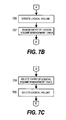
- Figs. 7A to 7E are flowcharts showing the processes of the logical volume management program 137 of the first embodiment of this invention.
- the logical volume management program 137 of the embodiment when receiving the volume creation request, volume deletion request or volume migration request from the management server 16, executes the processes in response to the requests. Further, the logical volume management program 137 of the embodiment, when receiving the volume migration request from another virtualization apparatus 13, executes the process in response to the request. These processes will be described below.
- the logical volume management program 137 Upon starting execution, the logical volume management program 137 waits for an event (Step 701 of Fig. 7A).
- the logical volume management program 137 determines whether or not the received request is the volume creation request that the management server 16 has issued (Step 702).
- Step 702 when it is determined that the received request is the volume creation request that the management server 16 has issued, the logical volume management program 137 creates the requested logical volume 131 (Step 706 of Fig. 7B). More specifically, the logical volume management program 137 secures the real volume 139 corresponding to the logical volume 131 that is the target of the creation request, on the storage system 133, and associates the real volume 139 with the logical volume 131.
- the area on the real volume 139 corresponding to the logical volume may be one or more of the entire real volumes 139, or may be a partial area of the real volume 139 or a group of the partial areas thereof.
- the logical volume management program 137 assigns an entry (a line) of the logical volume management table 138 to the created logical volume 131 (Step 707).
- the volume number newly given to the created logical volume 131 is registered for the volume number 301 within virtualization apparatus.
- the unit serial number 302 of creation source virtualization apparatus and volume number 303 at creation time corresponding to the created logical volume 131 are both blank.
- the logical volume management program 137 of the virtualization apparatus 13A when receiving the request to create VOL-A, secures the real volume 139 corresponding to VOL-A, and associates the real volume 139 with VOL-A (Step 706). Then, the logical volume management program 137 assigns an entry of the logical volume management table 138 to VOL-A (Step 707). At this time, the unit serial number 302 of creation source virtualization apparatus and volume number 303 at creation time corresponding to VOL-A are both blank (see Fig. 3A).
- the logical volume management program 137 executes Step 707, and then returns to Step 701.
- Step 702 when it is determined that the received request is not the volume creation request that the management server 16 has issued, the logical volume management program 137 determines whether or not the received request is the volume deletion request that the management server 16 has issued (Step 703).
- Step 703 when it is determined that the received request is the volume deletion request that the management server 16 has issued, the logical volume management program 137 deletes the entry corresponding to the logical volume 131 that is the target of the deletion request, from the logical volume management table 138 (Step 708 of Fig. 7C).
- the logical volume management program 137 executes the deletion of the requested logical volume 131 (Step 709). More specifically, the logical volume management program 137 releases the correspondence between the requested logical volume 131 and the real volume 139.
- the logical volume management program 137 executes Step 709, and then returns to Step 701.
- Step 703 when it is determined that the received request is not the volume deletion request the management server 16 has issued, the logical volume management program 137 determines whether or not the received request is the volume migration request that the management server 16 has issued (Step 704).
- the volume migration request that the management server 16 has issued is a request to migrate the logical volume 131 to the logical volume 131 of another virtualization apparatus 13.
- Step 704 when it is determined that the received request is the volume migration request that the management server 16 has issued, the logical volume management program 137 refers to the logical volume management table 138, and acquires the volume number 301 within virtualization apparatus corresponding to the logical volume 131 to be migrated (Step 710 of Fig. 7D).
- the logical volume management program 137 sends the configuration information of the logical volume 131, the unit serial number of the own virtualization apparatus, and the volume number 301 within virtualization apparatus acquired in Step 710, to the migration destination virtualization apparatus 13 (Step 711).
- the configuration information of the logical volume 131 includes information indicating the correspondence between the logical volume 131 to be migrated and the real volume 139 in which the data written in the logical volume 131 is actually stored.
- the unit serial number of the own virtualization apparatus is the unit serial number of the migration source virtualization apparatus 13 (i.e. the virtualization apparatus 13 to be the source of the information in Step 711).
- the logical volume management program 137 sends these pieces of information to the migration destination virtualization apparatus 13 as the volume migration request.
- Step 712 the logical volume management program 137 waits for the response from the migration destination virtualization apparatus 13 (Step 712).
- This response is sent in Step 718 of Fig. 7E described below.
- the transmission of this response indicates the completion of the migration of the logical volume 131.
- the logical volume management program 137 receives the response from the migration destination virtualization apparatus 13, and then registers the unit serial number of the own virtualization apparatus for the unit serial number 302 of creation source virtualization apparatus of the logical volume management table 138 corresponding to the migrated logical volume 131 (Step 713).
- the migrated logical volume 131 is the same as "the logical volume 131 to be migrated" in Step 710.
- Step 714 the logical volume management program 137 prohibits the access to the migrated logical volume.
- the logical volume management program 137 executes Step 714, and then returns to Step 701.
- the logical volume management program 137 refers to the logical volume management table 138 and acquires "VOL-B" in Step 710 (see Fig. 3A).
- Step 711 the logical volume management program 137 sends the configuration information of VOL-B, the unit serial number "U1" of the virtualization apparatus 13A, and "VOL-B" acquired in Step 710, to the virtualization apparatus 13B.
- the logical volume management program 137 receives the response from the virtualization apparatus 13B in Step 712, and then registers the unit serial number "U1" of the virtualization apparatus 13A for the unit serial number 302 of creation source virtualization apparatus corresponding to "VOL-B" of the logical volume management table 138 in Step 713 (see Fig. 3A).
- Step 714 the logical volume management program 137 prohibits the access to VOL-B (Step 714), and then returns to Step 701.
- Step 704 when it is determined that the received request is not the volume migration request that the management server 16 has issued, the logical volume management program 137 determines whether or not the received request is the volume migration request that another virtualization apparatus 13 has issued (Step 705).
- the volume migration request that another virtualization apparatus 13 has issued is a request to migrate the logical volume 131 of another virtualization apparatus 13 to the logical volume 131 of the own virtualization apparatus 13 (i.e. the virtualization apparatus 13 having received the request). This request is specifically the volume migration request having been sent in Step 711 of Fig. 7D.
- Step 705 when determining that the received request is the volume migration request that another virtualization apparatus 13 has issued, the logical volume management program 137 receives the configuration information of the logical volume 131, the unit serial number of the migration source virtualization apparatus 13, and the volume number 301 within virtualization apparatus (Step 715). These pieces of information are the ones sent in Step 711 of Fig. 7D.
- the logical volume management program 137 configures a new logical volume 131 (Step 716). More specifically, the logical volume management program 137 refers to the configuration information of the logical volume 131 received in Step 715, and associates the real volume 139 corresponding to the migration source logical volume 131 with the newly created logical volume 131.
- the logical volume management program 137 assigns one entry of the logical volume management table 138 to the newly configured logical volume 131 (Step 717).
- the volume number given to the newly configured logical volume is stored for the volume number 301 within virtualization apparatus of the entry.
- the unit serial number of the migration source virtualization apparatus 13 received in Step 715 is stored for the unit serial number 302 of creation source virtualization apparatus of the entry.
- the volume number 301 within virtualization apparatus received in Step 715 is stored for the volume number 303 at creation time of the entry.
- the logical volume management program 137 sends the volume migration response back to the migration source virtualization apparatus 13 (Step 718). This response is to notify about the completion of the migration of the logical volume 131.
- the logical volume management program 137 executes Step 718, and then returns to Step 701.
- the logical volume management program 137 of the virtualization apparatus 13B receives the configuration information of VOL-B, the unit serial number "U1" of the migration source virtualization apparatus 13A, and the volume number within virtualization apparatus "VOL-B" in Step 715.
- Step 716 the logical volume management program 137 configures VOL-C as a new logical volume.
- VOL-C is associated with the real volume 139 to which VOL-B has corresponded.
- Step 717 the logical volume management program 137 assigns one entry of the logical volume management table 138 to VOL-C.
- VOL-C for the virtualization apparatus volume number 301
- U1 for the serial number 302 of creation source virtualization apparatus
- VOL-B for the volume number 303 at creation time, respectively are stored in the entry. (see Fig. 3B).
- Step 718 the logical volume management program 137 sends the volume migration response back to the migration source virtualization apparatus 13A (Step 718), and then returns to Step 701.
- Fig. 8 is a flowchart showing the process of the inquiry responding program 136 of the first embodiment of this invention.
- the virtualization apparatus 13 receives the inquiry request relative to either of the logical volumes 131 from the host computer 12, and the process of the inquiry responding program 136 starts (Step 801).
- the inquiry responding program 136 refers to the logical volume management table 138 (Step 802). More specifically, the inquiry responding program 136 refers to the entry corresponding to the logical volume 131 that is the target of the inquiry request in the logical volume management table 138.
- Step 803 the inquiry responding program 136 determines whether or not the unit serial number 302 of creation source virtualization apparatus of the entry referred to in Step 802 is blank (Step 803).
- the inquiry responding program 136 creates the inquiry information 400 with the unit serial number of the own virtualization apparatus (i.e. the virtualization apparatus 13 including the inquiry responding program 136) as the apparatus identifier 401 and the volume number that the own virtualization apparatus given to the logical volume as the volume number 402 (Step 804).
- Step 803 when it is determined that that the unit serial number 302 of creation source virtualization apparatus is not blank, the logical volume 131 corresponding to the entry is the migration destination from the logical volume 131 of another virtualization apparatus 13 or the migration source to the logical volume 131 of another virtualization apparatus 13.
- the inquiry responding program 136 determines whether or not the unit serial number 302 of creation source virtualization apparatus of the entry referred to in Step 802 is the unit serial number of the own virtualization apparatus (Step 805).
- the inquiry responding program 136 creates the inquiry information 400 using the information inherited from the migration source logical volume 131 (Step 806). More specifically, the inquiry responding program 136 creates the inquiry information 400 with the value registered for the unit serial number 302 of creation source virtualization apparatus of the entry as the apparatus identifier 401, and the value registered for the volume number 303 at creation time as the volume number 402 (Step 806).
- Step 805 when it is determined that the unit serial number 302 of creation source virtualization apparatus is the unit serial number of the own virtualization apparatus, the logical volume 131 corresponding to the entry is the migration source to the logical volume 131 of another virtualization apparatus 13. In other words, the logical volume 131 corresponding to the entry has already been migrated to another virtualization apparatus 13, and is not present in the own virtualization apparatus. In this case, the inquiry responding program 136 does not create the inquiry information 400, and sends an error response to the host computer 12 (Step 807).
- the inquiry responding program 136 creates the inquiry information 400 in Step 804 or Step 806, and sends the created inquiry information 400 to the host computer 12 (Step 808).
- the inquiry responding program 136 completes the response to the received inquiry request.
- the inquiry responding program 136 sends the inquiry information 400 in Step 808 or sends the error response in Step 807, and then waits to receive the next inquiry request from the host computer 12 (Step 809).
- the process of the inquiry responding program 136 returns to Step 801.
- the inquiry responding program 136 of the virtualization apparatus 13A refers to the logical volume management table 138 (Fig. 3A) of the virtualization apparatus 13A (Step 802).
- the unit serial number 302 of creation source virtualization apparatus of the entry relating to VOL-A of the logical volume management table 138 is blank (Step 803).
- the inquiry responding program 136 creates the inquiry information 400 with the unit serial number "U1" of the virtualization apparatus 13A as the apparatus identifier 401 and the volume number "VOL-A" of VOL-A as the volume number 402, and sends the created inquiry information 400 to the host computer 12 (Steps 804, 808).
- the inquiry responding program 136 of the virtualization apparatus 13A refers to the logical volume management table 138 (Fig. 3A) of the virtualization apparatus 13A (Step 802).
- the unit serial number 302 of creation source virtualization apparatus of the entry relating to VOL-B of the logical volume management table 138 is blank (Step 803).
- "U1" is the unit serial number of the virtualization apparatus 13A (i.e. the own virtualization apparatus) (Step 805).
- the inquiry responding program 136 creates the inquiry information 400 with the unit serial number "U1" of the virtualization apparatus 13A as the apparatus identifier 401 and the volume number "VOL-B" of VOL-B as the volume number 402, and sends the created inquiry information to the host computer 12 (Steps 804, 808).
- the inquiry responding program 136 of the virtualization apparatus 13A refers to the logical volume management table 138 (Fig. 3A) of the virtualization apparatus 13A (Step 802).
- the unit serial number 302 of creation source virtualization apparatus of the entry relating to VOL-B of the logical volume management table 138 is "U1", and not blank (Step 803).
- "U1" is the unit serial number of the virtualization apparatus 13A (i.e. the own virtualization apparatus) (Step 805).
- the inquiry responding program 136 does not create the inquiry information 400, and sends an error response to the host computer 12 (Step 807).
- the inquiry responding program 136 of the virtualization apparatus 13B refers to the logical volume management table 138 (Fig. 3B) of the virtualization apparatus 13B (Step 802).
- the unit serial number 302 of creation source virtualization apparatus of the entry relating to VOL-C of the logical volume management table 138 is "U1" and not blank (Step 803).
- "U1" is not the unit serial number of the virtualization apparatus 13B (i.e. the own virtualization apparatus) (Step 805).
- the inquiry responding program 136 creates the inquiry information 400 with the value "U1" registered for the unit serial number 302 of creation source virtualization apparatus as the apparatus identifier 401 and the value "VOL-B" registered for the volume number 303 at creation time as the volume number 402, and sends the created inquiry information to the host computer 12 (Steps 806, 808). These values are the same as those of the inquiry information 400 created when the inquiry request relative to VOL-B is issued before migrating the VOL-B to VOL-C.
- the virtualization apparatus 13B has sent the unit serial number "U2" of the virtualization apparatus 13B and the logical volume name "VOL-C" of VOL-C as the inquiry information 400.
- the virtualization apparatus 13B of the embodiment sends the unit serial number "U1" and logical volume name "VOL-B" that are inherited from the migration source as the inquiry information 400.
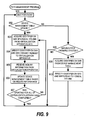
- Fig. 9 is a flowchart showing the process of the path management program 125 of the first embodiment of this invention.
- the path management program 125 Upon starting execution, the path management program 125 waits for an event (Step 901).
- the path management program 125 determines whether or not the occurring event is the device management table update event (Step 902).
- the device management table update event is an event that triggers the update of the device management table 127.
- a timer not shown
- the path management program 125 detects the notification as the device management table update event.
- the path management program 125 may detect an interruption that occurs in the SAN interface 172 when the state on the SAN 17 changes, such as when the logical volume 131 is created, deleted or migrated, as the device management table update event.
- the path management program 125 detects the error as the device management table update event.
- Step 902 when it is determined that the occurring event is the device management table update event, that is when the timing of periodically updating the device management table 127 comes, or when the state on the SAN 17 is changed (more specifically, the logical volume 131 is created, deleted or migrated, etc.).
- the path management program 125 acquires the identifier on SAN of the logical volume 131 from the virtualization apparatus 13 or a name management server (not shown) (Step 903).
- the name management server is a server that manages the identifiers on SAN of the apparatuses present on the SAN 17, and that provides a list of the identifiers on SAN according to the request.
- the computer system of the embodiment may include such a name management server.
- the path management program 125 specifies the acquired identifier on SAN and issues (sends) the inquiry request to the virtualization apparatus 13 (Step 904).
- Fig. 8 shows the process that the inquiry responding program of the virtualization apparatus 13 having received this inquiry request executes.
- the path management program 125 receives the inquiry information 400 from the virtualization apparatus 13 (Step 905).
- the path management program 125 refers to the inquiry information 400 received from the virtualization apparatus 13, and updates the device management table 127 (Step 906). More specifically, the path management program 125 registers the apparatus identifier 401 and volume number 402 of the received inquiry information 400 for the apparatus identifier 501 and volume number 502 of the entry corresponding to the specified identifier on SAN 504, respectively.
- the path management program 125 determines whether or not it has completed the update of the device management table 127 for all of the logical volumes of the virtualization apparatuses 13 (Step 907).
- Step 907 When it is determined that it has completed the update of the device management table 127 for all of the logical volumes 131 of the virtualization apparatuses 13 in Step 907, the process returns to Step 901 and waits for the next event.
- Step 907 when it is determined that it has not completed the update of the device management table 127 for all of the logical volumes 131 of the virtualization apparatuses 13, the process returns to Step 903 in order to update the device management table 127 for the next logical volume 131.
- Step 902 when it is determined that the occurring event is not the device management table update event, the path management program 125 determines whether or not the occurring event is the input/output request from the FS 124 (Step 908).
- the path management program 125 refers to the device management table 127 and acquires the identifier on SAN 504(Step 909).
- the path management program 125 specifies the acquired identifier on SAN 504, and executes the writing or reading of the requested data to the logical volume 131 (Step 910).
- the path management program 125 executes Step 910, and then returns to Step 901 to wait for the next event.
- Step 908 when it is determined that the occurring event is not the input/output request from the FS 124, the path management program 125 returns to Step 901 and waits for the next event.
- the host computer 12 When VOL-B has migrated to VOL-C, the host computer 12 attempts to access VOL-B and fails, thereby the path management program 125 detects the device management table update event (Step 902).
- the path management program 125 acquires the identifier on SAN (Step 903), and sends the inquiry request relative to VOL-C of the virtualization apparatus 13B (Step 904).
- the path management program 125 receives the inquiry information 400 (Step 905).
- the inquiry responding program 136 has created the inquiry information 400 composed of "U2" and "VOL-C” for the inquiry request relative to VOL-C of the virtualization apparatus 13B.
- the inquiry responding program 136 creates the inquiry information 400 composed of "U1" and "VOL-B” for the inquiry request relative to VOL-C of the virtualization apparatus 13B. This is identical to the inquiry information 400 created when the inquiry request relative to the migration source VOL-B is issued before VOL-B migrates to VOL-C (see Fig. 8).
- the path management program 125 updates the device management table 127 based on the received inquiry information 400 (Step 906).
- the virtual device name 503 "/dev/dsk/vo10002" is given to VOL-B before migration.
- "U1" and "VOL-B" that the path management program 125 received as the inquiry information 400 in Step 906 are the same as those of the inquiry information 400 relating to the migration sources VOL-B.
- the path management program 125 recognizes that VOL-C is the same logical volume 131 as VOL-B, and continuously gives the virtual device name 503 "dev/dsk/vo10002" to "U1" and "VOL-B".
- the path management program 125 updates the identifier on SAN 504 corresponding to these, to the value corresponding to the actual VOL-C.
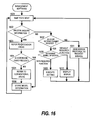
- Fig. 10 is a flowchart showing the process of the file system (FS) 124 of the first embodiment of this invention.
- the FS 124 first receives the file open request with the filename specified from the AP 123 (Step 1001).
- the FS 124 refers to the mount table 126, and identifies which virtual device stores the requested file (Step 1002). More specifically, the FS 124 searches the first character string identical to that of the specified filename from the filename first character string 602. For example, when the filename specified in Step 1001 is "/home2/testuser/filel.txt", the FS 124 identifies the virtual device having the filename first character string 602 of "/home2" (i.e. the device having the virtual device name 601 of "dev/dsk/vo10002").
- the FS 124 reads the information about correspondence between the filename and the file position from the identified virtual device (Step 1003). This information is included in the data on the identified virtual device.
- Step 1004 the FS 124 determines whether or not the reading of Step 1003 is successful.
- Step 1004 the FS 124 returns a file handle (not shown) to the AP 123 (Step 1005).
- the file handle is the management number of the file.
- the AP 123 can subsequently execute the reading and writing to the file using this file handle.
- Step 1004 when it is determined that the reading is failed, the FS 124 returns an error to the AP 123 (Step 1007).
- the FS 124 executes Step 1005 or Step 1007, and then waits for the next request from the AP 123 (Step 1006).
- the process returns to Step 1001.
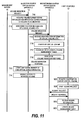
- Fig. 11 is a sequence diagram showing the procedure of the migration of the logical volume 131 in the first embodiment of this invention.
- Fig. 11 shows the correlation between the processes that the logical volume management program 137 of the migration source virtualization apparatus 13 (hereinafter referred to as the migration source logical volume management program 137), the logical volume management program 137 of the migration destination virtualization apparatus 13 (hereinafter referred to as the migration destination logical volume management program 137), and the path management program 125 of the host computer 12 execute when the logical volume 131 is migrated.
- the steps shown in Fig. 11 correspond to the steps shown in Figs. 7D, 7E, and 9, respectively. Thus, the detailed description about the individual steps will be omitted. Further, Fig. 11 is for explaining the correlation between the processes that the individual programs execute, so that the illustration about the steps unnecessary for the explanation will be omitted.
- the migration source logical volume management program 137 receives the volume migration request from the management server 16, and acquires the volume number 301 within virtualization apparatus corresponding to the logical volume 131 to be migrated (Step 710).
- the migration source logical volume management program 137 sends the configuration information of the logical volume 131, the unit serial number of own virtualization apparatus, and the volume number 301 within virtualization apparatus acquired in Step 710, to the migration destination logical volume management program 137 (Step 711).
- the unit serial number of own virtualization apparatus and the volume number 301 within virtualization apparatus are the identification information of the logical volume 131 to be migrated.
- the migration destination logical volume management program 137 receives the identification information or the like of the logical volume 131 (Step 715), and refers to the received information to configure a new logical volume 131 (Step 716).
- the migration destination logical volume management program 137 assigns one entry of the logical volume management table 138 to the newly configured logical volume 131 (Step 717).
- the migration destination logical volume management program 137 sends the volume migration response to the migration source logical volume management program 137 (Step 718).
- the migration source logical volume management program 137 receives the response, and registers the unit serial number of own virtualization apparatus for the unit serial number 302 of creation source virtualization apparatus of the logical volume management table 138 (Step 713).
- the migration source logical volume management program 137 prohibits the access to the migrated logical volume 131 (Step 714).
- the path management program 125 of the host computer 12 detects, for example, that the access to the migration source logical volume 131 is not available, and then acquires the identifier on SAN of the logical volume 131 (Step 903).
- the path management program 125 specifies the acquired identifier on SAN, and sends the inquiry request to the virtualization apparatus 13 (Step 904).
- the path management program 125 receives the inquiry information 400 from the virtualization apparatus 13 (Step 905), and refers to the received inquiry information 400 to update the device management table 127 (Step 906).
- the inquiry information 400 of the migration source logical volume 131 and the inquiry information 400 of the migration destination logical volume 131 are identical to each other.
- the path management program 125 does not update the contents other than the identifier on SAN 504 in the device management table 127.
- the system administrator does not updates the correspondence between the filename and the virtual device name, the AP 123 of the host computer 12 can access the file of the migration destination logical volume 131.
- the configuration of the computer system of the second embodiment of this invention is the same as that of the first embodiment, so that the description thereof will be omitted (see Fig. 1).
- Fig. 12 is an explanatory diagram showing the outline of the second embodiment of this invention.
- VOL-C when VOL-B migrates to VOL-C, VOL-C inherits the unit serial number 302 "U1" of creation source virtualization apparatus and the volume number at creation time "VOL-B" from VOL-B.
- the inquiry information 400 needs to be unique within the computer system, so that the virtualization apparatus 13A cannot give the volume number "VOL-B" to the newly created logical volume 131.
- VOL-B after VOL-B has migrated to VOL-C, the host computer 12 continues to recognize VOL-C as VOL-B on the virtualization apparatus 13A. Thereby, even though the virtualization apparatus 13B would have a function that the virtualization apparatus 13A does not have, it cannot apply the function to VOL-C.
- the migration destination virtualization apparatus 13 returns the inherited information to the migration source virtualization apparatus 13 at an appropriate time after the migration of the logical volume 131.
- the appropriated time is, for example, when a planned shutdown of the computer system takes place. At this time, the system administrator changes the setting of the host computer 12.
- VOL-C when VOL-B migrates to VOL-C, VOL-C inherits "U1" and "VOL-B" from VOL-B. Subsequently, when the planned shutdown of the computer system takes place, the virtualization apparatus 13B returns "U1" and "VOL-B" to the virtualization apparatus 13A. More specifically, the virtualization apparatus 13B deletes "U1" and "VOL-B" that correspond to VOL-C from the logical volume management table 138.
- the host computer 12 issues the inquiry request to VOL-C, and the virtualization apparatus 13B sends the inquiry information composed of the unit serial number "U2" of the virtualization apparatus 13B and the logical volume name "VOL-C" of VOL-C.
- the path management program 125 of the host computer 12 recognizes VOL-C as the different logical volume 131 from VOL-B.
- the path management program 125 assigns, to VOL-C, a virtual device name that is different from the above name (e.g. "/dev/dsk/vol0003").
- the system administrator releases the correspondence between the virtual device name of VOL-B "/dev/dsk/vo10002" and the filename (in the example of Fig. 12, "/home2"), and updates the mount table 126 so as to newly establish the correspondence between the virtual device name of VOL-C "/dev/dsk/vo10003" and filename "/home2".
- the AP 123 of the host computer 12 can continuously access the file stored in VOL-C.
- the virtualization apparatus 13A can give the volume number "VOL-B" to the newly created logical volume 131.
- the virtualization apparatus 13B can apply its function to VOL-C.
- the logical volume management table 138, inquiry information 400, device management table 127 and mount table 126 of the embodiment are the same as those of the first embodiment of this invention, so that the description thereof will be omitted (see Figs. 3A to 6). Further, the processes that the inquiry responding program 136, path management program 125 and FS 124 of the embodiment execute are the same as those of the first embodiment of this invention, so that the description thereof will be omitted (see Figs. 8 to 10).
- Figs. 13A to 13C are flowcharts showing the processes of the logical volume management program 137 of the second embodiment of this invention.
- the logical volume management program 137 of the embodiment receives the volume number return request, volume creation request, volume deletion request or volume migration request from the management server 16, and executes the processes in response to the requests. Further, the logical volume management program 137 of the embodiment receives the volume number return request and the volume migration request from another virtualization apparatus 13, and executes the processes in response to the requests. Hereinafter, these processes will be described.
- the logical volume management program 137 Upon starting execution, the logical volume management program 137 waits for an event (Step 701 of Fig. 13A).
- the logical volume management program 137 receives any of the requests with an event occurring, and determines whether or not the received request is the volume number return request the management server 16 has issued (Step 1301).
- Step 1301 when it is determined that the received request is the volume number return request that the management server 16 has issued, the logical volume management program 137 refers to the logical volume management table 138, and acquires the unit serial number 302 of creation source virtualization apparatus corresponding to the volume number to be returned (Step 1303 of Fig. 13B).
- the volume number to be returned is a volume number specified by the volume number return request.
- the logical volume management program 137 sends the volume number to be returned to the creation source virtualization apparatus 13 (Step 1304).
- Step 1305 the logical volume management program 137 waits for a response from the creation source virtualization apparatus 13 (Step 1305). This response is to be sent in Step 1308 of Fig. 13C that will be described below.
- the logical volume management program 137 receives the response from the creation source virtualization apparatus 13, and deletes, from the logical volume management table 138, the unit serial number 302 of creation source virtualization apparatus corresponding to the volume number to be returned (Step 1306).
- the logical volume management program 137 executes Step 1306, and then returns to Step 701 of Fig. 13A.
- Step 1301 when it is determined that the received request is not the volume number return request that the management server 16 has issued, the logical volume management program 137 determines whether or not the received request is the volume number return request that another virtualization apparatus 13 has issued (Step 1302).
- Step 1302 when the received request is the volume number return request that another virtualization apparatus 13 has issued, the logical volume management program 137 refers to the logical volume management table 138, and deletes the entry corresponding to the volume number to be returned (Step 1307 of Fig. 13C).
- the logical volume management program 137 sends the response indicating the completion of the volume number return, to the virtualization apparatus 13 having issued the volume number return request (Step 1308).
- the logical volume management program 137 executes Step 1308, and then returns to Step 701 of Fig. 13A.
- Step 1302 when it is determined that the received request is not the volume number return request that another virtualization apparatus has issued, the logical volume management program 137 proceeds to Step 702.
- Steps 702 to 718 are the same as those of the first embodiment of this invention, so that the description thereof will be omitted (see Figs. 7A to 7E).
- VOL-B of the virtualization apparatus 13A has migrated to VOL-C of the virtualization apparatus 13B. Further, VOL-C is inheriting "U1" and "VOL-B" from VOL-B (see Fig. 12).
- the logical volume management program 137 of the virtualization apparatus 13B receives the volume number return request with the volume number "VOL-B" specified as the return target, from the management server 16 (Step 1301).
- the logical volume management program 137 of the virtualization apparatus 13B refers to the logical volume management table 138 (see Fig. 3B).
- the value of the unit serial number 302 of creation source virtualization apparatus corresponding to the value "VOL-B" of the volume number 303 at creation time is "U1".
- the logical volume management program 137 acquires "U1" as the value of the unit serial number 302 of creation source virtualization apparatus corresponding to the volume number to be returned "VOL-B" (Step 1303).
- the logical volume management program 137 of the virtualization apparatus 13B sends the volume number to be returned "VOL-B" to the creation source virtualization apparatus 13A, and waits for the response (Steps 1304 and 1305).
- the logical volume management program 137 of the virtualization apparatus 13A Upon receiving this volume number to be returned "VOL-B", the logical volume management program 137 of the virtualization apparatus 13A deletes the entry with the virtualization apparatus volume number 301 "VOL-B" from the logical volume management table 138 (see Fig. 3A) (Step 1307). Next, the logical volume management program 137 of the virtualization apparatus 13A sends the response to the virtualization apparatus 13B (Step 1308).
- the logical volume management program 137 of the virtualization apparatus 13B receives the response from the virtualization apparatus 13A, and deletes the value "U1" of the unit serial number 302 of creation source virtualization apparatus corresponding to the volume number to be returned "VOL-B", from the logical volume management table 138.
- the inquiry responding program 136 creates the inquiry information composed of the unit serial number "U2" of the virtualization apparatus 13B and the logical volume name "VOL-C" of VOL-C (see Steps 803 and 804 of Fig. 8).
- the logical volume management table 138 of the virtualization apparatus 13A has no entry in which the virtualization apparatus volume number 301 is "VOL-B". Thereby, the virtualization apparatus 13A can give the volume number "VOL-B" to the newly created logical volume 131.
- the configuration of the computer system in the third embodiment of this invention is the same as that of the first embodiment, so that the description thereof will be omitted (see Fig. 1).
- Fig. 14 is an explanatory diagram showing the outline of the third embodiment of this invention.
- the inquiry responding program 136 creates the inquiry information 400 using the inherited information.
- the inquiry responding program 136 creates the inquiry information 400 using the unit serial number of the own virtualization apparatus and the volume number of the logical volume 131.
- the path management program 125 refers to the inquiry information 400 that the inquiry responding program 136 created, and assigns the virtual device name 503 to the logical volume 131.
- the host computer 12 has management software 128 other than the path management program 125 and the management software 128 refers to the inquiry information 400.
- the management software 128 is a program that the memory 122 of the host computer 12 stores and the CPU 121 executes.
- the management software 128 of the embodiment is the program for changing the setting of the virtualization apparatuses 13.
- the management software 128 may include another function of managing the virtualization apparatuses 13.
- the path management program 125 is also the program that manages the virtualization apparatuses, so that it can be categorized as one kind of management software.
- the management software 128 of the embodiment is the management software other than the path management program 125.
- the management software 128 executes the setting change of the virtualization apparatus 13, so that the relevant virtualization apparatus may need to have a specific function.
- the specific function for example, is a function that dynamically changes the capacity of the logical volume 131 the virtualization apparatus 13 manages.
- the management software 128 refers to the model information included in the unit serial number within the inquiry information 400, and determines whether or not the virtualization apparatus 13 with the setting to be changed includes the required function. When it is determined that the virtualization apparatus 13 does not include the required function, the management software 128 does not execute the setting change.
- the virtualization apparatus 13A is an old model not including the required function
- the virtualization apparatus 13B is a new model including the required function.
- the inquiry information 400 created with respect to the logical volume 131 of the virtualization apparatus 13B includes the unit serial number "U1" of the virtualization apparatus 13A.
- the management software 128 refers to the unit serial number "U1", and determines that the virtualization apparatus 13B is the old model. As a result, the management software 128 cannot execute the setting change in the virtualization apparatus 13B.
- the management software 128 cannot execute the setting change in the virtualization apparatus 13B until the "U1" is returned from VOL - C to the virtualization apparatus 13A (see Fig. 12 and the other related figures).
- inquiry information 1400 of the third embodiment of this invention includes the inherited unit serial number. Further, the inquiry information 1400 of the embodiment includes the unit serial number of the virtualization apparatus 13 having received the inquiry request.
- inquiry information 1400 of the embodiment will be described with reference to Fig. 14.
- Fig. 14 shows the inquiry information 1400 that the inquiry responding program 136 of the virtualization apparatus 13B of the embodiment creates and sends, when the host has issued the inquiry request relative to VOL-C of the virtualization apparatus 13B.
- VOL-C is the migration destination of VOL-B of the virtualization apparatus 13A.
- VOL-C is inheriting the unit serial number "U1" of the virtualization apparatus 13A and the volume number "VOL-B" of VOL-B.
- the inquiry information 1400 of the embodiment includes at least four areas of areas 1401 to 1404.
- the area 1401 is the same as the area in which the unit serial number of the virtualization apparatus 13 is registered in the conventional inquiry information.
- the area 1401 is also the same as the area in which the unit serial number of the virtualization apparatus 13 (i.e. the apparatus identifier 401) is registered in the first and second embodiments of this invention.
- the area 1402 is the same as the area in which the volume number of the logical volume 131 is registered in the conventional inquiry information.
- the area 1402 is also the same as the area in which the volume number of the logical volume 131 (i.e. the volume number 402) is registered in the first and second embodiments of this invention.
- Registered in the areas 1401 and 1402 of the embodiment is the same information as that of the first and second embodiments.
- the unit serial number 302 of creation source virtualization apparatus and the volume number 303 at creation time are registered in the areas 1401 and 1402 respectively.
- the unit serial number of the virtualization apparatus 13 for storing the logical volume 131 and the volume number 301 within virtualization apparatus of the logical volume 131 are registered in the areas 1401 and 1402 respectively.
- VOL-C is inheriting the unit serial number "U1" and the volume number "VOL-B".
- "U1" and "VOL-B" are registered in the areas 1401 and 1402 respectively.
- the areas 1403 and 1404 are assigned to blank areas in the conventional inquiry information.
- the areas 1403 and 1404 are blank.
- the unit serial number of the virtualization apparatus 13 for storing the logical volume 131 and the volume number 301 within virtualization apparatus of the logical volume 131 are registered in the areas 1401 and 1402 respectively.
- VOL-C is inheriting the unit serial number "U1" and other related information.
- the unit serial number "U2" of the virtualization apparatus 13B for storing VOL-C and the volume number "VOL-C" of VOL-C are registered in the areas 1403 and 1404 respectively.
- the areas 1401 and 1402 are referred to as the "conventional areas”.
- the areas 1403 and 1404 are referred to as the "extension areas”.
- the path management program 125 of the embodiment refers to the conventional areas of the inquiry information 1400.
- the AP 123 can access the file on VOL-C without changing the setting of the host computer 12.
- the management software 128 of the embodiment refers to the extension areas of the inquiry information 1400.
- the management software 128 can execute the setting change in the virtualization apparatus 13B using the function that the new model virtualization apparatus 13B includes.
- Fig. 15 is a flowchart showing the process of the inquiry responding program 136 of the third embodiment of this invention.
- Steps 801 to 809 are the same as Steps 801 to 809 in the inquiry responding program 136 of the first embodiment of this invention. Thereby, the description of these steps will be omitted. It is to be noted that the inquiry responding program 136 creates the inquiry information 1400 in Steps 804 and 806. Further, the inquiry responding program 136 sends out the inquiry information 1400 in Step 808.
- the inquiry responding program 136 of the embodiment registers the unit serial number of the virtualization apparatus 13 actually managing the logical volume 131 and the volume number of the logical volume 131 as the target of the inquiry request, in the extension areas of the inquiry information 1400 (step 1501).
- VOL-C is the migration destination of VOL-B of the virtualization apparatus 13A.
- the logical volume management table 138 of the virtualization apparatus 13B is as shown in Fig. 3B.
- the inquiry responding program 136 of the embodiment registers the unit serial number "U2" of the virtualization apparatus 13B for managing VOL-C, in the area 1403. Further, the inquiry responding program 136 registers the volume number "VOL-C" of VOL-C in the area 1404.
- Fig. 16 is a flowchart showing the process of the management software 128 of the third embodiment of this invention.
- Step 1601 Upon starting execution, the management software 128 waits for an event (Step 1601).
- the management software 128 determines whether or not the occurring event is the reception of the inquiry information (Step 1602).
- Step 1602 when the management software 128 determines that the occurring event is the reception of the inquiry information, the host computer 12 receives the inquiry information 1400.
- the inquiry information 1400 is sent as a response to the inquiry request that the host computer 12 has issued relative to any of the logical volumes 131 of either of the virtualization apparatuses 13.
- the management software 128 refers to the extension areas of the received inquiry information 1400 (Step 1603).
- the virtualization apparatus 13 as the destination of the above described inquiry request will be referred to as the "target virtualization apparatus 13"
- the logical volume 131 as the target of the inquiry request is referred to as the “target logical volume 131”.
- the management software 128 determines whether or not the extension areas are present (Step 1604). For example, the management software 128 determines that the extension areas are present with the valid values registered in the extension areas.
- Step 1604 when the management software 128 determines that the extension areas are present, the target logical volume 131 is inheriting the unit serial number and other related information from another logical volume 131.
- the unit serial number and other related information inherited from the migration source are registered in the conventional areas of the inquiry information 1400, and the unit serial number of the target virtualization apparatus 13 and the volume number of the target logical volume 131 are registered in the extension areas.
- the management software 128 reads the model information included in the unit serial number of the target virtualization apparatus 13 registered in the extension area. Then, the management software 128 stores the read model information in a predetermined area (not shown) of the host computer 12 (Step 1606).
- Step 1604 when the management software 128 determines that no extension area is present, the target logical volume 131 is not inheriting the unit serial number and other related information from another logical volume 131.
- the unit serial number of the target virtualization apparatus 13 and the volume number of the target logical volume 131 are registered in the conventional areas of the inquiry information 1400.
- the management software 128 refers to the conventional areas of the inquiry information 1400 (Step 1605). Then, the management software 128 reads the model information included in the unit serial number of the target virtualization apparatus 13 registered in the conventional area.
- the management software 128 stores the read model information in a predetermined area (not shown) of the host computer 12 (Step 1606).
- the management software 128 having stored the model information then returns to Step 1601.
- Step 1602 when the management software 128 determines that the occurring event is not the reception of the inquiry information, the management software 128 determines whether or not the occurring event is the reception of the setting change request (Step 1607).
- the management software 128 determines that the occurring event is not the reception of the setting change request in Step 1607, the management software 128 receives a request not executable. In this case, the management software 128 sends an error response to the request source (Step 1611), and returns to Step 1601.
- Step 1607 when the management software 128 determines that the occurring event is the reception of the setting change request, the management software 128 receives the setting change request relative to either of the virtualization apparatuses 13 from the user of the host computer 12 or the management server 16 and the like. In this case, the management software 128 refers to the model information stored in Step 1606 to determine the model of the virtualization apparatus 13 with the setting to be changed (Step 1608).
- Step 1608 when determining that the virtualization apparatus 13 with the setting to be changed is the model including the function required to execute the setting change, the management software 128 can execute the setting change in the virtualization apparatus 13. Thereby, the management software 128 executes the setting change (Step 1609), and returns to Step 1601.
- Step 1608 when determining that the virtualization apparatus 13 with the setting to be changed is the model not including the function required to execute the setting change, the management software 128 cannot execute the setting change in the virtualization apparatus 13. Thereby, the management software 128 displays an error (Step 1610), and returns to Step 1601.
- the management software 128 always refers to the unit serial number of the target virtualization apparatus 13 registered in the inquiry information and reads the model information of the target virtualization apparatus 13. Because of this feature, although the case in which the target logical volume 131 is inheriting the unit serial number of another virtualization apparatus 13, the management software 128 can determine whether or not the target virtualization apparatus 13 includes the predetermined function by itself. As a result, the management software 128 can execute the setting change using the function that the target virtualization apparatus 13 includes.
- the logical volume management program 137 of the first embodiment of this invention is applied to this embodiment.
- the logical volume management program 137 of the second embodiment of this invention may also be applied to this embodiment.
- the management software 128 can execute the setting change using the function that the target virtualization apparatus 13 includes, even before the target logical volume 131 returns the unit serial number of another virtualization apparatus 13.
- Fig. 17 is an illustration showing the configuration of the management server 16 in the computer system of the fourth embodiment of this invention.
- the configuration of the parts other than the management server 16 of the computer system of the embodiment is the same as that of the first embodiment, so that the description thereof will be omitted (see Fig. 1). Further, of the management server 16, the description of the same parts as those of the management server of the first embodiment will be omitted.
- the memory 162 of the management server 16 of the embodiment stores therein a logical volume creation control program 1701.
- the CPU 161 executes the logical volume creation control program 1701.
- Fig. 18 is a flowchart showing the process of the logical volume creation control program 1701 of the fourth embodiment of this invention.
- Step 1801 Upon starting execution, the logical volume creation control program 1701 waits for an event (Step 1801).
- the logical volume creation control program 1701 determines whether or not the occurring event is the reception of the logical volume creation request (Step 1802).
- Step 1802 when it is determined that the occurring event is not the reception of the logical volume creation request, the logical volume creation control program 1701 has received the request other than the logical volume creation request. In this case, the logical volume creation control program 1701 executes the requested process (Step 1805), and returns to Step 1801.
- Step 1802 when it is determined that the occurring event is the reception of the logical volume creation request, the logical volume creation control program 1701 has received the logical volume creation request. In this case, the logical volume creation control program 1701 creates a new volume number that is unique within the computer system (Step 1803).
- the logical volume creation control program 1701 issues an instruction to create a logical volume 131 using the created volume number, to the virtualization apparatus 13 (Step 1804), and returns to Step 1801.
- the virtualization apparatus 13 Upon receiving the instruction, the virtualization apparatus 13 creates a new logical volume 131 and gives the volume number created in Step 1803 to the newly created logical volume 131.
- first to fourth embodiments of this invention will be realized in the computer system having plural virtualization apparatus 13 connecting with one or more storage systems 133 via the SAN 17.
- the embodiments may also be realized by incorporating the virtualization apparatus function into the storage system.
- Fig. 19 is a block diagram of the computer system including the storage system into which the virtualization apparatus function is incorporated of the embodiment of this invention.
- Fig. 19 shows replacing one of the virtualization apparatuses 13 of the computer system shown in Fig. 1 with a storage system with virtualization function 1901.
- Fig. 19 the description of the same parts as those in Fig. 1 will be omitted. Incidentally, it is allowable to replace two or more or all of the virtualization apparatuses 13 with the storage system with virtualization function 1901.
- the storage system with virtualization function 1901 connects with the host computer 12 and the management server 16 via the LAN 15 and the SAN 17, similarly to the virtualization apparatuses 13 of Fig. 1.
- the management server 16 connects with the management console 14. In Fig. 19, the illustration of the host computer 12, the management console 14, the LAN 15 and the management server 16 is omitted.
- the storage system with virtualization function 1901 connects with the storage systems 133 via the SAN 17.
- the storage system with virtualization function 1901 includes the controller 132, the SAN interface (I/F) 172 and a disk apparatus 1902. Of these, the controller 132 and the SAN interface 172 are the same as those that the virtualization apparatus 13 of Fig. 1 includes, so that the description thereof will be omitted.
- the disk apparatus 1902 includes one or more disk drives. These disk drives may configure a disk array.
- the storage area of the disk apparatus 1902 configures one or more real volumes 139.
- the storage system with virtualization function 1901 provides, similarly to the virtualization apparatus 13, the logical volume 131 to the host computer 12.
- the logical volume 131 that the storage system with virtualization function 1901 provides may correspond to the real volume 139 on the disk apparatus 1902, or correspond to the real volume 139 on the storage system 133.
- the storage system with virtualization function 1901 may also provide the real volume 139 itself on the disk apparatus 1902 to the host computer 12, as the logical volume 131.
- the computer system including the above described storage system with virtualization function 1901 also allows to realize the first to fourth embodiments of this invention by executing the processes described in Figs. 2 to 18.
- the migration source virtualization apparatus 13 After the migration of the logical volume 131, the migration source virtualization apparatus 13 must continue to maintain the volume number of the migrated logical volume 131 in the logical volume management table 138. This allows to maintain the uniqueness of the inquiry information.
- the migration destination virtualization apparatus 13 returns the volume number inherited from the migration source virtualization apparatus 13 at an appropriate time. This allows to reuse the volume number of the migrated logical volume 131 while maintaining the uniqueness of the inquiry information.
- the fourth embodiment of this invention allows to give the unique volume numbers within the computer system that the management serer 16 creates, to all of the logical volumes 131 within the computer system.
- the volume number can be used as the identification information for uniquely identifying the logical volume 131 within the computer system without combining it with the unit serial number of the virtualization apparatus 13.
- the migration source virtualization apparatus 13 does not need to hold the volume number of the migrated logical volume 131 in order to maintain the uniqueness of the inquiry information.
- the migration destination virtualization apparatus 13 does not need to return the inherited volume number to the migration source.
Landscapes
- Engineering & Computer Science (AREA)
- Theoretical Computer Science (AREA)
- Human Computer Interaction (AREA)
- Physics & Mathematics (AREA)
- General Engineering & Computer Science (AREA)
- General Physics & Mathematics (AREA)
- Information Retrieval, Db Structures And Fs Structures Therefor (AREA)
- Memory System Of A Hierarchy Structure (AREA)
Abstract
Description
- The present application claims priority from
Japanese application JP2005-314099 filed on October 28, 2005 - The technology disclosed in this specification is relates to a computer system including one or more storage systems, and more specifically, but not exclusively, relates to a volume migration in a virtualization environment in which the storage area is virtualized.
- In a computer system in which a host computer and a storage system connect with each other via a storage area network (SAN), there is known a technology using a storage area on the storage system as a virtual volume. According to the technology disclosed in
JP 2005-115506 A - In the case of a computer system including plural virtualization apparatuses, a virtual volume that one of the virtualization apparatuses is managing may migrate to another virtualization apparatus. The volume migration is carried out by releasing the correspondence between the migration source virtual volume and the real area corresponding thereto, and by associating the real area with the migration destination virtual volume. Accordingly, the migration destination virtual volume is associated with the real area having been associated with the migration source virtual volume. However, the host recognizes that these volumes are different from each other. Thus, a system administrator needs to change the host setting so that the host recognizes that these volumes are identical to each other.
- One aspect of the invention includes a control method for a computer system including a host computer, one or more storage system, and plural virtualization apparatuses, the host computer being coupled to the plural virtualization apparatuses via a network, and the plural virtualization apparatuses being coupled to the one or more storage systems via the network, in which a first virtualization apparatus includes a first memory and manages a first logical volume to which the host computer issues an access request, and a second virtualization apparatus includes a second memory and manages a second logical volume to which the host computer issues an access request. The control method associates a first real storage area on the storage system, which has been associated with the first logical volume, with the second logical volume, and stores, in the second memory, first identification information that uniquely identifies the first logical volume within the computer system.
- With an embodiment of this invention, when the virtual volume migrates between the virtualization apparatuses and although the system administrator does not change the host setting, the host can access a file on the migration destination volume.
-
- Fig. 1 is a block diagram showing the configuration of a computer system of a first embodiment of this invention;
- Fig. 2 is an explanatory diagram showing the outline of the first embodiment of this invention;
- Fig. 3A is an explanatory diagram showing a logical volume management table of a migration source virtualization apparatus of the first embodiment of this invention;
- Fig. 3B is an explanatory diagram showing a logical volume management table of a migration destination virtualization apparatus of the first embodiment of this invention;
- Fig. 4A is an explanatory diagram showing an example of the inquiry information of the first embodiment of this invention;
- Fig. 4B is an explanatory diagram showing another example of the inquiry information of the first embodiment of this invention;
- Fig. 5 is an explanatory diagram showing a device management table of the first embodiment of this invention;
- Fig. 6 is an explanatory diagram showing a mount table of the first embodiment of this invention;
- Fig. 7A is a flowchart showing the process of a logical volume management program of the first embodiment of this invention;
- Fig. 7B is a flowchart showing the process of the logical volume management program of the first embodiment of this invention;
- Fig. 7C is a flowchart showing the process of the logical volume management program of the first embodiment of this invention;
- Fig. 7D is a flowchart showing the process of the logical volume management program of the first embodiment of this invention;
- Fig. 7E is a flowchart showing the process of the logical volume management program of the first embodiment of this invention;
- Fig. 8 is a flowchart showing the process of an inquiry responding program of the first embodiment of this invention;
- Fig. 9 is a flowchart showing the process of a path management program of the first embodiment of this invention;
- Fig. 10 is a flowchart showing the process of a file system of the first embodiment of this invention;
- Fig. 11 is a sequence diagram showing the procedure of a migration of a logical volume in the first embodiment of this invention;
- Fig. 12 is an explanatory diagram showing the outline of a second embodiment of this invention;
- Fig. 13A is a flowchart showing the process of a logical volume management program of the second embodiment of this invention;
- Fig. 13B is a flowchart showing the process of the logical volume management program of the second embodiment of this invention;
- Fig. 13C is a flowchart showing the process of the logical volume management program of the second embodiment of this invention;
- Fig. 14 is an explanatory diagram showing the outline of a third embodiment of this invention;
- Fig. 15 is a flowchart showing the process of an inquiry responding program of the third embodiment of this invention;
- Fig. 16 is a flowchart showing the process of management software of the third embodiment of this invention;
- Fig. 17 is an explanatory diagram showing the configuration of a management server in a computer system of a fourth embodiment of this invention;
- Fig. 18 is a flowchart showing the process of a logical volume creation control program of the fourth embodiment of this invention; and
- Fig. 19 is a block diagram of a computer system including a storage system into which the virtualization apparatus function is incorporated of the embodiments of this invention.
- Hereinafter, the embodiments of this invention will be described with reference to the drawings.
- Fig. 1 is a block diagram showing the configuration of a computer system of a first embodiment of this invention.
- The computer system of this embodiment includes a
virtualization apparatus 13A, avirtualization apparatus 13B, ahost computer 12, amanagement server 16, amanagement console 14, and one ormore storage systems 133. - A local area network (LAN) 15 is a communication path used for interconnecting the
management server 16, thehost computer 12, thevirtualization apparatuses - A storage area network (SAN) 17 is a communication path used for interconnecting the
host computer 12, thevirtualization apparatuses individual storage systems 133 to allow them to send and receive the data. On the SAN 17 of the embodiment, the communication is carried out, for example, based on the fibre channel (FC) protocol. - The
host computer 12, thevirtualization apparatuses virtualization apparatuses individual storage systems 133 connect with each other via the SAN 17. - The
virtualization apparatus 13A is a device that provides a storage area within thestorage system 133 as a virtualized logical volume 131 (see Fig. 2) to thehost computer 12. Thelogical volume 131 will be described below with reference to Fig. 2. - The
virtualization apparatus 13A includes acontroller 132 and a SAN interface (SAN_I/F) 172. - The
controller 132 includes aCPU 134, amemory 135, a network interface card (NIC) 151 and theSAN interface 172. - The
CPU 134 is a processor that executes programs stored in thememory 135. - The
memory 135, for example a semiconductor memory, stores various programs that theCPU 134 executes and a table to which these programs refer. Thememory 135 of the embodiment stores at least aninquiry responding program 136, a logicalvolume management program 137 and a logical volume management table 138. - The
inquiry responding program 136 is a program that, when thevirtualization apparatus 13A receives an inquiry request (INQUIRY command of SCSI, operation code 12h) from thehost computer 12, creates inquiry information and sends the created inquiry information to thehost computer 12. The inquiry information is more specifically the response information of a SCSI INQUIRY command. Preferably, it is a vendor-specific table containing a portion of Standard INQUIRY data defined by the SCSI-1 standard, or Vital product data parameters defined by the SCSI-2 standard, and more preferably, Page code 80h (Unit Serial Number page) or Page code C0h-FFh. - The inquiry request is a request that the
host computer 12 sends to thevirtualization apparatus 13A in order to acquire information (inquiry information) relating to thelogical volume 131 of thevirtualization apparatus 13A. - The inquiry information includes the information relating to the
logical volume 131. More specifically, the inquiry information includes the unit serial number of thevirtualization apparatus 13A and the logical volume number oflogical volume 131 as the identification information that uniquely identifies thelogical volume 131 within the computer system. Thehost computer 12 refers to the inquiry information to identify the individuallogical volumes 131. The inquiry information will be described in detail below (see Figs. 4A and 4B). - The logical
volume management program 137 is a program for executing such operations as the creation, deletion, renaming, migration of thelogical volume 131 in response to an instruction from themanagement server 16 and the like. - The logical volume management table 138 is a table for managing the
logical volumes 131. Registered in the logical volume management table 138 is the information relating to thelogical volumes 131 that thevirtualization apparatus 13A provides to thehost computer 12. - The programs and the table will be described below in detail.
- The
NIC 151 is an interface connecting with theLAN 15 to communicate with themanagement server 16 and other related modules. - The
SAN interface 172 is an interface connecting with theSAN 17 to communicate with thehost computer 12, thevirtualization apparatus 13B and thestorage systems 133. More specifically, theSAN interface 172 is a host bus adapter (HBA) of the fibre channel (FC). Incidentally, it is allowable to use other protocols than the FC (e.g. SCSI, iSCSI or InfiniBand) for the connection between thehost computer 12, thevirtualization apparatus 13A and thestorage systems 133. In this case, theSAN interface 172 may be the adapter corresponding to these protocols. - The configuration of the
virtualization apparatus 13B is the same as that of thevirtualization apparatus 13A. Thereby, the description about the configuration of thevirtualization apparatus 13B will be omitted. In the following description, thevirtualization apparatuses virtualization apparatus 13 when they do not specifically need to be differentiated from each other. - The
host computer 12 is a computer using the data of thelogical volume 131 that thevirtualization apparatus 13 provides (i.e. the data stored in the storage area of the storage system 133). Thehost computer 12 includes aCPU 121, amemory 122, theNIC 151 and theSAN interface 172. - The
CPU 121 is a processor for executing the programs stored in thememory 122. - The
memory 122, for example a semiconductor memory, stores various programs that theCPU 121 executes and tables to which these programs refer. Thememory 122 of the embodiment stores at least an application program (AP) 123, a file system (FS) 124, apath management program 125, a mount table 126 and a device management table 127. - The
AP 123 is a program (e.g. a database management program) that executes jobs using the files on a virtual device (not shown). The virtual device is a virtual device that theFS 124 recognizes. Thepath management program 125 described below associates one virtual device with onelogical volume 131. - The
FS 124 is a program that associates an area on the virtual device with a file read or written by theAP 123. - The
path management program 125 is a program that associates the virtual device with thelogical volume 131. - The mount table 126 is a table for managing the correspondence between the virtual device and the name of the file stored in the virtual device. More specifically, the virtual device name and the first character string of the filename given to the file on the virtual device are registered in the mount table 126. The
FS 124 refers to the mount table 126. - The device management table 127 is a table for managing the correspondence between the virtual device and the
logical volume 131. More specifically, the unit serial number of thevirtualization apparatus 13 and the logical volume name, as well as the virtual device name corresponding to them are registered in the device management table 127. Thepath management program 125 refers to and updates the device management table 127. - The
path management program 125, the mount table 126 and the device management table 127 will be described in detail below. - The
management server 16 is a computer for confirming and changing the setting of thevirtualization apparatus 13. - The
management server 16 of the embodiment includes aCPU 161, amemory 162 and theNIC 151. - The
CPU 161 is a processor for executing the programs stored in thememory 162. - The
memory 162, for example a semiconductor memory, stores various programs that theCPU 161 executes. Thememory 162 of the embodiment stores at least the programs (not shown) that issues the requests of the creation, deletion and migration of the logical volume 131 (see Fig. 7A) to thevirtualization apparatus 13. - The
management console 14 is an input/output terminal that the system administrator uses for operating the management server. - The
storage system 133 connects with thevirtualization apparatus 13 via theSAN 17. Theindividual storage system 133 can be handled at least as an independent device. Theindividual storage systems 133 may be a single disk drive, or a disk array apparatus including plural disk drives. Thestorage systems 133 each include one or more real volumes 139 (described below). The file data theAP 123 uses is stored in thereal volume 139. - Fig. 2 is an explanatory diagram showing the outline of the first embodiment of this invention.
- The outline of this invention will be described with reference to Fig. 2. The illustration of the hardware configuration shown in Fig. 1 is omitted in Fig. 2.
- In Fig. 2, the apparatus identifiers identify the
individual virtualization apparatuses 13. The apparatus identifier is, for example, the unit serial number of thevirtualization apparatus 13. In the example of Fig. 2, the unit serial number of thevirtualization apparatus 13A is "U1", and the unit serial number of thevirtualization apparatus 13B is "U2". In the following embodiments, we use the unit serial number as the apparatus identifier, but it is allowable to use any identifiers other than the unit serial number as long as the identifiers uniquely identify theindividual virtualization apparatuses 13. - Incidentally, for descriptive convenience, we use the character strings such as "U1" and "U2" as the unit serial numbers. However, the actual unit serial number may be an arbitrary character and numerical string. Further, the unit serial number may include the information (model information) that identifies the model of each individual virtualization apparatus.
- In the example of Fig. 2, the two
logical volumes 131 are initially set to thevirtualization apparatus 13A. Thelogical volume 131 is a virtual storage area corresponding to one or more real volumes 139 (described below). Thevirtualization apparatus 13 can provide one or morelogical volumes 131 to thehost computer 12. - The individual
logical volumes 131 can be identified by the logical volume numbers (identifiers). The volume numbers of the twological volumes 131 of thevirtualization apparatus 13A are "VOL-A" and "VOL-B". Hereinafter, thelogical volume 131 with the volume number "VOL-A" is simply referred to as "VOL-A". This is the same for the otherlogical volumes 131. - The
individual virtualization apparatuses 13 give unique volume numbers within theindividual virtualization apparatuses 13 to thelogical volumes 131, respectively. The combination of the unit serial number of thevirtualization apparatus 13 and the volume number is used as the identification information that uniquely identifies each of thelogical volumes 131 within the computer system. - VOL-A and VOL-B correspond to one or more predetermined
real volumes 139, respectively. Thereal volume 139 is a volume composed of the storage area on thestorage system 133, in which the data is actually stored. - The
host computer 12 issues an access request to thelogical volume 131. The requested access is actually executed relative to thereal volume 139 corresponding to thelogical volume 131. - For example, when the
host computer 12 issues a data writing request relative to VOL-A, the data is actually stored in thereal volume 139 corresponding to VOL-A. At this time, it looks from thehost computer 12 as if the data were stored in VOL-A of thevirtualization apparatus 13A. In the following description, the fact that the data is stored in thereal volume 139 corresponding to VOL-A will be simply referred to as "the data is stored in VOL-A". This is the same for VOL-B and VOL-C. - Incidentally, the following description assumes that all of the
logical volumes 131 correspond to thereal volumes 139. However, thereal volume 139 may be recognized as thelogical volume 131 by itself. - In the example of Fig. 2, VOL-B migrates to VOL-C of the
virtualization apparatus 13B. More specifically, the correspondence between VOL-B and thereal volume 139 corresponding to VOL-B is released. Then, thereal volume 139 is newly associated with VOL-C. As a result, thereal volume 139 corresponding to VOL-C is the samereal volume 139 having corresponded to VOL-B. Thus, although VOL-B migrates to VOL-C, the data does not move. However, it looks as if the data having been stored in VOL-B had moved to VOL-C from thehost computer 12. - Such a migration of the
logical volume 131 is executed, for example, in order to disperse the access load of thevirtualization apparatus 13. For example, there is a case in which thehost computer 12 issues a large amount of access requests to VOL-A and VOL-B, while a few access requests to thelogical volume 131 of thevirtualization apparatus 13B. In such a case, the migration of VOL-B to thevirtualization apparatus 13B allows a portion of the access load of thevirtualization apparatus 13A to be dispersed to thevirtualization apparatus 13B. As a result, the data process performance of the whole computer system is improved. - Upon completion of the migration from VOL-B to VOL-C, the access to VOL-B is prohibited. At this moment, the exactly same data as the data having been stored in VOL-B is stored in VOL-C. When the file that the
AP 123 uses has been stored in VOL-B, it needs to issue to VOL-C the access request for theAP 123 in order to access the file. Conventionally, the system administrator has needed to manually update the mount table 126 to which theFS 124 refers in order to change the destination of such an access request. - More specifically, when the
host computer 12 issued an inquiry request relative to VOL-C, theconventional virtualization apparatus 13B replied the inquiry information composed of the unit serial number "U2" of thevirtualization apparatus 13B and the volume name "VOL-C" of VOL-C. Thus, although VOL-B and VOL-C were corresponding to the samereal volume 139, thepath management program 125 of thehost computer 12 recognized VOL-C as thelogical volume 131 different from VOL-B, and assigned a different virtual device name from VOL-B, to VOL-C. Thereby, the system administrator needed to release the correspondence between the virtual device name of VOL-B (in the example of Fig. 2, "/dev/dsk/vo10002") and the filename (in the example of Fig. 2, "/home2"), and to update the mount table 126 so as to newly establish the correspondence between the virtual device name of VOL-C (e.g. "dev/dsk/vo10003") and the filename "/home2". - With the first embodiment of this invention, the migration destination VOL-C inherits the unit serial number "U1" of the migration
source virtualization apparatus 13A and the logical volume name "VOL-B" of the migration source logical volume 131 (see Figs 3A and 3B). Then, thevirtualization apparatus 13B replies the inherited "U1" and "VOL-B" to the inquiry request from thehost computer 12. Because of this feature, thepath management program 125 recognizes that VOL-C is the samelogical volume 131 as VOL-B, and assigns to VOL-C the same virtual device name as that of VOL-B. As a result, although the system administrator does not update the mount table 126, theAP 123 can use the file stored in VOL-C. - Incidentally, the implementation of the embodiment requires that the inquiry information relating to the individual
logical volumes 131 be unique within the computer system. Thus, after thevirtualization apparatus 13B inherits "U1" and "VOL-B" from thevirtualization apparatus 13A, thevirtualization apparatus 13A cannot give the volume name "VOL-B" to the newly createdlogical volume 131. - Hereinafter, the tables and programs of the embodiment will be described in detail.
- Fig. 3A is an explanatory diagram of a logical volume management table 138 of the migration
source virtualization apparatus 13A in the first embodiment of this invention. - This logical volume management table 138 is a table for managing the
logical volumes 131 stored in thevirtualization apparatus 13A. The example of Fig. 3A shows the logical volume management table 138 after completion of the migration from VOL-B to VOL-C. - The logical volume management table 138 includes a
volume number 301 within virtualization apparatus, a unitserial number 302 of creation source virtualization apparatus and avolume number 303 at creation time. Of these, the unitserial number 302 of creation source virtualization apparatus and thevolume number 303 at creation time have not been included in the conventional logical volume management table, so that they are added in the embodiment of this invention. - The
volume number 301 within virtualization apparatus is the logical volume number of thelogical volume 131 stored in thevirtualization apparatus 13A. - The
virtualization apparatus 13A initially stores the twological volumes 131, VOL-A and VOL-B (see Fig. 2). At this moment, "VOL-A" and "VOL-B" are registered as thevolume numbers 301 within virtualization apparatus. Subsequently, VOL-B migrates to VOL-C, and VOL-B is deleted from thevirtualization apparatus 13A. - Conventionally, "VOL-B" has been deleted from the
volume number 301 within virtualization apparatus in association with the deletion of VOL-B. However, in the embodiment, "VOL-B" is not deleted from thevolume number 301 within virtualization apparatus. This is for preventing thevirtualization apparatus 13A from giving the volume number "VOL-B" to the newly createdlogical volume 131. Because the migration destination VOL-C inherits and uses "U1" and "VOL-B", if thevirtualization apparatus 13A gives the volume number "VOL-B" to the newly createdlogical volume 131, the inquiry information is not unique within the computer system. - When the
logical volume 131 migrates from onevirtualization apparatus 13 to anothervirtualization apparatus 13, the unit serial number of the migrationsource virtualization apparatus 13 is registered for the unitserial number 302 of creation source virtualization apparatus. This unit serial number of the migrationsource virtualization apparatus 13 is registered by being associated with the volume number of the migratedlogical volume 131. - In the example of Fig. 2, VOL-A and VOL-B of the
virtualization apparatus 13A are both created by thevirtualization apparatus 13A. In this case, the unitserial numbers 302 of creation source virtualization apparatus for VOL-A and VOL-B are initially both blank ("-"). Subsequently, VOL-B migrates to VOL-C, and VOL-B is deleted from thevirtualization apparatus 13A. At this time, the unit serial number "U1" of thevirtualization apparatus 13A is registered as the unitserial number 302 of creation source virtualization apparatus of VOL-B. - When the
logical volume 131 is the migration destination of thelogical volume 131 of anothervirtualization apparatus 13, the migration source logical volume number is stored for thevolume number 303 at creation time. - In the example of Fig. 2, neither of VOL-A nor VOL-B is the migration destination of the
logical volume 131 of anothervirtualization apparatus 13. Thus, thevolume numbers 303 at creation time for VOL-A and VOL-B are both blank ("-"). - Fig. 3B is an explanatory diagram of a logical volume management table 138 of the migration
destination virtualization apparatus 13B in the first embodiment of this invention. - This volume management table 138 is a table for managing the
logical volume 131 stored in thevirtualization apparatus 13B. The example of Fig. 3B shows the logical volume management table 138 after completion of the migration from VOL-B to VOL-C. In Fig. 3B, the description about the same parts as those in Fig. 3A will be omitted. - The
virtualization apparatus 13B stores VOL-C (see Fig. 2). Thus, "VOL-C" is registered as thevolume number 301 within virtualization apparatus. - VOL-C is a logical volume created as the migration destination of VOL-B of the
virtualization apparatus 13B. Thus, the unit serial number "U1" of the migrationsource virtualization apparatus 13A is registered as the unitserial number 302 of creation source virtualization apparatus of VOL-C. Further, the volume number "VOL-B" of the migration sourcelogical volume 131 is registered as thevolume number 303 at creation time of VOL-C. - Fig. 4A is an explanatory diagram showing an example of the inquiry information of the first embodiment of this invention.
- Fig. 4A shows
inquiry information 400 that thevirtualization apparatus 13A replies, when thehost computer 12 of Fig. 2 issues the inquiry request relative to VOL-A of thevirtualization apparatus 13A. - The
inquiry responding program 136 creates theinquiry information 400. The procedure of the process theinquiry responding program 136 executes will be described in detail below (see Fig. 8). - The
inquiry information 400 of the embodiment includes a apparatus identifier (unit serial number) 401 and avolume number 402. - In the logical volume management table 138 of the
virtualization apparatus 13A, the unitserial number 302 of creation source virtualization apparatus for VOL-A is blank (see Fig. 3A). In this case, the unit serial number "U1" of thevirtualization apparatus 13A that manages VOL-A is registered for theapparatus identifier 401, and the volume number "VOL-A" that thevirtualization apparatus 13A has given to VOL-A is registered for thevolume number 402. - Fig. 4B is an explanatory diagram showing another example of the inquiry information in the first embodiment of this invention.
- Fig. 4B shows the
inquiry information 400 that thevirtualization apparatus 13B replies when thehost computer 12 of Fig. 2 issues the inquiry request relative to VOL-C of thevirtualization apparatus 13B. In Fig. 4B, the description about the same parts as those in Fig. 4A will be omitted. - As shown in Fig. 2, the
virtualization apparatus 13B manages VOL-C. The conventionalinquiry responding program 136 registers the unit serial number "U2" of thevirtualization apparatus 13B that manages VOL-C and the volume number "VOL-C" that thevirtualization apparatus 13B has given to VOL-C, as theapparatus identifier 401 and thevolume number 402 respectively. However, theinquiry responding program 136 of the embodiment registers the unit serial number and volume number inherited from the migration source and replies to thehost computer 12. - More specifically, the logical volume management table 138 of the
virtualization apparatus 13B stores therein "U1" and "VOL-B" for the unitserial number 302 of creation source virtualization apparatus and thevolume number 303 at creation time of VOL-C, respectively (see Fig. 3B). In other words, VOL-C is thelogical volume 131 created as the migration destination of VOL-B of thevirtualization apparatus 13B. Further, "U1" and "VOL-B" are the values thevirtualization apparatus 13B has inherited from the migrationsource virtualization apparatus 13A. In this case, "U1" and "VOL-B" are registered for theapparatus identifier 401 and thevolume number 402 respectively. - Fig. 5 is an explanatory diagram showing the device management table 127 of the first embodiment of this invention.
- Fig. 5 shows the device management table 127 of the
host computer 12 shown in Fig. 2. - The
path management program 125 refers to and updates the device management table 127. The procedure of the process thepath management program 125 executes will be described below in detail (see Fig. 9). - The device management table 127 includes a apparatus identifier (unit serial number) 501, a
volume number 502, avirtual device name 503 and anidentifier 504 on SAN. - Registered for the
apparatus identifier 501 and thevolume number 502 are the values of the inquiry information that thehost computer 12 acquired by issuing the inquiry request, respectively. Thehost computer 12 acquires the unit serial number "U1" and the volume name "VOL-A" from thevirtualization apparatus 13A (see Fig. 4A). Thus, "U1" as theapparatus identifier 501 and "VOL-A" as thevolume number 502 are registered in a first entry (line) of the device management table 127. Meanwhile, thehost computer 12 acquires the unit serial number "U1" and the volume name "VOL-B" from thevirtualization apparatus 13B (see Fig. 4B). Thus, "U1" as theapparatus identifier 501 and "VOL-B" as thevolume number 502 are registered in a second entry of the device management table 127. - The
virtual device name 503 is a name used for thehost computer 12 to recognize thelogical volume 131 as the virtual device. In the example of Fig. 5, "/dev/dsk/vo10001" is registered as thevirtual device name 503 corresponding to VOL-A, and "/dev/dsk/vo10002" is registered as thevirtual device name 503 corresponding to VOL-B. - The
identifier 504 on SAN is an identifier used for identifying the individuallogical volumes 131 on theSAN 17. In the example of Fig. 5, "0x90abcdef'' is registered as the identifier onSAN 504 corresponding to VOL-A, and "0x12345678" is registered as the identifier onSAN 504 corresponding to VOL-B. - Fig. 6 is an explanatory diagram showing the mount table 126 of the first embodiment of this invention.
- Fig. 6 shows the mount table 126 of the
host computer 12 shown in Fig. 2. - The
FS 124 refers to the mount table 126. The procedure of the process theFS 124 executes will be described below in detail (see Fig. 10). - The mount table 126 includes a
virtual device name 601 and a filenamefirst character string 602. - As shown in Fig. 5, the
host computer 12 recognizes the two virtual devices. Thus, the names of the two virtual devices "/dev/dsk/vol0001" and "/dev/dsk/vo10002" are registered for thevirtual device name 601 of the mount table 126. - The filename
first character string 602 is the first character string of a filename given to a file on each virtual device. In the example of Fig. 6, "/home1" is registered as the filenamefirst character string 602 corresponding to the virtual device name "/dev/dsk/vo10001", and "/home2" is registered as the filenamefirst character string 602 corresponding to the virtual device name "/dev/dsk/vo10002". In this case, for example, the filename "/home2/testuser/filse1.txt" is given to the file on the virtual device with thevirtual device name 601 of "/dev/dsk/vo10002". Similarly, the filenames beginning with "/home2" are given to the other files on the virtual device. - The filenames beginning with "/home1" are given to the files on the virtual device with the
virtual device name 601 of "/dev/dsk/vo10001". - Next, the processes that the programs of the embodiment execute will be described with reference to the flowcharts. In the following description, the processes that the individual programs execute are actually executed by the
CPU 121 and other related modules that execute the programs. More specifically, theCPU 121 of thehost computer 12 executes the processes of theFS 124 and thepath management program 125. TheCPU 134 of thevirtualization apparatus 13 executes the processes of theinquiry responding program 136 and the logicalvolume management program 137. - Further, in the following description, the
host computer 12 and thevirtualization apparatuses 13 send and receive therebetween the inquiry request and theinquiry information 400 via theSAN interface 172 and theSAN 17. The virtualization apparatuses 13 send and receive therebetween the identification information of thelogical volume 131 via theSAN interface 172 and theSAN 17. The virtualization apparatuses 13 may also send and receive therebetween the identification information of thelogical volume 131 via theNIC 151 and theLAN 15. - Figs. 7A to 7E are flowcharts showing the processes of the logical
volume management program 137 of the first embodiment of this invention. - The logical
volume management program 137 of the embodiment, when receiving the volume creation request, volume deletion request or volume migration request from themanagement server 16, executes the processes in response to the requests. Further, the logicalvolume management program 137 of the embodiment, when receiving the volume migration request from anothervirtualization apparatus 13, executes the process in response to the request. These processes will be described below. - Upon starting execution, the logical
volume management program 137 waits for an event (Step 701 of Fig. 7A). - When receiving any of the requests with an event occurring, the logical
volume management program 137 determines whether or not the received request is the volume creation request that themanagement server 16 has issued (Step 702). - In
Step 702, when it is determined that the received request is the volume creation request that themanagement server 16 has issued, the logicalvolume management program 137 creates the requested logical volume 131 (Step 706 of Fig. 7B). More specifically, the logicalvolume management program 137 secures thereal volume 139 corresponding to thelogical volume 131 that is the target of the creation request, on thestorage system 133, and associates thereal volume 139 with thelogical volume 131. Incidentally, the area on thereal volume 139 corresponding to the logical volume may be one or more of the entirereal volumes 139, or may be a partial area of thereal volume 139 or a group of the partial areas thereof. - Next, the logical
volume management program 137 assigns an entry (a line) of the logical volume management table 138 to the created logical volume 131 (Step 707). At this time, the volume number newly given to the createdlogical volume 131 is registered for thevolume number 301 within virtualization apparatus. At this moment, the unitserial number 302 of creation source virtualization apparatus andvolume number 303 at creation time corresponding to the createdlogical volume 131 are both blank. - For example, the logical
volume management program 137 of thevirtualization apparatus 13A, when receiving the request to create VOL-A, secures thereal volume 139 corresponding to VOL-A, and associates thereal volume 139 with VOL-A (Step 706). Then, the logicalvolume management program 137 assigns an entry of the logical volume management table 138 to VOL-A (Step 707). At this time, the unitserial number 302 of creation source virtualization apparatus andvolume number 303 at creation time corresponding to VOL-A are both blank (see Fig. 3A). - The logical
volume management program 137 executesStep 707, and then returns to Step 701. - On the other hand, in
Step 702, when it is determined that the received request is not the volume creation request that themanagement server 16 has issued, the logicalvolume management program 137 determines whether or not the received request is the volume deletion request that themanagement server 16 has issued (Step 703). - In
Step 703, when it is determined that the received request is the volume deletion request that themanagement server 16 has issued, the logicalvolume management program 137 deletes the entry corresponding to thelogical volume 131 that is the target of the deletion request, from the logical volume management table 138 (Step 708 of Fig. 7C). - Next, the logical
volume management program 137 executes the deletion of the requested logical volume 131 (Step 709). More specifically, the logicalvolume management program 137 releases the correspondence between the requestedlogical volume 131 and thereal volume 139. - The logical
volume management program 137 executesStep 709, and then returns to Step 701. - On the other hand, in
Step 703, when it is determined that the received request is not the volume deletion request themanagement server 16 has issued, the logicalvolume management program 137 determines whether or not the received request is the volume migration request that themanagement server 16 has issued (Step 704). The volume migration request that themanagement server 16 has issued is a request to migrate thelogical volume 131 to thelogical volume 131 of anothervirtualization apparatus 13. - In
Step 704, when it is determined that the received request is the volume migration request that themanagement server 16 has issued, the logicalvolume management program 137 refers to the logical volume management table 138, and acquires thevolume number 301 within virtualization apparatus corresponding to thelogical volume 131 to be migrated (Step 710 of Fig. 7D). - Next, the logical
volume management program 137 sends the configuration information of thelogical volume 131, the unit serial number of the own virtualization apparatus, and thevolume number 301 within virtualization apparatus acquired inStep 710, to the migration destination virtualization apparatus 13 (Step 711). Herein, the configuration information of thelogical volume 131 includes information indicating the correspondence between thelogical volume 131 to be migrated and thereal volume 139 in which the data written in thelogical volume 131 is actually stored. Further, the unit serial number of the own virtualization apparatus is the unit serial number of the migration source virtualization apparatus 13 (i.e. thevirtualization apparatus 13 to be the source of the information in Step 711). The logicalvolume management program 137 sends these pieces of information to the migrationdestination virtualization apparatus 13 as the volume migration request. - Next, the logical
volume management program 137 waits for the response from the migration destination virtualization apparatus 13 (Step 712). This response is sent inStep 718 of Fig. 7E described below. The transmission of this response indicates the completion of the migration of thelogical volume 131. - The logical
volume management program 137 receives the response from the migrationdestination virtualization apparatus 13, and then registers the unit serial number of the own virtualization apparatus for the unitserial number 302 of creation source virtualization apparatus of the logical volume management table 138 corresponding to the migrated logical volume 131 (Step 713). The migratedlogical volume 131 is the same as "thelogical volume 131 to be migrated" inStep 710. - Next, the logical
volume management program 137 prohibits the access to the migrated logical volume (Step 714). - The logical
volume management program 137 executesStep 714, and then returns to Step 701. - Herein, as an example of the process of Fig. 7D, the description will be made about the case in which the logical
volume management program 137 of thevirtualization apparatus 13A receives the request to migrate VOL-B to thevirtualization apparatus 13B, from the management server 16 (Step 704). - In this case, the logical
volume management program 137 refers to the logical volume management table 138 and acquires "VOL-B" in Step 710 (see Fig. 3A). - Next, in
Step 711, the logicalvolume management program 137 sends the configuration information of VOL-B, the unit serial number "U1" of thevirtualization apparatus 13A, and "VOL-B" acquired inStep 710, to thevirtualization apparatus 13B. - The logical
volume management program 137 receives the response from thevirtualization apparatus 13B inStep 712, and then registers the unit serial number "U1" of thevirtualization apparatus 13A for the unitserial number 302 of creation source virtualization apparatus corresponding to "VOL-B" of the logical volume management table 138 in Step 713 (see Fig. 3A). - Next, the logical
volume management program 137 prohibits the access to VOL-B (Step 714), and then returns to Step 701. - On the other hand, in
Step 704, when it is determined that the received request is not the volume migration request that themanagement server 16 has issued, the logicalvolume management program 137 determines whether or not the received request is the volume migration request that anothervirtualization apparatus 13 has issued (Step 705). The volume migration request that anothervirtualization apparatus 13 has issued is a request to migrate thelogical volume 131 of anothervirtualization apparatus 13 to thelogical volume 131 of the own virtualization apparatus 13 (i.e. thevirtualization apparatus 13 having received the request). This request is specifically the volume migration request having been sent inStep 711 of Fig. 7D. - In
Step 705, when determining that the received request is the volume migration request that anothervirtualization apparatus 13 has issued, the logicalvolume management program 137 receives the configuration information of thelogical volume 131, the unit serial number of the migrationsource virtualization apparatus 13, and thevolume number 301 within virtualization apparatus (Step 715). These pieces of information are the ones sent inStep 711 of Fig. 7D. - Next, the logical
volume management program 137 configures a new logical volume 131 (Step 716). More specifically, the logicalvolume management program 137 refers to the configuration information of thelogical volume 131 received inStep 715, and associates thereal volume 139 corresponding to the migration sourcelogical volume 131 with the newly createdlogical volume 131. - Next, the logical
volume management program 137 assigns one entry of the logical volume management table 138 to the newly configured logical volume 131 (Step 717). At this time, the volume number given to the newly configured logical volume is stored for thevolume number 301 within virtualization apparatus of the entry. The unit serial number of the migrationsource virtualization apparatus 13 received inStep 715 is stored for the unitserial number 302 of creation source virtualization apparatus of the entry. Further, thevolume number 301 within virtualization apparatus received inStep 715 is stored for thevolume number 303 at creation time of the entry. - Next, the logical
volume management program 137 sends the volume migration response back to the migration source virtualization apparatus 13 (Step 718). This response is to notify about the completion of the migration of thelogical volume 131. - The logical
volume management program 137 executesStep 718, and then returns to Step 701. - Herein, as an example of the process of Fig. 7E, the description will be made about the case in which the logical
volume management program 137 of thevirtualization apparatus 13B receives the request to migrate VOL-B of thevirtualization apparatus 13A to thevirtualization apparatus 13B, from thevirtualization apparatus 13A (Step 705). - In this case, the logical
volume management program 137 of thevirtualization apparatus 13B receives the configuration information of VOL-B, the unit serial number "U1" of the migrationsource virtualization apparatus 13A, and the volume number within virtualization apparatus "VOL-B" inStep 715. - Next, in
Step 716, the logicalvolume management program 137 configures VOL-C as a new logical volume. VOL-C is associated with thereal volume 139 to which VOL-B has corresponded. - Next, in
Step 717, the logicalvolume management program 137 assigns one entry of the logical volume management table 138 to VOL-C. "VOL-C" for the virtualizationapparatus volume number 301, "U1" for theserial number 302 of creation source virtualization apparatus, and "VOL-B" for thevolume number 303 at creation time, respectively are stored in the entry. (see Fig. 3B). - Next, the logical
volume management program 137 sends the volume migration response back to the migrationsource virtualization apparatus 13A (Step 718), and then returns to Step 701. - Fig. 8 is a flowchart showing the process of the
inquiry responding program 136 of the first embodiment of this invention. - The
virtualization apparatus 13 receives the inquiry request relative to either of thelogical volumes 131 from thehost computer 12, and the process of theinquiry responding program 136 starts (Step 801). - Next, the
inquiry responding program 136 refers to the logical volume management table 138 (Step 802). More specifically, theinquiry responding program 136 refers to the entry corresponding to thelogical volume 131 that is the target of the inquiry request in the logical volume management table 138. - Next, the
inquiry responding program 136 determines whether or not the unitserial number 302 of creation source virtualization apparatus of the entry referred to inStep 802 is blank (Step 803). - When it is determined that the unit
serial number 302 of creation source virtualization apparatus is blank inStep 803, thelogical volume 131 corresponding to the entry is not the migration destination from thelogical volume 131 of anothervirtualization apparatus 13 or the migration source to thelogical volume 131 of anothervirtualization apparatus 13. In this case, theinquiry responding program 136 creates theinquiry information 400 with the unit serial number of the own virtualization apparatus (i.e. thevirtualization apparatus 13 including the inquiry responding program 136) as theapparatus identifier 401 and the volume number that the own virtualization apparatus given to the logical volume as the volume number 402 (Step 804). - On the other hand, in
Step 803, when it is determined that that the unitserial number 302 of creation source virtualization apparatus is not blank, thelogical volume 131 corresponding to the entry is the migration destination from thelogical volume 131 of anothervirtualization apparatus 13 or the migration source to thelogical volume 131 of anothervirtualization apparatus 13. In this case, theinquiry responding program 136 determines whether or not the unitserial number 302 of creation source virtualization apparatus of the entry referred to inStep 802 is the unit serial number of the own virtualization apparatus (Step 805). - When it is determined that the unit
serial number 302 of creation source virtualization apparatus is not the unit serial number of the own virtualization apparatus inStep 805, thelogical volume 131 corresponding to the entry is the migration destination from thelogical volume 131 of anothervirtualization apparatus 13. In this case, theinquiry responding program 136 creates theinquiry information 400 using the information inherited from the migration source logical volume 131 (Step 806). More specifically, theinquiry responding program 136 creates theinquiry information 400 with the value registered for the unitserial number 302 of creation source virtualization apparatus of the entry as theapparatus identifier 401, and the value registered for thevolume number 303 at creation time as the volume number 402 (Step 806). - On the other hand, in
Step 805, when it is determined that the unitserial number 302 of creation source virtualization apparatus is the unit serial number of the own virtualization apparatus, thelogical volume 131 corresponding to the entry is the migration source to thelogical volume 131 of anothervirtualization apparatus 13. In other words, thelogical volume 131 corresponding to the entry has already been migrated to anothervirtualization apparatus 13, and is not present in the own virtualization apparatus. In this case, theinquiry responding program 136 does not create theinquiry information 400, and sends an error response to the host computer 12 (Step 807). - The
inquiry responding program 136 creates theinquiry information 400 inStep 804 orStep 806, and sends the createdinquiry information 400 to the host computer 12 (Step 808). - As described above, the
inquiry responding program 136 completes the response to the received inquiry request. Theinquiry responding program 136 sends theinquiry information 400 inStep 808 or sends the error response inStep 807, and then waits to receive the next inquiry request from the host computer 12 (Step 809). When receiving the next inquiry request, the process of theinquiry responding program 136 returns to Step 801. - For example, when the
virtualization apparatus 13A receives the inquiry request relative to VOL-A (Step 801), theinquiry responding program 136 of thevirtualization apparatus 13A refers to the logical volume management table 138 (Fig. 3A) of thevirtualization apparatus 13A (Step 802). The unitserial number 302 of creation source virtualization apparatus of the entry relating to VOL-A of the logical volume management table 138 is blank (Step 803). Thus, theinquiry responding program 136 creates theinquiry information 400 with the unit serial number "U1" of thevirtualization apparatus 13A as theapparatus identifier 401 and the volume number "VOL-A" of VOL-A as thevolume number 402, and sends the createdinquiry information 400 to the host computer 12 (Steps 804, 808). - When the
virtualization apparatus 13A receives the inquiry request relative to VOL-B before migrating the VOL-B to VOL-C (Step 801), theinquiry responding program 136 of thevirtualization apparatus 13A refers to the logical volume management table 138 (Fig. 3A) of thevirtualization apparatus 13A (Step 802). Before the migration of VOL-B to VOL-C, the unitserial number 302 of creation source virtualization apparatus of the entry relating to VOL-B of the logical volume management table 138 is blank (Step 803). "U1" is the unit serial number of thevirtualization apparatus 13A (i.e. the own virtualization apparatus) (Step 805). Thus, theinquiry responding program 136 creates theinquiry information 400 with the unit serial number "U1" of thevirtualization apparatus 13A as theapparatus identifier 401 and the volume number "VOL-B" of VOL-B as thevolume number 402, and sends the created inquiry information to the host computer 12 (Steps 804, 808). - When the
virtualization apparatus 13A receives the inquiry request relative to VOL-B after migrating VOL-B to VOL-C (Step 801), theinquiry responding program 136 of thevirtualization apparatus 13A refers to the logical volume management table 138 (Fig. 3A) of thevirtualization apparatus 13A (Step 802). The unitserial number 302 of creation source virtualization apparatus of the entry relating to VOL-B of the logical volume management table 138 is "U1", and not blank (Step 803). "U1" is the unit serial number of thevirtualization apparatus 13A (i.e. the own virtualization apparatus) (Step 805). Thus, theinquiry responding program 136 does not create theinquiry information 400, and sends an error response to the host computer 12 (Step 807). - On the other hand, when the
virtualization apparatus 13B receives the inquiry request relative to VOL-C (Step 801), theinquiry responding program 136 of thevirtualization apparatus 13B refers to the logical volume management table 138 (Fig. 3B) of thevirtualization apparatus 13B (Step 802). The unitserial number 302 of creation source virtualization apparatus of the entry relating to VOL-C of the logical volume management table 138 is "U1" and not blank (Step 803). "U1" is not the unit serial number of thevirtualization apparatus 13B (i.e. the own virtualization apparatus) (Step 805). Thus, theinquiry responding program 136 creates theinquiry information 400 with the value "U1" registered for the unitserial number 302 of creation source virtualization apparatus as theapparatus identifier 401 and the value "VOL-B" registered for thevolume number 303 at creation time as thevolume number 402, and sends the created inquiry information to the host computer 12 (Steps 806, 808). These values are the same as those of theinquiry information 400 created when the inquiry request relative to VOL-B is issued before migrating the VOL-B to VOL-C. - Conventionally, in the case of receiving the inquiry request relative to VOL-C, the
virtualization apparatus 13B has sent the unit serial number "U2" of thevirtualization apparatus 13B and the logical volume name "VOL-C" of VOL-C as theinquiry information 400. However, as described above, thevirtualization apparatus 13B of the embodiment sends the unit serial number "U1" and logical volume name "VOL-B" that are inherited from the migration source as theinquiry information 400. - Fig. 9 is a flowchart showing the process of the
path management program 125 of the first embodiment of this invention. - Upon starting execution, the
path management program 125 waits for an event (Step 901). - When any event occurs, the
path management program 125 determines whether or not the occurring event is the device management table update event (Step 902). The device management table update event is an event that triggers the update of the device management table 127. - More specifically, there may be a case in which a timer (not shown) notifies the
path management program 125 that a predetermined period of time has passed, and thepath management program 125 detects the notification as the device management table update event. Thepath management program 125 may detect an interruption that occurs in theSAN interface 172 when the state on theSAN 17 changes, such as when thelogical volume 131 is created, deleted or migrated, as the device management table update event. There may also be a case in which, when an error is returned to the access request relative to either of the logical volumes 131 (i.e. the access to thelogical volume 131 is failed), thepath management program 125 detects the error as the device management table update event. - In
Step 902, when it is determined that the occurring event is the device management table update event, that is when the timing of periodically updating the device management table 127 comes, or when the state on theSAN 17 is changed (more specifically, thelogical volume 131 is created, deleted or migrated, etc.). In this case, thepath management program 125 acquires the identifier on SAN of thelogical volume 131 from thevirtualization apparatus 13 or a name management server (not shown) (Step 903). The name management server is a server that manages the identifiers on SAN of the apparatuses present on theSAN 17, and that provides a list of the identifiers on SAN according to the request. The computer system of the embodiment may include such a name management server. - Next, the
path management program 125 specifies the acquired identifier on SAN and issues (sends) the inquiry request to the virtualization apparatus 13 (Step 904). Fig. 8 shows the process that the inquiry responding program of thevirtualization apparatus 13 having received this inquiry request executes. - Next, the
path management program 125 receives theinquiry information 400 from the virtualization apparatus 13 (Step 905). - Next, the
path management program 125 refers to theinquiry information 400 received from thevirtualization apparatus 13, and updates the device management table 127 (Step 906). More specifically, thepath management program 125 registers theapparatus identifier 401 andvolume number 402 of the receivedinquiry information 400 for theapparatus identifier 501 andvolume number 502 of the entry corresponding to the specified identifier onSAN 504, respectively. - Next, the
path management program 125 determines whether or not it has completed the update of the device management table 127 for all of the logical volumes of the virtualization apparatuses 13 (Step 907). - When it is determined that it has completed the update of the device management table 127 for all of the
logical volumes 131 of thevirtualization apparatuses 13 inStep 907, the process returns to Step 901 and waits for the next event. - In
Step 907, when it is determined that it has not completed the update of the device management table 127 for all of thelogical volumes 131 of thevirtualization apparatuses 13, the process returns to Step 903 in order to update the device management table 127 for the nextlogical volume 131. - On the other hand, in
Step 902, when it is determined that the occurring event is not the device management table update event, thepath management program 125 determines whether or not the occurring event is the input/output request from the FS 124 (Step 908). - When it is determined that the occurring event is the input/output request from the
FS 124 inStep 908, thepath management program 125 refers to the device management table 127 and acquires the identifier on SAN 504(Step 909). - Next, the
path management program 125 specifies the acquired identifier onSAN 504, and executes the writing or reading of the requested data to the logical volume 131 (Step 910). - The
path management program 125 executesStep 910, and then returns to Step 901 to wait for the next event. - On the other hand, in
Step 908, when it is determined that the occurring event is not the input/output request from theFS 124, thepath management program 125 returns to Step 901 and waits for the next event. - Herein, as an example, the description will be made about the process the
path management program 125 executes after VOL-B has migrated to VOL-C. - When VOL-B has migrated to VOL-C, the
host computer 12 attempts to access VOL-B and fails, thereby thepath management program 125 detects the device management table update event (Step 902). - In this case, the
path management program 125 acquires the identifier on SAN (Step 903), and sends the inquiry request relative to VOL-C of thevirtualization apparatus 13B (Step 904). - Next, the
path management program 125 receives the inquiry information 400 (Step 905). Conventionally, theinquiry responding program 136 has created theinquiry information 400 composed of "U2" and "VOL-C" for the inquiry request relative to VOL-C of thevirtualization apparatus 13B. However, in the embodiment, when VOL-B has migrated to VOL-C, theinquiry responding program 136 creates theinquiry information 400 composed of "U1" and "VOL-B" for the inquiry request relative to VOL-C of thevirtualization apparatus 13B. This is identical to theinquiry information 400 created when the inquiry request relative to the migration source VOL-B is issued before VOL-B migrates to VOL-C (see Fig. 8). - Next, the
path management program 125 updates the device management table 127 based on the received inquiry information 400 (Step 906). Herein, thevirtual device name 503 "/dev/dsk/vo10002" is given to VOL-B before migration. "U1" and "VOL-B" that thepath management program 125 received as theinquiry information 400 inStep 906 are the same as those of theinquiry information 400 relating to the migration sources VOL-B. Thereby, thepath management program 125 recognizes that VOL-C is the samelogical volume 131 as VOL-B, and continuously gives thevirtual device name 503 "dev/dsk/vo10002" to "U1" and "VOL-B". Thepath management program 125 updates the identifier onSAN 504 corresponding to these, to the value corresponding to the actual VOL-C. - Fig. 10 is a flowchart showing the process of the file system (FS) 124 of the first embodiment of this invention.
- The
FS 124 first receives the file open request with the filename specified from the AP 123 (Step 1001). - Next, the
FS 124 refers to the mount table 126, and identifies which virtual device stores the requested file (Step 1002). More specifically, theFS 124 searches the first character string identical to that of the specified filename from the filenamefirst character string 602. For example, when the filename specified inStep 1001 is "/home2/testuser/filel.txt", theFS 124 identifies the virtual device having the filenamefirst character string 602 of "/home2" (i.e. the device having thevirtual device name 601 of "dev/dsk/vo10002"). - Next, the
FS 124 reads the information about correspondence between the filename and the file position from the identified virtual device (Step 1003). This information is included in the data on the identified virtual device. - Next, the
FS 124 determines whether or not the reading ofStep 1003 is successful (Step 1004). - When it is determined that the reading is successful in
Step 1004, theFS 124 returns a file handle (not shown) to the AP 123 (Step 1005). The file handle is the management number of the file. TheAP 123 can subsequently execute the reading and writing to the file using this file handle. - In
Step 1004, when it is determined that the reading is failed, theFS 124 returns an error to the AP 123 (Step 1007). - The
FS 124 executesStep 1005 orStep 1007, and then waits for the next request from the AP 123 (Step 1006). When theFS 124 receives the next request from theAP 123, the process returns to Step 1001. - Fig. 11 is a sequence diagram showing the procedure of the migration of the
logical volume 131 in the first embodiment of this invention. - Fig. 11 shows the correlation between the processes that the logical
volume management program 137 of the migration source virtualization apparatus 13 (hereinafter referred to as the migration source logical volume management program 137), the logicalvolume management program 137 of the migration destination virtualization apparatus 13 (hereinafter referred to as the migration destination logical volume management program 137), and thepath management program 125 of thehost computer 12 execute when thelogical volume 131 is migrated. The steps shown in Fig. 11 correspond to the steps shown in Figs. 7D, 7E, and 9, respectively. Thus, the detailed description about the individual steps will be omitted. Further, Fig. 11 is for explaining the correlation between the processes that the individual programs execute, so that the illustration about the steps unnecessary for the explanation will be omitted. - First of all, the migration source logical
volume management program 137 receives the volume migration request from themanagement server 16, and acquires thevolume number 301 within virtualization apparatus corresponding to thelogical volume 131 to be migrated (Step 710). - Next, the migration source logical
volume management program 137 sends the configuration information of thelogical volume 131, the unit serial number of own virtualization apparatus, and thevolume number 301 within virtualization apparatus acquired inStep 710, to the migration destination logical volume management program 137 (Step 711). The unit serial number of own virtualization apparatus and thevolume number 301 within virtualization apparatus are the identification information of thelogical volume 131 to be migrated. - The migration destination logical
volume management program 137 receives the identification information or the like of the logical volume 131 (Step 715), and refers to the received information to configure a new logical volume 131 (Step 716). - Next, the migration destination logical
volume management program 137 assigns one entry of the logical volume management table 138 to the newly configured logical volume 131 (Step 717). - Next, the migration destination logical
volume management program 137 sends the volume migration response to the migration source logical volume management program 137 (Step 718). - The migration source logical
volume management program 137 receives the response, and registers the unit serial number of own virtualization apparatus for the unitserial number 302 of creation source virtualization apparatus of the logical volume management table 138 (Step 713). - Next, the migration source logical
volume management program 137 prohibits the access to the migrated logical volume 131 (Step 714). - The
path management program 125 of thehost computer 12 detects, for example, that the access to the migration sourcelogical volume 131 is not available, and then acquires the identifier on SAN of the logical volume 131 (Step 903). - Next, the
path management program 125 specifies the acquired identifier on SAN, and sends the inquiry request to the virtualization apparatus 13 (Step 904). - The
path management program 125 receives theinquiry information 400 from the virtualization apparatus 13 (Step 905), and refers to the receivedinquiry information 400 to update the device management table 127 (Step 906). - With the embodiment, the
inquiry information 400 of the migration sourcelogical volume 131 and theinquiry information 400 of the migration destinationlogical volume 131 are identical to each other. Thereby, thepath management program 125 does not update the contents other than the identifier onSAN 504 in the device management table 127. As a result, although the system administrator does not updates the correspondence between the filename and the virtual device name, theAP 123 of thehost computer 12 can access the file of the migration destinationlogical volume 131. - Next, a second embodiment of this invention will be described.
- The configuration of the computer system of the second embodiment of this invention is the same as that of the first embodiment, so that the description thereof will be omitted (see Fig. 1).
- Fig. 12 is an explanatory diagram showing the outline of the second embodiment of this invention.
- In Fig. 12, the description about the same parts as those in Fig. 2 will be omitted.
- In the first embodiment of this invention, when VOL-B migrates to VOL-C, VOL-C inherits the unit
serial number 302 "U1" of creation source virtualization apparatus and the volume number at creation time "VOL-B" from VOL-B. In this case, theinquiry information 400 needs to be unique within the computer system, so that thevirtualization apparatus 13A cannot give the volume number "VOL-B" to the newly createdlogical volume 131. - Further, in the first embodiment, after VOL-B has migrated to VOL-C, the
host computer 12 continues to recognize VOL-C as VOL-B on thevirtualization apparatus 13A. Thereby, even though thevirtualization apparatus 13B would have a function that thevirtualization apparatus 13A does not have, it cannot apply the function to VOL-C. - In the second embodiment of this invention, the migration
destination virtualization apparatus 13 returns the inherited information to the migrationsource virtualization apparatus 13 at an appropriate time after the migration of thelogical volume 131. The appropriated time is, for example, when a planned shutdown of the computer system takes place. At this time, the system administrator changes the setting of thehost computer 12. - For example, in Fig. 12, when VOL-B migrates to VOL-C, VOL-C inherits "U1" and "VOL-B" from VOL-B. Subsequently, when the planned shutdown of the computer system takes place, the
virtualization apparatus 13B returns "U1" and "VOL-B" to thevirtualization apparatus 13A. More specifically, thevirtualization apparatus 13B deletes "U1" and "VOL-B" that correspond to VOL-C from the logical volume management table 138. - Then, the
host computer 12 issues the inquiry request to VOL-C, and thevirtualization apparatus 13B sends the inquiry information composed of the unit serial number "U2" of thevirtualization apparatus 13B and the logical volume name "VOL-C" of VOL-C. Thereby, although VOL-B and VOL-C correspond to the samereal volume 139, thepath management program 125 of thehost computer 12 recognizes VOL-C as the differentlogical volume 131 from VOL-B. When the virtual device name "/dev/dsk/vo10002" is assigned to VOL-B, thepath management program 125 assigns, to VOL-C, a virtual device name that is different from the above name (e.g. "/dev/dsk/vol0003"). - At this time, the system administrator releases the correspondence between the virtual device name of VOL-B "/dev/dsk/vo10002" and the filename (in the example of Fig. 12, "/home2"), and updates the mount table 126 so as to newly establish the correspondence between the virtual device name of VOL-C "/dev/dsk/vo10003" and filename "/home2".
- As a result, the
AP 123 of thehost computer 12 can continuously access the file stored in VOL-C. Thevirtualization apparatus 13A can give the volume number "VOL-B" to the newly createdlogical volume 131. In addition, thevirtualization apparatus 13B can apply its function to VOL-C. - Hereinafter, the embodiment will be described in detail.
- The logical volume management table 138,
inquiry information 400, device management table 127 and mount table 126 of the embodiment are the same as those of the first embodiment of this invention, so that the description thereof will be omitted (see Figs. 3A to 6). Further, the processes that theinquiry responding program 136,path management program 125 andFS 124 of the embodiment execute are the same as those of the first embodiment of this invention, so that the description thereof will be omitted (see Figs. 8 to 10). - Figs. 13A to 13C are flowcharts showing the processes of the logical
volume management program 137 of the second embodiment of this invention. - The logical
volume management program 137 of the embodiment receives the volume number return request, volume creation request, volume deletion request or volume migration request from themanagement server 16, and executes the processes in response to the requests. Further, the logicalvolume management program 137 of the embodiment receives the volume number return request and the volume migration request from anothervirtualization apparatus 13, and executes the processes in response to the requests. Hereinafter, these processes will be described. - Incidentally, in Figs. 13A to 13C, the same step numbers are assigned to the same procedures as those in the logical
volume management program 137 of the first embodiment of this invention. - Upon starting execution, the logical
volume management program 137 waits for an event (Step 701 of Fig. 13A). - The logical
volume management program 137 receives any of the requests with an event occurring, and determines whether or not the received request is the volume number return request themanagement server 16 has issued (Step 1301). - In
Step 1301, when it is determined that the received request is the volume number return request that themanagement server 16 has issued, the logicalvolume management program 137 refers to the logical volume management table 138, and acquires the unitserial number 302 of creation source virtualization apparatus corresponding to the volume number to be returned (Step 1303 of Fig. 13B). The volume number to be returned is a volume number specified by the volume number return request. - Next, the logical
volume management program 137 sends the volume number to be returned to the creation source virtualization apparatus 13 (Step 1304). - Next, the logical
volume management program 137 waits for a response from the creation source virtualization apparatus 13 (Step 1305). This response is to be sent inStep 1308 of Fig. 13C that will be described below. - The logical
volume management program 137 receives the response from the creationsource virtualization apparatus 13, and deletes, from the logical volume management table 138, the unitserial number 302 of creation source virtualization apparatus corresponding to the volume number to be returned (Step 1306). - The logical
volume management program 137 executesStep 1306, and then returns to Step 701 of Fig. 13A. - On the other hand, in
Step 1301, when it is determined that the received request is not the volume number return request that themanagement server 16 has issued, the logicalvolume management program 137 determines whether or not the received request is the volume number return request that anothervirtualization apparatus 13 has issued (Step 1302). - In
Step 1302, when the received request is the volume number return request that anothervirtualization apparatus 13 has issued, the logicalvolume management program 137 refers to the logical volume management table 138, and deletes the entry corresponding to the volume number to be returned (Step 1307 of Fig. 13C). - Next, the logical
volume management program 137 sends the response indicating the completion of the volume number return, to thevirtualization apparatus 13 having issued the volume number return request (Step 1308). The logicalvolume management program 137 executesStep 1308, and then returns to Step 701 of Fig. 13A. - On the other hand, in
Step 1302, when it is determined that the received request is not the volume number return request that another virtualization apparatus has issued, the logicalvolume management program 137 proceeds to Step 702. - Hereinafter, the processes from
Steps 702 to 718 are the same as those of the first embodiment of this invention, so that the description thereof will be omitted (see Figs. 7A to 7E). - Incidentally, in the case in which the logical
volume management program 137 of the embodiment executes the processes shown in Figs. 7B to 7E and completes them, the processes return to Step 701 of Fig. 13A. - Herein, a specific example of the processes of Figs. 13B and 13C will be described. In the example, VOL-B of the
virtualization apparatus 13A has migrated to VOL-C of thevirtualization apparatus 13B. Further, VOL-C is inheriting "U1" and "VOL-B" from VOL-B (see Fig. 12). - First of all, the logical
volume management program 137 of thevirtualization apparatus 13B receives the volume number return request with the volume number "VOL-B" specified as the return target, from the management server 16 (Step 1301). - Next, the logical
volume management program 137 of thevirtualization apparatus 13B refers to the logical volume management table 138 (see Fig. 3B). In the logical volume management table 138, the value of the unitserial number 302 of creation source virtualization apparatus corresponding to the value "VOL-B" of thevolume number 303 at creation time is "U1". Thereby, the logicalvolume management program 137 acquires "U1" as the value of the unitserial number 302 of creation source virtualization apparatus corresponding to the volume number to be returned "VOL-B" (Step 1303). - Next, the logical
volume management program 137 of thevirtualization apparatus 13B sends the volume number to be returned "VOL-B" to the creationsource virtualization apparatus 13A, and waits for the response (Steps 1304 and 1305). - Upon receiving this volume number to be returned "VOL-B", the logical
volume management program 137 of thevirtualization apparatus 13A deletes the entry with the virtualizationapparatus volume number 301 "VOL-B" from the logical volume management table 138 (see Fig. 3A) (Step 1307). Next, the logicalvolume management program 137 of thevirtualization apparatus 13A sends the response to thevirtualization apparatus 13B (Step 1308). - The logical
volume management program 137 of thevirtualization apparatus 13B receives the response from thevirtualization apparatus 13A, and deletes the value "U1" of the unitserial number 302 of creation source virtualization apparatus corresponding to the volume number to be returned "VOL-B", from the logical volume management table 138. - Subsequently, when the
virtualization apparatus 13B receives the inquiry request relative to VOL-C, since the unitserial number 302 of creation source virtualization apparatus corresponding to VOL-C is blank, theinquiry responding program 136 creates the inquiry information composed of the unit serial number "U2" of thevirtualization apparatus 13B and the logical volume name "VOL-C" of VOL-C (seeSteps - On the other hand, the logical volume management table 138 of the
virtualization apparatus 13A has no entry in which the virtualizationapparatus volume number 301 is "VOL-B". Thereby, thevirtualization apparatus 13A can give the volume number "VOL-B" to the newly createdlogical volume 131. - Next, a third embodiment of this invention will be described.
- The configuration of the computer system in the third embodiment of this invention is the same as that of the first embodiment, so that the description thereof will be omitted (see Fig. 1).
- Fig. 14 is an explanatory diagram showing the outline of the third embodiment of this invention.
- In Fig. 14, the description of the same parts as those in Fig. 2 will be omitted.
- In the first embodiment of this invention, when the
logical volume 131 inherits the unit serial number of thevirtualization apparatus 13 and the volume number from anotherlogical volume 131, theinquiry responding program 136 creates theinquiry information 400 using the inherited information. When thelogical volume 131 does not inherit the unit serial number of thevirtualization apparatus 13 and other related information from anotherlogical volume 131, theinquiry responding program 136 creates theinquiry information 400 using the unit serial number of the own virtualization apparatus and the volume number of thelogical volume 131. - The
path management program 125 refers to theinquiry information 400 that theinquiry responding program 136 created, and assigns thevirtual device name 503 to thelogical volume 131. - However, there may be the case in which the
host computer 12 hasmanagement software 128 other than thepath management program 125 and themanagement software 128 refers to theinquiry information 400. - The
management software 128 is a program that thememory 122 of thehost computer 12 stores and theCPU 121 executes. Themanagement software 128 of the embodiment is the program for changing the setting of thevirtualization apparatuses 13. However, themanagement software 128 may include another function of managing thevirtualization apparatuses 13. - It should be noted that the
path management program 125 is also the program that manages the virtualization apparatuses, so that it can be categorized as one kind of management software. Themanagement software 128 of the embodiment is the management software other than thepath management program 125. - The
management software 128 executes the setting change of thevirtualization apparatus 13, so that the relevant virtualization apparatus may need to have a specific function. The specific function, for example, is a function that dynamically changes the capacity of thelogical volume 131 thevirtualization apparatus 13 manages. In such a case, themanagement software 128 refers to the model information included in the unit serial number within theinquiry information 400, and determines whether or not thevirtualization apparatus 13 with the setting to be changed includes the required function. When it is determined that thevirtualization apparatus 13 does not include the required function, themanagement software 128 does not execute the setting change. - For example, in Fig. 2, there may be the case in which the
virtualization apparatus 13A is an old model not including the required function, and thevirtualization apparatus 13B is a new model including the required function. When the first embodiment of this invention is applied to such a case, theinquiry information 400 created with respect to thelogical volume 131 of thevirtualization apparatus 13B includes the unit serial number "U1" of thevirtualization apparatus 13A. Then, themanagement software 128 refers to the unit serial number "U1", and determines that thevirtualization apparatus 13B is the old model. As a result, themanagement software 128 cannot execute the setting change in thevirtualization apparatus 13B. - Similarly, when the second embodiment of this invention is applied to the above case, the
management software 128 cannot execute the setting change in thevirtualization apparatus 13B until the "U1" is returned from VOL - C to thevirtualization apparatus 13A (see Fig. 12 and the other related figures). - In the case in which the
logical volume 131 is inheriting the unit serial number from the otherlogical volume 131,inquiry information 1400 of the third embodiment of this invention includes the inherited unit serial number. Further, theinquiry information 1400 of the embodiment includes the unit serial number of thevirtualization apparatus 13 having received the inquiry request. Hereinafter, theinquiry information 1400 of the embodiment will be described with reference to Fig. 14. - Fig. 14 shows the
inquiry information 1400 that theinquiry responding program 136 of thevirtualization apparatus 13B of the embodiment creates and sends, when the host has issued the inquiry request relative to VOL-C of thevirtualization apparatus 13B. In this example, VOL-C is the migration destination of VOL-B of thevirtualization apparatus 13A. VOL-C is inheriting the unit serial number "U1" of thevirtualization apparatus 13A and the volume number "VOL-B" of VOL-B. - The
inquiry information 1400 of the embodiment includes at least four areas ofareas 1401 to 1404. - The
area 1401 is the same as the area in which the unit serial number of thevirtualization apparatus 13 is registered in the conventional inquiry information. Thearea 1401 is also the same as the area in which the unit serial number of the virtualization apparatus 13 (i.e. the apparatus identifier 401) is registered in the first and second embodiments of this invention. - The
area 1402 is the same as the area in which the volume number of thelogical volume 131 is registered in the conventional inquiry information. Thearea 1402 is also the same as the area in which the volume number of the logical volume 131 (i.e. the volume number 402) is registered in the first and second embodiments of this invention. - Registered in the
areas logical volume 131 is inheriting the unit serial number of thevirtualization apparatus 13 and other related information from the migration source, the unitserial number 302 of creation source virtualization apparatus and thevolume number 303 at creation time are registered in theareas logical volume 131 is inheriting no unit serial number of thevirtualization apparatus 13 and other related information from the migration source, the unit serial number of thevirtualization apparatus 13 for storing thelogical volume 131 and thevolume number 301 within virtualization apparatus of thelogical volume 131 are registered in theareas - In the example of Fig. 14, VOL-C is inheriting the unit serial number "U1" and the volume number "VOL-B". Thus, "U1" and "VOL-B" are registered in the
areas - The
areas - When the
logical volume 131 is not inheriting the unit serial number of thevirtualization apparatus 13 and other related information from the migration source, theareas - When the
logical volume 131 is inheriting the unit serial number of thevirtualization apparatus 13 and other related information from the migration source, the unit serial number of thevirtualization apparatus 13 for storing thelogical volume 131 and thevolume number 301 within virtualization apparatus of thelogical volume 131 are registered in theareas - In the example of Fig. 14, VOL-C is inheriting the unit serial number "U1" and other related information. Thus, the unit serial number "U2" of the
virtualization apparatus 13B for storing VOL-C and the volume number "VOL-C" of VOL-C are registered in theareas areas areas - The
path management program 125 of the embodiment refers to the conventional areas of theinquiry information 1400. As a result, similarly to the first and second embodiments, theAP 123 can access the file on VOL-C without changing the setting of thehost computer 12. - On the other hand, the
management software 128 of the embodiment refers to the extension areas of theinquiry information 1400. As a result, themanagement software 128 can execute the setting change in thevirtualization apparatus 13B using the function that the newmodel virtualization apparatus 13B includes. - Hereinafter, the processes that the individual programs of the embodiment execute will be described.
- The processes that the
FS 124,path management program 125 andvolume management program 137 of the embodiment execute are the same as those of the first embodiment, so that the description thereof will be omitted. - Fig. 15 is a flowchart showing the process of the
inquiry responding program 136 of the third embodiment of this invention. - Of the process in the
inquiry responding program 136 of the embodiment, Steps 801 to 809 are the same asSteps 801 to 809 in theinquiry responding program 136 of the first embodiment of this invention. Thereby, the description of these steps will be omitted. It is to be noted that theinquiry responding program 136 creates theinquiry information 1400 inSteps inquiry responding program 136 sends out theinquiry information 1400 inStep 808. - Upon completion of
Step 806, theinquiry responding program 136 of the embodiment registers the unit serial number of thevirtualization apparatus 13 actually managing thelogical volume 131 and the volume number of thelogical volume 131 as the target of the inquiry request, in the extension areas of the inquiry information 1400 (step 1501). - For example, when the
virtualization apparatus 13B receives the inquiry request relative to VOL-C from thehost computer 12, VOL-C is the migration destination of VOL-B of thevirtualization apparatus 13A. In this case, the logical volume management table 138 of thevirtualization apparatus 13B is as shown in Fig. 3B. In this case, theinquiry responding program 136 of the embodiment registers the unit serial number "U2" of thevirtualization apparatus 13B for managing VOL-C, in thearea 1403. Further, theinquiry responding program 136 registers the volume number "VOL-C" of VOL-C in thearea 1404. - Fig. 16 is a flowchart showing the process of the
management software 128 of the third embodiment of this invention. - Upon starting execution, the
management software 128 waits for an event (Step 1601). - When any event occurs, the
management software 128 determines whether or not the occurring event is the reception of the inquiry information (Step 1602). - In
Step 1602, when themanagement software 128 determines that the occurring event is the reception of the inquiry information, thehost computer 12 receives theinquiry information 1400. Theinquiry information 1400 is sent as a response to the inquiry request that thehost computer 12 has issued relative to any of thelogical volumes 131 of either of thevirtualization apparatuses 13. In this case, themanagement software 128 refers to the extension areas of the received inquiry information 1400 (Step 1603). - It should be noted that, in the description of Fig. 16, the
virtualization apparatus 13 as the destination of the above described inquiry request will be referred to as the "target virtualization apparatus 13", thelogical volume 131 as the target of the inquiry request is referred to as the "targetlogical volume 131". - Next, the
management software 128 determines whether or not the extension areas are present (Step 1604). For example, themanagement software 128 determines that the extension areas are present with the valid values registered in the extension areas. - In
Step 1604, when themanagement software 128 determines that the extension areas are present, the targetlogical volume 131 is inheriting the unit serial number and other related information from anotherlogical volume 131. In other words, the unit serial number and other related information inherited from the migration source are registered in the conventional areas of theinquiry information 1400, and the unit serial number of thetarget virtualization apparatus 13 and the volume number of the targetlogical volume 131 are registered in the extension areas. - Thus, the
management software 128 reads the model information included in the unit serial number of thetarget virtualization apparatus 13 registered in the extension area. Then, themanagement software 128 stores the read model information in a predetermined area (not shown) of the host computer 12 (Step 1606). - On the other hand, in
Step 1604, when themanagement software 128 determines that no extension area is present, the targetlogical volume 131 is not inheriting the unit serial number and other related information from anotherlogical volume 131. In other words, the unit serial number of thetarget virtualization apparatus 13 and the volume number of the targetlogical volume 131 are registered in the conventional areas of theinquiry information 1400. - Thus, the
management software 128 refers to the conventional areas of the inquiry information 1400 (Step 1605). Then, themanagement software 128 reads the model information included in the unit serial number of thetarget virtualization apparatus 13 registered in the conventional area. - Next, the
management software 128 stores the read model information in a predetermined area (not shown) of the host computer 12 (Step 1606). - The
management software 128 having stored the model information then returns to Step 1601. - In
Step 1602, when themanagement software 128 determines that the occurring event is not the reception of the inquiry information, themanagement software 128 determines whether or not the occurring event is the reception of the setting change request (Step 1607). - When the
management software 128 determines that the occurring event is not the reception of the setting change request inStep 1607, themanagement software 128 receives a request not executable. In this case, themanagement software 128 sends an error response to the request source (Step 1611), and returns to Step 1601. - On the other hand, in
Step 1607, when themanagement software 128 determines that the occurring event is the reception of the setting change request, themanagement software 128 receives the setting change request relative to either of thevirtualization apparatuses 13 from the user of thehost computer 12 or themanagement server 16 and the like. In this case, themanagement software 128 refers to the model information stored inStep 1606 to determine the model of thevirtualization apparatus 13 with the setting to be changed (Step 1608). - In
Step 1608, when determining that thevirtualization apparatus 13 with the setting to be changed is the model including the function required to execute the setting change, themanagement software 128 can execute the setting change in thevirtualization apparatus 13. Thereby, themanagement software 128 executes the setting change (Step 1609), and returns to Step 1601. - On the other hand, in
Step 1608, when determining that thevirtualization apparatus 13 with the setting to be changed is the model not including the function required to execute the setting change, themanagement software 128 cannot execute the setting change in thevirtualization apparatus 13. Thereby, themanagement software 128 displays an error (Step 1610), and returns to Step 1601. - With the embodiment as described above, the
management software 128 always refers to the unit serial number of thetarget virtualization apparatus 13 registered in the inquiry information and reads the model information of thetarget virtualization apparatus 13. Because of this feature, although the case in which the targetlogical volume 131 is inheriting the unit serial number of anothervirtualization apparatus 13, themanagement software 128 can determine whether or not thetarget virtualization apparatus 13 includes the predetermined function by itself. As a result, themanagement software 128 can execute the setting change using the function that thetarget virtualization apparatus 13 includes. - As described above, the logical
volume management program 137 of the first embodiment of this invention is applied to this embodiment. However, the logicalvolume management program 137 of the second embodiment of this invention may also be applied to this embodiment. In this case, themanagement software 128 can execute the setting change using the function that thetarget virtualization apparatus 13 includes, even before the targetlogical volume 131 returns the unit serial number of anothervirtualization apparatus 13. - Next, a fourth embodiment of this invention will be described.
- Fig. 17 is an illustration showing the configuration of the
management server 16 in the computer system of the fourth embodiment of this invention. - It should be noted that the configuration of the parts other than the
management server 16 of the computer system of the embodiment is the same as that of the first embodiment, so that the description thereof will be omitted (see Fig. 1). Further, of themanagement server 16, the description of the same parts as those of the management server of the first embodiment will be omitted. - The
memory 162 of themanagement server 16 of the embodiment stores therein a logical volumecreation control program 1701. TheCPU 161 executes the logical volumecreation control program 1701. - Fig. 18 is a flowchart showing the process of the logical volume
creation control program 1701 of the fourth embodiment of this invention. - Upon starting execution, the logical volume
creation control program 1701 waits for an event (Step 1801). - When any event occurs, the logical volume
creation control program 1701 determines whether or not the occurring event is the reception of the logical volume creation request (Step 1802). - In
Step 1802, when it is determined that the occurring event is not the reception of the logical volume creation request, the logical volumecreation control program 1701 has received the request other than the logical volume creation request. In this case, the logical volumecreation control program 1701 executes the requested process (Step 1805), and returns to Step 1801. - On the other hand, in
Step 1802, when it is determined that the occurring event is the reception of the logical volume creation request, the logical volumecreation control program 1701 has received the logical volume creation request. In this case, the logical volumecreation control program 1701 creates a new volume number that is unique within the computer system (Step 1803). - Next, the logical volume
creation control program 1701 issues an instruction to create alogical volume 131 using the created volume number, to the virtualization apparatus 13 (Step 1804), and returns to Step 1801. - Upon receiving the instruction, the
virtualization apparatus 13 creates a newlogical volume 131 and gives the volume number created inStep 1803 to the newly createdlogical volume 131. - The above described first to fourth embodiments of this invention, as shown in Fig. 1, will be realized in the computer system having
plural virtualization apparatus 13 connecting with one ormore storage systems 133 via theSAN 17. However, the embodiments may also be realized by incorporating the virtualization apparatus function into the storage system. - Fig. 19 is a block diagram of the computer system including the storage system into which the virtualization apparatus function is incorporated of the embodiment of this invention.
- Fig. 19 shows replacing one of the
virtualization apparatuses 13 of the computer system shown in Fig. 1 with a storage system withvirtualization function 1901. In Fig. 19, the description of the same parts as those in Fig. 1 will be omitted. Incidentally, it is allowable to replace two or more or all of thevirtualization apparatuses 13 with the storage system withvirtualization function 1901. - The storage system with
virtualization function 1901 connects with thehost computer 12 and themanagement server 16 via theLAN 15 and theSAN 17, similarly to thevirtualization apparatuses 13 of Fig. 1. Themanagement server 16 connects with themanagement console 14. In Fig. 19, the illustration of thehost computer 12, themanagement console 14, theLAN 15 and themanagement server 16 is omitted. - Further, the storage system with
virtualization function 1901 connects with thestorage systems 133 via theSAN 17. - The storage system with
virtualization function 1901 includes thecontroller 132, the SAN interface (I/F) 172 and adisk apparatus 1902. Of these, thecontroller 132 and theSAN interface 172 are the same as those that thevirtualization apparatus 13 of Fig. 1 includes, so that the description thereof will be omitted. - The
disk apparatus 1902 includes one or more disk drives. These disk drives may configure a disk array. The storage area of thedisk apparatus 1902 configures one or morereal volumes 139. - The storage system with
virtualization function 1901 provides, similarly to thevirtualization apparatus 13, thelogical volume 131 to thehost computer 12. Thelogical volume 131 that the storage system withvirtualization function 1901 provides may correspond to thereal volume 139 on thedisk apparatus 1902, or correspond to thereal volume 139 on thestorage system 133. The storage system withvirtualization function 1901 may also provide thereal volume 139 itself on thedisk apparatus 1902 to thehost computer 12, as thelogical volume 131. - The computer system including the above described storage system with
virtualization function 1901 also allows to realize the first to fourth embodiments of this invention by executing the processes described in Figs. 2 to 18. - With the first embodiment of this invention as described above, after the migration of the
logical volume 131, the migrationsource virtualization apparatus 13 must continue to maintain the volume number of the migratedlogical volume 131 in the logical volume management table 138. This allows to maintain the uniqueness of the inquiry information. - Further, with the second embodiment of this invention, the migration
destination virtualization apparatus 13 returns the volume number inherited from the migrationsource virtualization apparatus 13 at an appropriate time. This allows to reuse the volume number of the migratedlogical volume 131 while maintaining the uniqueness of the inquiry information. - The fourth embodiment of this invention allows to give the unique volume numbers within the computer system that the
management serer 16 creates, to all of thelogical volumes 131 within the computer system. In other words, the volume number can be used as the identification information for uniquely identifying thelogical volume 131 within the computer system without combining it with the unit serial number of thevirtualization apparatus 13. - Consequently, with the fourth embodiment, the migration
source virtualization apparatus 13 does not need to hold the volume number of the migratedlogical volume 131 in order to maintain the uniqueness of the inquiry information. In addition, the migrationdestination virtualization apparatus 13 does not need to return the inherited volume number to the migration source.
Claims (19)
- A control method for a computer system including a host computer, one or more storage systems, and a plurality of virtualization apparatuses,
the host computer being coupled to the plurality of virtualization apparatuses via a network, and
the plurality of virtualization apparatuses being coupled to the one or more storage systems via the network,
a first virtualization apparatus including a first memory and managing a first logical volume to which the host computer issues an access request; and
a second virtualization apparatus including a second memory and managing a second logical volume to which the host computer issues an access request,
the control method comprising:associating a first real storage area on the storage system, which has been associated with the first logical volume, with the second logical volume, andstoring, in the second memory, first identification information that uniquely identifies the first logical volume within the computer system. - The control method according to claim 1, further comprising:sending the first identification information to the host computer from the second virtualization apparatus, after the second virtualization apparatus has received an acquisition request of the identification information of the second logical volume from the host computer.
- The control method according to claim 1 or claim 2,
wherein the first identification information includes a first apparatus identifier that uniquely identifies the first virtualization apparatus within the computer system and a first volume number that uniquely identifies the first logical volume within the first virtualization apparatus,
the control method further comprising:sending the first identification information to the second virtualization apparatus from the first virtualization apparatus,storing, in the first memory, the first apparatus identifier associating with the first volume number, andstoring, in the second memory, the first identification information sent from the first virtualization apparatus. - The control method according to claim 3, further comprising:sending the first volume number to the first virtualization apparatus from the second virtualization apparatus,deleting the first identification information from the second memory, anddeleting the first volume number and the first apparatus identifier stored by being associated with each other, from the first memory, after the first virtualization apparatus has received the first volume number.
- The control method according to claim 1, further comprising:sending the first identification information and the second identification information that uniquely identifies the second logical volume within the computer system, to the host computer from the second virtualization apparatus, after the second virtualization apparatus has received the acquisition request of the identification information of the second logical volume from the host computer.
- The control method according to any one of claims 1 to 5, further comprising:creating a first volume number that uniquely identifies the first logical volume within the computer system and the second volume number that uniquely identifies the second logical volume within the computer system,wherein the first identification information includes the first volume number.
- A virtualization apparatus coupled to a host computer via a network, the virtualization apparatus is further coupled to one or more storage systems and one or more other virtualization apparatuses via the network, comprising:an interface coupled to the network; a processor coupled to the interface; and a memory coupled to the processor,wherein the virtualization apparatus manages a logical volume to which the host computer issues an access request,
wherein the processor associates a first real storage area on the storage system, which has been associated with another logical volume that the another virtualization apparatus manages, with the logical volume, and stores, in the memory, first identification information that uniquely identifies the another logical volume within the computer system. - The virtualization apparatus according to claim 7,
wherein the processor receives an acquisition request of the identification information of the logical volume from the host computer via the interface, and sends the first identification information to the host computer via the interface. - The virtualization apparatus according to claim 7 or claim 8,
wherein the processor receives the first identification information from the another virtualization apparatus via the interface, and stores, in the memory, the first identification information. - The virtualization apparatus according to claim 9,
wherein the first identification information includes a first apparatus identifier that uniquely identifies the another virtualization apparatus within the computer system, and a first volume number that uniquely identifies the another logical volume within the another virtualization apparatus; and
wherein the processor sends the first volume number to the another virtualization apparatus via the interface, and deletes the first identification information from the memory. - The virtualization apparatus according to any one of claims 7 to 10,
wherein second identification information includes a second apparatus identifier that uniquely identifies the virtualization apparatus within the computer system, and a second volume number that uniquely identifies the logical volume within the virtualization apparatus; and
wherein the processor sends the second identification information to the another virtualization apparatus via the interface, and stores, in the memory, the second apparatus identifier associating with the second volume number. - The virtualization apparatus according to claim 11,
wherein, when receiving the second volume number from the another virtualization apparatus via the interface, the processor deletes the second volume number and the second apparatus identifier stored by being associated with each other, from the memory. - The virtualization apparatus according to any one of claims 7 to 12,
wherein the processor receives the acquisition request of the identification information of the logical volume from the host computer via the interface, and sends the first identification information and a second identification information that uniquely identifies the logical volume within the computer system to the host computer via the interface. - A computer system including a host computer, one or more storage systems, and a plurality of virtualization apparatus,
wherein the host computer is coupled to the plurality of virtualization apparatus via a network, and
the plurality of virtualization apparatuses are coupled to the one or more storage systems via the network, comprising:a first virtualization apparatusincluding a first interface coupled to the network, a first processor coupled to the first interface, and a first memory coupled to the first processor, and managing a first logical volume to which the host computer issues an access request; anda second virtualization apparatusincluding a second interface coupled to the network, a second processor coupled to the interface, and a second memory coupled to the second processor, and managing a second logical volume to which the host computer issues an access request,wherein the second processor associating a first real storage area on the storage system, which has been associated with the first logical volume, with the second logical volume, and storing, in the second memory, first identification information that uniquely identifies the first logical volume within the computer system. - The computer system according to claim 14,
wherein the second processor receives an acquisition request of the identification information of the second logical volume from the host computer, and sends the first identification information to the host computer via the second interface. - The computer system according to claim 14 or claim 15,
wherein the first identification information includes a first apparatus identifier that uniquely identifies the first virtualization apparatus within the computer system, and a first volume number that uniquely identifies the first logical volume within the first virtualization apparatus,
wherein the first processor sends the first identification information to the second virtualization apparatus via the first interface, and stores, in the first memory, the first apparatus identifier associating with the first volume number; and
wherein the second processor receives the first identification information from the first virtualization apparatus via the second interface, and stores, in the second memory, the first identification information. - The computer system according to claim 16,
wherein the second processor sends the first volume number to the first virtualization apparatus via the second interface, and deletes the first identification information from the second memory; and
wherein the first processor, when receiving the first volume number from the second virtualization apparatus via the first interface, deletes the first volume number and the first apparatus identifier stored by being associated with each other, from the first memory. - The computer system according to any one of claims 14 to 17,
wherein the second processor receives the acquisition request of the identification information of the second logical volume from the host computer via the second interface, and sends the first identification information and the second identification information that uniquely identifies the second logical volume within the computer system, to the host computer via the second interface. - The computer system according to any one of claims 14 to 18, further including a management server,
wherein the management server creates a first volume number that uniquely identifies the first logical volume within the computer system, and a second volume number that uniquely identifies the second logical volume within the computer system; and
wherein the first identification information includes the first volume number.
Applications Claiming Priority (1)
| Application Number | Priority Date | Filing Date | Title |
|---|---|---|---|
| JP2005314099A JP4852298B2 (en) | 2005-10-28 | 2005-10-28 | Method for taking over information for identifying virtual volume and storage system using the method |
Publications (2)
| Publication Number | Publication Date |
|---|---|
| EP1785831A2 true EP1785831A2 (en) | 2007-05-16 |
| EP1785831A3 EP1785831A3 (en) | 2009-06-24 |
Family
ID=37680648
Family Applications (1)
| Application Number | Title | Priority Date | Filing Date |
|---|---|---|---|
| EP06251964A Withdrawn EP1785831A3 (en) | 2005-10-28 | 2006-04-07 | Method of inheriting information identifying virtual volume and storage system using the same |
Country Status (3)
| Country | Link |
|---|---|
| US (1) | US7596676B2 (en) |
| EP (1) | EP1785831A3 (en) |
| JP (1) | JP4852298B2 (en) |
Cited By (5)
| Publication number | Priority date | Publication date | Assignee | Title |
|---|---|---|---|---|
| WO2012011157A1 (en) * | 2010-07-23 | 2012-01-26 | Hitachi, Ltd. | Data storage system and method for controlling a data storage system |
| WO2012066594A1 (en) * | 2010-11-16 | 2012-05-24 | Hitachi, Ltd. | Computer system and storage migration method |
| RU2462749C2 (en) * | 2007-06-29 | 2012-09-27 | Майкрософт Корпорейшн | Unified representation of physical and virtual images |
| WO2012147133A1 (en) * | 2011-04-27 | 2012-11-01 | Hitachi, Ltd. | Information storage system and storage system management method |
| WO2014061054A1 (en) * | 2012-10-15 | 2014-04-24 | Hitachi, Ltd. | Storage system and method of controlling storage system |
Families Citing this family (17)
| Publication number | Priority date | Publication date | Assignee | Title |
|---|---|---|---|---|
| US7681011B1 (en) * | 2006-03-30 | 2010-03-16 | Emc Corporation | Methods and apparatus for partitioning management information |
| US20080002680A1 (en) * | 2006-06-30 | 2008-01-03 | Nortel Networks Limited. | Method and system for variable viability summarization in communication networks |
| US8028062B1 (en) * | 2007-12-26 | 2011-09-27 | Emc Corporation | Non-disruptive data mobility using virtual storage area networks with split-path virtualization |
| JP5330702B2 (en) | 2008-01-31 | 2013-10-30 | 株式会社日立製作所 | Storage device system having a plurality of controller modules |
| JP5288875B2 (en) * | 2008-05-02 | 2013-09-11 | 株式会社日立製作所 | Storage system |
| JP5026375B2 (en) | 2008-09-09 | 2012-09-12 | 株式会社日立製作所 | Storage device and storage device control method |
| JP4905511B2 (en) * | 2009-06-30 | 2012-03-28 | 富士通株式会社 | Storage device control unit and control method |
| US9389895B2 (en) * | 2009-12-17 | 2016-07-12 | Microsoft Technology Licensing, Llc | Virtual storage target offload techniques |
| WO2012017493A1 (en) | 2010-08-06 | 2012-02-09 | 株式会社日立製作所 | Computer system and data migration method |
| US9292211B2 (en) | 2011-03-02 | 2016-03-22 | Hitachi, Ltd. | Computer system and data migration method |
| JP5380557B2 (en) * | 2012-01-31 | 2014-01-08 | 京セラドキュメントソリューションズ株式会社 | Electronic apparatus, image forming apparatus, and mounting method |
| WO2014068623A1 (en) * | 2012-10-31 | 2014-05-08 | Hitachi, Ltd. | Computer system and data management method |
| US20170017403A1 (en) * | 2014-06-24 | 2017-01-19 | Hitachi, Ltd. | Storage system |
| CN106919338B (en) * | 2015-12-24 | 2019-09-03 | 中国移动通信集团公司 | A Flash storage access processing method and system suitable for software-defined storage |
| JP7112437B2 (en) * | 2020-01-21 | 2022-08-03 | 株式会社日立製作所 | Storage system and data migration method |
| US12265734B2 (en) * | 2020-12-17 | 2025-04-01 | Alibaba Group Holding Limited | Storage nodes, integrated circuits and methods for storage node management |
| US12346591B2 (en) * | 2023-08-16 | 2025-07-01 | International Business Machines Corporation | Data migration between virtual tape systems using tape VOLSER conversion |
Citations (1)
| Publication number | Priority date | Publication date | Assignee | Title |
|---|---|---|---|---|
| JP2005115506A (en) | 2003-10-06 | 2005-04-28 | Hitachi Ltd | Storage system |
Family Cites Families (15)
| Publication number | Priority date | Publication date | Assignee | Title |
|---|---|---|---|---|
| US6654830B1 (en) * | 1999-03-25 | 2003-11-25 | Dell Products L.P. | Method and system for managing data migration for a storage system |
| US6826613B1 (en) * | 2000-03-15 | 2004-11-30 | 3Com Corporation | Virtually addressing storage devices through a switch |
| JP4704659B2 (en) * | 2002-04-26 | 2011-06-15 | 株式会社日立製作所 | Storage system control method and storage control device |
| JP4183443B2 (en) * | 2002-05-27 | 2008-11-19 | 株式会社日立製作所 | Data relocation method and apparatus |
| US6732171B2 (en) * | 2002-05-31 | 2004-05-04 | Lefthand Networks, Inc. | Distributed network storage system with virtualization |
| JP4100968B2 (en) * | 2002-06-06 | 2008-06-11 | 株式会社日立製作所 | Data mapping management device |
| JP2004070403A (en) * | 2002-08-01 | 2004-03-04 | Hitachi Ltd | File storage volume control method |
| JP4606711B2 (en) * | 2002-11-25 | 2011-01-05 | 株式会社日立製作所 | Virtualization control device and data migration control method |
| US7484208B1 (en) * | 2002-12-12 | 2009-01-27 | Michael Nelson | Virtual machine migration |
| JP2004220450A (en) * | 2003-01-16 | 2004-08-05 | Hitachi Ltd | Storage device, its introduction method, and its introduction program |
| JP4320247B2 (en) * | 2003-12-24 | 2009-08-26 | 株式会社日立製作所 | Configuration information setting method and apparatus |
| JP4500057B2 (en) * | 2004-01-13 | 2010-07-14 | 株式会社日立製作所 | Data migration method |
| JP2005216151A (en) * | 2004-01-30 | 2005-08-11 | Hitachi Ltd | Resource operation management system and resource operation management method |
| US7149859B2 (en) * | 2004-03-01 | 2006-12-12 | Hitachi, Ltd. | Method and apparatus for data migration with the efficient use of old assets |
| US7062624B2 (en) * | 2004-09-29 | 2006-06-13 | Hitachi, Ltd. | Method for managing volume groups considering storage tiers |
-
2005
- 2005-10-28 JP JP2005314099A patent/JP4852298B2/en not_active Expired - Fee Related
- 2005-12-30 US US11/322,126 patent/US7596676B2/en not_active Expired - Fee Related
-
2006
- 2006-04-07 EP EP06251964A patent/EP1785831A3/en not_active Withdrawn
Patent Citations (1)
| Publication number | Priority date | Publication date | Assignee | Title |
|---|---|---|---|---|
| JP2005115506A (en) | 2003-10-06 | 2005-04-28 | Hitachi Ltd | Storage system |
Cited By (9)
| Publication number | Priority date | Publication date | Assignee | Title |
|---|---|---|---|---|
| RU2462749C2 (en) * | 2007-06-29 | 2012-09-27 | Майкрософт Корпорейшн | Unified representation of physical and virtual images |
| WO2012011157A1 (en) * | 2010-07-23 | 2012-01-26 | Hitachi, Ltd. | Data storage system and method for controlling a data storage system |
| US8732428B2 (en) | 2010-07-23 | 2014-05-20 | Hitachi, Ltd. | Computer system and its control method |
| WO2012066594A1 (en) * | 2010-11-16 | 2012-05-24 | Hitachi, Ltd. | Computer system and storage migration method |
| US8762669B2 (en) | 2010-11-16 | 2014-06-24 | Hitachi, Ltd. | Computer system and storage migration method utilizing acquired apparatus specific information as virtualization information |
| WO2012147133A1 (en) * | 2011-04-27 | 2012-11-01 | Hitachi, Ltd. | Information storage system and storage system management method |
| US8918615B2 (en) | 2011-04-27 | 2014-12-23 | Hitachi, Ltd. | Information storage system including a plurality of storage systems that is managed using system and volume identification information and storage system management method for same |
| US9124613B2 (en) | 2011-04-27 | 2015-09-01 | Hitachi, Ltd. | Information storage system including a plurality of storage systems that is managed using system and volume identification information and storage system management method for same |
| WO2014061054A1 (en) * | 2012-10-15 | 2014-04-24 | Hitachi, Ltd. | Storage system and method of controlling storage system |
Also Published As
| Publication number | Publication date |
|---|---|
| US20070101097A1 (en) | 2007-05-03 |
| EP1785831A3 (en) | 2009-06-24 |
| JP4852298B2 (en) | 2012-01-11 |
| US7596676B2 (en) | 2009-09-29 |
| JP2007122432A (en) | 2007-05-17 |
Similar Documents
| Publication | Publication Date | Title |
|---|---|---|
| US7596676B2 (en) | Method of inheriting information identifying virtual volume and storage system using the same | |
| US6832289B2 (en) | System and method for migrating data | |
| US6883073B2 (en) | Virtualized volume snapshot formation method | |
| US7020734B2 (en) | Connecting device of storage device and computer system including the same connecting device | |
| US7865772B2 (en) | Management device and management method | |
| US9032170B2 (en) | Method for replicating a logical data storage volume | |
| US7461227B2 (en) | Storage system and data backup method for the same | |
| EP1953636A2 (en) | Storage module and capacity pool free capacity adjustment method | |
| US20060155837A1 (en) | Diskless computer operation management system | |
| JP2010152704A (en) | System and method for operational management of computer system | |
| JP2005031716A (en) | Data backup method and apparatus | |
| US8656132B2 (en) | Storage system providing effective use of target device resources | |
| CA2486994A1 (en) | Distributed network storage system with virtualization | |
| EP1569083A2 (en) | Storage system, computer system and a method of establishing volume attribute | |
| US7783833B2 (en) | Storage system, method for managing the same, and storage controller | |
| JP5272185B2 (en) | Computer system and storage system | |
| US11734133B2 (en) | Cluster system and fail-over control method of cluster system | |
| US8117405B2 (en) | Storage control method for managing access environment enabling host to access data | |
| JP4343056B2 (en) | Storage device allocation method and management server and program therefor | |
| US20060218368A1 (en) | Storage system | |
| JP4090216B2 (en) | Disk volume management method and apparatus | |
| US10585601B2 (en) | Information processing apparatus, storage apparatus, and information processing system wherein virtual volume to physical volume mapping is updated from management machine responsive to storage indicating said physical volume is not present | |
| Hocutt | Novell Networks | |
| JP2009237827A (en) | Storage system, method for managing the same, and storage controller | |
| PartitionStyle | 4.3 Supported Subprofiles and Packages |
Legal Events
| Date | Code | Title | Description |
|---|---|---|---|
| PUAI | Public reference made under article 153(3) epc to a published international application that has entered the european phase |
Free format text: ORIGINAL CODE: 0009012 |
|
| 17P | Request for examination filed |
Effective date: 20060426 |
|
| AK | Designated contracting states |
Kind code of ref document: A2 Designated state(s): AT BE BG CH CY CZ DE DK EE ES FI FR GB GR HU IE IS IT LI LT LU LV MC NL PL PT RO SE SI SK TR |
|
| AX | Request for extension of the european patent |
Extension state: AL BA HR MK YU |
|
| PUAL | Search report despatched |
Free format text: ORIGINAL CODE: 0009013 |
|
| AK | Designated contracting states |
Kind code of ref document: A3 Designated state(s): AT BE BG CH CY CZ DE DK EE ES FI FR GB GR HU IE IS IT LI LT LU LV MC NL PL PT RO SE SI SK TR |
|
| AX | Request for extension of the european patent |
Extension state: AL BA HR MK YU |
|
| AKX | Designation fees paid |
Designated state(s): DE FR GB IE |
|
| 17Q | First examination report despatched |
Effective date: 20100302 |
|
| GRAP | Despatch of communication of intention to grant a patent |
Free format text: ORIGINAL CODE: EPIDOSNIGR1 |
|
| STAA | Information on the status of an ep patent application or granted ep patent |
Free format text: STATUS: THE APPLICATION IS DEEMED TO BE WITHDRAWN |
|
| 18D | Application deemed to be withdrawn |
Effective date: 20130305 |