EP1785667A2 - Optical group with an adjustable light beam - Google Patents
Optical group with an adjustable light beam Download PDFInfo
- Publication number
- EP1785667A2 EP1785667A2 EP06123798A EP06123798A EP1785667A2 EP 1785667 A2 EP1785667 A2 EP 1785667A2 EP 06123798 A EP06123798 A EP 06123798A EP 06123798 A EP06123798 A EP 06123798A EP 1785667 A2 EP1785667 A2 EP 1785667A2
- Authority
- EP
- European Patent Office
- Prior art keywords
- optical group
- light beam
- group according
- curvilinear surfaces
- reflector
- Prior art date
- Legal status (The legal status is an assumption and is not a legal conclusion. Google has not performed a legal analysis and makes no representation as to the accuracy of the status listed.)
- Granted
Links
Images


Classifications
-
- F—MECHANICAL ENGINEERING; LIGHTING; HEATING; WEAPONS; BLASTING
- F21—LIGHTING
- F21V—FUNCTIONAL FEATURES OR DETAILS OF LIGHTING DEVICES OR SYSTEMS THEREOF; STRUCTURAL COMBINATIONS OF LIGHTING DEVICES WITH OTHER ARTICLES, NOT OTHERWISE PROVIDED FOR
- F21V14/00—Controlling the distribution of the light emitted by adjustment of elements
- F21V14/04—Controlling the distribution of the light emitted by adjustment of elements by movement of reflectors
-
- F—MECHANICAL ENGINEERING; LIGHTING; HEATING; WEAPONS; BLASTING
- F21—LIGHTING
- F21V—FUNCTIONAL FEATURES OR DETAILS OF LIGHTING DEVICES OR SYSTEMS THEREOF; STRUCTURAL COMBINATIONS OF LIGHTING DEVICES WITH OTHER ARTICLES, NOT OTHERWISE PROVIDED FOR
- F21V7/00—Reflectors for light sources
- F21V7/10—Construction
- F21V7/16—Construction with provision for adjusting the curvature
-
- F—MECHANICAL ENGINEERING; LIGHTING; HEATING; WEAPONS; BLASTING
- F21—LIGHTING
- F21V—FUNCTIONAL FEATURES OR DETAILS OF LIGHTING DEVICES OR SYSTEMS THEREOF; STRUCTURAL COMBINATIONS OF LIGHTING DEVICES WITH OTHER ARTICLES, NOT OTHERWISE PROVIDED FOR
- F21V7/00—Reflectors for light sources
- F21V7/10—Construction
- F21V7/18—Construction with provision for folding or collapsing
-
- F—MECHANICAL ENGINEERING; LIGHTING; HEATING; WEAPONS; BLASTING
- F21—LIGHTING
- F21S—NON-PORTABLE LIGHTING DEVICES; SYSTEMS THEREOF; VEHICLE LIGHTING DEVICES SPECIALLY ADAPTED FOR VEHICLE EXTERIORS
- F21S9/00—Lighting devices with a built-in power supply; Systems employing lighting devices with a built-in power supply
- F21S9/02—Lighting devices with a built-in power supply; Systems employing lighting devices with a built-in power supply the power supply being a battery or accumulator
-
- F—MECHANICAL ENGINEERING; LIGHTING; HEATING; WEAPONS; BLASTING
- F21—LIGHTING
- F21V—FUNCTIONAL FEATURES OR DETAILS OF LIGHTING DEVICES OR SYSTEMS THEREOF; STRUCTURAL COMBINATIONS OF LIGHTING DEVICES WITH OTHER ARTICLES, NOT OTHERWISE PROVIDED FOR
- F21V7/00—Reflectors for light sources
- F21V7/005—Reflectors for light sources with an elongated shape to cooperate with linear light sources
-
- F—MECHANICAL ENGINEERING; LIGHTING; HEATING; WEAPONS; BLASTING
- F21—LIGHTING
- F21Y—INDEXING SCHEME ASSOCIATED WITH SUBCLASSES F21K, F21L, F21S and F21V, RELATING TO THE FORM OR THE KIND OF THE LIGHT SOURCES OR OF THE COLOUR OF THE LIGHT EMITTED
- F21Y2103/00—Elongate light sources, e.g. fluorescent tubes
Definitions
- the present invention generally relates to an optical group with an adjustable light beam.
- the invention relates to a lighting appliance, equipped with an optical group designed so that it can easily and rapidly vary the form of the light emission of the lighting appliance, according to the various application requirements.
- emergency lamps must guarantee a light flow which is sufficiently intense and concentrated for allowing exits to be easily and rapidly identified, also and above all in cases of danger.
- Luminance is the ratio between the intensity of a light source in a certain direction, and its apparent surface seen from the same direction; its value depends on the illumination, the reflection characteristics of the surfaces and the lighting and observation directions.
- Illumination relating to a point of a surface, is defined as the ratio between the light flow which effects an element of the surface around the point, and the area of the element itself; the illumination can be easily predicted and measured by means of a luxmeter or illuminometer, and can therefore be conveniently and easily used for facing technical problems, such as for example the design of a lighting appliance.
- the performances of a lamp are normally evaluated by establishing an illumination datum on a work or utilization plane, conventionally consisting of a horizontal surface at a certain distance from the floor.
- Lamps and/or appliances with direct lighting are widely used for the artificial lighting of buildings for civil and industrial use, both as a main light source and as an emergency or safety source.
- These lamps generally comprise a hollow body in which in which at least one fluorescent tube can be housed, connecting it to terminals which allow the electric charge; the body is closed by means of transparent protection screens, which can be disassembled to allow continuous access to the tube and terminals.
- Known emergency lamps currently have a light distribution on the work plane which is not particularly uniform and substantially non-homogeneous, also in relation to the relative position of an observer with respect to the lamp.
- the illumination is relatively concentrated and not very intense and it is therefore not possible in practice to obtain an acceptable compromise between the light flow intensity and concentration of the beam, important parameters when an emergency situation arises in civil and working environments and substitutive fluorescent lamps must be used for their lighting.
- An objective of the present invention is therefore to eliminate the drawbacks reported, by providing an optical group with an adjustable light beam which allows the form of the light emission of a lighting appliance to be varied, in relation to the various application requirements, at the same time, guaranteeing illumination on the work plane which is both uniform and concentrated and also sufficiently intense.
- a further objective of the present invention is to indicate an optical group with a variable light beam which satisfies the safety regulations in force.
- Another objective of the invention is to provide an optical group with an adjustable light beam, which is relatively simple to construct, safe and reliable, using substantially known technologies and relative inexpensive components.
- the invention advantageously defines a new optics for a lighting appliance, which offers the possibility of producing different light beams in relation to various regulations of an optical component.
- optical performances remain the maximum, especially with respect to the extremely high efficiency, all regulation conditions.
- the light efficiency is able to guarantee higher performances under all conditions of use (also for appliances so far reserved for special applications, such as watertight ceiling light fixtures with concentrating optics).
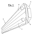
- the optical group which produces an adjustable light beam is assembled inside lighting appliances (such as emergency lamps) of the type indicated with 8 in figures 1 and 2 enclosed, and essentially comprises two linear fluorescent lamps, indicated with 10 and 11, a specular reflector 12 having a shaped body 5 and a containment structure or lamp-holder 9.
- the optical group has a symmetry with respect to the line S passing through the middle point M of the axis K joining the centres C1, C2 of the two fluorescent lamps 10, 11 and perpendicular to the same axis K.
- the lamps 10, 11 are situated in fixed positions, whereas the body 5 of the specular reflector 12 is equipped with two side flaps 6, which, as they can be opened and closed (varying their angular position), allow the variation of the light beam; furthermore, each flap 6 effects symmetrical side movements with respect to the respective symmetry axis S of each branch A1, A2 of the body 5 of the reflector 12, which has a profile which has been specifically studied and constructed so as to obtain an optics with ideal behaviour in all configurations of use.
- the body 5 of the reflector 12 consists of a central curvilinear surface consisting of two branches A1, A2, symmetrical with respect to the axis S of the optical group and, as already mentioned, in practice, the variation in the angular position of the flaps 6 allows light beams with different openings to be obtained.
- the position represented in figure 5, with the flaps 6 in a so-called closed position creates a narrow light beam (diagram of figure 5A), suitable therefore for installations at great heights or in the presence of narrow areas to be illuminated (corridors, warehouses with racks, etc.).
- Figure 4 schematically shows a functioning position with the flaps 6 in a partially open position (obtained by means of an approximate rotation of about 12 degrees from the closed position); in this case, the light beam produced is wider than the previous one (diagram of figure 4A) and guarantees excellent performances in installations.
- Figure 3 shows a functioning position with the flaps 6 in a completely open position (obtained by an approximate rotation of about 24 degrees from the closed position); in this case, an extremely wide light beam is obtained (diagram of figure 3A), almost identical to that obtained with a traditional lighting appliance, with the same emitted light power.
- the performances of the optical group are represented in both the diagrams of the light intensity distribution in the space of figures 3A, 4A, 5A, and also in the polar diagram of figure 6, where the diagrams of the illumination of an appliance of the traditional type are compared with those produced by the optical group according to the present invention, in the various functioning positions.
- a central body 15 is used, suitably shaped, so that, in correspondence with the opposite sides, 16, 17 and 18, 19 respectively, it has relative sides having the same shape as the angular positions of the flaps 6 shown in figures 3-5 and, in particular, the "open” or “partially open” and “closed” positions, respectively illustrated in figures 3, 4 and 5 and corresponding to a diffusing beam geometry (figures 3 and 4 and surfaces of the body 15 indicated with 16 and 19) and concentrating (figure 5 and surfaces of the body 15 indicated with 17 and 18).
- the central body 15 is suitably assembled to the body 5 of the reflector 12, for example according to a constructive solution by insertion, according to which the body 15 is kept in position, inside the central seat 25, positioned centrally with respect to the reflector 12, by means of the covering flaps 26, whose lower appendixes are engaged in the cavities 27 of the central seat 25.
- the fulcrum consisting of the central pin 20, connected to the body 15 and rotating inside the interstice defined by the walls 21, 22 (solution illustrated in figure 7), allows the rotation of the same body 15 around the longitudinal axis, according to the direction of the arrow F.
- the optical group according to the invention is particularly advantageous for its great uniformity and illumination area which is obtained and, in particular, for the fact that controlled photometric performances can be obtained.
- a lighting appliance which comprises an optical group according to the invention, can not only substitute current lighting appliances, in particular suitable for emergency lighting, under all conditions so far considered, but in addition, its use can be extended to applications which have so far been reserved for special appliances (such as for example, watertight ceiling light fixtures with concentrating optics).
Landscapes
- Engineering & Computer Science (AREA)
- General Engineering & Computer Science (AREA)
- Non-Portable Lighting Devices Or Systems Thereof (AREA)
- Fastening Of Light Sources Or Lamp Holders (AREA)
- Laser Surgery Devices (AREA)
- Mechanical Light Control Or Optical Switches (AREA)
- Eyeglasses (AREA)
- Fittings On The Vehicle Exterior For Carrying Loads, And Devices For Holding Or Mounting Articles (AREA)
- Electrochromic Elements, Electrophoresis, Or Variable Reflection Or Absorption Elements (AREA)
Abstract
Description
- The present invention generally relates to an optical group with an adjustable light beam.
- More specifically, the invention relates to a lighting appliance, equipped with an optical group designed so that it can easily and rapidly vary the form of the light emission of the lighting appliance, according to the various application requirements.
- Correct lighting must ensure, in the field of vision, sufficiently high luminances, which are rationally distributed to allow the perception of important areas, and also details, reducing to the minimum all forms of dazzling effects.
- In particular, emergency lamps must guarantee a light flow which is sufficiently intense and concentrated for allowing exits to be easily and rapidly identified, also and above all in cases of danger.
- Luminance is the ratio between the intensity of a light source in a certain direction, and its apparent surface seen from the same direction; its value depends on the illumination, the reflection characteristics of the surfaces and the lighting and observation directions.
- Illumination, relating to a point of a surface, is defined as the ratio between the light flow which effects an element of the surface around the point, and the area of the element itself; the illumination can be easily predicted and measured by means of a luxmeter or illuminometer, and can therefore be conveniently and easily used for facing technical problems, such as for example the design of a lighting appliance.
- The performances of a lamp, in particular an emergency lamp, are normally evaluated by establishing an illumination datum on a work or utilization plane, conventionally consisting of a horizontal surface at a certain distance from the floor.
- When the light reaches this work plane directly from the light source, it is defined as having direct lighting, whereas when, on the other hand, the light reaches the work plane after being reflected, even various times, from the walls and/or ceiling of the room, it is defined as having indirect lighting.
- Intermediate cases are obviously extremely frequent, in which the light flow arrives on the work plane in direct and indirect percentages which have intermediate values with respect to those indicated above.
- Lamps and/or appliances with direct lighting are widely used for the artificial lighting of buildings for civil and industrial use, both as a main light source and as an emergency or safety source.
- These lamps generally comprise a hollow body in which in which at least one fluorescent tube can be housed, connecting it to terminals which allow the electric charge; the body is closed by means of transparent protection screens, which can be disassembled to allow continuous access to the tube and terminals.
- Known emergency lamps currently have a light distribution on the work plane which is not particularly uniform and substantially non-homogeneous, also in relation to the relative position of an observer with respect to the lamp.
- Furthermore, the illumination is relatively concentrated and not very intense and it is therefore not possible in practice to obtain an acceptable compromise between the light flow intensity and concentration of the beam, important parameters when an emergency situation arises in civil and working environments and substitutive fluorescent lamps must be used for their lighting.
- Finally, it is impossible to obtain a functioning flexibility, in the sense that the use of a single lighting device does not allow light beams to be obtained with different openings, suitable for being adopted for different uses and/or applications.
- An objective of the present invention is therefore to eliminate the drawbacks reported, by providing an optical group with an adjustable light beam which allows the form of the light emission of a lighting appliance to be varied, in relation to the various application requirements, at the same time, guaranteeing illumination on the work plane which is both uniform and concentrated and also sufficiently intense.
- A further objective of the present invention is to indicate an optical group with a variable light beam which satisfies the safety regulations in force.
- Another objective of the invention is to provide an optical group with an adjustable light beam, which is relatively simple to construct, safe and reliable, using substantially known technologies and relative inexpensive components.
- These and other objectives, according to the present invention, are achieved by providing an optical group with an adjustable light beam, according to claim 1 enclosed; further technical characteristics are present in the subsequent claims.
- The invention advantageously defines a new optics for a lighting appliance, which offers the possibility of producing different light beams in relation to various regulations of an optical component.
- The optical performances remain the maximum, especially with respect to the extremely high efficiency, all regulation conditions.
- In particular, the light efficiency, only slightly lower than that obtained with traditional appliances, thanks to the greater versatility, is able to guarantee higher performances under all conditions of use (also for appliances so far reserved for special applications, such as watertight ceiling light fixtures with concentrating optics).
- Further objectives and advantages of an optical group with an adjustable light beam, according to the present invention, will appear more evident from the following illustrative and non-limiting description, referring to the enclosed schematic drawings, in which:
- figure 1 is a perspective view of a lighting appliance which englobes an optical group with an adjustable light beam, in a first operating position of the reflector, according to a first embodiment of the present invention;
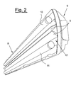
- figure 2 is a perspective view of the lighting appliance of figure 1, with the reflector of the optical group in a second operating position, according to the embodiment of figure 1 of the present invention;
- figure 3 shows an embodiment of the optical group with an adjustable light beam, with the reflector in a first functioning position, according to the embodiment of figures 1 and 2 of the present invention;
- figure 3A is a Cartesian diagram which shows the qualitative trend of the light intensity in the space produced by an optical group according to figure 3;
- figure 4 shows a scheme of the optical group with an adjustable light beam, with the reflector in a second functioning position, according to the embodiment of figures 1 and 2 of the present invention;
- figure 4A is a Cartesian diagram which shows the qualitative trend of the light intensity in the space produced by an optical group according to figure 4;
- figure 5 shows a scheme of the optical group with an adjustable light beam, with the reflector in a third functioning position, according to the embodiment of figures 1 and 2 of the present invention;
- figure 5A is a Cartesian diagram which shows the qualitative trend of the light intensity in the space produced by an optical group according to figure 5;
- figure 6 shows the qualitative trend of the illumination, in polar coordinates, produced by an optical group with an adjustable light beam, in the various functioning positions and compared with the illumination produced by an appliances of the traditional type, having the same emitted light power;
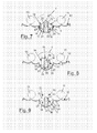
- figures 7, 8 and 9 refer to respective functioning positions of a further embodiment of the optical group with an adjustable light beam, according to the present invention.
- With particular reference to figures 1-6 mentioned above, the optical group which produces an adjustable light beam, according to the present invention, is assembled inside lighting appliances (such as emergency lamps) of the type indicated with 8 in figures 1 and 2 enclosed, and essentially comprises two linear fluorescent lamps, indicated with 10 and 11, a
specular reflector 12 having ashaped body 5 and a containment structure or lamp-holder 9. - As shown in figures 3-5 enclosed, in a section perpendicular to the axes of the
lamps fluorescent lamps - The
lamps body 5 of thespecular reflector 12 is equipped with twoside flaps 6, which, as they can be opened and closed (varying their angular position), allow the variation of the light beam; furthermore, eachflap 6 effects symmetrical side movements with respect to the respective symmetry axis S of each branch A1, A2 of thebody 5 of thereflector 12, which has a profile which has been specifically studied and constructed so as to obtain an optics with ideal behaviour in all configurations of use. - In particular, the
body 5 of thereflector 12 consists of a central curvilinear surface consisting of two branches A1, A2, symmetrical with respect to the axis S of the optical group and, as already mentioned, in practice, the variation in the angular position of theflaps 6 allows light beams with different openings to be obtained. - In particular, the position represented in figure 5, with the
flaps 6 in a so-called closed position, creates a narrow light beam (diagram of figure 5A), suitable therefore for installations at great heights or in the presence of narrow areas to be illuminated (corridors, warehouses with racks, etc.). - Figure 4 schematically shows a functioning position with the
flaps 6 in a partially open position (obtained by means of an approximate rotation of about 12 degrees from the closed position); in this case, the light beam produced is wider than the previous one (diagram of figure 4A) and guarantees excellent performances in installations. - Figure 3 shows a functioning position with the
flaps 6 in a completely open position (obtained by an approximate rotation of about 24 degrees from the closed position); in this case, an extremely wide light beam is obtained (diagram of figure 3A), almost identical to that obtained with a traditional lighting appliance, with the same emitted light power. - The performances of the optical group are represented in both the diagrams of the light intensity distribution in the space of figures 3A, 4A, 5A, and also in the polar diagram of figure 6, where the diagrams of the illumination of an appliance of the traditional type are compared with those produced by the optical group according to the present invention, in the various functioning positions.
- These functioning specifications are also satisfied by using a production variant with respect to what is represented in figures 1-6 and described above; in particular, with reference to figures 7-9 enclosed, a different mechanical solution is envisaged for varying the geometry of the central area of the
body 5 of thereflector 12. - More specifically, instead of envisaging the rotation of the
flaps 6 around two specular points with respect to the central axis S, as illustrated in figures 1-6 and described above, acentral body 15 is used, suitably shaped, so that, in correspondence with the opposite sides, 16, 17 and 18, 19 respectively, it has relative sides having the same shape as the angular positions of theflaps 6 shown in figures 3-5 and, in particular, the "open" or "partially open" and "closed" positions, respectively illustrated in figures 3, 4 and 5 and corresponding to a diffusing beam geometry (figures 3 and 4 and surfaces of thebody 15 indicated with 16 and 19) and concentrating (figure 5 and surfaces of thebody 15 indicated with 17 and 18). - The
central body 15 is suitably assembled to thebody 5 of thereflector 12, for example according to a constructive solution by insertion, according to which thebody 15 is kept in position, inside thecentral seat 25, positioned centrally with respect to thereflector 12, by means of the coveringflaps 26, whose lower appendixes are engaged in thecavities 27 of thecentral seat 25. - The fulcrum, consisting of the
central pin 20, connected to thebody 15 and rotating inside the interstice defined by thewalls 21, 22 (solution illustrated in figure 7), allows the rotation of thesame body 15 around the longitudinal axis, according to the direction of the arrow F. - By subsequently rotating the
body 15 along the direction F, it is possible to pass from a constructive solution with a concentrating light beam (figure 7, in which thesurfaces body 15, geometrically shaped so as to obtain a concentrating light beam, corresponding to the angular positioning of theflaps 6 of figure 5, are positioned above thebody 5 of the reflector 12), passing through an intermediate rotation position (figure 8), to a constructive solution with a diffusing light beam (figure 9, in which thesurfaces body 15, geometrically shaped so as to obtain a diffusing light beam, corresponding to the angular positioning of theflaps 6 of figure 3 or 4, according to the curvature imparted to theabove surfaces body 5 of the reflector 12). - The advantages of this constructive solution, with the same illuminotechnical results reached, mainly consist in the great simplicity for the final user of univocally varying the type of optics; all of this naturally derives from the simplicity of the mechanism adopted, which in turn guarantees an extreme reliability of the product.
- In short, by using both the constructive solution with flaps and also the constructive solution with a rotating central body, all the project specifications are satisfied and the light efficiency of the optical group, according to the invention, even if slightly lower than that of traditional lighting appliances, with the same emitted power, thanks to the wider versatility, is able to guarantee higher performances under all conditions of use; in particular the following advantages are obtained:
- an average illumination practically the same (+ 1%) as that of lighting appliances of the known type, with the same emitted power, on normal plants;
- a much higher illumination (+ 15-21%) than that obtained with traditional lighting appliances, with the same emitted power, on particular applications, in which an extremely concentrated light beam is required.
- In practice, it has been affirmed that the optical group according to the invention is particularly advantageous for its great uniformity and illumination area which is obtained and, in particular, for the fact that controlled photometric performances can be obtained.
- To conclude, a lighting appliance which comprises an optical group according to the invention, can not only substitute current lighting appliances, in particular suitable for emergency lighting, under all conditions so far considered, but in addition, its use can be extended to applications which have so far been reserved for special appliances (such as for example, watertight ceiling light fixtures with concentrating optics).
- The characteristics of the optical group with an adjustable light beam, object of the present invention, are evident from the above description, as also the advantages.
- Finally, numerous other variants can obviously be applied to the optical group in question, all included in the novelty principles inherent in the inventive idea. It is also evident that in the practical embodiment of the invention, the materials, forms and dimensions of the details illustrated can vary according to requirements and be substituted with other equivalent technical solutions.
Claims (8)
- An optical group with an adjustable light beam, of the type suitable for being assembled inside at least one lighting appliances (8), comprising at least one containment element or lamp-holder (9), which includes at least two light sources (10, 11) situated above a specular reflector (12), characterized in that in correspondence with the space present between said two light sources (10, 11), there are at least two curvilinear surfaces (6, 16, 17, 18, 19), which can be positioned according to variable and pre-established, in order to obtain light beams with different openings.
- The optical group according to claim 1, characterized in that said light sources (10, 11) comprise linear fluorescent lamps.
- The optical group according to claim 2, characterized in that said curvilinear surfaces (6) are situated on the body (5) of said specular reflector (12) and can move around two specular points with respect to a central axis (S), the central axis (S) being perpendicular to the axis (K) which connects the centres (C1, C2) of the fluorescent lamps.
- The optical group according to claim 1, characterized in that said light sources (10, 11) are situated in fixed positions.
- The optical group according to claim 1, characterized in that when the curvilinear surfaces (6, 16-19) are in a closed position and have at least one vertex (M) in common, a narrow light beam is created suitable for installations at great heights or in the presence of narrow areas to be illuminated.
- The optical group according to claim 5, characterized in that said curvilinear surfaces (6, 16, 17, 18, 19) can be in more or less open positions in correspondence with said vertex (M), so as to produce a wide and/or extremely wide light beam.
- The optical group according to claim 1, characterized in that said curvilinear surfaces (6, 16, 17, 18, 19) are situated on opposite sides of at least one shaped body (15), suitable for being assembled centrally with respect to said specular reflector (12).
- The optical group according to claim 7, characterized in that said shaped body (15) is assembled to the specular reflector (12) by means of an insertion system, which allows the rotation (F) of the shaped body (15) around a longitudinal axis.
Applications Claiming Priority (1)
| Application Number | Priority Date | Filing Date | Title |
|---|---|---|---|
| IT000297A ITVI20050297A1 (en) | 2005-11-11 | 2005-11-11 | ADJUSTABLE BRIGHT OPTICAL GROUP |
Publications (3)
| Publication Number | Publication Date |
|---|---|
| EP1785667A2 true EP1785667A2 (en) | 2007-05-16 |
| EP1785667A3 EP1785667A3 (en) | 2007-05-30 |
| EP1785667B1 EP1785667B1 (en) | 2009-09-30 |
Family
ID=37561326
Family Applications (1)
| Application Number | Title | Priority Date | Filing Date |
|---|---|---|---|
| EP06123798A Not-in-force EP1785667B1 (en) | 2005-11-11 | 2006-11-10 | Optical group with an adjustable light beam |
Country Status (4)
| Country | Link |
|---|---|
| EP (1) | EP1785667B1 (en) |
| AT (1) | ATE444466T1 (en) |
| DE (1) | DE602006009458D1 (en) |
| IT (1) | ITVI20050297A1 (en) |
Cited By (1)
| Publication number | Priority date | Publication date | Assignee | Title |
|---|---|---|---|---|
| CN101581440B (en) * | 2008-12-04 | 2011-03-30 | 余高辉 | High-brightness illuminating device |
Citations (3)
| Publication number | Priority date | Publication date | Assignee | Title |
|---|---|---|---|---|
| JPH07220513A (en) * | 1994-02-02 | 1995-08-18 | Ohbayashi Corp | Luminaire with variable reflecting plate |
| EP0959296A2 (en) * | 1998-05-20 | 1999-11-24 | Herbert Waldmann GmbH & Co. | Luminaire comprising an adjustable reflector |
| US20020105807A1 (en) * | 2001-02-05 | 2002-08-08 | Loughrey James F. | Variable focus indirect lighting fixture |
-
2005
- 2005-11-11 IT IT000297A patent/ITVI20050297A1/en unknown
-
2006
- 2006-11-10 DE DE602006009458T patent/DE602006009458D1/en active Active
- 2006-11-10 EP EP06123798A patent/EP1785667B1/en not_active Not-in-force
- 2006-11-10 AT AT06123798T patent/ATE444466T1/en not_active IP Right Cessation
Patent Citations (3)
| Publication number | Priority date | Publication date | Assignee | Title |
|---|---|---|---|---|
| JPH07220513A (en) * | 1994-02-02 | 1995-08-18 | Ohbayashi Corp | Luminaire with variable reflecting plate |
| EP0959296A2 (en) * | 1998-05-20 | 1999-11-24 | Herbert Waldmann GmbH & Co. | Luminaire comprising an adjustable reflector |
| US20020105807A1 (en) * | 2001-02-05 | 2002-08-08 | Loughrey James F. | Variable focus indirect lighting fixture |
Cited By (1)
| Publication number | Priority date | Publication date | Assignee | Title |
|---|---|---|---|---|
| CN101581440B (en) * | 2008-12-04 | 2011-03-30 | 余高辉 | High-brightness illuminating device |
Also Published As
| Publication number | Publication date |
|---|---|
| ATE444466T1 (en) | 2009-10-15 |
| DE602006009458D1 (en) | 2009-11-12 |
| ITVI20050297A1 (en) | 2007-05-12 |
| EP1785667B1 (en) | 2009-09-30 |
| EP1785667A3 (en) | 2007-05-30 |
Similar Documents
| Publication | Publication Date | Title |
|---|---|---|
| RU2562041C2 (en) | Light-emitting device and lighting fitting | |
| US9279550B2 (en) | Luminaires having batwing photometric distribution | |
| CN1661274B (en) | Surgical lamp | |
| JP6029031B2 (en) | Illumination system and luminaire providing the appearance of sunlight | |
| JP6250687B2 (en) | Lighting device and lighting system | |
| CN106461189A (en) | Lighting device having a lens with a profiled structure | |
| EP1248033B1 (en) | Reflector lamp, especially floor-, ceiling- or wall-reflector lamp of the recessed type | |
| EP1792119B1 (en) | Luminaire with louver members | |
| US20210116085A1 (en) | Luminaire | |
| WO2013182966A1 (en) | Lighting device with optical reflector, luminaire having such lighting device and method of manufacturing a compact optical reflector | |
| US8356914B2 (en) | Luminaires and optics for control and distribution of multiple quasi point source light sources such as LEDs | |
| EP1785667B1 (en) | Optical group with an adjustable light beam | |
| WO2015047078A1 (en) | Indirect illumination system | |
| US10054290B2 (en) | Movable barrier operator light distribution | |
| CN100507344C (en) | Method and apparatus for lighting with reflection | |
| WO2019203760A2 (en) | Lighting system based on sight blocking and multiple reflection for point and directional light sources | |
| US5289357A (en) | Task-oriented light fixture for a workspace | |
| KR200387728Y1 (en) | Reflecting shade for lighting equipment | |
| CN209540539U (en) | Lighting device | |
| EP2596282B1 (en) | Lighting module with optimized emission, in particular for road illumination | |
| KR200417263Y1 (en) | The louver of replection plate | |
| CN109869643A (en) | Lighting device | |
| EP3869243B1 (en) | Improved lighting device for a complete and precise projection of a light beam and a method of its use | |
| DE202005018710U1 (en) | Illuminating device for object, has reflection unit moved from one position, in which unit reflects light coming from source, to another position, in which unit stands in unnoticeable interaction with light originating from source | |
| CA2910093C (en) | Movable barrier operator light distribution |
Legal Events
| Date | Code | Title | Description |
|---|---|---|---|
| PUAI | Public reference made under article 153(3) epc to a published international application that has entered the european phase |
Free format text: ORIGINAL CODE: 0009012 |
|
| PUAL | Search report despatched |
Free format text: ORIGINAL CODE: 0009013 |
|
| AK | Designated contracting states |
Kind code of ref document: A2 Designated state(s): AT BE BG CH CY CZ DE DK EE ES FI FR GB GR HU IE IS IT LI LT LU LV MC NL PL PT RO SE SI SK TR |
|
| AX | Request for extension of the european patent |
Extension state: AL BA HR MK YU |
|
| AK | Designated contracting states |
Kind code of ref document: A3 Designated state(s): AT BE BG CH CY CZ DE DK EE ES FI FR GB GR HU IE IS IT LI LT LU LV MC NL PL PT RO SE SI SK TR |
|
| AX | Request for extension of the european patent |
Extension state: AL BA HR MK YU |
|
| 17P | Request for examination filed |
Effective date: 20071026 |
|
| 17Q | First examination report despatched |
Effective date: 20071213 |
|
| AKX | Designation fees paid |
Designated state(s): AT BE BG CH CY CZ DE DK EE ES FI FR GB GR HU IE IS IT LI LT LU LV MC NL PL PT RO SE SI SK TR |
|
| GRAP | Despatch of communication of intention to grant a patent |
Free format text: ORIGINAL CODE: EPIDOSNIGR1 |
|
| GRAS | Grant fee paid |
Free format text: ORIGINAL CODE: EPIDOSNIGR3 |
|
| GRAA | (expected) grant |
Free format text: ORIGINAL CODE: 0009210 |
|
| AK | Designated contracting states |
Kind code of ref document: B1 Designated state(s): AT BE BG CH CY CZ DE DK EE ES FI FR GB GR HU IE IS IT LI LT LU LV MC NL PL PT RO SE SI SK TR |
|
| REG | Reference to a national code |
Ref country code: CH Ref legal event code: EP Ref country code: GB Ref legal event code: FG4D |
|
| REG | Reference to a national code |
Ref country code: IE Ref legal event code: FG4D |
|
| REF | Corresponds to: |
Ref document number: 602006009458 Country of ref document: DE Date of ref document: 20091112 Kind code of ref document: P |
|
| PG25 | Lapsed in a contracting state [announced via postgrant information from national office to epo] |
Ref country code: FI Free format text: LAPSE BECAUSE OF FAILURE TO SUBMIT A TRANSLATION OF THE DESCRIPTION OR TO PAY THE FEE WITHIN THE PRESCRIBED TIME-LIMIT Effective date: 20090930 Ref country code: SE Free format text: LAPSE BECAUSE OF FAILURE TO SUBMIT A TRANSLATION OF THE DESCRIPTION OR TO PAY THE FEE WITHIN THE PRESCRIBED TIME-LIMIT Effective date: 20090930 Ref country code: LT Free format text: LAPSE BECAUSE OF FAILURE TO SUBMIT A TRANSLATION OF THE DESCRIPTION OR TO PAY THE FEE WITHIN THE PRESCRIBED TIME-LIMIT Effective date: 20090930 |
|
| LTIE | Lt: invalidation of european patent or patent extension |
Effective date: 20090930 |
|
| PG25 | Lapsed in a contracting state [announced via postgrant information from national office to epo] |
Ref country code: SI Free format text: LAPSE BECAUSE OF FAILURE TO SUBMIT A TRANSLATION OF THE DESCRIPTION OR TO PAY THE FEE WITHIN THE PRESCRIBED TIME-LIMIT Effective date: 20090930 Ref country code: PL Free format text: LAPSE BECAUSE OF FAILURE TO SUBMIT A TRANSLATION OF THE DESCRIPTION OR TO PAY THE FEE WITHIN THE PRESCRIBED TIME-LIMIT Effective date: 20090930 Ref country code: LV Free format text: LAPSE BECAUSE OF FAILURE TO SUBMIT A TRANSLATION OF THE DESCRIPTION OR TO PAY THE FEE WITHIN THE PRESCRIBED TIME-LIMIT Effective date: 20090930 |
|
| NLV1 | Nl: lapsed or annulled due to failure to fulfill the requirements of art. 29p and 29m of the patents act | ||
| PG25 | Lapsed in a contracting state [announced via postgrant information from national office to epo] |
Ref country code: IS Free format text: LAPSE BECAUSE OF FAILURE TO SUBMIT A TRANSLATION OF THE DESCRIPTION OR TO PAY THE FEE WITHIN THE PRESCRIBED TIME-LIMIT Effective date: 20100130 Ref country code: EE Free format text: LAPSE BECAUSE OF FAILURE TO SUBMIT A TRANSLATION OF THE DESCRIPTION OR TO PAY THE FEE WITHIN THE PRESCRIBED TIME-LIMIT Effective date: 20090930 Ref country code: RO Free format text: LAPSE BECAUSE OF FAILURE TO SUBMIT A TRANSLATION OF THE DESCRIPTION OR TO PAY THE FEE WITHIN THE PRESCRIBED TIME-LIMIT Effective date: 20090930 Ref country code: PT Free format text: LAPSE BECAUSE OF FAILURE TO SUBMIT A TRANSLATION OF THE DESCRIPTION OR TO PAY THE FEE WITHIN THE PRESCRIBED TIME-LIMIT Effective date: 20100201 Ref country code: ES Free format text: LAPSE BECAUSE OF FAILURE TO SUBMIT A TRANSLATION OF THE DESCRIPTION OR TO PAY THE FEE WITHIN THE PRESCRIBED TIME-LIMIT Effective date: 20100110 |
|
| PG25 | Lapsed in a contracting state [announced via postgrant information from national office to epo] |
Ref country code: SK Free format text: LAPSE BECAUSE OF FAILURE TO SUBMIT A TRANSLATION OF THE DESCRIPTION OR TO PAY THE FEE WITHIN THE PRESCRIBED TIME-LIMIT Effective date: 20090930 |
|
| PG25 | Lapsed in a contracting state [announced via postgrant information from national office to epo] |
Ref country code: BE Free format text: LAPSE BECAUSE OF FAILURE TO SUBMIT A TRANSLATION OF THE DESCRIPTION OR TO PAY THE FEE WITHIN THE PRESCRIBED TIME-LIMIT Effective date: 20090930 Ref country code: MC Free format text: LAPSE BECAUSE OF NON-PAYMENT OF DUE FEES Effective date: 20091130 Ref country code: AT Free format text: LAPSE BECAUSE OF FAILURE TO SUBMIT A TRANSLATION OF THE DESCRIPTION OR TO PAY THE FEE WITHIN THE PRESCRIBED TIME-LIMIT Effective date: 20090930 |
|
| PG25 | Lapsed in a contracting state [announced via postgrant information from national office to epo] |
Ref country code: NL Free format text: LAPSE BECAUSE OF FAILURE TO SUBMIT A TRANSLATION OF THE DESCRIPTION OR TO PAY THE FEE WITHIN THE PRESCRIBED TIME-LIMIT Effective date: 20090930 Ref country code: DK Free format text: LAPSE BECAUSE OF FAILURE TO SUBMIT A TRANSLATION OF THE DESCRIPTION OR TO PAY THE FEE WITHIN THE PRESCRIBED TIME-LIMIT Effective date: 20090930 |
|
| PLBE | No opposition filed within time limit |
Free format text: ORIGINAL CODE: 0009261 |
|
| STAA | Information on the status of an ep patent application or granted ep patent |
Free format text: STATUS: NO OPPOSITION FILED WITHIN TIME LIMIT |
|
| 26N | No opposition filed |
Effective date: 20100701 |
|
| PG25 | Lapsed in a contracting state [announced via postgrant information from national office to epo] |
Ref country code: GR Free format text: LAPSE BECAUSE OF FAILURE TO SUBMIT A TRANSLATION OF THE DESCRIPTION OR TO PAY THE FEE WITHIN THE PRESCRIBED TIME-LIMIT Effective date: 20091231 Ref country code: IE Free format text: LAPSE BECAUSE OF NON-PAYMENT OF DUE FEES Effective date: 20091110 |
|
| PGFP | Annual fee paid to national office [announced via postgrant information from national office to epo] |
Ref country code: FR Payment date: 20101123 Year of fee payment: 5 |
|
| PGFP | Annual fee paid to national office [announced via postgrant information from national office to epo] |
Ref country code: CZ Payment date: 20101013 Year of fee payment: 5 |
|
| PG25 | Lapsed in a contracting state [announced via postgrant information from national office to epo] |
Ref country code: BG Free format text: LAPSE BECAUSE OF FAILURE TO SUBMIT A TRANSLATION OF THE DESCRIPTION OR TO PAY THE FEE WITHIN THE PRESCRIBED TIME-LIMIT Effective date: 20091130 |
|
| PGFP | Annual fee paid to national office [announced via postgrant information from national office to epo] |
Ref country code: GB Payment date: 20101110 Year of fee payment: 5 Ref country code: IT Payment date: 20101110 Year of fee payment: 5 |
|
| PG25 | Lapsed in a contracting state [announced via postgrant information from national office to epo] |
Ref country code: LU Free format text: LAPSE BECAUSE OF NON-PAYMENT OF DUE FEES Effective date: 20091110 |
|
| PGFP | Annual fee paid to national office [announced via postgrant information from national office to epo] |
Ref country code: DE Payment date: 20110124 Year of fee payment: 5 |
|
| PG25 | Lapsed in a contracting state [announced via postgrant information from national office to epo] |
Ref country code: HU Free format text: LAPSE BECAUSE OF FAILURE TO SUBMIT A TRANSLATION OF THE DESCRIPTION OR TO PAY THE FEE WITHIN THE PRESCRIBED TIME-LIMIT Effective date: 20100401 |
|
| REG | Reference to a national code |
Ref country code: CH Ref legal event code: PL |
|
| PG25 | Lapsed in a contracting state [announced via postgrant information from national office to epo] |
Ref country code: LI Free format text: LAPSE BECAUSE OF NON-PAYMENT OF DUE FEES Effective date: 20101130 Ref country code: CH Free format text: LAPSE BECAUSE OF NON-PAYMENT OF DUE FEES Effective date: 20101130 |
|
| PG25 | Lapsed in a contracting state [announced via postgrant information from national office to epo] |
Ref country code: TR Free format text: LAPSE BECAUSE OF FAILURE TO SUBMIT A TRANSLATION OF THE DESCRIPTION OR TO PAY THE FEE WITHIN THE PRESCRIBED TIME-LIMIT Effective date: 20090930 |
|
| PG25 | Lapsed in a contracting state [announced via postgrant information from national office to epo] |
Ref country code: CY Free format text: LAPSE BECAUSE OF FAILURE TO SUBMIT A TRANSLATION OF THE DESCRIPTION OR TO PAY THE FEE WITHIN THE PRESCRIBED TIME-LIMIT Effective date: 20090930 |
|
| GBPC | Gb: european patent ceased through non-payment of renewal fee |
Effective date: 20111110 |
|
| PG25 | Lapsed in a contracting state [announced via postgrant information from national office to epo] |
Ref country code: CZ Free format text: LAPSE BECAUSE OF NON-PAYMENT OF DUE FEES Effective date: 20111110 |
|
| REG | Reference to a national code |
Ref country code: FR Ref legal event code: ST Effective date: 20120731 |
|
| PG25 | Lapsed in a contracting state [announced via postgrant information from national office to epo] |
Ref country code: IT Free format text: LAPSE BECAUSE OF NON-PAYMENT OF DUE FEES Effective date: 20111110 |
|
| REG | Reference to a national code |
Ref country code: DE Ref legal event code: R119 Ref document number: 602006009458 Country of ref document: DE Effective date: 20120601 |
|
| PG25 | Lapsed in a contracting state [announced via postgrant information from national office to epo] |
Ref country code: GB Free format text: LAPSE BECAUSE OF NON-PAYMENT OF DUE FEES Effective date: 20111110 |
|
| PG25 | Lapsed in a contracting state [announced via postgrant information from national office to epo] |
Ref country code: FR Free format text: LAPSE BECAUSE OF NON-PAYMENT OF DUE FEES Effective date: 20111130 |
|
| PG25 | Lapsed in a contracting state [announced via postgrant information from national office to epo] |
Ref country code: DE Free format text: LAPSE BECAUSE OF NON-PAYMENT OF DUE FEES Effective date: 20120601 |