EP1785663A1 - Dispositif de sécurité de contact - Google Patents
Dispositif de sécurité de contact Download PDFInfo
- Publication number
- EP1785663A1 EP1785663A1 EP06291752A EP06291752A EP1785663A1 EP 1785663 A1 EP1785663 A1 EP 1785663A1 EP 06291752 A EP06291752 A EP 06291752A EP 06291752 A EP06291752 A EP 06291752A EP 1785663 A1 EP1785663 A1 EP 1785663A1
- Authority
- EP
- European Patent Office
- Prior art keywords
- probe
- actuated
- contact
- safety device
- lever
- Prior art date
- Legal status (The legal status is an assumption and is not a legal conclusion. Google has not performed a legal analysis and makes no representation as to the accuracy of the status listed.)
- Granted
Links
- 239000000523 sample Substances 0.000 claims abstract description 31
- 230000005540 biological transmission Effects 0.000 claims abstract description 30
- 230000033001 locomotion Effects 0.000 claims abstract description 10
- 238000006073 displacement reaction Methods 0.000 claims abstract description 8
- 230000000977 initiatory effect Effects 0.000 claims abstract description 4
- 230000007246 mechanism Effects 0.000 abstract description 9
- 230000000903 blocking effect Effects 0.000 abstract description 7
- 241000282461 Canis lupus Species 0.000 description 5
- 240000009088 Fragaria x ananassa Species 0.000 description 1
- 241000282414 Homo sapiens Species 0.000 description 1
- 230000003321 amplification Effects 0.000 description 1
- 229920001971 elastomer Polymers 0.000 description 1
- 239000000806 elastomer Substances 0.000 description 1
- 238000010304 firing Methods 0.000 description 1
- 230000010354 integration Effects 0.000 description 1
- 238000012423 maintenance Methods 0.000 description 1
- 230000007257 malfunction Effects 0.000 description 1
- 238000003199 nucleic acid amplification method Methods 0.000 description 1
- 235000021012 strawberries Nutrition 0.000 description 1
- 230000001131 transforming effect Effects 0.000 description 1
Images


Classifications
-
- F—MECHANICAL ENGINEERING; LIGHTING; HEATING; WEAPONS; BLASTING
- F16—ENGINEERING ELEMENTS AND UNITS; GENERAL MEASURES FOR PRODUCING AND MAINTAINING EFFECTIVE FUNCTIONING OF MACHINES OR INSTALLATIONS; THERMAL INSULATION IN GENERAL
- F16P—SAFETY DEVICES IN GENERAL; SAFETY DEVICES FOR PRESSES
- F16P5/00—Emergency means for rendering ineffective a coupling conveying reciprocating movement if the motion of the driven part is prematurely resisted
-
- F—MECHANICAL ENGINEERING; LIGHTING; HEATING; WEAPONS; BLASTING
- F41—WEAPONS
- F41A—FUNCTIONAL FEATURES OR DETAILS COMMON TO BOTH SMALLARMS AND ORDNANCE, e.g. CANNONS; MOUNTINGS FOR SMALLARMS OR ORDNANCE
- F41A21/00—Barrels; Gun tubes; Muzzle attachments; Barrel mounting means
- F41A21/48—Barrel mounting means, e.g. releasable mountings for replaceable barrels
-
- F—MECHANICAL ENGINEERING; LIGHTING; HEATING; WEAPONS; BLASTING
- F41—WEAPONS
- F41A—FUNCTIONAL FEATURES OR DETAILS COMMON TO BOTH SMALLARMS AND ORDNANCE, e.g. CANNONS; MOUNTINGS FOR SMALLARMS OR ORDNANCE
- F41A31/00—Testing arrangements
- F41A31/02—Testing arrangements for checking gun barrels
Definitions
- the technical sector of the present invention is that of safety devices for controlling the connection of two mechanical parts.
- the object of the present invention is to provide a contact security device between two moving parts to ensure their perfect connection and prohibit a transmission of motion when this contact is not made.
- the subject of the invention is therefore a device for the safety of contact between two moving mechanical parts with respect to each other in order to guarantee the internal kinematics by release or initiation of a control means, characterized in that it comprises a security box connected to one of said parts enclosing a probe actuated by the moving part and an amplifying means consisting of an amplifying lever actuated by the probe and a locking latch; blocking actuated by the amplifying lever engages the control means to transform a rectilinear micro-displacement into a large circular motion.
- the device according to the invention can be coupled to a manual control acting on the probe can also ensure the locking of the transmission shaft in a fraction of a turn and find in first application the rapid immobilization of cutting tools of the type grinding wheels, blades, cut-off line, forests, strawberries, ...
- the probe is actuated in translation and the lever and the latch are actuated in rotation.
- control means is represented by a hydraulic or pneumatic distributor, or an electric switch.
- control means is represented by a transmission shaft, the two mechanical parts being constituted by a gun tube and a bolt sleeve.
- the security box is fixed on the yoke sleeve in the vicinity of the transmission shaft.
- the locking lock is engaged on a cam carried by the transmission shaft.
- the safety box is in the form of a one-piece piece provided with a first bore in which the feeler slides and a second bore in which are inserted the amplifying lever and the lock, the two bores being arranged in substantially perpendicular directions.
- the amplifying lever and the latch are in contact with one another at a cam to ensure their rotation each around an axis fixed on the security housing.
- the probe and the lock are subjected to the action of a return means.
- the locking bolt bears on an adjustable stop.
- the amplifying lever pivots about an axis adjustable by the eccentric.
- a first advantage of the device according to the invention lies in the guarantee of the operating prohibition of the dangerous mechanism for an operator if the two parts are properly assembled.
- Another advantage lies in the possibility of the complete blocking of the control means if the moving part is not brought into its nominal operating position.
- Another advantage lies in the fact that the lock ensures the locking in rotation of the transmission shaft as the rotation of the lock is not complete.
- the safety device ensures the contact between two mechanical parts by blocking or not a transmission shaft.
- the device according to the invention can be implemented so as to control any mechanical part, to actuate an electrical switch, to cause the electrical contact between two parts, and more generally to generate a command to to authorize or to prohibit the transmission of an order.
- the control means can therefore be represented by a hydraulic or pneumatic distributor, or an electric switch.
- Figure 1 which is a perspective view of a partially represented gun tube 1 and a breech sleeve 2 coming into contact with each other during firing sessions. It is understood that a perfect contact between these two parts must be ensured in order to avoid leakage of gas causing danger for an operator located nearby. When the contact between these two parts is not perfect, the following sequence must be interrupted by the blocking of a transmission shaft 3 fixed on the sleeve.
- the contact safety device comprises a security box 4 connected here to the sleeve by a suitable attachment, screws 5 for example.
- This housing 4 encloses a probe 6 actuated in translation by the tube 1 and an amplifier means consisting of an amplifying lever 7 (not visible in this figure) actuated by the probe 6 and a locking latch 8 actuated by the amplifier lever in engagement with the transmission shaft 3 carrying a ratchet wheel 9.
- This structure is provided to guarantee the internal kinematics by release or initiation of the control means by transforming a rectilinear micro-displacement of the probe 6 into a large-scale circular motion as will be explained below.
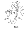
- the perspective view shown in Figure 2 shows the security housing 4 is in the form of a machined part provided with wings 10 and 11 for attachment to the sleeve 2 with screws.
- the housing 4 further comprises a clevis 12 for receiving the transmission shaft 3.
- the housing 4 comprises a first bore 13 in which is inserted the sensor 6 for displacement in translation, bore made in accordance with the configuration of the probe. This bore 13 is made in the direction of movement of the moving part 1.
- a second bore 14 is provided in the housing 4 in which the amplifier lever 7 and the latch 8 are inserted.
- the latch 8 is fixed by means of the transverse axis 15 around which it can pivot and the position of this lever is adjustable using a stop 16 screwed into the housing 4.
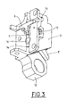
- FIG. 3 shows the same elements as in FIG. 2. This FIG. 3 shows the attachment of the amplifying lever 7 by means of the axis 17 and it can be seen that the lower end of the lock 8 is in protruding near the clevis 12.
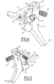
- FIGS. 4 and 5 illustrate the spatial arrangement of the probe 6, the amplifying lever 7 and the latch 8.
- the probe is subjected to the action of a return spring 18 placed between a probe wing and the safety box 4.
- This spring guarantees, in the absence of external force on the probe, the maintenance of the permanent contact of the probe with the safety box.
- the lock 8 is subjected to the action of a return spring 19 bearing on the housing 4 to ensure the permanent contact between the latch and the lever and able to constantly bring the latch against the stop 16.
- the probe 6 and the lever 7 are in mutual contact along a bearing surface 20 so that the translation of the probe 6 generates a rotation of the lever 7 about the axis 17.
- the lever 7 and the latch 8 are also in contact mutually along a bearing surface 21 so that the rotation of the lever causes the rotation of the lock about the axis 15 against the action of the spring 19.
- FIG. 5 the respective movements of the various parts of the casing 4 are illustrated.
- the probe 6 When the probe 6 is actuated in translation along the arrow F1 under the action of the moving part, it causes the lever 7 to rotate according to the arrow F2. . This rotation is accompanied by a pressure of the lever 7 on the latch 8 which is then rotated along the arrow F3. It has been calculated that the translation of the probe causes the lock to move at least 20 times relative to the stroke of this probe.
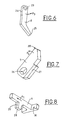
- FIG. 6 shows the latch 8 in the form of an open L whose one branch is provided with an opening 23 receiving the axis 15 and a surface 24 and whose other branch is terminated. by a wolf tooth 25 intended to cooperate with the transmission shaft.
- the lock may also incorporate a support instead of or in addition to the wolf's tooth.
- This support is intended to control either a hydraulic or pneumatic distributor, or an electrical switch.
- FIG. 7 shows the amplifying lever 7 provided with an aperture 26 for receiving the spindle 17 and an inclined surface 27.
- the spindle 17 carries an eccentric that makes it possible to modify, in the security box, the position of the opening 26 of the amplifier lever. This displacement thus makes it possible to modify the rotational stroke of the lever and therefore the amplification ratio of the movement of the lock.
- the amplifier lever 7 pivots on an adjustable axis thanks to the eccentric integrated on the axis 17.
- FIG. 8 shows the feeler 6 in the form of a T whose leg is provided with a finger 28 provided with a surface 29.
- the bar of the T has a bearing surface 30 of its spring 19.
- the housing 4 constitutes with the probe, the lever and the lock a one-piece assembly of high stiffness capable of dissipating in the lock the kinetic energy stored in the transmission shaft 3 during its immobilization.
- the lock represented monobloc therefore high stiffness, can be replaced by a set of three components: the lock, the energy dissipating spring (optionally in the form of elastomer) and the body of the lock. This subassembly, allowing effortless translation of the latch in the body of the latch, allows to dissipate the energy supplied by the transmission shaft during its blocking.
- FIGS. 9 and 10 there is shown the transmission shaft 3 provided with the ratchet wheel 9 defining cams 31 on which the latch 8 abuts thus blocking any rotation of the transmission shaft 3. Thanks to the translation of the probe 6 and successive rotations of the lever 7 and the latch 8, the wolf of the lock tooth is retracted relative to a cam releasing the transmission shaft 3. Thus, as long as the rotation of the lock 8 is not complete rotation of the shaft 3 is blocked and no motion transmission is ensured thus making the operation of the device reliable and free of malfunctions.
- the manual control is called dead man safety release because it corresponds to the additional mechanism imposing a constant manual support (push button for example) and whose stop action causes the return to the rest position of the push button and the translation of the probe under the action of its jurisdiction. Locking the rotation of the transmission shaft by the lock is thus guaranteed as soon as the manual action on the push button ceases.
Landscapes
- Engineering & Computer Science (AREA)
- General Engineering & Computer Science (AREA)
- Mechanical Engineering (AREA)
- Portable Nailing Machines And Staplers (AREA)
- Contacts (AREA)
- Length Measuring Devices With Unspecified Measuring Means (AREA)
- Push-Button Switches (AREA)
- Air Bags (AREA)
- Yarns And Mechanical Finishing Of Yarns Or Ropes (AREA)
Abstract
Description
- Le secteur technique de la présente invention est celui des dispositifs de sécurité permettant de contrôler la liaison de deux pièces mécaniques.
- La prise en compte des exigences de sécurité dans les mécanismes présentant un danger immédiat pour les opérateurs impose d'intégrer un composant indépendant du fonctionnement du mécanisme pour annihiler la poursuite de son action. C'est par exemple le cas de la liaison de deux pièces mécaniques à un instant (t) dont l'une est motrice et l'autre entraînée. La poursuite de l'action motrice de l'une des pièces mécaniques peut s'avérer très dangereuse pour un opérateur affecté à la conduite du mécanisme. Ainsi, dans le cas d'une arme dans laquelle le tube vient en contact avec le manchon de culasse, on doit s'assurer de la parfaite jonction de ces deux pièces afin que l'arbre de transmission soit parfaitement verrouillé en rotation. Ce type de problème se retrouve dans les commandes d'arrêt des générateurs d'énergie hydraulique, pneumatique, électrique ou mécanique si les deux pièces restent éloigner l'une de l'autre de quelques dixièmes de millimètres, présentant un danger pour les utilisateurs ou l'environnement. Il convient donc de concevoir un dispositif de sécurité garantissant le verrouillage mécanique en rotation de l'arbre de transmission si le tube n'est pas en position sur le manchon c'est-à-dire s'il subsiste un écart même très faible entre eux.
- Le but de la présente invention est de fournir un dispositif de sécurité de contact entre deux pièces en mouvement pour garantir leur parfaite liaison et interdire une transmission de mouvement lorsque ce contact n'est pas réalisé.
- L'invention a donc pour objet un dispositif de sécurité de contact entre deux pièces mécaniques mobiles l'une par rapport à l'autre pour garantir la cinématique interne par libération ou initiation d'un moyen de commande, caractérisé en ce qu'il comporte un boîtier de sécurité relié à l'une desdites pièces renfermant un palpeur actionné par la pièce mobile et un moyen amplificateur constitué d'un levier amplificateur actionné par le palpeur et d'un verrou de blocage actionné par le levier amplificateur en prise sur le moyen de commande afin de transformer un micro-déplacement rectiligne en un mouvement circulaire de grande ampleur.
- On comprend que le dispositif selon l'invention peut être couplé à une commande manuelle agissant sur le palpeur peut également assurer le blocage de l'arbre de transmission en une fraction de tour et trouver en première application l'immobilisation rapide des outils coupants du type meules, lames, chaîne de tronçonnage, forêts, fraises, ...
- Selon une autre caractéristique de l'invention, le palpeur est actionné en translation et le levier et le verrou sont actionnés en rotation.
- Selon encore une autre caractéristique de l'invention, le moyen de commande est représenté par un distributeur hydraulique ou pneumatique, ou un interrupteur électrique.
- Selon encore une autre caractéristique de l'invention, le moyen de commande est représenté par un arbre de transmission, les deux pièces mécaniques étant constituées par un tube d'arme et un manchon de culasse.
- Selon une autre caractéristique de l'invention, le boîtier de sécurité est fixé sur le manchon de culasse au voisinage de l'arbre de transmission.
- Avantageusement, le verrou de blocage est en prise sur une came portée par l'arbre de transmission.
- Selon encore une caractéristique, le boîtier de sécurité se présente sous la forme d'une pièce monobloc munie d'un premier alésage dans lequel coulisse le palpeur et un deuxième alésage dans lequel sont insérés le levier amplificateur et le verrou, les deux alésages étant disposés selon des directions sensiblement perpendiculaires.
- Avantageusement, le levier amplificateur et le verrou sont en contact l'un de l'autre au niveau d'une came pour assurer leur rotation chacun autour d'un axe fixé sur le boîtier de sécurité.
- Avantageusement encore, le palpeur et le verrou sont soumis à l'action d'un moyen de rappel.
- Avantageusement encore, le verrou de blocage est en appui sur une butée réglable.
- Avantageusement encore, le levier amplificateur pivote autour d'un axe réglable par l'excentrique.
- Un tout premier avantage du dispositif selon l'invention réside dans la garantie de l'interdiction de fonctionnement du mécanisme dangereux pour un opérateur si les deux pièces ne sont correctement assemblées.
- Un autre avantage réside dans la possibilité du blocage complet du moyen de commande si la pièce mobile n'est pas amenée dans sa position nominale de fonctionnement.
- Un autre avantage réside dans le fait que le verrou assure le blocage en rotation de l'arbre de transmission tant que la rotation du verrou n'est pas complète.
- D'autres caractéristiques, détails et avantages de l'invention ressortiront plus clairement de la description donnée ci-après à titre indicatif en relation avec des dessins dans lesquels :
- la figure 1 représente une vue de deux pièces mécaniques destinées à être assemblées,
- les figures 2 et 3 représentent une vue du boîtier de sécurité avec son mécanisme,
- les figures 4 et 5 représentent des vues perspectives montrant le mécanisme de sécurité en position assemblée,
- la figure 6 représente le verrou de blocage,
- la figure 7 représente le levier amplificateur,
- la figure 8 représente le palpeur,
- la figure 9 représente une vue de l'arbre de transmission, et
- la figure 10 est une coupe montrant la roue à rochet portée par l'arbre de transmission.
- Dans la description qui suit, on va décrire une application particulière de l'invention dans laquelle le dispositif de sécurité garantit le contact entre deux pièces mécaniques par le blocage ou non d'un arbre de transmission. Il va de soi que le dispositif selon l'invention peut être mis en oeuvre de façon à commander n'importe quelle pièce mécanique, à actionner un interrupteur électrique, à provoquer le contact électrique entre deux pièces, et plus généralement à engendrer une commande afin d'autoriser ou d'interdire la transmission d'un ordre. Le moyen de commande peut donc être représenté par un distributeur hydraulique ou pneumatique, ou un interrupteur électrique.
- Sur la figure 1 qui est une vue perspective d'un tube 1 d'arme partiellement représenté et d'un manchon de culasse 2 venant en contact l'un de l'autre au cours des séances de tir. On comprend qu'un contact parfait entre ces deux pièces doit être assuré afin d'éviter toute fuite de gaz entraînant un danger pour un opérateur situé à proximité. Lorsque le contact entre ces deux pièces n'est pas parfait, la séquence suivante doit être interrompue par le blocage d'un arbre de transmission 3 fixé sur le manchon. A cette fin, le dispositif de sécurité de contact comporte un boîtier de sécurité 4 relié ici au manchon par une fixation appropriée, des vis 5 par exemple. Ce boîtier 4 renferme un palpeur 6 actionné en translation par le tube 1 et un moyen amplificateur constitué d'un levier amplificateur 7 (non visible sur cette figure) actionné par le palpeur 6 et d'un verrou de blocage 8 actionné par le levier amplificateur en prise sur l'arbre de transmission 3 portant une roue à rochet 9. Cette structure est prévue pour garantir la cinématique interne par libération ou initiation du moyen de commande en transformant un micro-déplacement rectiligne du palpeur 6 en un mouvement circulaire de grande ampleur comme cela va être expliqué ci-après.
- La vue en perspective représentée sur la figure 2 montre le boîtier de sécurité 4 se présentant sous la forme d'une pièce usinée munie d'ailes 10 et 11 de fixation sur le manchon 2 à l'aide de vis. Le boîtier 4 comporte de plus une chape 12 de réception de l'arbre de transmission 3.
- Le boîtier 4 comporte un premier alésage 13 dans lequel est inséré le palpeur 6 pour des déplacements en translation, alésage réalisé en concordance avec la configuration du palpeur. Cet alésage 13 est pratiqué suivant la direction de déplacement de la pièce mobile 1. Un deuxième alésage 14 est prévu dans le boîtier 4 dans lequel le levier amplificateur 7 et le verrou 8 sont insérés. Le verrou 8 est fixé au moyen de l'axe transversal 15 autour duquel il peut pivoter et la position de ce levier est réglable à l'aide d'une butée 16 vissée dans le boîtier 4.
- On notera sur la figure que les deux alésages 13 et 14 sont disposés selon des directions perpendiculaires.
- Sur la figure 3, on retrouve les mêmes éléments que sur la figure 2. Cette figure 3 montre la fixation du levier amplificateur 7 à l'aide de l'axe 17 et l'on voit que l'extrémité inférieure du verrou 8 est en saillie au voisinage de la chape 12.
- Les figures 4 et 5 permettent d'illustrer la disposition spatiale du palpeur 6, du levier amplificateur 7 et du verrou 8. On voit que le palpeur est soumis à l'action d'un ressort 18 de rappel disposé entre une aile du palpeur et le boîtier de sécurité 4. Ce ressort garantit en l'absence d'effort externe sur le palpeur, le maintien du contact permanent du palpeur avec le boîtier de sécurité. De même, le verrou 8 est soumis à l'action d'un ressort de rappel 19 prenant appui sur le boîtier 4 pour garantir le contact permanent entre ce verrou et le levier et apte à ramener constamment le verrou contre la butée 16. Le palpeur 6 et le levier 7 sont en contact mutuel le long d'une surface d'appui 20 afin que la translation du palpeur 6 engendre une rotation du levier 7 autour de l'axe 17. Le levier 7 et le verrou 8 sont également en contact mutuel le long d'une surface d'appui 21 afin que la rotation du levier provoque la rotation du verrou autour de l'axe 15 contre l'action du ressort 19.
- Sur la figure 5, on a illustré les mouvements respectifs des différentes pièces du boîtier 4. Lorsque le palpeur 6 est actionné en translation selon la flèche F1 sous l'action de la pièce mobile, il provoque la rotation du levier 7 selon la flèche F2. Cette rotation s'accompagne d'une pression du levier 7 sur le verrou 8 qui est alors entraîné en rotation selon la flèche F3. On a calculé que la translation du palpeur entraînait un déplacement du verrou d'au moins 20 fois par rapport à la course de ce palpeur.
- On voit que l'immobilisation de l'arbre 3 est assuré dès que le tube 1 s'éloigne de quelques dixièmes de mm du manchon 2 ou est complètement absent. En revanche, le mouvement circulaire du verrou permet de dégager la dent de loup de la roue à rochet de l'arbre de transmission.
- Sur la figure 6, on a représenté le verrou 8 se présentant sous la forme d'un L ouvert dont une branche est munie d'une ouverture 23 recevant l'axe 15 et d'une surface 24 et dont l'autre branche est terminée par une dent de loup 25 destinée à coopérer avec l'arbre de transmission.
- Le verrou peut également intégrer un appui en lieu et place ou en complément de la dent de loup. Cet appui est destiné à commander soit un distributeur hydraulique ou pneumatique, soit un interrupteur électrique.
- Sur la figure 7, on a représenté le levier amplificateur 7 muni d'une ouverture 26 de réception de l'axe 17 et d'une surface inclinée 27. L'axe 17 porte un excentrique permettant de modifier, dans le boîtier de sécurité, la position de l'ouverture 26 du levier amplificateur. Ce déplacement permet ainsi de modifier la course de rotation du levier et donc le rapport d'amplification du mouvement du verrou. Enfin, le levier amplificateur 7 pivote sur un axe réglable grâce à l'excentrique intégré sur l'axe 17.
- Sur la figure 8, on a représenté le palpeur 6 se présentant sous la forme d'un T dont la jambe est munie d'un doigt 28 muni d'une surface 29. La barre du T comporte une surface d'appui 30 de son ressort 19.
- Le boîtier 4 constitue avec le palpeur, le levier et le verrou un ensemble monobloc de raideur élevée capable de dissiper dans le verrou l'énergie cinétique emmagasinée dans l'arbre de transmission 3 lors de son immobilisation. Le verrou, représenté monobloc donc à raideur élevée, peut être remplacé par un ensemble de trois composants : le verrou, le ressort dissipateur d'énergie( éventuellement sous forme d'élastomère) et le corps du verrou. Ce sous-ensemble, autorisant la translation sans effort du verrou dans le corps du verrou, permet de dissiper l'énergie fournie par l'arbre de transmission lors de son blocage.
- Le fonctionnement est le suivant. Lorsque le palpeur 6 est actionné en translation par la pièce 1 contre l'action du ressort 18, la surface 29 du doigt 28 vient en contact avec la surface 27 du levier 7. Cette action du palpeur engendre un glissement de la surface 29 sur la surface 27 provoquant la rotation du levier 7 autour de l'axe 17. La rotation du levier 7 amène en contact sa surface 28 avec la surface 24 du verrou 8. Le verrou 8 est alors actionné en rotation selon un déplacement important permettant de dégager la dent de loup 25 de l'arbre de transmission. On comprend que ce déplacement important peut être utilisé pour commander un interrupteur électrique ou assurer toute autre commande d'un mécanisme quelconque.
- Sur les figures 9 et 10, on a représenté l'arbre de transmission 3 muni de la roue à rochet 9 délimitant des cames 31 sur lesquels le verrou 8 vient en appui bloquant ainsi toute rotation de l'arbre de transmission 3. Grâce à la translation du palpeur 6 et des rotations successives du levier 7 et du verrou 8, la dent de loup du verrou est escamotée par rapport à une came libérant l'arbre de transmission 3. Ainsi, tant que la rotation du verrou 8 n'est pas complète la rotation de l'arbre 3 est bloquée et aucune transmission de mouvement n'est assurée rendant ainsi le fonctionnement du dispositif fiable et exempt de disfonctionnements.
- La commande manuelle est dite sécurité homme mort à relâchement car elle correspond au mécanisme additionnel imposant un appui manuel constant (bouton poussoir par exemple) et dont l'arrêt de l'action provoque le retour en position repos du bouton poussoir et la translation du palpeur sous l'action de son ressort. Le blocage de la rotation de l'arbre de transmission par le verrou est ainsi garanti dès que cesse l'action manuelle sur le bouton poussoir.
Claims (10)
- Dispositif de sécurité de contact entre deux pièces mécaniques (1, 2) mobiles l'une par rapport à l'autre pour garantir la cinématique interne par libération ou initiation d'un moyen de commande (3), caractérisé en ce qu'il comporte un boîtier de sécurité (4) relié à l'une desdites pièces renfermant un palpeur (6) actionné par la pièce mobile (1) et un moyen amplificateur (7, 8) constitué d'un levier amplificateur (7) actionné par le palpeur (6) et d'un verrou de blocage (8) actionné par le levier amplificateur en prise sur le moyen de commande (3) afin de transformer un micro-déplacement rectiligne en un mouvement circulaire de grande ampleur.
- Dispositif de sécurité de contact selon la revendication 1, caractérisé en ce que le palpeur (6) est actionné en translation et le levier (7) et le verrou (8) sont actionnés en rotation.
- Dispositif de sécurité de contact selon la revendication 1 ou 2, caractérisé en ce que le moyen de commande (3) est représenté par un distributeur hydraulique ou pneumatique, ou un interrupteur électrique.
- Dispositif de sécurité de contact selon la revendication 1 ou 2, caractérisé en ce que le moyen de commande (3) est représenté par un arbre de transmission (3), les deux pièces mécaniques (1, 2) étant constituées par un tube (1) d'arme et un manchon (2) de culasse.
- Dispositif de sécurité de contact selon la revendication 4, caractérisé en ce que le boîtier de sécurité (4) est fixé sur le manchon (2) de culasse au voisinage de l'arbre de transmission.
- Dispositif de sécurité de contact selon la revendication 5, caractérisé en ce que le verrou de blocage (8) est en prise sur une came (31) portée par l'arbre de transmission.
- Dispositif de sécurité selon la revendication 5 ou 6, caractérisé en ce que le boîtier de sécurité (4) se présente sous la forme d'une pièce monobloc munie d'un premier alésage (13) dans lequel coulisse le palpeur (6) et un deuxième alésage (14) dans lequel sont insérés le levier amplificateur (7) et le verrou (8), les deux alésages (13, 14) étant disposés selon des directions sensiblement perpendiculaires.
- Dispositif de sécurité selon la revendication 7,
caractérisé en ce que le levier amplificateur (7) et le verrou (8) sont en contact l'un de l'autre au niveau d'une came (24, 27) pour assurer leur rotation chacun autour d'un axe (15, 17) fixé sur le boîtier de sécurité (4). - Dispositif de sécurité selon l'une quelconque des revendications 4 à 8, caractérisé en ce que le palpeur (6) et le verrou (8) sont soumis chacun à l'action d'un moyen de rappel (18, 19).
- Dispositif de sécurité selon l'une quelconque des revendications 4 à 9, caractérisé en ce que le verrou de blocage (8) est en appui sur une butée réglable (16).
Applications Claiming Priority (1)
| Application Number | Priority Date | Filing Date | Title |
|---|---|---|---|
| FR0511497A FR2893381B1 (fr) | 2005-11-14 | 2005-11-14 | Dispositif de securite de contact |
Publications (2)
| Publication Number | Publication Date |
|---|---|
| EP1785663A1 true EP1785663A1 (fr) | 2007-05-16 |
| EP1785663B1 EP1785663B1 (fr) | 2009-06-03 |
Family
ID=36888818
Family Applications (1)
| Application Number | Title | Priority Date | Filing Date |
|---|---|---|---|
| EP06291752A Active EP1785663B1 (fr) | 2005-11-14 | 2006-11-13 | Dispositif de sécurité de contact |
Country Status (5)
| Country | Link |
|---|---|
| US (1) | US7526990B2 (fr) |
| EP (1) | EP1785663B1 (fr) |
| AT (1) | ATE433078T1 (fr) |
| DE (1) | DE602006007080D1 (fr) |
| FR (1) | FR2893381B1 (fr) |
Citations (1)
| Publication number | Priority date | Publication date | Assignee | Title |
|---|---|---|---|---|
| FR2848654A1 (fr) | 2002-12-13 | 2004-06-18 | Giat Ind Sa | Dispositif assurant une liaison electrique entre une arme et une munition |
Family Cites Families (13)
| Publication number | Priority date | Publication date | Assignee | Title |
|---|---|---|---|---|
| US2984156A (en) * | 1957-09-14 | 1961-05-16 | Bofors Ab | Recoilless firearm |
| US2996957A (en) * | 1959-03-05 | 1961-08-22 | Paul I Evans | Hydraulically operated breech mechanism |
| US3029705A (en) * | 1959-08-18 | 1962-04-17 | Amp Inc | Closure member for the firing chamber of an explosively-operated device |
| DE1578046A1 (de) * | 1966-12-14 | 1970-10-15 | Rheinmetall Gmbh | Keilverschluss fuer Geschuetze mit auswechselbarer Ringliderung |
| US4550641A (en) * | 1982-12-08 | 1985-11-05 | Werkzeugmaschinenfabrik Oerlikon-Buhrle Ag | Safety apparatus in externally powered firing weapon |
| DE19702962C2 (de) * | 1997-01-28 | 2000-04-13 | Bucher Kirstein Waltraud | Feuerwaffe für Geschosse |
| GB2327115B (en) * | 1997-07-09 | 2001-06-06 | Rheinmetall Ind Ag | Transverse action breech block for a weapon |
| DE19804653C2 (de) * | 1998-02-06 | 2001-03-08 | Rheinmetall W & M Gmbh | Großkalibrige Waffe |
| FI110283B (fi) * | 2001-03-05 | 2002-12-31 | Sako Oy | Lukkolaite pulttilukkoista asetta varten |
| US6910404B2 (en) * | 2003-05-13 | 2005-06-28 | General Dynamics Armament And Technical Products, Inc. | Gun bolt locking mechanism |
| US7243589B2 (en) * | 2004-02-18 | 2007-07-17 | Bae Systems Land & Armaments L.P. | Variable volume chamber cannon |
| GB2423568B (en) * | 2005-02-23 | 2007-02-14 | Simon Trendall | A hydraulic breech mechanism for firearms |
| US7296506B2 (en) * | 2005-03-10 | 2007-11-20 | Bae Systems Land & Armaments L.P. | Make-break devices |
-
2005
- 2005-11-14 FR FR0511497A patent/FR2893381B1/fr not_active Expired - Fee Related
-
2006
- 2006-11-13 DE DE602006007080T patent/DE602006007080D1/de active Active
- 2006-11-13 EP EP06291752A patent/EP1785663B1/fr active Active
- 2006-11-13 AT AT06291752T patent/ATE433078T1/de not_active IP Right Cessation
- 2006-11-14 US US11/598,793 patent/US7526990B2/en active Active
Patent Citations (1)
| Publication number | Priority date | Publication date | Assignee | Title |
|---|---|---|---|---|
| FR2848654A1 (fr) | 2002-12-13 | 2004-06-18 | Giat Ind Sa | Dispositif assurant une liaison electrique entre une arme et une munition |
Also Published As
| Publication number | Publication date |
|---|---|
| FR2893381B1 (fr) | 2008-02-01 |
| FR2893381A1 (fr) | 2007-05-18 |
| ATE433078T1 (de) | 2009-06-15 |
| US7526990B2 (en) | 2009-05-05 |
| US20070137469A1 (en) | 2007-06-21 |
| EP1785663B1 (fr) | 2009-06-03 |
| DE602006007080D1 (de) | 2009-07-16 |
Similar Documents
| Publication | Publication Date | Title |
|---|---|---|
| EP3692286B1 (fr) | Robinet et réservoir(s) de fluide sous pression | |
| FR2738281A1 (fr) | Systeme de prevention d'explosion equipe de verrous de belier | |
| EP1956619B1 (fr) | Commutateur à verrouillage | |
| CA2678308A1 (fr) | Verin a dispositif de verrouillage integre | |
| EP1985417B1 (fr) | Couteau de sécurité a dispositif de rétraction automatique de lame en fin de coupe | |
| FR2823258A1 (fr) | Systeme de verrouillage de secours pour porte d'inverseur de poussee | |
| FR3029009A1 (fr) | Systeme de commande a declenchement pour pole de coupure et appareil de coupure | |
| EP3826919B1 (fr) | Dispositif d'ouverture d'urgence d'une porte d'aéronef, à organe de retenue à crochet | |
| EP3877252B1 (fr) | Dispositif d'ouverture d'urgence d'une porte d'aéronef, à débrayage rotatif | |
| EP1673530B1 (fr) | Verrou pour inverseur de poussee, muni d'un dispositif de bloquage | |
| EP3693654B1 (fr) | Dispositif de fourniture de fluide sous pression et ensemble de stockage(s) de fluide sous pression comprenant un tel dispositif | |
| EP3877253B1 (fr) | Dispositif d'ouverture d'urgence d'une porte d'aéronef, à débrayage par poignée | |
| EP1785663B1 (fr) | Dispositif de sécurité de contact | |
| EP1830117B1 (fr) | Actionneur de clapet coupe-feu | |
| FR2497323A1 (fr) | Dispositif d'articulation a crabots a deverrouillage de securite | |
| FR2887071A1 (fr) | Dispositif d'actionnement d'un appareil electrique interrupteur a moyens de blocage en rotation. | |
| EP0151063A2 (fr) | Dispositif d'ouverture automatique ou manuelle d'une porte de boîte d'équipement de sécurité | |
| EP3266030B1 (fr) | Systeme de commande de pole de coupure avec forçage et appareil de coupure | |
| EP1921235A1 (fr) | Verrou de blocage d'un ouvrant pivotant | |
| EP3379009B1 (fr) | Agencement d'arrêt d'une porte d'ouverture et de fermeture d'un espace tel que l'espace de chargement d'un véhicule, dans sa position ouverte | |
| WO2015140450A1 (fr) | Dispositif de verrouillage pour un inverseur de poussée à porte | |
| FR2987614A1 (fr) | Dispositif et raccord de vidange et aeronef les comportant | |
| FR2572472A1 (fr) | Verin a actions distinctes et successives. | |
| EP2653937B1 (fr) | Dispositif d'étanchéité pour répétition minutes | |
| FR2858109A1 (fr) | Mecanisme de serrure a accrochage tournant pour coupe-circuit automatique de securite |
Legal Events
| Date | Code | Title | Description |
|---|---|---|---|
| PUAI | Public reference made under article 153(3) epc to a published international application that has entered the european phase |
Free format text: ORIGINAL CODE: 0009012 |
|
| AK | Designated contracting states |
Kind code of ref document: A1 Designated state(s): AT BE BG CH CY CZ DE DK EE ES FI FR GB GR HU IE IS IT LI LT LU LV MC NL PL PT RO SE SI SK TR |
|
| AX | Request for extension of the european patent |
Extension state: AL BA HR MK YU |
|
| 17P | Request for examination filed |
Effective date: 20071109 |
|
| 17Q | First examination report despatched |
Effective date: 20080103 |
|
| AKX | Designation fees paid |
Designated state(s): AT BE BG CH CY CZ DE DK EE ES FI FR GB GR HU IE IS IT LI LT LU LV MC NL PL PT RO SE SI SK TR |
|
| GRAP | Despatch of communication of intention to grant a patent |
Free format text: ORIGINAL CODE: EPIDOSNIGR1 |
|
| GRAP | Despatch of communication of intention to grant a patent |
Free format text: ORIGINAL CODE: EPIDOSNIGR1 |
|
| GRAS | Grant fee paid |
Free format text: ORIGINAL CODE: EPIDOSNIGR3 |
|
| GRAA | (expected) grant |
Free format text: ORIGINAL CODE: 0009210 |
|
| AK | Designated contracting states |
Kind code of ref document: B1 Designated state(s): AT BE BG CH CY CZ DE DK EE ES FI FR GB GR HU IE IS IT LI LT LU LV MC NL PL PT RO SE SI SK TR |
|
| REG | Reference to a national code |
Ref country code: GB Ref legal event code: FG4D Free format text: NOT ENGLISH |
|
| REG | Reference to a national code |
Ref country code: CH Ref legal event code: EP |
|
| REG | Reference to a national code |
Ref country code: IE Ref legal event code: FG4D Free format text: LANGUAGE OF EP DOCUMENT: FRENCH |
|
| REG | Reference to a national code |
Ref country code: CH Ref legal event code: NV Representative=s name: ING. MARCO ZARDI C/O M. ZARDI & CO. S.A. |
|
| REF | Corresponds to: |
Ref document number: 602006007080 Country of ref document: DE Date of ref document: 20090716 Kind code of ref document: P |
|
| REG | Reference to a national code |
Ref country code: SE Ref legal event code: TRGR |
|
| PG25 | Lapsed in a contracting state [announced via postgrant information from national office to epo] |
Ref country code: AT Free format text: LAPSE BECAUSE OF FAILURE TO SUBMIT A TRANSLATION OF THE DESCRIPTION OR TO PAY THE FEE WITHIN THE PRESCRIBED TIME-LIMIT Effective date: 20090603 Ref country code: FI Free format text: LAPSE BECAUSE OF FAILURE TO SUBMIT A TRANSLATION OF THE DESCRIPTION OR TO PAY THE FEE WITHIN THE PRESCRIBED TIME-LIMIT Effective date: 20090603 Ref country code: LT Free format text: LAPSE BECAUSE OF FAILURE TO SUBMIT A TRANSLATION OF THE DESCRIPTION OR TO PAY THE FEE WITHIN THE PRESCRIBED TIME-LIMIT Effective date: 20090603 |
|
| NLV1 | Nl: lapsed or annulled due to failure to fulfill the requirements of art. 29p and 29m of the patents act | ||
| PG25 | Lapsed in a contracting state [announced via postgrant information from national office to epo] |
Ref country code: SI Free format text: LAPSE BECAUSE OF FAILURE TO SUBMIT A TRANSLATION OF THE DESCRIPTION OR TO PAY THE FEE WITHIN THE PRESCRIBED TIME-LIMIT Effective date: 20090603 Ref country code: NL Free format text: LAPSE BECAUSE OF FAILURE TO SUBMIT A TRANSLATION OF THE DESCRIPTION OR TO PAY THE FEE WITHIN THE PRESCRIBED TIME-LIMIT Effective date: 20090603 Ref country code: LV Free format text: LAPSE BECAUSE OF FAILURE TO SUBMIT A TRANSLATION OF THE DESCRIPTION OR TO PAY THE FEE WITHIN THE PRESCRIBED TIME-LIMIT Effective date: 20090603 Ref country code: PL Free format text: LAPSE BECAUSE OF FAILURE TO SUBMIT A TRANSLATION OF THE DESCRIPTION OR TO PAY THE FEE WITHIN THE PRESCRIBED TIME-LIMIT Effective date: 20090603 |
|
| REG | Reference to a national code |
Ref country code: IE Ref legal event code: FD4D |
|
| PG25 | Lapsed in a contracting state [announced via postgrant information from national office to epo] |
Ref country code: RO Free format text: LAPSE BECAUSE OF FAILURE TO SUBMIT A TRANSLATION OF THE DESCRIPTION OR TO PAY THE FEE WITHIN THE PRESCRIBED TIME-LIMIT Effective date: 20090603 Ref country code: IS Free format text: LAPSE BECAUSE OF FAILURE TO SUBMIT A TRANSLATION OF THE DESCRIPTION OR TO PAY THE FEE WITHIN THE PRESCRIBED TIME-LIMIT Effective date: 20091003 Ref country code: CZ Free format text: LAPSE BECAUSE OF FAILURE TO SUBMIT A TRANSLATION OF THE DESCRIPTION OR TO PAY THE FEE WITHIN THE PRESCRIBED TIME-LIMIT Effective date: 20090603 Ref country code: IE Free format text: LAPSE BECAUSE OF FAILURE TO SUBMIT A TRANSLATION OF THE DESCRIPTION OR TO PAY THE FEE WITHIN THE PRESCRIBED TIME-LIMIT Effective date: 20090603 Ref country code: ES Free format text: LAPSE BECAUSE OF FAILURE TO SUBMIT A TRANSLATION OF THE DESCRIPTION OR TO PAY THE FEE WITHIN THE PRESCRIBED TIME-LIMIT Effective date: 20090914 Ref country code: EE Free format text: LAPSE BECAUSE OF FAILURE TO SUBMIT A TRANSLATION OF THE DESCRIPTION OR TO PAY THE FEE WITHIN THE PRESCRIBED TIME-LIMIT Effective date: 20090603 |
|
| PG25 | Lapsed in a contracting state [announced via postgrant information from national office to epo] |
Ref country code: SK Free format text: LAPSE BECAUSE OF FAILURE TO SUBMIT A TRANSLATION OF THE DESCRIPTION OR TO PAY THE FEE WITHIN THE PRESCRIBED TIME-LIMIT Effective date: 20090603 |
|
| PG25 | Lapsed in a contracting state [announced via postgrant information from national office to epo] |
Ref country code: PT Free format text: LAPSE BECAUSE OF FAILURE TO SUBMIT A TRANSLATION OF THE DESCRIPTION OR TO PAY THE FEE WITHIN THE PRESCRIBED TIME-LIMIT Effective date: 20091003 Ref country code: BG Free format text: LAPSE BECAUSE OF FAILURE TO SUBMIT A TRANSLATION OF THE DESCRIPTION OR TO PAY THE FEE WITHIN THE PRESCRIBED TIME-LIMIT Effective date: 20090903 |
|
| PLBE | No opposition filed within time limit |
Free format text: ORIGINAL CODE: 0009261 |
|
| STAA | Information on the status of an ep patent application or granted ep patent |
Free format text: STATUS: NO OPPOSITION FILED WITHIN TIME LIMIT |
|
| PG25 | Lapsed in a contracting state [announced via postgrant information from national office to epo] |
Ref country code: DK Free format text: LAPSE BECAUSE OF FAILURE TO SUBMIT A TRANSLATION OF THE DESCRIPTION OR TO PAY THE FEE WITHIN THE PRESCRIBED TIME-LIMIT Effective date: 20090603 |
|
| 26N | No opposition filed |
Effective date: 20100304 |
|
| BERE | Be: lapsed |
Owner name: CTA INTERNATIONAL Effective date: 20091130 |
|
| PG25 | Lapsed in a contracting state [announced via postgrant information from national office to epo] |
Ref country code: MC Free format text: LAPSE BECAUSE OF NON-PAYMENT OF DUE FEES Effective date: 20091130 |
|
| PG25 | Lapsed in a contracting state [announced via postgrant information from national office to epo] |
Ref country code: BE Free format text: LAPSE BECAUSE OF NON-PAYMENT OF DUE FEES Effective date: 20091130 Ref country code: GR Free format text: LAPSE BECAUSE OF FAILURE TO SUBMIT A TRANSLATION OF THE DESCRIPTION OR TO PAY THE FEE WITHIN THE PRESCRIBED TIME-LIMIT Effective date: 20090904 |
|
| PG25 | Lapsed in a contracting state [announced via postgrant information from national office to epo] |
Ref country code: LU Free format text: LAPSE BECAUSE OF NON-PAYMENT OF DUE FEES Effective date: 20091113 |
|
| PG25 | Lapsed in a contracting state [announced via postgrant information from national office to epo] |
Ref country code: HU Free format text: LAPSE BECAUSE OF FAILURE TO SUBMIT A TRANSLATION OF THE DESCRIPTION OR TO PAY THE FEE WITHIN THE PRESCRIBED TIME-LIMIT Effective date: 20091204 |
|
| PG25 | Lapsed in a contracting state [announced via postgrant information from national office to epo] |
Ref country code: TR Free format text: LAPSE BECAUSE OF FAILURE TO SUBMIT A TRANSLATION OF THE DESCRIPTION OR TO PAY THE FEE WITHIN THE PRESCRIBED TIME-LIMIT Effective date: 20090603 |
|
| PG25 | Lapsed in a contracting state [announced via postgrant information from national office to epo] |
Ref country code: CY Free format text: LAPSE BECAUSE OF FAILURE TO SUBMIT A TRANSLATION OF THE DESCRIPTION OR TO PAY THE FEE WITHIN THE PRESCRIBED TIME-LIMIT Effective date: 20090603 |
|
| REG | Reference to a national code |
Ref country code: FR Ref legal event code: PLFP Year of fee payment: 10 |
|
| REG | Reference to a national code |
Ref country code: FR Ref legal event code: PLFP Year of fee payment: 11 |
|
| REG | Reference to a national code |
Ref country code: FR Ref legal event code: PLFP Year of fee payment: 12 |
|
| PGFP | Annual fee paid to national office [announced via postgrant information from national office to epo] |
Ref country code: SE Payment date: 20221024 Year of fee payment: 17 Ref country code: IT Payment date: 20221020 Year of fee payment: 17 Ref country code: GB Payment date: 20221021 Year of fee payment: 17 Ref country code: FR Payment date: 20221130 Year of fee payment: 17 Ref country code: DE Payment date: 20221020 Year of fee payment: 17 |
|
| PGFP | Annual fee paid to national office [announced via postgrant information from national office to epo] |
Ref country code: CH Payment date: 20221201 Year of fee payment: 17 |
|
| REG | Reference to a national code |
Ref country code: DE Ref legal event code: R119 Ref document number: 602006007080 Country of ref document: DE |
|
| REG | Reference to a national code |
Ref country code: CH Ref legal event code: PL |
|
| REG | Reference to a national code |
Ref country code: SE Ref legal event code: EUG |
|
| PG25 | Lapsed in a contracting state [announced via postgrant information from national office to epo] |
Ref country code: CH Free format text: LAPSE BECAUSE OF NON-PAYMENT OF DUE FEES Effective date: 20231130 |
|
| GBPC | Gb: european patent ceased through non-payment of renewal fee |
Effective date: 20231113 |
|
| PG25 | Lapsed in a contracting state [announced via postgrant information from national office to epo] |
Ref country code: CH Free format text: LAPSE BECAUSE OF NON-PAYMENT OF DUE FEES Effective date: 20231130 |
|
| PG25 | Lapsed in a contracting state [announced via postgrant information from national office to epo] |
Ref country code: SE Free format text: LAPSE BECAUSE OF NON-PAYMENT OF DUE FEES Effective date: 20231114 |
|
| PG25 | Lapsed in a contracting state [announced via postgrant information from national office to epo] |
Ref country code: DE Free format text: LAPSE BECAUSE OF NON-PAYMENT OF DUE FEES Effective date: 20240601 |
|
| PG25 | Lapsed in a contracting state [announced via postgrant information from national office to epo] |
Ref country code: GB Free format text: LAPSE BECAUSE OF NON-PAYMENT OF DUE FEES Effective date: 20231113 |
|
| PG25 | Lapsed in a contracting state [announced via postgrant information from national office to epo] |
Ref country code: FR Free format text: LAPSE BECAUSE OF NON-PAYMENT OF DUE FEES Effective date: 20231130 |
|
| PG25 | Lapsed in a contracting state [announced via postgrant information from national office to epo] |
Ref country code: GB Free format text: LAPSE BECAUSE OF NON-PAYMENT OF DUE FEES Effective date: 20231113 Ref country code: FR Free format text: LAPSE BECAUSE OF NON-PAYMENT OF DUE FEES Effective date: 20231130 Ref country code: DE Free format text: LAPSE BECAUSE OF NON-PAYMENT OF DUE FEES Effective date: 20240601 |
|
| PG25 | Lapsed in a contracting state [announced via postgrant information from national office to epo] |
Ref country code: IT Free format text: LAPSE BECAUSE OF NON-PAYMENT OF DUE FEES Effective date: 20231113 |
|
| PG25 | Lapsed in a contracting state [announced via postgrant information from national office to epo] |
Ref country code: IT Free format text: LAPSE BECAUSE OF NON-PAYMENT OF DUE FEES Effective date: 20231113 |