EP1785348A2 - Fuel system - Google Patents
Fuel system Download PDFInfo
- Publication number
- EP1785348A2 EP1785348A2 EP06255472A EP06255472A EP1785348A2 EP 1785348 A2 EP1785348 A2 EP 1785348A2 EP 06255472 A EP06255472 A EP 06255472A EP 06255472 A EP06255472 A EP 06255472A EP 1785348 A2 EP1785348 A2 EP 1785348A2
- Authority
- EP
- European Patent Office
- Prior art keywords
- metering valve
- fuel
- valve member
- pump
- further movement
- Prior art date
- Legal status (The legal status is an assumption and is not a legal conclusion. Google has not performed a legal analysis and makes no representation as to the accuracy of the status listed.)
- Granted
Links
Images
Classifications
-
- F—MECHANICAL ENGINEERING; LIGHTING; HEATING; WEAPONS; BLASTING
- F02—COMBUSTION ENGINES; HOT-GAS OR COMBUSTION-PRODUCT ENGINE PLANTS
- F02M—SUPPLYING COMBUSTION ENGINES IN GENERAL WITH COMBUSTIBLE MIXTURES OR CONSTITUENTS THEREOF
- F02M37/00—Apparatus or systems for feeding liquid fuel from storage containers to carburettors or fuel-injection apparatus; Arrangements for purifying liquid fuel specially adapted for, or arranged on, internal-combustion engines
-
- F—MECHANICAL ENGINEERING; LIGHTING; HEATING; WEAPONS; BLASTING
- F02—COMBUSTION ENGINES; HOT-GAS OR COMBUSTION-PRODUCT ENGINE PLANTS
- F02C—GAS-TURBINE PLANTS; AIR INTAKES FOR JET-PROPULSION PLANTS; CONTROLLING FUEL SUPPLY IN AIR-BREATHING JET-PROPULSION PLANTS
- F02C7/00—Features, components parts, details or accessories, not provided for in, or of interest apart form groups F02C1/00 - F02C6/00; Air intakes for jet-propulsion plants
- F02C7/22—Fuel supply systems
- F02C7/236—Fuel delivery systems comprising two or more pumps
-
- F—MECHANICAL ENGINEERING; LIGHTING; HEATING; WEAPONS; BLASTING
- F02—COMBUSTION ENGINES; HOT-GAS OR COMBUSTION-PRODUCT ENGINE PLANTS
- F02C—GAS-TURBINE PLANTS; AIR INTAKES FOR JET-PROPULSION PLANTS; CONTROLLING FUEL SUPPLY IN AIR-BREATHING JET-PROPULSION PLANTS
- F02C9/00—Controlling gas-turbine plants; Controlling fuel supply in air- breathing jet-propulsion plants
- F02C9/26—Control of fuel supply
- F02C9/263—Control of fuel supply by means of fuel metering valves
-
- F—MECHANICAL ENGINEERING; LIGHTING; HEATING; WEAPONS; BLASTING
- F02—COMBUSTION ENGINES; HOT-GAS OR COMBUSTION-PRODUCT ENGINE PLANTS
- F02D—CONTROLLING COMBUSTION ENGINES
- F02D33/00—Controlling delivery of fuel or combustion-air, not otherwise provided for
- F02D33/003—Controlling the feeding of liquid fuel from storage containers to carburettors or fuel-injection apparatus ; Failure or leakage prevention; Diagnosis or detection of failure; Arrangement of sensors in the fuel system; Electric wiring; Electrostatic discharge
- F02D33/006—Controlling the feeding of liquid fuel from storage containers to carburettors or fuel-injection apparatus ; Failure or leakage prevention; Diagnosis or detection of failure; Arrangement of sensors in the fuel system; Electric wiring; Electrostatic discharge depending on engine operating conditions, e.g. start, stop or ambient conditions
-
- F—MECHANICAL ENGINEERING; LIGHTING; HEATING; WEAPONS; BLASTING
- F04—POSITIVE - DISPLACEMENT MACHINES FOR LIQUIDS; PUMPS FOR LIQUIDS OR ELASTIC FLUIDS
- F04C—ROTARY-PISTON, OR OSCILLATING-PISTON, POSITIVE-DISPLACEMENT MACHINES FOR LIQUIDS; ROTARY-PISTON, OR OSCILLATING-PISTON, POSITIVE-DISPLACEMENT PUMPS
- F04C14/00—Control of, monitoring of, or safety arrangements for, machines, pumps or pumping installations
- F04C14/28—Safety arrangements; Monitoring
-
- F—MECHANICAL ENGINEERING; LIGHTING; HEATING; WEAPONS; BLASTING
- F04—POSITIVE - DISPLACEMENT MACHINES FOR LIQUIDS; PUMPS FOR LIQUIDS OR ELASTIC FLUIDS
- F04C—ROTARY-PISTON, OR OSCILLATING-PISTON, POSITIVE-DISPLACEMENT MACHINES FOR LIQUIDS; ROTARY-PISTON, OR OSCILLATING-PISTON, POSITIVE-DISPLACEMENT PUMPS
- F04C2270/00—Control; Monitoring or safety arrangements
- F04C2270/86—Detection
-
- F—MECHANICAL ENGINEERING; LIGHTING; HEATING; WEAPONS; BLASTING
- F05—INDEXING SCHEMES RELATING TO ENGINES OR PUMPS IN VARIOUS SUBCLASSES OF CLASSES F01-F04
- F05D—INDEXING SCHEME FOR ASPECTS RELATING TO NON-POSITIVE-DISPLACEMENT MACHINES OR ENGINES, GAS-TURBINES OR JET-PROPULSION PLANTS
- F05D2260/00—Function
- F05D2260/80—Diagnostics
Definitions
- the invention relates to a fuel system and in particular to a fuel system for use in supplying fuel to an aircraft engine.
- the invention relates, in particular to a method and apparatus for determining the operating characteristics, and in particular the extent of internal wear, of a fuel pump forming part of such a fuel system.
- a fuel system for use in the delivery of fuel to an aircraft engine typically comprises a primary constant displacement fuel pump arranged to supply fuel through a metering valve and a pressure raising and shut-off valve to the burners of an engine.
- a spill valve is arranged to maintain a substantially constant pressure drop across the metering valve by spilling fuel back to the inlet of the fuel pump.
- a second pump is arranged to operate in parallel with the aforementioned primary pump to assist the primary pump during high demand phases of the engine operating cycle.
- a method of operating a fuel system to determine the extent of internal wear of a fuel pump thereof comprising driving the fuel pump, moving a metering valve member to a closed position in which it bears against a resilient stop, increasing the operating speed of the fuel pump to increase the pressure applied to the metering valve member urging it towards the resilient stop to a point beyond which further movement of the metering valve member occurs, sensing when the further movement of the metering valve member occurs, and sensing the operating speed of the pump at the time when said further movement occurs.
- the resilient stop is conveniently biassed by a spring, and preferably comprises a dump valve.
- the further movement of the metering valve member may be sensed by a position sensor used in normal control of the operation of the metering valve.
- the said further movement of the metering valve member occurs when the pressure applied thereto exceeds a substantially constant predetermined pressure.
- the sensed operating speed is stored to allow a wear profile of the pump to be built up over time.
- the stored data may be used to allow estimation of the remaining operating lifetime of the pump and scheduling of its replacement.
- the invention also relates to a fuel system comprising a fuel pump operable to supply fuel to a metering valve, the metering valve comprising a valve member movable under the influence of the fuel pressure applied thereto, a resilient stop limiting closing movement of the metering valve member when the pressure applied thereto is less than a predetermined level and allowing further movement of the metering valve member to occur when the applied pressure exceeds the predetermined level, sensor means for sensing said further movement of the metering valve member, and means operable to sense the operating speed of the fuel pump when said further movement of the metering valve member occurs.
- the movable stop conveniently comprises a dump valve.
- the method of the invention may be incorporated into the normal engine start procedure, and is suitable for retrofitting into existing systems.
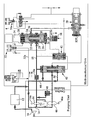
- Figure 1 is a diagram illustrating a fuel system in accordance with an embodiment of the invention.
- the fuel system illustrated diagrammatically in Figure 1 comprises a low pressure pump 10 arranged to supply fuel through a filter 12 to the inlet 14 of a primary gear pump 16.
- the pump 16 supplies fuel through a supply line 18 in which is located a flow washed filter 18 a to an inlet port 20 of a metering valve 22.
- the metering valve 22 is of substantially conventional form and comprises a valve member in the form of a spool 24 movable within a bore 26 under the influence of the fuel pressures within chambers 28, 30 formed at the ends of the spool 24.
- a servo valve arrangement 32 is used to control the relative pressures applied to the chambers 28, 30. For example, if it is desired to lift the spool 24, in the orientation illustrated, the chamber 30 is supplied with fuel at a higher pressure than that of chamber 28 by reducing the communication between the chamber 30 and the low pressure in line 32 a and increasing the communication between the chamber 28 and the low pressure in line 32 a .
- a position sensor 34 for example in the form of an LVDT is provided to monitor the position occupied by the spool 24, the output of the sensor 34 being used in the control of the operation of the servo valve 32 so as to allow the operation of the metering valve 22 to be controlled in a closed-loop fashion.
- the metering valve 22 includes an outlet port 36 connected through a pressure raising and shut-off valve 38 to the burners of an aircraft engine.
- the spool 24 partially obscures the outlet 36, and the rate at which fuel is able to flow through the metering valve 22 is dependent upon the position occupied by the spool 24. It will be appreciated that by lifting the spool 24, the fuel supply rate is increased, downward movement of the spool 24 reducing the fuel supply rate, the spool 24 being movable to a position in which the supply of fuel through the metering valve is terminated.
- a combining spill valve arrangement 40 is provided and is operable to maintain a substantially uniform pressure drop across the metering valve 22. In the event that the pressure drop across the metering valve 22 exceeds a predetermined level, a pressure drop control valve 42 causes the combining spill valve 40 to open thereby allowing fuel to escape along a return path 44 back to the inlet 14 of the fuel pump 16.
- the fuel system further comprises a second fuel pump 46 arranged to deliver fuel to the filter 18 and metering valve 22 through a non-return valve 48 under certain operating conditions of the engine.
- a second fuel pump 46 arranged to deliver fuel to the filter 18 and metering valve 22 through a non-return valve 48 under certain operating conditions of the engine.
- a pressure relief valve 52 is provided between the outlet of the pump 16 and the inlet 14 thereof, the pressure relief valve 52 opening in the event of excessive pressures occurring at the outlet of the pump 16 in order to reduce the risk of damage thereto.
- the fuel system illustrated in Figure 1 further comprises a dump valve 54 operable, on engine shut-down, to drain fuel from the burner manifold.
- the dump valve 54 comprises a valve member 56 movable by the spool 24 of the metering valve 22 when the spool 24 is moved to its fully closed position, such movement of the dump valve member 56 opening the dump valve to allow such escape of fuel.
- the dump valve member 56 is biassed by a spring 58 towards a closed position and so other than when forced to its open position by the spool 24, the dump valve 54 will remain closed.
- fuel is supplied by the pump 16 through the metering valve 22 and the pressure raising and shut-off valve 38 to the burners of the engine.
- the pump 16 is driven from an output shaft of the engine and rotates at a speed proportional to engine speed. It will be appreciated, therefore, that the rate of fuel supply by the pump 16 is governed by the speed of operation of the engine.
- the fuel supply to the engine is controlled by the metering valve 22 which, in turn, is controlled by the operation of the servo valve 32.
- the combining spill valve 40 together with the operation of the pressure drop control valve 42 maintains a substantially constant pressure drop across the metering valve 22 thus ensuring that the rate at which fuel is supplied by the metering valve 22 is governed by the axial position of the spool 24.
- the fuel system operates substantially conventionally and so further detail of its operation is not included herein.
- the pressure raising and shut-off valve 38 is closed by a shut-off servo valve 38 a to terminate fuel supply to the engine burners.
- the metering valve 22 is also closed by supplying the chamber 28 of the metering valve 22 with fuel under pressure, the chamber 30 being connected to low pressure by the servo valve 32. It will be appreciated that under these circumstances the spool 24 is forced downwardly in the orientation illustrated, thus closing the outlet 36. The operation of moving the spool 24 downwards brings the spool 24 into engagement with the dump valve member 56, forcing the dump valve member 56 away from its seating against the action of the spring 58 and opening the dump valve 54 thereby allowing fuel to escape from the burner manifold. Engine shut down in this manner is, again, substantially conventional and will not be described in further detail.
- the engine is turned by an external drive, resulting in the fuel pumps 16, 46 being driven.
- the fuel pressure to which the combining spill valve 40 is exposed is relatively low so the spill valve 40 occupies a closed position in which the second pump 46 is unloaded and in which none of the fuel supplied by the primary pump 16 and the secondary pump 46 is returned through the lines 44 and 50.
- the servo valve 32 is held in a position in which the chamber 30 is held at a lower pressure than chamber 28.
- the chamber 28 is exposed to a pressure related to the pressure of the fuel supplied by the pump 16 to the line 18. It will be appreciated, therefore, that the spool 24 is urged downwardly towards its closed position by the pressure differential. Initially, the difference in pressure is relatively small and so the spool 24, although urged into engagement with the dump valve member 56, is unable to move the dump valve member 56 against the action of the spring 58.
- the further movement of the spool 24 is sensed by the sensor 34, and the engine/pump operating speed at the time of the further movement being sensed is measured, for example by sensing the operating speed of the engine or the external drive used to rotate the engine at this time, or using sensors 16 a , 46 a associated with the pumps.
- the measured speed may be used directly to provide an indication of the wear status of the pump, it is envisaged to store the measured speed data over time to allow a wear profile to be built up which can be used to monitor pump wear and to allow scheduling of pump replacement at the optimum time.
- the speed data may be stored with other data which could impact upon the pump operating speed required to develop the required pressure, for example altitude and fuel temperature.
- the metering valve 22 can be opened to commence fuel supply to the pressure raising and shut-off valve 38 to allow engine start-up to continue in the usual manner.
- the method could form part of a separate pump test procedure if desired.
- the invention may be retrofitted or implemented in existing fuel systems without requiring the replacement or modification of significant components thereof. It therefore is of wide ranging application.
Abstract
Description
- The invention relates to a fuel system and in particular to a fuel system for use in supplying fuel to an aircraft engine. The invention relates, in particular to a method and apparatus for determining the operating characteristics, and in particular the extent of internal wear, of a fuel pump forming part of such a fuel system.
- A fuel system for use in the delivery of fuel to an aircraft engine typically comprises a primary constant displacement fuel pump arranged to supply fuel through a metering valve and a pressure raising and shut-off valve to the burners of an engine. A spill valve is arranged to maintain a substantially constant pressure drop across the metering valve by spilling fuel back to the inlet of the fuel pump. In some arrangements, a second pump is arranged to operate in parallel with the aforementioned primary pump to assist the primary pump during high demand phases of the engine operating cycle.
- In order to ensure a fuel pump is serviced or replaced at the optimum time, it is desirable to be able to monitor the extent of internal wear of the fuel pump without requiring the pump to be removed and dismantled.
- Techniques are described in
EP 1522731 ,EP 1138933 andUS 5111653 whereby the wear status of a fuel pump can be sensed by monitoring of the spill valve operation. However, the arrangements all require special designs of spill valve to be used. As a consequence they are unsuitable for retro-fitting into existing fuel systems. - It is an object of the invention to provide a method and apparatus whereby the disadvantages set out above can be overcome.
- According to the present invention there is provided a method of operating a fuel system to determine the extent of internal wear of a fuel pump thereof comprising driving the fuel pump, moving a metering valve member to a closed position in which it bears against a resilient stop, increasing the operating speed of the fuel pump to increase the pressure applied to the metering valve member urging it towards the resilient stop to a point beyond which further movement of the metering valve member occurs, sensing when the further movement of the metering valve member occurs, and sensing the operating speed of the pump at the time when said further movement occurs.
- The resilient stop is conveniently biassed by a spring, and preferably comprises a dump valve.
- The further movement of the metering valve member may be sensed by a position sensor used in normal control of the operation of the metering valve.
- The said further movement of the metering valve member occurs when the pressure applied thereto exceeds a substantially constant predetermined pressure. By monitoring the operating speed of the pump at which this pressure is attained, an indication as to the extent of internal leakage wear of the pump can be gained.
- Conveniently, the sensed operating speed is stored to allow a wear profile of the pump to be built up over time. The stored data may be used to allow estimation of the remaining operating lifetime of the pump and scheduling of its replacement.
- Where a wear profile is built up over time, preferably other factors which may effect the pump operating speed required to cause the further movement of the metering valve member, for example altitude and fuel temperature, are taken into account.
- The invention also relates to a fuel system comprising a fuel pump operable to supply fuel to a metering valve, the metering valve comprising a valve member movable under the influence of the fuel pressure applied thereto, a resilient stop limiting closing movement of the metering valve member when the pressure applied thereto is less than a predetermined level and allowing further movement of the metering valve member to occur when the applied pressure exceeds the predetermined level, sensor means for sensing said further movement of the metering valve member, and means operable to sense the operating speed of the fuel pump when said further movement of the metering valve member occurs.
- The movable stop conveniently comprises a dump valve.
- The method of the invention may be incorporated into the normal engine start procedure, and is suitable for retrofitting into existing systems.
- The invention will further be described, by way of example, with reference to the accompanying drawing (Figure 1) which is a diagram illustrating a fuel system in accordance with an embodiment of the invention.
- The fuel system illustrated diagrammatically in Figure 1 comprises a
low pressure pump 10 arranged to supply fuel through afilter 12 to theinlet 14 of aprimary gear pump 16. Thepump 16 supplies fuel through asupply line 18 in which is located a flow washedfilter 18a to aninlet port 20 of ametering valve 22. - The
metering valve 22 is of substantially conventional form and comprises a valve member in the form of aspool 24 movable within abore 26 under the influence of the fuel pressures withinchambers spool 24. Aservo valve arrangement 32 is used to control the relative pressures applied to thechambers spool 24, in the orientation illustrated, thechamber 30 is supplied with fuel at a higher pressure than that ofchamber 28 by reducing the communication between thechamber 30 and the low pressure inline 32a and increasing the communication between thechamber 28 and the low pressure inline 32a. Conversely, downward movement of thespool 24 is achieved by supplyingchamber 28 with fuel at a high pressure than that ofchamber 30 by increasing communication betweenchamber 30 and the low pressure inline 32a and reducing communication betweenchamber 28 and the low pressure inline 32a. Aposition sensor 34, for example in the form of an LVDT is provided to monitor the position occupied by thespool 24, the output of thesensor 34 being used in the control of the operation of theservo valve 32 so as to allow the operation of themetering valve 22 to be controlled in a closed-loop fashion. - As illustrated, the
metering valve 22 includes anoutlet port 36 connected through a pressure raising and shut-offvalve 38 to the burners of an aircraft engine. Thespool 24 partially obscures theoutlet 36, and the rate at which fuel is able to flow through themetering valve 22 is dependent upon the position occupied by thespool 24. It will be appreciated that by lifting thespool 24, the fuel supply rate is increased, downward movement of thespool 24 reducing the fuel supply rate, thespool 24 being movable to a position in which the supply of fuel through the metering valve is terminated. - A combining
spill valve arrangement 40 is provided and is operable to maintain a substantially uniform pressure drop across themetering valve 22. In the event that the pressure drop across themetering valve 22 exceeds a predetermined level, a pressuredrop control valve 42 causes the combiningspill valve 40 to open thereby allowing fuel to escape along areturn path 44 back to theinlet 14 of thefuel pump 16. - As illustrated, the fuel system further comprises a
second fuel pump 46 arranged to deliver fuel to thefilter 18 andmetering valve 22 through anon-return valve 48 under certain operating conditions of the engine. When delivery of fuel by thesecond fuel pump 46 is not required, then fuel delivered thereby is returned through thespill valve 40 and areturn passage 50 to the inlet of thepump 16 thus unloading thesecond pump 46. - A
pressure relief valve 52 is provided between the outlet of thepump 16 and theinlet 14 thereof, thepressure relief valve 52 opening in the event of excessive pressures occurring at the outlet of thepump 16 in order to reduce the risk of damage thereto. - The fuel system illustrated in Figure 1 further comprises a
dump valve 54 operable, on engine shut-down, to drain fuel from the burner manifold. Thedump valve 54 comprises avalve member 56 movable by thespool 24 of themetering valve 22 when thespool 24 is moved to its fully closed position, such movement of thedump valve member 56 opening the dump valve to allow such escape of fuel. As illustrated, thedump valve member 56 is biassed by aspring 58 towards a closed position and so other than when forced to its open position by thespool 24, thedump valve 54 will remain closed. - In normal use of the fuel system, fuel is supplied by the
pump 16 through themetering valve 22 and the pressure raising and shut-offvalve 38 to the burners of the engine. Thepump 16 is driven from an output shaft of the engine and rotates at a speed proportional to engine speed. It will be appreciated, therefore, that the rate of fuel supply by thepump 16 is governed by the speed of operation of the engine. The fuel supply to the engine is controlled by themetering valve 22 which, in turn, is controlled by the operation of theservo valve 32. As described hereinbefore, the combiningspill valve 40 together with the operation of the pressuredrop control valve 42 maintains a substantially constant pressure drop across themetering valve 22 thus ensuring that the rate at which fuel is supplied by themetering valve 22 is governed by the axial position of thespool 24. During this mode of operation, the fuel system operates substantially conventionally and so further detail of its operation is not included herein. - When it is desired to shut down the engine, the pressure raising and shut-off
valve 38 is closed by a shut-offservo valve 38a to terminate fuel supply to the engine burners. Themetering valve 22 is also closed by supplying thechamber 28 of themetering valve 22 with fuel under pressure, thechamber 30 being connected to low pressure by theservo valve 32. It will be appreciated that under these circumstances thespool 24 is forced downwardly in the orientation illustrated, thus closing theoutlet 36. The operation of moving thespool 24 downwards brings thespool 24 into engagement with thedump valve member 56, forcing thedump valve member 56 away from its seating against the action of thespring 58 and opening thedump valve 54 thereby allowing fuel to escape from the burner manifold. Engine shut down in this manner is, again, substantially conventional and will not be described in further detail. - To start the engine, the engine is turned by an external drive, resulting in the
fuel pumps spill valve 40 is exposed is relatively low so thespill valve 40 occupies a closed position in which thesecond pump 46 is unloaded and in which none of the fuel supplied by theprimary pump 16 and thesecondary pump 46 is returned through thelines servo valve 32 is held in a position in which thechamber 30 is held at a lower pressure thanchamber 28. Thechamber 28 is exposed to a pressure related to the pressure of the fuel supplied by thepump 16 to theline 18. It will be appreciated, therefore, that thespool 24 is urged downwardly towards its closed position by the pressure differential. Initially, the difference in pressure is relatively small and so thespool 24, although urged into engagement with thedump valve member 56, is unable to move thedump valve member 56 against the action of thespring 58. - The speed at which the engine, and hence the
pump 16, is driven is increased, with the result that the fuel pressure in theline 18, and hence in thechamber 28, increases and a point will be reached at which the pressure applied to thespool 24 is sufficient to overcome the action of thespring 58, thus thespool 24 is able to move further in the downward direction. This movement is accompanied by opening movement of thedump valve member 56 but as no fuel is being supplied to the burners at this point, such operation of thedump valve 54 is of no effect. - The further movement of the
spool 24 is sensed by thesensor 34, and the engine/pump operating speed at the time of the further movement being sensed is measured, for example by sensing the operating speed of the engine or the external drive used to rotate the engine at this time, or usingsensors - As the force applied by the
spring 58 is substantially constant over the working life of the fuel system, it will be appreciated that the technique described hereinbefore can be used to provide an indication of the pump operating speed necessary to develop a substantially fixed pressure. Increases in the required operating speed are representative of internal wear and hence leakage of fuel from the outlet side of the pump, in this case the combination of the primary and secondary pumps and so the leakage could be in either or both of these pumps, to the inlet side thereof. - Although the measured speed may be used directly to provide an indication of the wear status of the pump, it is envisaged to store the measured speed data over time to allow a wear profile to be built up which can be used to monitor pump wear and to allow scheduling of pump replacement at the optimum time. The speed data may be stored with other data which could impact upon the pump operating speed required to develop the required pressure, for example altitude and fuel temperature.
- After having sensed the pump wear status, the
metering valve 22 can be opened to commence fuel supply to the pressure raising and shut-offvalve 38 to allow engine start-up to continue in the usual manner. - Although described as part of the engine start-up procedure, the method could form part of a separate pump test procedure if desired.
- It will be appreciated that the invention may be retrofitted or implemented in existing fuel systems without requiring the replacement or modification of significant components thereof. It therefore is of wide ranging application.
- A number of modifications or alterations may be made to the arrangement described hereinbefore. For example, although the dump valve conveniently forms the resilient stop, particularly when being retrofitted, arrangements are possible in which a separate spring biassed resilient stop is provided. Further, although described as part of a system in which fuel is supplied by a pumping unit having two pumps arranged in parallel to sense the wear status of the pumping unit, the invention is also applicable to single pump systems.
Claims (11)
- A method of operating a fuel system to determine the extent of internal wear of a fuel pump (14, 46) thereof comprising driving the fuel pump (16, 46), moving a metering valve member (24) to a closed position in which it bears against a resilient stop (56), increasing the operating speed of the fuel pump (16, 46) to increase the pressure applied to the metering valve member (24) urging it towards the resilient stop (56) to a point beyond which further movement of the metering valve member (24) occurs, sensing when the further movement of the metering valve member (24) occurs, and sensing the operating speed of the pump (16, 46) at the time when said further movement occurs.
- A method according to Claim 1, wherein the resilient stop (56) is biassed by a spring (58).
- A method according to Claim 1 or Claim 2, wherein the resilient stop comprises a dump valve (56).
- A method according to any of the preceding claims, wherein the further movement of the metering valve member (24) is sensed by a position sensor (34) used in normal control of the operation of the metering valve (24).
- A method according to any of the preceding claims, wherein the sensed operating speed is stored to allow a wear profile of the pump to be built up over time.
- A method according to Claim 5, wherein the stored data is used to allow estimation of the remaining operating lifetime of the pump and scheduling of its replacement.
- A method according to Claim 5 or Claim 6, wherein data representative of other factors which may effect the pump operating speed required to cause the further movement of the metering valve member is stored.
- A method according to Claim 7, wherein the said other factors comprise at least one of altitude and fuel temperature.
- A fuel system comprising a fuel pump (16, 46) operable to supply fuel to a metering valve (22), the metering valve (22) comprising a valve member (24) movable under the influence of the fuel pressure applied thereto, a resilient stop (56) limiting closing movement of the metering valve member (24) when the pressure applied thereto is less than a predetermined level and allowing further movement of the metering valve member (24) to occur when the applied pressure exceeds the predetermined level, sensor means (34) for sensing said further movement of the metering valve member (24), and means operable to sense the operating speed of the fuel pump (16, 46) when said further movement of the metering valve member (24) occurs.
- A fuel system according to Claim 9, wherein the resilient step (56) is spring biassed.
- A fuel system according to Claim 9 or Claim 10, wherein the resilient stop comprises a dump valve (56).
Applications Claiming Priority (1)
| Application Number | Priority Date | Filing Date | Title |
|---|---|---|---|
| GBGB0522991.9A GB0522991D0 (en) | 2005-11-11 | 2005-11-11 | Fuel system |
Publications (3)
| Publication Number | Publication Date |
|---|---|
| EP1785348A2 true EP1785348A2 (en) | 2007-05-16 |
| EP1785348A3 EP1785348A3 (en) | 2009-04-22 |
| EP1785348B1 EP1785348B1 (en) | 2011-06-22 |
Family
ID=35516740
Family Applications (1)
| Application Number | Title | Priority Date | Filing Date |
|---|---|---|---|
| EP06255472A Expired - Fee Related EP1785348B1 (en) | 2005-11-11 | 2006-10-24 | Fuel system and method for determining the extent of internal wear of a fuel pump |
Country Status (3)
| Country | Link |
|---|---|
| US (1) | US7481102B2 (en) |
| EP (1) | EP1785348B1 (en) |
| GB (1) | GB0522991D0 (en) |
Cited By (8)
| Publication number | Priority date | Publication date | Assignee | Title |
|---|---|---|---|---|
| FR2923871A1 (en) * | 2007-11-19 | 2009-05-22 | Hispano Suiza Sa | High-pressure pump monitoring device for e.g. jet engine, of aircraft, has comparing unit for comparing value with predetermined threshold to direct replacement of high-pressure pump in fuel supply circuit when value attains threshold |
| EP2339147A3 (en) * | 2009-12-22 | 2012-07-11 | Rolls-Royce Goodrich Engine Control Systems Ltd. | Fuel supply control system for an aircraft engine |
| FR2971563A1 (en) * | 2011-02-15 | 2012-08-17 | Snecma | Method for determining whether hydraulic fuel supply pump or low pressure hydraulic pump of aircraft is out-of-service or not, involves determining operating state of pumps if fluid pressure is low for rotational speeds of turbomachine |
| GB2492230A (en) * | 2011-06-22 | 2012-12-26 | Hamilton Sundstrand Corp | Fuel system health monitoring |
| FR2979957A1 (en) * | 2011-09-13 | 2013-03-15 | Snecma | METHOD FOR MONITORING THE VOLUMETRIC PERFORMANCE OF AN HP PUMP OF A HYDRAULIC TURBOMACHINE REGULATION SYSTEM |
| EP2891768A1 (en) * | 2014-01-06 | 2015-07-08 | Rolls-Royce Controls and Data Services Limited | Engine fuel control system |
| WO2016048787A1 (en) * | 2014-09-23 | 2016-03-31 | Woodward, Inc. | Pump authority switching apparatus for a fluid distribution system |
| CN107740763A (en) * | 2017-09-11 | 2018-02-27 | 郑州斯倍思机电有限公司 | A kind of lubricating oil pump delivery-inspection test platform and its operating method |
Families Citing this family (7)
| Publication number | Priority date | Publication date | Assignee | Title |
|---|---|---|---|---|
| FR3013837B1 (en) * | 2013-11-25 | 2015-12-18 | Snecma | METHOD FOR TESTING VARIABLE GEOMETRY EQUIPMENTS OF AN AIRCRAFT ENGINE, IN PARTICULAR TURBOMACHINE |
| FR3028245B1 (en) * | 2014-11-06 | 2019-05-24 | Airbus Operations | FUEL SUPPLY CIRCUIT OF AN AIRCRAFT |
| WO2019172372A1 (en) | 2018-03-08 | 2019-09-12 | 株式会社Ihi | Fuel supply control device |
| CN110318886A (en) * | 2019-07-16 | 2019-10-11 | 中国航发沈阳发动机研究所 | A kind of fuel metering system and its matching process based on duplex gear pump |
| CN110735723B (en) * | 2019-10-22 | 2022-03-08 | 北京动力机械研究所 | Position retaining system for flow regulating valve after abnormal power failure of engine controller |
| CN111022689B (en) * | 2019-11-21 | 2022-05-17 | 中国航发西安动力控制科技有限公司 | Fuel metering mechanism capable of realizing accurate control |
| US11598302B2 (en) * | 2020-11-24 | 2023-03-07 | Caterpillar Inc. | Fuel pump health assessment system |
Citations (4)
| Publication number | Priority date | Publication date | Assignee | Title |
|---|---|---|---|---|
| EP0915241A2 (en) * | 1997-11-07 | 1999-05-12 | LUCAS INDUSTRIES public limited company | Fuel flow shut-off system |
| US20050021213A1 (en) * | 2003-05-05 | 2005-01-27 | Miller Nathan Todd | Valve flow control system and method |
| US20050016176A1 (en) * | 2003-07-25 | 2005-01-27 | Michael Griffiths | Engine fuel control |
| EP1522731A2 (en) * | 2003-10-11 | 2005-04-13 | Goodrich Control Systems Ltd | Pump health monitoring |
Family Cites Families (3)
| Publication number | Priority date | Publication date | Assignee | Title |
|---|---|---|---|---|
| GB2061401B (en) * | 1979-09-15 | 1983-09-01 | Lucas Industries Ltd | Test equipment |
| GB0417034D0 (en) * | 2004-07-30 | 2004-09-01 | Goodrich Control Sys Ltd | Pressure regulator |
| GB0508126D0 (en) * | 2005-04-22 | 2005-06-01 | Goodrich Control Sys Ltd | Fuel system |
-
2005
- 2005-11-11 GB GBGB0522991.9A patent/GB0522991D0/en not_active Ceased
-
2006
- 2006-10-24 EP EP06255472A patent/EP1785348B1/en not_active Expired - Fee Related
- 2006-11-01 US US11/555,335 patent/US7481102B2/en not_active Expired - Fee Related
Patent Citations (4)
| Publication number | Priority date | Publication date | Assignee | Title |
|---|---|---|---|---|
| EP0915241A2 (en) * | 1997-11-07 | 1999-05-12 | LUCAS INDUSTRIES public limited company | Fuel flow shut-off system |
| US20050021213A1 (en) * | 2003-05-05 | 2005-01-27 | Miller Nathan Todd | Valve flow control system and method |
| US20050016176A1 (en) * | 2003-07-25 | 2005-01-27 | Michael Griffiths | Engine fuel control |
| EP1522731A2 (en) * | 2003-10-11 | 2005-04-13 | Goodrich Control Systems Ltd | Pump health monitoring |
Cited By (24)
| Publication number | Priority date | Publication date | Assignee | Title |
|---|---|---|---|---|
| RU2495265C2 (en) * | 2007-11-19 | 2013-10-10 | Снекма | High-pressure pump control device at gas turbine feed circuit |
| WO2009101267A2 (en) | 2007-11-19 | 2009-08-20 | Snecma | Monitoring of a high‑pressure pump in a turbomachine fuel supply circuit |
| WO2009101267A3 (en) * | 2007-11-19 | 2009-10-22 | Snecma | Monitoring of a high‑pressure pump in a turbine engine fuel supply circuit |
| CN101861451A (en) * | 2007-11-19 | 2010-10-13 | 斯奈克玛 | Monitoring of a high-pressure pump in a turbomachine fuel supply circuit |
| US8857150B2 (en) | 2007-11-19 | 2014-10-14 | Snecma | Monitoring of a high-pressure pump in a turbine engine fuel supply circuit |
| CN101861451B (en) * | 2007-11-19 | 2015-01-28 | 斯奈克玛 | Monitoring of a high-pressure pump in a turbomachine fuel supply circuit |
| FR2923871A1 (en) * | 2007-11-19 | 2009-05-22 | Hispano Suiza Sa | High-pressure pump monitoring device for e.g. jet engine, of aircraft, has comparing unit for comparing value with predetermined threshold to direct replacement of high-pressure pump in fuel supply circuit when value attains threshold |
| EP2339147A3 (en) * | 2009-12-22 | 2012-07-11 | Rolls-Royce Goodrich Engine Control Systems Ltd. | Fuel supply control system for an aircraft engine |
| US8991186B2 (en) | 2009-12-22 | 2015-03-31 | Rolls-Royce Engine Control Systems Limited | Fuel control system with servo valve controlled windmill relight mode |
| FR2971563A1 (en) * | 2011-02-15 | 2012-08-17 | Snecma | Method for determining whether hydraulic fuel supply pump or low pressure hydraulic pump of aircraft is out-of-service or not, involves determining operating state of pumps if fluid pressure is low for rotational speeds of turbomachine |
| GB2492230A (en) * | 2011-06-22 | 2012-12-26 | Hamilton Sundstrand Corp | Fuel system health monitoring |
| US8578763B2 (en) | 2011-06-22 | 2013-11-12 | Hamilton Sundstrand Corporation | System and method for fuel system health monitoring |
| GB2492230B (en) * | 2011-06-22 | 2013-10-09 | Hamilton Sundstrand Corp | System and method for fuel system health monitoring |
| WO2013038085A3 (en) * | 2011-09-13 | 2014-03-20 | Snecma | Method for monitoring the volumetric efficiency of an hp pump of a turbomachine hydraulic regulation system |
| CN103917783A (en) * | 2011-09-13 | 2014-07-09 | 斯奈克玛 | Method for monitoring the volumetric efficiency of an hp pump of a turbomachine hydraulic regulation system |
| WO2013038085A2 (en) * | 2011-09-13 | 2013-03-21 | Snecma | Method for monitoring the volumetric efficiency of an hp pump of a turbomachine hydraulic regulation system |
| FR2979957A1 (en) * | 2011-09-13 | 2013-03-15 | Snecma | METHOD FOR MONITORING THE VOLUMETRIC PERFORMANCE OF AN HP PUMP OF A HYDRAULIC TURBOMACHINE REGULATION SYSTEM |
| US9309882B2 (en) | 2011-09-13 | 2016-04-12 | Snecma | Method of determining whether to replace a high pressure pump in a hydraulic regulation system of a turbomachine |
| RU2606465C2 (en) * | 2011-09-13 | 2017-01-10 | Снекма | Method of high pressure (hp) positive displacement pump efficiency monitoring in turbomachine hydraulic regulation system |
| EP2891768A1 (en) * | 2014-01-06 | 2015-07-08 | Rolls-Royce Controls and Data Services Limited | Engine fuel control system |
| US9739208B2 (en) | 2014-01-06 | 2017-08-22 | Rolls-Royce Plc | Engine fuel control system |
| WO2016048787A1 (en) * | 2014-09-23 | 2016-03-31 | Woodward, Inc. | Pump authority switching apparatus for a fluid distribution system |
| US9850917B2 (en) | 2014-09-23 | 2017-12-26 | Woodward, Inc. | Pump authority switching apparatus for a fluid distribution system |
| CN107740763A (en) * | 2017-09-11 | 2018-02-27 | 郑州斯倍思机电有限公司 | A kind of lubricating oil pump delivery-inspection test platform and its operating method |
Also Published As
| Publication number | Publication date |
|---|---|
| EP1785348A3 (en) | 2009-04-22 |
| US20070107435A1 (en) | 2007-05-17 |
| GB0522991D0 (en) | 2005-12-21 |
| EP1785348B1 (en) | 2011-06-22 |
| US7481102B2 (en) | 2009-01-27 |
Similar Documents
| Publication | Publication Date | Title |
|---|---|---|
| EP1785348B1 (en) | Fuel system and method for determining the extent of internal wear of a fuel pump | |
| US8720482B2 (en) | Fuel system | |
| RU2398124C2 (en) | Gas turbine engine fuel feed device with adjustable fuel flow rate | |
| US8857150B2 (en) | Monitoring of a high-pressure pump in a turbine engine fuel supply circuit | |
| JP5100398B2 (en) | Aircraft engine fuel supply | |
| US9771906B2 (en) | Engine fuel control system | |
| JP4321342B2 (en) | Common rail fuel injection system | |
| EP2417383B1 (en) | Flow sensing shutoff valve | |
| EP1522731B1 (en) | Pump health monitoring | |
| EP2339147A2 (en) | Fuel supply control system for an aircraft engine | |
| EP2762711B1 (en) | Engine fuel control system | |
| WO2005075813A1 (en) | Fuel supply device | |
| EP1198664B1 (en) | Draining device for the fuel supply system of a gas turbine engine | |
| JP2005061399A (en) | Lubricating device and lubricating method | |
| JP2001527181A (en) | Start / Shutdown / Overspeed system | |
| EP1978224A2 (en) | Fuel system | |
| CN103261644A (en) | Fuel injection system of internal combustion engine, and associated pressure regulating method | |
| US5086617A (en) | Gas turbine engine fuel control system, and metering valve | |
| JP2008138566A (en) | Fuel injection device and operating method for engine | |
| EP2479408A2 (en) | Aircraft engine fuel system | |
| US20100121553A1 (en) | Engine Relight Method | |
| CN106321317B (en) | Method for determining operating parameters of a fuel pump | |
| EP1944486B1 (en) | Aircraft fuel system | |
| JP2008163806A (en) | Fuel pressure accumulating device and fuel injection device | |
| RU43595U1 (en) | FUEL SUPPLY SYSTEM FOR GAS-TURBINE ENGINE |
Legal Events
| Date | Code | Title | Description |
|---|---|---|---|
| PUAI | Public reference made under article 153(3) epc to a published international application that has entered the european phase |
Free format text: ORIGINAL CODE: 0009012 |
|
| AK | Designated contracting states |
Kind code of ref document: A2 Designated state(s): AT BE BG CH CY CZ DE DK EE ES FI FR GB GR HU IE IS IT LI LT LU LV MC NL PL PT RO SE SI SK TR |
|
| AX | Request for extension of the european patent |
Extension state: AL BA HR MK YU |
|
| PUAL | Search report despatched |
Free format text: ORIGINAL CODE: 0009013 |
|
| AK | Designated contracting states |
Kind code of ref document: A3 Designated state(s): AT BE BG CH CY CZ DE DK EE ES FI FR GB GR HU IE IS IT LI LT LU LV MC NL PL PT RO SE SI SK TR |
|
| AX | Request for extension of the european patent |
Extension state: AL BA HR MK RS |
|
| RIC1 | Information provided on ipc code assigned before grant |
Ipc: B64D 37/00 20060101AFI20070214BHEP Ipc: F04C 14/00 20060101ALI20090319BHEP Ipc: F02C 9/26 20060101ALI20090319BHEP Ipc: F02M 37/00 20060101ALI20090319BHEP |
|
| 17P | Request for examination filed |
Effective date: 20091008 |
|
| AKX | Designation fees paid |
Designated state(s): DE ES FR GB IT |
|
| GRAP | Despatch of communication of intention to grant a patent |
Free format text: ORIGINAL CODE: EPIDOSNIGR1 |
|
| RTI1 | Title (correction) |
Free format text: FUEL SYSTEM AND METHOD FOR DETERMINING THE EXTENT OF INTERNAL WEAR OF A FUEL PUMP |
|
| GRAS | Grant fee paid |
Free format text: ORIGINAL CODE: EPIDOSNIGR3 |
|
| GRAA | (expected) grant |
Free format text: ORIGINAL CODE: 0009210 |
|
| AK | Designated contracting states |
Kind code of ref document: B1 Designated state(s): DE ES FR GB IT |
|
| REG | Reference to a national code |
Ref country code: GB Ref legal event code: FG4D |
|
| REG | Reference to a national code |
Ref country code: DE Ref legal event code: R096 Ref document number: 602006022636 Country of ref document: DE Effective date: 20110811 |
|
| PLBE | No opposition filed within time limit |
Free format text: ORIGINAL CODE: 0009261 |
|
| STAA | Information on the status of an ep patent application or granted ep patent |
Free format text: STATUS: NO OPPOSITION FILED WITHIN TIME LIMIT |
|
| 26N | No opposition filed |
Effective date: 20120323 |
|
| PG25 | Lapsed in a contracting state [announced via postgrant information from national office to epo] |
Ref country code: IT Free format text: LAPSE BECAUSE OF FAILURE TO SUBMIT A TRANSLATION OF THE DESCRIPTION OR TO PAY THE FEE WITHIN THE PRESCRIBED TIME-LIMIT Effective date: 20110622 |
|
| REG | Reference to a national code |
Ref country code: DE Ref legal event code: R097 Ref document number: 602006022636 Country of ref document: DE Effective date: 20120323 |
|
| PGFP | Annual fee paid to national office [announced via postgrant information from national office to epo] |
Ref country code: FR Payment date: 20121018 Year of fee payment: 7 Ref country code: DE Payment date: 20121017 Year of fee payment: 7 |
|
| PGFP | Annual fee paid to national office [announced via postgrant information from national office to epo] |
Ref country code: GB Payment date: 20121024 Year of fee payment: 7 |
|
| PG25 | Lapsed in a contracting state [announced via postgrant information from national office to epo] |
Ref country code: ES Free format text: LAPSE BECAUSE OF FAILURE TO SUBMIT A TRANSLATION OF THE DESCRIPTION OR TO PAY THE FEE WITHIN THE PRESCRIBED TIME-LIMIT Effective date: 20111003 |
|
| REG | Reference to a national code |
Ref country code: DE Ref legal event code: R081 Ref document number: 602006022636 Country of ref document: DE Owner name: GOODRICH CONTROL SYSTEMS, GB Free format text: FORMER OWNER: GOODRICH CONTROL SYSTEMS LTD., SOLIHULL, GB Effective date: 20140220 Ref country code: DE Ref legal event code: R082 Ref document number: 602006022636 Country of ref document: DE Representative=s name: MARKS & CLERK (LUXEMBOURG) LLP, LU Effective date: 20140220 Ref country code: DE Ref legal event code: R081 Ref document number: 602006022636 Country of ref document: DE Owner name: GOODRICH CONTROL SYSTEMS, GB Free format text: FORMER OWNER: GOODRICH CONTROL SYSTEMS LTD., SOLIHULL, GB Effective date: 20110620 Ref country code: DE Ref legal event code: R081 Ref document number: 602006022636 Country of ref document: DE Owner name: GOODRICH CONTROL SYSTEMS, SOLIHULL, GB Free format text: FORMER OWNER: GOODRICH CONTROL SYSTEMS LTD., SOLIHULL, WEST MIDLANDS, GB Effective date: 20140220 Ref country code: DE Ref legal event code: R081 Ref document number: 602006022636 Country of ref document: DE Owner name: GOODRICH CONTROL SYSTEMS, SOLIHULL, GB Free format text: FORMER OWNER: GOODRICH CONTROL SYSTEMS LTD., SOLIHULL, WEST MIDLANDS, GB Effective date: 20110620 |
|
| GBPC | Gb: european patent ceased through non-payment of renewal fee |
Effective date: 20131024 |
|
| PG25 | Lapsed in a contracting state [announced via postgrant information from national office to epo] |
Ref country code: GB Free format text: LAPSE BECAUSE OF NON-PAYMENT OF DUE FEES Effective date: 20131024 |
|
| REG | Reference to a national code |
Ref country code: FR Ref legal event code: ST Effective date: 20140630 |
|
| REG | Reference to a national code |
Ref country code: DE Ref legal event code: R119 Ref document number: 602006022636 Country of ref document: DE Effective date: 20140501 |
|
| PG25 | Lapsed in a contracting state [announced via postgrant information from national office to epo] |
Ref country code: FR Free format text: LAPSE BECAUSE OF NON-PAYMENT OF DUE FEES Effective date: 20131031 Ref country code: DE Free format text: LAPSE BECAUSE OF NON-PAYMENT OF DUE FEES Effective date: 20140501 |