EP1785214A2 - Method for creating a flange at the free end of a turbine blade, turbine blade obtained by the method and turbomachine equipped with said turbine blade - Google Patents
Method for creating a flange at the free end of a turbine blade, turbine blade obtained by the method and turbomachine equipped with said turbine blade Download PDFInfo
- Publication number
- EP1785214A2 EP1785214A2 EP06124100A EP06124100A EP1785214A2 EP 1785214 A2 EP1785214 A2 EP 1785214A2 EP 06124100 A EP06124100 A EP 06124100A EP 06124100 A EP06124100 A EP 06124100A EP 1785214 A2 EP1785214 A2 EP 1785214A2
- Authority
- EP
- European Patent Office
- Prior art keywords
- blade
- flange
- base
- rim
- free end
- Prior art date
- Legal status (The legal status is an assumption and is not a legal conclusion. Google has not performed a legal analysis and makes no representation as to the accuracy of the status listed.)
- Granted
Links
- 238000000034 method Methods 0.000 title claims abstract description 34
- 239000000463 material Substances 0.000 claims abstract description 71
- 239000000843 powder Substances 0.000 claims abstract description 44
- 230000003287 optical effect Effects 0.000 claims abstract description 27
- 230000015572 biosynthetic process Effects 0.000 claims abstract description 13
- 238000001816 cooling Methods 0.000 claims description 21
- 239000000203 mixture Substances 0.000 claims description 14
- 238000000576 coating method Methods 0.000 claims description 13
- 239000011248 coating agent Substances 0.000 claims description 11
- 239000011324 bead Substances 0.000 claims description 8
- 238000000151 deposition Methods 0.000 claims description 8
- FGUUSXIOTUKUDN-IBGZPJMESA-N C1(=CC=CC=C1)N1C2=C(NC([C@H](C1)NC=1OC(=NN=1)C1=CC=CC=C1)=O)C=CC=C2 Chemical compound C1(=CC=CC=C1)N1C2=C(NC([C@H](C1)NC=1OC(=NN=1)C1=CC=CC=C1)=O)C=CC=C2 FGUUSXIOTUKUDN-IBGZPJMESA-N 0.000 claims description 6
- GNFTZDOKVXKIBK-UHFFFAOYSA-N 3-(2-methoxyethoxy)benzohydrazide Chemical compound COCCOC1=CC=CC(C(=O)NN)=C1 GNFTZDOKVXKIBK-UHFFFAOYSA-N 0.000 claims description 2
- 230000003213 activating effect Effects 0.000 claims description 2
- 239000012254 powdered material Substances 0.000 claims 1
- 229910052751 metal Inorganic materials 0.000 abstract description 8
- 239000002184 metal Substances 0.000 abstract description 8
- 230000008021 deposition Effects 0.000 abstract description 7
- 238000010276 construction Methods 0.000 description 13
- 239000007789 gas Substances 0.000 description 10
- 238000007751 thermal spraying Methods 0.000 description 9
- PXHVJJICTQNCMI-UHFFFAOYSA-N Nickel Chemical compound [Ni] PXHVJJICTQNCMI-UHFFFAOYSA-N 0.000 description 8
- 238000004519 manufacturing process Methods 0.000 description 7
- 239000003082 abrasive agent Substances 0.000 description 6
- 238000005266 casting Methods 0.000 description 6
- XEEYBQQBJWHFJM-UHFFFAOYSA-N Iron Chemical compound [Fe] XEEYBQQBJWHFJM-UHFFFAOYSA-N 0.000 description 4
- 229910045601 alloy Inorganic materials 0.000 description 4
- 239000000956 alloy Substances 0.000 description 4
- 230000006378 damage Effects 0.000 description 4
- 239000000155 melt Substances 0.000 description 4
- 150000002739 metals Chemical class 0.000 description 4
- 229910052759 nickel Inorganic materials 0.000 description 4
- 229910001069 Ti alloy Inorganic materials 0.000 description 3
- GWEVSGVZZGPLCZ-UHFFFAOYSA-N Titan oxide Chemical compound O=[Ti]=O GWEVSGVZZGPLCZ-UHFFFAOYSA-N 0.000 description 3
- PNEYBMLMFCGWSK-UHFFFAOYSA-N aluminium oxide Inorganic materials [O-2].[O-2].[O-2].[Al+3].[Al+3] PNEYBMLMFCGWSK-UHFFFAOYSA-N 0.000 description 3
- 239000010941 cobalt Substances 0.000 description 3
- 229910017052 cobalt Inorganic materials 0.000 description 3
- GUTLYIVDDKVIGB-UHFFFAOYSA-N cobalt atom Chemical compound [Co] GUTLYIVDDKVIGB-UHFFFAOYSA-N 0.000 description 3
- 238000003754 machining Methods 0.000 description 3
- 239000002245 particle Substances 0.000 description 3
- MCMNRKCIXSYSNV-UHFFFAOYSA-N Zirconium dioxide Chemical compound O=[Zr]=O MCMNRKCIXSYSNV-UHFFFAOYSA-N 0.000 description 2
- 230000001154 acute effect Effects 0.000 description 2
- 230000005540 biological transmission Effects 0.000 description 2
- 239000000919 ceramic Substances 0.000 description 2
- 238000006073 displacement reaction Methods 0.000 description 2
- 230000000694 effects Effects 0.000 description 2
- 229910052742 iron Inorganic materials 0.000 description 2
- 239000013307 optical fiber Substances 0.000 description 2
- 230000003647 oxidation Effects 0.000 description 2
- 238000007254 oxidation reaction Methods 0.000 description 2
- 229910000838 Al alloy Inorganic materials 0.000 description 1
- VYZAMTAEIAYCRO-UHFFFAOYSA-N Chromium Chemical compound [Cr] VYZAMTAEIAYCRO-UHFFFAOYSA-N 0.000 description 1
- 229910001347 Stellite Inorganic materials 0.000 description 1
- 238000005299 abrasion Methods 0.000 description 1
- 230000004913 activation Effects 0.000 description 1
- 238000013459 approach Methods 0.000 description 1
- QVGXLLKOCUKJST-UHFFFAOYSA-N atomic oxygen Chemical compound [O] QVGXLLKOCUKJST-UHFFFAOYSA-N 0.000 description 1
- 238000007664 blowing Methods 0.000 description 1
- 229910052804 chromium Inorganic materials 0.000 description 1
- 239000011651 chromium Substances 0.000 description 1
- QNHZQZQTTIYAQM-UHFFFAOYSA-N chromium tungsten Chemical compound [Cr][W] QNHZQZQTTIYAQM-UHFFFAOYSA-N 0.000 description 1
- AHICWQREWHDHHF-UHFFFAOYSA-N chromium;cobalt;iron;manganese;methane;molybdenum;nickel;silicon;tungsten Chemical compound C.[Si].[Cr].[Mn].[Fe].[Co].[Ni].[Mo].[W] AHICWQREWHDHHF-UHFFFAOYSA-N 0.000 description 1
- 229910052593 corundum Inorganic materials 0.000 description 1
- 230000003247 decreasing effect Effects 0.000 description 1
- 239000000835 fiber Substances 0.000 description 1
- 230000004927 fusion Effects 0.000 description 1
- 238000000227 grinding Methods 0.000 description 1
- 238000007749 high velocity oxygen fuel spraying Methods 0.000 description 1
- 239000001301 oxygen Substances 0.000 description 1
- 229910052760 oxygen Inorganic materials 0.000 description 1
- 230000002093 peripheral effect Effects 0.000 description 1
- 239000012255 powdered metal Substances 0.000 description 1
- 230000001737 promoting effect Effects 0.000 description 1
- 239000003380 propellant Substances 0.000 description 1
- 238000007789 sealing Methods 0.000 description 1
- 238000005507 spraying Methods 0.000 description 1
- 239000004408 titanium dioxide Substances 0.000 description 1
- MTPVUVINMAGMJL-UHFFFAOYSA-N trimethyl(1,1,2,2,2-pentafluoroethyl)silane Chemical compound C[Si](C)(C)C(F)(F)C(F)(F)F MTPVUVINMAGMJL-UHFFFAOYSA-N 0.000 description 1
- 238000011144 upstream manufacturing Methods 0.000 description 1
- 229910001845 yogo sapphire Inorganic materials 0.000 description 1
Images


Classifications
-
- B—PERFORMING OPERATIONS; TRANSPORTING
- B23—MACHINE TOOLS; METAL-WORKING NOT OTHERWISE PROVIDED FOR
- B23K—SOLDERING OR UNSOLDERING; WELDING; CLADDING OR PLATING BY SOLDERING OR WELDING; CUTTING BY APPLYING HEAT LOCALLY, e.g. FLAME CUTTING; WORKING BY LASER BEAM
- B23K26/00—Working by laser beam, e.g. welding, cutting or boring
- B23K26/34—Laser welding for purposes other than joining
-
- B—PERFORMING OPERATIONS; TRANSPORTING
- B22—CASTING; POWDER METALLURGY
- B22F—WORKING METALLIC POWDER; MANUFACTURE OF ARTICLES FROM METALLIC POWDER; MAKING METALLIC POWDER; APPARATUS OR DEVICES SPECIALLY ADAPTED FOR METALLIC POWDER
- B22F10/00—Additive manufacturing of workpieces or articles from metallic powder
- B22F10/20—Direct sintering or melting
- B22F10/25—Direct deposition of metal particles, e.g. direct metal deposition [DMD] or laser engineered net shaping [LENS]
-
- B—PERFORMING OPERATIONS; TRANSPORTING
- B22—CASTING; POWDER METALLURGY
- B22F—WORKING METALLIC POWDER; MANUFACTURE OF ARTICLES FROM METALLIC POWDER; MAKING METALLIC POWDER; APPARATUS OR DEVICES SPECIALLY ADAPTED FOR METALLIC POWDER
- B22F10/00—Additive manufacturing of workpieces or articles from metallic powder
- B22F10/30—Process control
- B22F10/38—Process control to achieve specific product aspects, e.g. surface smoothness, density, porosity or hollow structures
- B22F10/385—Overhang structures
-
- B—PERFORMING OPERATIONS; TRANSPORTING
- B22—CASTING; POWDER METALLURGY
- B22F—WORKING METALLIC POWDER; MANUFACTURE OF ARTICLES FROM METALLIC POWDER; MAKING METALLIC POWDER; APPARATUS OR DEVICES SPECIALLY ADAPTED FOR METALLIC POWDER
- B22F12/00—Apparatus or devices specially adapted for additive manufacturing; Auxiliary means for additive manufacturing; Combinations of additive manufacturing apparatus or devices with other processing apparatus or devices
- B22F12/50—Means for feeding of material, e.g. heads
- B22F12/53—Nozzles
-
- B—PERFORMING OPERATIONS; TRANSPORTING
- B22—CASTING; POWDER METALLURGY
- B22F—WORKING METALLIC POWDER; MANUFACTURE OF ARTICLES FROM METALLIC POWDER; MAKING METALLIC POWDER; APPARATUS OR DEVICES SPECIALLY ADAPTED FOR METALLIC POWDER
- B22F12/00—Apparatus or devices specially adapted for additive manufacturing; Auxiliary means for additive manufacturing; Combinations of additive manufacturing apparatus or devices with other processing apparatus or devices
- B22F12/50—Means for feeding of material, e.g. heads
- B22F12/58—Means for feeding of material, e.g. heads for changing the material composition, e.g. by mixing
-
- B—PERFORMING OPERATIONS; TRANSPORTING
- B22—CASTING; POWDER METALLURGY
- B22F—WORKING METALLIC POWDER; MANUFACTURE OF ARTICLES FROM METALLIC POWDER; MAKING METALLIC POWDER; APPARATUS OR DEVICES SPECIALLY ADAPTED FOR METALLIC POWDER
- B22F5/00—Manufacture of workpieces or articles from metallic powder characterised by the special shape of the product
- B22F5/04—Manufacture of workpieces or articles from metallic powder characterised by the special shape of the product of turbine blades
-
- B—PERFORMING OPERATIONS; TRANSPORTING
- B22—CASTING; POWDER METALLURGY
- B22F—WORKING METALLIC POWDER; MANUFACTURE OF ARTICLES FROM METALLIC POWDER; MAKING METALLIC POWDER; APPARATUS OR DEVICES SPECIALLY ADAPTED FOR METALLIC POWDER
- B22F7/00—Manufacture of composite layers, workpieces, or articles, comprising metallic powder, by sintering the powder, with or without compacting wherein at least one part is obtained by sintering or compression
- B22F7/06—Manufacture of composite layers, workpieces, or articles, comprising metallic powder, by sintering the powder, with or without compacting wherein at least one part is obtained by sintering or compression of composite workpieces or articles from parts, e.g. to form tipped tools
-
- B—PERFORMING OPERATIONS; TRANSPORTING
- B23—MACHINE TOOLS; METAL-WORKING NOT OTHERWISE PROVIDED FOR
- B23K—SOLDERING OR UNSOLDERING; WELDING; CLADDING OR PLATING BY SOLDERING OR WELDING; CUTTING BY APPLYING HEAT LOCALLY, e.g. FLAME CUTTING; WORKING BY LASER BEAM
- B23K26/00—Working by laser beam, e.g. welding, cutting or boring
- B23K26/14—Working by laser beam, e.g. welding, cutting or boring using a fluid stream, e.g. a jet of gas, in conjunction with the laser beam; Nozzles therefor
- B23K26/144—Working by laser beam, e.g. welding, cutting or boring using a fluid stream, e.g. a jet of gas, in conjunction with the laser beam; Nozzles therefor the fluid stream containing particles, e.g. powder
-
- B—PERFORMING OPERATIONS; TRANSPORTING
- B23—MACHINE TOOLS; METAL-WORKING NOT OTHERWISE PROVIDED FOR
- B23K—SOLDERING OR UNSOLDERING; WELDING; CLADDING OR PLATING BY SOLDERING OR WELDING; CUTTING BY APPLYING HEAT LOCALLY, e.g. FLAME CUTTING; WORKING BY LASER BEAM
- B23K26/00—Working by laser beam, e.g. welding, cutting or boring
- B23K26/14—Working by laser beam, e.g. welding, cutting or boring using a fluid stream, e.g. a jet of gas, in conjunction with the laser beam; Nozzles therefor
- B23K26/1462—Nozzles; Features related to nozzles
- B23K26/1464—Supply to, or discharge from, nozzles of media, e.g. gas, powder, wire
- B23K26/147—Features outside the nozzle for feeding the fluid stream towards the workpiece
-
- B—PERFORMING OPERATIONS; TRANSPORTING
- B23—MACHINE TOOLS; METAL-WORKING NOT OTHERWISE PROVIDED FOR
- B23K—SOLDERING OR UNSOLDERING; WELDING; CLADDING OR PLATING BY SOLDERING OR WELDING; CUTTING BY APPLYING HEAT LOCALLY, e.g. FLAME CUTTING; WORKING BY LASER BEAM
- B23K26/00—Working by laser beam, e.g. welding, cutting or boring
- B23K26/20—Bonding
- B23K26/32—Bonding taking account of the properties of the material involved
-
- B—PERFORMING OPERATIONS; TRANSPORTING
- B23—MACHINE TOOLS; METAL-WORKING NOT OTHERWISE PROVIDED FOR
- B23K—SOLDERING OR UNSOLDERING; WELDING; CLADDING OR PLATING BY SOLDERING OR WELDING; CUTTING BY APPLYING HEAT LOCALLY, e.g. FLAME CUTTING; WORKING BY LASER BEAM
- B23K26/00—Working by laser beam, e.g. welding, cutting or boring
- B23K26/34—Laser welding for purposes other than joining
- B23K26/342—Build-up welding
-
- B—PERFORMING OPERATIONS; TRANSPORTING
- B23—MACHINE TOOLS; METAL-WORKING NOT OTHERWISE PROVIDED FOR
- B23P—METAL-WORKING NOT OTHERWISE PROVIDED FOR; COMBINED OPERATIONS; UNIVERSAL MACHINE TOOLS
- B23P15/00—Making specific metal objects by operations not covered by a single other subclass or a group in this subclass
- B23P15/02—Making specific metal objects by operations not covered by a single other subclass or a group in this subclass turbine or like blades from one piece
-
- B—PERFORMING OPERATIONS; TRANSPORTING
- B23—MACHINE TOOLS; METAL-WORKING NOT OTHERWISE PROVIDED FOR
- B23P—METAL-WORKING NOT OTHERWISE PROVIDED FOR; COMBINED OPERATIONS; UNIVERSAL MACHINE TOOLS
- B23P15/00—Making specific metal objects by operations not covered by a single other subclass or a group in this subclass
- B23P15/04—Making specific metal objects by operations not covered by a single other subclass or a group in this subclass turbine or like blades from several pieces
-
- B—PERFORMING OPERATIONS; TRANSPORTING
- B33—ADDITIVE MANUFACTURING TECHNOLOGY
- B33Y—ADDITIVE MANUFACTURING, i.e. MANUFACTURING OF THREE-DIMENSIONAL [3-D] OBJECTS BY ADDITIVE DEPOSITION, ADDITIVE AGGLOMERATION OR ADDITIVE LAYERING, e.g. BY 3-D PRINTING, STEREOLITHOGRAPHY OR SELECTIVE LASER SINTERING
- B33Y10/00—Processes of additive manufacturing
-
- B—PERFORMING OPERATIONS; TRANSPORTING
- B33—ADDITIVE MANUFACTURING TECHNOLOGY
- B33Y—ADDITIVE MANUFACTURING, i.e. MANUFACTURING OF THREE-DIMENSIONAL [3-D] OBJECTS BY ADDITIVE DEPOSITION, ADDITIVE AGGLOMERATION OR ADDITIVE LAYERING, e.g. BY 3-D PRINTING, STEREOLITHOGRAPHY OR SELECTIVE LASER SINTERING
- B33Y80/00—Products made by additive manufacturing
-
- F—MECHANICAL ENGINEERING; LIGHTING; HEATING; WEAPONS; BLASTING
- F01—MACHINES OR ENGINES IN GENERAL; ENGINE PLANTS IN GENERAL; STEAM ENGINES
- F01D—NON-POSITIVE DISPLACEMENT MACHINES OR ENGINES, e.g. STEAM TURBINES
- F01D5/00—Blades; Blade-carrying members; Heating, heat-insulating, cooling or antivibration means on the blades or the members
- F01D5/12—Blades
- F01D5/14—Form or construction
- F01D5/20—Specially-shaped blade tips to seal space between tips and stator
-
- F—MECHANICAL ENGINEERING; LIGHTING; HEATING; WEAPONS; BLASTING
- F01—MACHINES OR ENGINES IN GENERAL; ENGINE PLANTS IN GENERAL; STEAM ENGINES
- F01D—NON-POSITIVE DISPLACEMENT MACHINES OR ENGINES, e.g. STEAM TURBINES
- F01D5/00—Blades; Blade-carrying members; Heating, heat-insulating, cooling or antivibration means on the blades or the members
- F01D5/12—Blades
- F01D5/22—Blade-to-blade connections, e.g. for damping vibrations
- F01D5/225—Blade-to-blade connections, e.g. for damping vibrations by shrouding
-
- B—PERFORMING OPERATIONS; TRANSPORTING
- B23—MACHINE TOOLS; METAL-WORKING NOT OTHERWISE PROVIDED FOR
- B23K—SOLDERING OR UNSOLDERING; WELDING; CLADDING OR PLATING BY SOLDERING OR WELDING; CUTTING BY APPLYING HEAT LOCALLY, e.g. FLAME CUTTING; WORKING BY LASER BEAM
- B23K2101/00—Articles made by soldering, welding or cutting
- B23K2101/001—Turbines
-
- B—PERFORMING OPERATIONS; TRANSPORTING
- B23—MACHINE TOOLS; METAL-WORKING NOT OTHERWISE PROVIDED FOR
- B23K—SOLDERING OR UNSOLDERING; WELDING; CLADDING OR PLATING BY SOLDERING OR WELDING; CUTTING BY APPLYING HEAT LOCALLY, e.g. FLAME CUTTING; WORKING BY LASER BEAM
- B23K2103/00—Materials to be soldered, welded or cut
- B23K2103/08—Non-ferrous metals or alloys
- B23K2103/14—Titanium or alloys thereof
-
- B—PERFORMING OPERATIONS; TRANSPORTING
- B23—MACHINE TOOLS; METAL-WORKING NOT OTHERWISE PROVIDED FOR
- B23K—SOLDERING OR UNSOLDERING; WELDING; CLADDING OR PLATING BY SOLDERING OR WELDING; CUTTING BY APPLYING HEAT LOCALLY, e.g. FLAME CUTTING; WORKING BY LASER BEAM
- B23K2103/00—Materials to be soldered, welded or cut
- B23K2103/18—Dissimilar materials
- B23K2103/26—Alloys of Nickel and Cobalt and Chromium
-
- B—PERFORMING OPERATIONS; TRANSPORTING
- B23—MACHINE TOOLS; METAL-WORKING NOT OTHERWISE PROVIDED FOR
- B23K—SOLDERING OR UNSOLDERING; WELDING; CLADDING OR PLATING BY SOLDERING OR WELDING; CUTTING BY APPLYING HEAT LOCALLY, e.g. FLAME CUTTING; WORKING BY LASER BEAM
- B23K2103/00—Materials to be soldered, welded or cut
- B23K2103/50—Inorganic material, e.g. metals, not provided for in B23K2103/02 – B23K2103/26
- B23K2103/52—Ceramics
-
- B—PERFORMING OPERATIONS; TRANSPORTING
- B23—MACHINE TOOLS; METAL-WORKING NOT OTHERWISE PROVIDED FOR
- B23K—SOLDERING OR UNSOLDERING; WELDING; CLADDING OR PLATING BY SOLDERING OR WELDING; CUTTING BY APPLYING HEAT LOCALLY, e.g. FLAME CUTTING; WORKING BY LASER BEAM
- B23K35/00—Rods, electrodes, materials, or media, for use in soldering, welding, or cutting
- B23K35/22—Rods, electrodes, materials, or media, for use in soldering, welding, or cutting characterised by the composition or nature of the material
- B23K35/24—Selection of soldering or welding materials proper
- B23K35/30—Selection of soldering or welding materials proper with the principal constituent melting at less than 1550 degrees C
- B23K35/3033—Ni as the principal constituent
-
- B—PERFORMING OPERATIONS; TRANSPORTING
- B23—MACHINE TOOLS; METAL-WORKING NOT OTHERWISE PROVIDED FOR
- B23K—SOLDERING OR UNSOLDERING; WELDING; CLADDING OR PLATING BY SOLDERING OR WELDING; CUTTING BY APPLYING HEAT LOCALLY, e.g. FLAME CUTTING; WORKING BY LASER BEAM
- B23K35/00—Rods, electrodes, materials, or media, for use in soldering, welding, or cutting
- B23K35/22—Rods, electrodes, materials, or media, for use in soldering, welding, or cutting characterised by the composition or nature of the material
- B23K35/24—Selection of soldering or welding materials proper
- B23K35/30—Selection of soldering or welding materials proper with the principal constituent melting at less than 1550 degrees C
- B23K35/3046—Co as the principal constituent
-
- B—PERFORMING OPERATIONS; TRANSPORTING
- B23—MACHINE TOOLS; METAL-WORKING NOT OTHERWISE PROVIDED FOR
- B23K—SOLDERING OR UNSOLDERING; WELDING; CLADDING OR PLATING BY SOLDERING OR WELDING; CUTTING BY APPLYING HEAT LOCALLY, e.g. FLAME CUTTING; WORKING BY LASER BEAM
- B23K35/00—Rods, electrodes, materials, or media, for use in soldering, welding, or cutting
- B23K35/22—Rods, electrodes, materials, or media, for use in soldering, welding, or cutting characterised by the composition or nature of the material
- B23K35/24—Selection of soldering or welding materials proper
- B23K35/30—Selection of soldering or welding materials proper with the principal constituent melting at less than 1550 degrees C
- B23K35/3053—Fe as the principal constituent
-
- B—PERFORMING OPERATIONS; TRANSPORTING
- B23—MACHINE TOOLS; METAL-WORKING NOT OTHERWISE PROVIDED FOR
- B23K—SOLDERING OR UNSOLDERING; WELDING; CLADDING OR PLATING BY SOLDERING OR WELDING; CUTTING BY APPLYING HEAT LOCALLY, e.g. FLAME CUTTING; WORKING BY LASER BEAM
- B23K35/00—Rods, electrodes, materials, or media, for use in soldering, welding, or cutting
- B23K35/22—Rods, electrodes, materials, or media, for use in soldering, welding, or cutting characterised by the composition or nature of the material
- B23K35/24—Selection of soldering or welding materials proper
- B23K35/32—Selection of soldering or welding materials proper with the principal constituent melting at more than 1550 degrees C
- B23K35/325—Ti as the principal constituent
-
- F—MECHANICAL ENGINEERING; LIGHTING; HEATING; WEAPONS; BLASTING
- F05—INDEXING SCHEMES RELATING TO ENGINES OR PUMPS IN VARIOUS SUBCLASSES OF CLASSES F01-F04
- F05D—INDEXING SCHEME FOR ASPECTS RELATING TO NON-POSITIVE-DISPLACEMENT MACHINES OR ENGINES, GAS-TURBINES OR JET-PROPULSION PLANTS
- F05D2230/00—Manufacture
- F05D2230/30—Manufacture with deposition of material
-
- Y—GENERAL TAGGING OF NEW TECHNOLOGICAL DEVELOPMENTS; GENERAL TAGGING OF CROSS-SECTIONAL TECHNOLOGIES SPANNING OVER SEVERAL SECTIONS OF THE IPC; TECHNICAL SUBJECTS COVERED BY FORMER USPC CROSS-REFERENCE ART COLLECTIONS [XRACs] AND DIGESTS
- Y02—TECHNOLOGIES OR APPLICATIONS FOR MITIGATION OR ADAPTATION AGAINST CLIMATE CHANGE
- Y02P—CLIMATE CHANGE MITIGATION TECHNOLOGIES IN THE PRODUCTION OR PROCESSING OF GOODS
- Y02P10/00—Technologies related to metal processing
- Y02P10/25—Process efficiency
-
- Y—GENERAL TAGGING OF NEW TECHNOLOGICAL DEVELOPMENTS; GENERAL TAGGING OF CROSS-SECTIONAL TECHNOLOGIES SPANNING OVER SEVERAL SECTIONS OF THE IPC; TECHNICAL SUBJECTS COVERED BY FORMER USPC CROSS-REFERENCE ART COLLECTIONS [XRACs] AND DIGESTS
- Y02—TECHNOLOGIES OR APPLICATIONS FOR MITIGATION OR ADAPTATION AGAINST CLIMATE CHANGE
- Y02T—CLIMATE CHANGE MITIGATION TECHNOLOGIES RELATED TO TRANSPORTATION
- Y02T50/00—Aeronautics or air transport
- Y02T50/60—Efficient propulsion technologies, e.g. for aircraft
Definitions
- the invention relates to a method for producing at least one rim located at the free end of a blade, the blade obtained by this method and the turbine engine equipped with such a blade.
- the present invention also relates to a first type of blade whose free end is provided with a plurality of flanges, generally two flanges, parallel to each other, each forming a wiper, than on a second type of hollow blades provided to them. free end of an open cavity or "bath" bordered by this rim.
- the document WO 02/097241 illustrates a dawn of this first type and the document FR 2,858,650 illustrates a dawn of this second type.
- edges have the function of limiting the facing surfaces between the end of the blade and the corresponding annular surface of the turbine housing or compressor, to protect the body of the blade against the damage caused by the possible contact with an annular segment, while ensuring a seal between the rotor and the stator.
- This sealing function at the end of the blades is very important since it conditions the performance of the turbomachine, whether for the efficiency of a turbine stage or a compressor equipped with blades. Indeed, depending on the operating conditions of the turbomachine, there are instability phenomena having the effect of decreasing the efficiency of the turbomachine and / or causing mechanical or thermal overloads of the blades.
- stator seals will wear or abrade depending on the passage of the blades to accommodate the shapes of the latter.
- the blades are provided with rims forming wipers on the radially outer periphery, which are intended to cooperate with the abradable gaskets, these rims themselves having the form of profiled elements, of various shapes, of abrasive material.
- the rim is not in the form of several wipers but a rim, generally continuous, delimiting an open cavity at the free end of the blade, the rim in question playing however the same role.
- these flanges are made by casting simultaneously with the rest of the blade, then they are ground by machining to give them their final shape.
- rims In addition, to avoid damage, see the destruction, rims, especially when in a compressor or a high pressure turbine, we can coat them by thermal spraying (plasma torch, oxygen flame high speed) HVOF, ...) of an abrasive deposit for example of alumina / titanium dioxide or carbide type, for example on an underlayer of aluminum alloy, chromium and nickel, to ensure adhesion.
- thermal spraying plasma torch, oxygen flame high speed HVOF, ...) of an abrasive deposit for example of alumina / titanium dioxide or carbide type, for example on an underlayer of aluminum alloy, chromium and nickel, to ensure adhesion.
- Thermal spraying is a cumbersome technique that requires respect of relative projection angles between the axis of the torch and the surfaces of the parts to be coated, so that the impact of the projected particles is as orthogonal as possible. relative to the surface to be coated in order to obtain satisfactory quality and adherence of the deposit.
- the propellant or plasma-generating gases used for the projection must be easily evacuated without, however, "blowing" the sprayed powder by creating turbulence.
- the object of the present invention is to overcome these disadvantages by proposing a solution that makes it possible to overcome the formation of the flange or rims by casting, which simplifies the foundry tools and avoids the rejection of certain pieces coming out of this foundry stage. .
- the laser projection consists in creating on the part a very localized melt, by the action of a laser beam which can be adjusted very precisely, and in injecting into this melt bath powder (metallic and / or ceramic), which can be abrasive.
- this melt bath powder metallic and / or ceramic
- the laser beam propagates from its source to the target by an optical path.
- This optical path is materialized is not a succession of mirrors that receive the beam and send it in a different direction and optical lenses and converge or diverge or maintain parallel, or by an optical fiber.
- the optical path ends with a system of lenses called "optical head” which converges the beam at a more or less distant point.
- the laser projection device allows a very great flexibility of use when there is no obstacle between the optical head and the point of impact targeted by the beam on the workpiece. Indeed, in the case of thermal spraying, it is necessary for the powder to arrive with a direction of impact normal to the surface to be coated. In a completely different way, with the method proposed according to the present invention, since the laser projection requires only the filling of the melt, the powder can be sent with quite variable paths with respect to the receiving surface.
- the metal powder is dispensed by a powder dispenser. It travels in a tube whose end includes a nozzle that directs the powder to the melt created by the laser beam.
- This tube can be flexible and guided by a rigid support arm or by a robot or other positioning device, or it can be rigid and oriented towards the area to be coated part.
- the nozzle conveying the hot gases must be close to the surface to be coated, whereas in the case of laser projection, the optical head may be relatively far from this surface.
- the powder In the case of thermal spraying, the powder must be heated so that it must have a common trajectory with the hot gases, which is not the case with a laser projection in which the trajectory of the powder can be dissociated. of that of the laser beam.
- the solution according to the present invention avoids having to machine the rim from foundry, which is a relatively difficult location to achieve. Indeed, thanks to the process according to the present invention, is built simultaneously layer by layer, the rim, and if necessary, that its coating with a sufficiently abrasive material.
- this method can realize the construction of the rim over its entire height (in this case, the rim base is simply a location of the free end of the blade) or only the construction of the rim on a part of its height forming its end or tip (in this case, the rim base is a low rim, forming a stub at the free end of the blade, and which comes from the foundry step and the possible grinding step by machining).
- step e) the activation of the laser source and the source of powder material is carried out successively or almost simultaneously so that the localized melt is present at the location on which the laser beam is directed when the powder , which arrives on this same site, impacts this surface.
- this or these flanges can be made of a selected material different from that of the blade, in whole or in part.
- steps d) to f) are carried out as long as the entire surface of the top of the rim base is not coated with a layer and during step g) the rim is constructed by the successive deposition of layers. over the entire surface of the top of the rim base, each layer resulting from the realization of steps d) to f). It can be provided to successively deposit increasingly narrow layers in the transverse direction to the extrados wall and / or intrados.
- the surface of the top of the rim base is traversed in a direction transverse to the intrados and / or extrados wall before shifting in the longitudinal direction which extends between the leading edge and the trailing edge.
- each layer line by line by moving, along this line, the adjustment of the optical head and the nozzle (or moving the end of the blade with respect to the laser projection apparatus ) parallel to the direction transverse to the intrados and / or intrados wall, before shifting in the longitudinal direction of the end of the blade and start a new line until the end of the realization a layer.
- step f the laser source and the source of powder material remain activated.
- the construction of the rim can be carried out continuously by forming successive islands of material, either for the complete formation of the rim, or by sequences each corresponding to the manufacture of a part (for example a complete layer of flange).
- a part for example a complete layer of flange.
- the invention also relates to a rotor blade of a gas turbine engine comprising at least one rim located at the free end, where the rim is obtained by the method according to the present invention presented above.
- this flange is manufactured entirely (over its entire height) or only partly, namely its end portion constituting the vertex, by this process.
- the radially inner portion of the flange is formed of a base previously made by casting with the rest of the blade.
- this blade is part of the rotor of a low pressure or high pressure compressor or a low pressure or high pressure turbine of a turbomachine.
- the present invention relates to a turbomachine comprising a rotor blade of the type mentioned above.
- FIG. 1 shows a turbomachine blade 110 of the first type which comprises a blade root 112 at its inner end and a free end 114 forming a bead at its outer peripheral end.
- This blade 110 extends along a radial direction along a blade axis XX 'promoting axial flow, this axis XX' being perpendicular to the axis of the rotor on which this blade 110 is mounted.
- the blade 110 has a profile with a lower surface 116 and an extrados wall 118.
- the blade 110 has two wipers or flanges 128, respectively 1281 and 1282, which extend transversely with respect to the intrados and extrados walls 118 in a substantially rectilinear direction while protruding radially from the free end 114.
- the height of the flanges 1281 and 1282 may equally well be identical between the two flanges and all along these flanges, or may have a variable height, notably an upper height on the side of the wall of the flange. extrados so as to form a "sawtooth" effect from one blade to another. In all cases, the variation of the height remains low and does not exceed for example 0.2 mm to avoid wear of the flange 128.
- this vane 110 of the first type comprises several flanges 128 (in particular two flanges 1281 and 1282) extending between the leading edge 20 and the trailing edge 22 and parallel to each other, forming wipers extending in longitudinal direction and which are separated from each other.
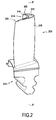
- FIG. 2 is visible, in perspective, an example of a rotor blade 10 of the second type, in particular a conventional hollow blade for a gas turbine. Cooling air (no shown) flows inside the blade from the bottom of the root 212 of the blade in the radial direction (vertical) towards the free end 214 of the blade (at the top in FIG. 2), then this cooling air escapes through an outlet to join the main gas flow.
- this cooling air circulates in an internal cooling passage 224 situated inside the blade 210 and which ends at the free end 214 of the blade at the level of through holes 215.
- the body of the blade is profiled so that it defines a lower surface wall 216 (on the left in all the figures) and an extrados wall 218 (on the right in all the figures).
- the intrados wall 216 has a generally concave shape and is the first face to the flow of hot gases, that is to say the gas pressure side, while the extrados wall 218 is convex and is presented by following the flow of hot gases, that is to say the suction side of the gas.
- intrados and extrados walls 218 are joined at the location of the leading edge 220 and at the location of the trailing edge 222 which extend radially between the free end 214 of the blade and the top of the foot 212 of dawn.
- the internal cooling passage 224 is delimited by a bottom wall 226 which extends over the entire end. free 214 of the blade, between the intrados wall 216 and the extrados wall 218, from the leading edge 220 to the trailing edge 222.
- the intrados and extrados walls 216, 218 form the rim 228 of a "bathtub" or open cavity 230 in the opposite direction to the internal cooling passage 224, radially outward (upwards in all figures).
- the through holes 215 through the entire thickness of the bottom wall 226, and communicate the open cavity 230 with the internal cooling passage 224.
- This rim 228 is formed of an extrados rim 2281 and a lower flange 2282 respectively radially outwardly extending (upwardly in all the figures) the extrados wall 218 and the the intrados wall 216, beyond the bottom wall 226 and up to the free end 214 of the blade.
- the flange 228 thus forms a thin wall along the profile of the blade which protects the free end 214 of the blade 210, in particular the bottom wall 226, from contact with the corresponding annular surface of the stator, for example the turbine casing.
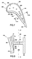
- inclined cooling channels 232 pass through the intrados wall 216 to connect the internal cooling passage 224 to the outside face of the intrados wall 216. below the outer face of the underside 2282.
- These cooling channels 232 are inclined so that they open towards the top of the intrados flange 2282 so as to cool as much as possible this vertex (arrow 33 in FIG. 6), along the pressure-side wall. 16, or more precisely along the outer face of the intrados flange 2282.
- the intrados wall 216 has a projecting end portion 234 whose external face is inclined with respect to the outside face of the intrados wall 216, the cooling channels 235 being disposed through this end portion 34.
- the intrados flange 2282 protrudes transversely outwardly at the location of the end portion 234 of the wall. 22, so that the outside face of the lower flange 2282 is inclined and forms an acute angle with the radial direction (vertical in Figure 8) or the axis XX 'of the outer face of the remainder of the wall. Inlet 216, this angle preferably being between 0 and 45 °, in particular between 10 and 35 °, advantageously between 15 and 30 °, and preferably of the order of 30 °.
- FIG. 9 shows another variant, according to which the intrados wall 216 no longer has a flange 2282.
- the top of the end portion 234 is orthogonal to the walls of the wall. and an extrados 218, in a direction parallel to the top of the extrados flange 2281, extending the outer surface of the bottom wall 226.
- the extrados rim 2281 has an inner face, turned towards the intrados wall 216 and facing the open cavity 230, extending in an inclined manner, forming an acute angle, ie less than 90 °, with the outer face of the bottom wall 226. In this case, the extrados edge 2281 is therefore wider at its top.
- this blade 210 of the second type (with “bath”) is hollow and includes an internal cooling passage 224, an open cavity 230 located at the free end 214 of the blade 210, and a bottom wall 226. extending over the entire end 214 of the blade, by separating said internal cooling passage 224 from the open cavity 230, said bottom wall 226 having, at the exit of the casting step, a rim base on which the 2281 flange is built by laser projection, layer after layer.
- FIGS. 11 to 13 forming partial sectional views for a lower flange 2282 such as that of FIG. 6.
- the outer profile of the rim 2282 has, as it appears in FIG. 12, substantially an inverted V shape or an inverted U shape with the inclined U branches. towards the top of the ledge 2282.
- flange 2282 is provided with an inverted U-shaped cross-sectional profile, with U-branches parallel to each other.
- the rim 2282 is machined directly into the blade 210 at the outlet of the foundry in the form recalled above. Then, if necessary, this flange 2282 may be coated with a deposit made by thermal spraying in order to reinforce its abrasion resistance properties.
- the free end 214 of the cast-off blade 210 has only been machined to provide a base 82 projecting from the upper surface of the bottom wall 226 of the free end 214 of dawn 210 at most a few millimeters, and this to initiate the beginning of the projecting shape of the rim 2282.
- an apparatus (not entirely shown) is used to make a laser projection.
- a first source of a first powder material 35 and a second source of a second powder material 45 are provided, said first source and said second source being connected to the projection nozzle 38.
- the optical head 34 and the nozzle 38 form a single assembly, that is to say that the optical head 34 and the projection nozzle 38 are integral with one another. other in the same projection assembly whose position is adjustable relative to the blade 210.
- the nozzle 38 may also be located separately beside the laser beam by being supported by a positioning device of its own to enable it to follow the movements of the focal point of the laser beam.
- the point-to-point material can be deposited in different configurations.
- the first layers are made only with the first material 35, then the last layers of the tip 84 come from the mixture of the first material 35 and the second material 45 which may consist of particles abrasive.
- step e) the first source (35) and the second source (45) of powder material are simultaneously activated so that the nozzle (38) projects a mixture of the first and second powder materials 35 and 45.
- the flange 2282 is formed of a base (82) surmounted by a point 84 (V-shaped or inverted U) whose composition varies from its free end 84a.
- the present invention also covers the case in which no flange base 82 is formed beforehand by the casting step of the blade 210, the realization of the entire height of the flange being made by construction as it has been described above, the rim base being reduced in this case (situation not shown) to a portion of the radially outer surface of the free end 214, which corresponds, in the case of the dawn of the second type to a portion of the outer surface of the bottom wall 226.
- FIG. 13 another possible procedure of the flange forming method 2282 according to the present invention is illustrated.
- the annular beads 83a made with the second powder material 45 form a coating 83 and the central areas filled with the first powder material 35 form the core 85 of the flange 2282.
- the first powder material 35 is identical to that constituting the blade and / or that the second powder material 45 is harder than the first material 35.
- a titanium alloy blade 210 there may be a titanium alloy blade 210, and the flange core 2282 also made of titanium alloy and a coating 83 in a hard and abrasive material, or a flange entirely of a hard and abrasive material.
- a hard and abrasive material particular choice is made among the hot oxidation resistant metals such as a MCrAlY type alloy (M being a metal selected from nickel, cobalt, iron or a mixture of these metals).
- each annular bead 83a is therefore carried out by continuously performing the laser projection deposition by performing a longitudinal displacement of the blade 210, this longitudinal direction extending between the leading edge 220 and the trailing edge 222 .
- the last layer of the flange 2282 will be formed by the same material as the cords 83a, in particular with the second material 45, harder than the first material 35.
- the flange 2282 is formed of a base 82 surmounted by an inverted U-shaped portion or tip 84 composed of a core 85 made of a first material 35, and a coating 83 covering the entire core 85 and made of a second material 45 harder than that of the core 85.
- the method proposed according to the present invention avoids on the one hand to perform a delicate machining and on the other hand, when using two different materials between the core and the surface, to perform a coating by a method of thermal projection that can not be done correctly in some geometric configurations.
- the core 85 is preferably a powdered metal material of the same composition as the blade 210, namely a titanium alloy or a nickel-based alloy, and for the coating 83, preferably hard and abrasive materials.
- the hot oxidation-resistant metals such as a MCrAlY type alloy (M being a metal chosen from nickel, cobalt, iron or a mixture of these metals) or an alloy based on cobalt, tungsten chromium such as Stellite (trademark).
- abrasive particles such as ceramics such as titanium dioxide (TiO 2), alumina (ALO 2), zirconia (ZrO 2) or a mixture made from one of they, or else SiC coated with AlN or Al2O3.
- cooling channels 232 connecting the internal cooling passage 224 and the outside face of the intrados wall 216 are pierced at even inside the flange 2282, the intrados wall 216 and any protruding part 234, and therefore after their construction by laser projection.
Abstract
Description
L'invention concerne un procédé de réalisation d'au moins un rebord situé à l'extrémité libre d'une aube, l'aube obtenue par ce procédé et la turbomachine équipée d'une telle aube.The invention relates to a method for producing at least one rim located at the free end of a blade, the blade obtained by this method and the turbine engine equipped with such a blade.
La présente invention porte aussi bien sur un premier type d'aubes dont l'extrémité libre est pourvue de plusieurs rebords, en général deux rebords, parallèles entre eux, formant chacun une léchette, que sur un deuxième type d'aubes creuses pourvues à leur extrémité libre d'une cavité ouverte ou « baignoire » bordée par ce rebord.The present invention also relates to a first type of blade whose free end is provided with a plurality of flanges, generally two flanges, parallel to each other, each forming a wiper, than on a second type of hollow blades provided to them. free end of an open cavity or "bath" bordered by this rim.
A titre illustratif, le document
Ces rebords ont pour fonction de limiter les surfaces en regard entre l'extrémité de l'aube et la surface annulaire correspondante du carter de turbine ou de compresseur, afin de protéger le corps de l'aube contre les dégâts causés par le contact éventuel avec un segment annulaire, tout en assurant une étanchéité entre le rotor et le stator.These edges have the function of limiting the facing surfaces between the end of the blade and the corresponding annular surface of the turbine housing or compressor, to protect the body of the blade against the damage caused by the possible contact with an annular segment, while ensuring a seal between the rotor and the stator.
Cette fonction d'étanchéité à l'extrémité des aubes est très importante puisque qu'elle conditionne les performances de la turbomachine, que ce soit pour l'efficacité d'un étage de turbine ou d'un compresseur équipé d'aubes mobiles. En effet, suivant les conditions de fonctionnement de la turbomachine, il existe des phénomènes d'instabilité ayant pour effet de faire diminuer le rendement de la turbomachine et/ou d'entraîner des surcharges mécaniques ou thermiques des aubes.This sealing function at the end of the blades is very important since it conditions the performance of the turbomachine, whether for the efficiency of a turbine stage or a compressor equipped with blades. Indeed, depending on the operating conditions of the turbomachine, there are instability phenomena having the effect of decreasing the efficiency of the turbomachine and / or causing mechanical or thermal overloads of the blades.
De plus, il existe un jeu entre le sommet des aubes et le stator. L'ensemble de cette situation conduit, en fonctionnement, à la présence de frottements entre les aubes et le stator, ce qui peut entraîner des détériorations au niveau des extrémités des aubes et/ou de la surface du stator, d'où une variation possible du jeu précité. En outre, d'une part le rotor et le stator qui lui est concentrique n'ont pas des formes strictement parfaitement circulaires et les variations de dilatation thermique différentielle ainsi que la déformation mécanique provenant des contraintes qui s'exercent modifient les dimensions de ces pièces.In addition, there is a game between the top of the blades and the stator. All of this situation leads, in operation, to the presence of friction between the blades and the stator, which can lead to damage at the ends of the blades and / or the surface of the stator, hence a possible variation of the aforementioned game. In addition, on the one hand the rotor and the stator which is concentric to it do not have strictly circular shapes and the variations of differential thermal expansion as well as the mechanical deformation resulting from the stresses which are exerted modify the dimensions of these parts. .
Pour diminuer ces frottements tout en garantissant l'étanchéité nécessaire, on utilise des garnitures d'étanchéité et d'usure formées de couronnes en matériaux « abradables » disposées sur les surfaces internes du stator en regard des aubes mobiles. Ceci signifie que les garnitures d'étanchéité du stator vont s'user ou s'abraser en fonction du passage des aubes jusqu'à s'accommoder avec les formes de ces dernières. Dans ce cas, les aubes sont munies de rebords formant des léchettes sur la périphérie radialement externe, qui sont destinés à coopérer avec les garnitures abradables, ces rebords présentant eux-même la forme d'éléments profilés, de formes variées, en matériau abrasif.To reduce this friction while ensuring the necessary seal, use seals and wear formed crowns of "abradable" materials disposed on the internal surfaces of the stator facing the blades. This means that stator seals will wear or abrade depending on the passage of the blades to accommodate the shapes of the latter. In this case, the blades are provided with rims forming wipers on the radially outer periphery, which are intended to cooperate with the abradable gaskets, these rims themselves having the form of profiled elements, of various shapes, of abrasive material.
Pour les aubes du deuxième type, le rebord ne se présente pas sous la forme de plusieurs léchettes mais d'un rebord, en général, continu délimitant une cavité ouverte à l'extrémité libre de l'aube, le rebord en question jouant cependant le même rôle.For the blades of the second type, the rim is not in the form of several wipers but a rim, generally continuous, delimiting an open cavity at the free end of the blade, the rim in question playing however the same role.
Habituellement, ces rebords sont fabriqués par fonderie simultanément avec le reste de l'aube, puis ils sont rectifiés par usinage pour leur donner leur forme définitive.Usually, these flanges are made by casting simultaneously with the rest of the blade, then they are ground by machining to give them their final shape.
En outre, pour éviter les détériorations, voir les destructions, des rebords, surtout lorsqu'on se trouve dans un compresseur ou une turbine haute pression, on peut revêtir ceux-ci par projection thermique (torche à plasma, à flamme oxygène à haute vitesse HVOF, ...) d'un dépôt abrasif par exemple de type alumine/bioxyde de titane ou carbure, par exemple sur une sous-couche d'alliage aluminium, de chrome et de nickel, pour en assurer l'adhérence.In addition, to avoid damage, see the destruction, rims, especially when in a compressor or a high pressure turbine, we can coat them by thermal spraying (plasma torch, oxygen flame high speed) HVOF, ...) of an abrasive deposit for example of alumina / titanium dioxide or carbide type, for example on an underlayer of aluminum alloy, chromium and nickel, to ensure adhesion.
Le dépôt par projection thermique est une technique lourde et qui requiert de respecter des angles relatifs de projection entre l'axe de la torche et les surfaces des pièces à revêtir, de manière à ce que l'impact des particules projetées soit le plus orthogonal possible par rapport à la surface à revêtir afin d'obtenir une qualité et une adhérence du dépôt satisfaisantes.Thermal spraying is a cumbersome technique that requires respect of relative projection angles between the axis of the torch and the surfaces of the parts to be coated, so that the impact of the projected particles is as orthogonal as possible. relative to the surface to be coated in order to obtain satisfactory quality and adherence of the deposit.
Par ailleurs, dans le cas du dépôt d'un revêtement, les gaz propulseurs ou plasmagènes utilisés pour la projection doivent pouvoir être aisément évacués sans toutefois «souffler» la poudre projetée en créant des turbulences.Moreover, in the case of the deposition of a coating, the propellant or plasma-generating gases used for the projection must be easily evacuated without, however, "blowing" the sprayed powder by creating turbulence.
La présente invention a pour but de surmonter ces inconvénients en proposant une solution qui permette de s'affranchir de la formation du ou des rebords par fonderie, ce qui simplifie les outillages de fonderie et évite le rebut de certaines pièces sortant de cette étape de fonderie.The object of the present invention is to overcome these disadvantages by proposing a solution that makes it possible to overcome the formation of the flange or rims by casting, which simplifies the foundry tools and avoids the rejection of certain pieces coming out of this foundry stage. .
Ce but de l'invention est atteint par procédé qui comporte les étapes suivantes :
- a) on fournit une aube présentant à son extrémité libre au moins une base de rebord,
- b) on fournit au moins une source d'un matériau en poudre et une buse de projection reliée à ladite source et apte à se déplacer par rapport à ladite aube,
- c) on fournit une source laser reliée à une tête optique apte à se déplacer par rapport à ladite aube pour focaliser le faisceau laser sur un point de la surface de ladite base de rebord,
- d) on règle la tête optique et la buse sur un même point de la surface du sommet de la base de rebord,
- e) on active la source laser et la source de matériau en poudre, ce par quoi on forme un bain de fusion localisé au niveau dudit point, dans lequel est injecté le matériau en poudre d'où il en résulte la formation d'une surépaisseur localisée ;
- f) on règle la tête optique et la buse sur un autre point de la surface du sommet de la base adjacent à ladite surépaisseur localisée et on retourne à l'étape e) jusqu'à la formation d'une couche sur sensiblement toute la largeur du sommet de la base ;
- g) on construit au moins une portion dudit rebord par le dépôt successif de couches sur le sommet de la base, chaque couche résultant de la réalisation des étapes d) à f).
- a) a blade having at its free end at least one flange base is provided,
- b) providing at least one source of a powder material and a projection nozzle connected to said source and able to move relative to said blade,
- c) providing a laser source connected to an optical head adapted to move relative to said blade to focus the laser beam on a point on the surface of said rim base,
- d) adjusting the optical head and the nozzle on the same point of the surface of the top of the rim base,
- e) activating the laser source and the source of powder material, thereby forming a melt located at said point, into which the powder material is injected, resulting in the formation of an excess thickness localized;
- f) adjusting the optical head and the nozzle on another point of the surface of the top of the base adjacent to said localized allowance and return to step e) until the formation of a layer over substantially the entire width from the top of the base;
- g) constructing at least a portion of said flange by the successive deposition of layers on the top of the base, each layer resulting from the realization of steps d) to f).
On comprend de ce qui précède qu'il est proposé de remplacer la formation du rebord par fonderie, ainsi que l'éventuel dépôt par projection thermique d'un revêtement abrasif sur la surface du rebord réalisé, par une construction complète de ce rebord, ou tout du moins une partie de la hauteur de la partie saillante que forme ce rebord, en ayant recours à une projection laser.It will be understood from the foregoing that it is proposed to replace the formation of the rim by casting, as well as the eventual thermal spraying deposit of an abrasive coating on the surface of the rim made, by a complete construction of this rim, or at least a part of the height of the projecting portion that forms this rim, using a laser projection.
La projection laser consiste à créer sur la pièce un bain de fusion très localisé, par action d'un faisceau laser pouvant être réglé de façon très précise, et à injecter dans ce bain de fusion de la poudre (métallique et/ou céramique), qui peut être abrasive. Ainsi, contrairement à la projection thermique, il n'est pas nécessaire de chauffer la poudre, sa trajectoire pouvant donc être dissociée de celle du faisceau laser.The laser projection consists in creating on the part a very localized melt, by the action of a laser beam which can be adjusted very precisely, and in injecting into this melt bath powder (metallic and / or ceramic), which can be abrasive. Thus, unlike thermal spraying, it is not necessary to heat the powder, its path can be dissociated from that of the laser beam.
Le faisceau laser se propage depuis sa source jusqu'à la cible par un chemin optique. Ce chemin optique est matérialisé soit pas une succession de miroirs qui reçoivent le faisceau et le renvoient dans une direction différente et de lentilles optiques et qui le font converger ou diverger ou le maintiennent parallèles, soit par une fibre optique.The laser beam propagates from its source to the target by an optical path. This optical path is materialized is not a succession of mirrors that receive the beam and send it in a different direction and optical lenses and converge or diverge or maintain parallel, or by an optical fiber.
Dans les deux cas, le chemin optique se termine par un système de lentilles appelées « tête optique » qui fait converger le faisceau en un point plus ou moins éloigné. Le dispositif à projection laser permet une très grande souplesse d'utilisation dès lors qu'il n'y a pas d'obstacle entre la tête optique et le point d'impact visé par le faisceau sur la pièce. En effet, dans le cas d'une projection thermique, il est nécessaire que la poudre arrive avec une direction d'impact normale à la surface à revêtir. De façon tout à fait différente, avec le procédé proposé selon la présente invention, la projection laser ne nécessitant que le remplissage du bain de fusion, la poudre peut être envoyée avec des trajectoires tout à fait variables par rapport à la surface de réception.In both cases, the optical path ends with a system of lenses called "optical head" which converges the beam at a more or less distant point. The laser projection device allows a very great flexibility of use when there is no obstacle between the optical head and the point of impact targeted by the beam on the workpiece. Indeed, in the case of thermal spraying, it is necessary for the powder to arrive with a direction of impact normal to the surface to be coated. In a completely different way, with the method proposed according to the present invention, since the laser projection requires only the filling of the melt, the powder can be sent with quite variable paths with respect to the receiving surface.
La poudre métallique est distribuée par un distributeur de poudre. Elle chemine dans un tube dont l'extrémité comporte une buse qui dirige la poudre vers le bain de fusion créé par le faisceau laser. Ce tube peut être souple et guidé par un bras rigide support ou par un robot ou tout autre dispositif de positionnement, ou bien il peut être rigide et orienté vers la zone à revêtir de la pièce.The metal powder is dispensed by a powder dispenser. It travels in a tube whose end includes a nozzle that directs the powder to the melt created by the laser beam. This tube can be flexible and guided by a rigid support arm or by a robot or other positioning device, or it can be rigid and oriented towards the area to be coated part.
On peut relever d'autres avantages du procédé de projection laser.There are other advantages of the laser projection method.
Dans le cas de la projection thermique, la buse transmettant les gaz chauds doit être proche de la surface à revêtir, tandis que dans le cas de la projection laser, la tête optique peut être relativement éloignée de cette surface. Dans le cas de la projection thermique, la poudre doit être chauffée de sorte qu'elle doit présenter une trajectoire commune avec les gaz chauds, ce qui n'est pas le cas avec une projection laser dans laquelle la trajectoire de la poudre peut être dissociée de celle du faisceau laser.In the case of thermal spraying, the nozzle conveying the hot gases must be close to the surface to be coated, whereas in the case of laser projection, the optical head may be relatively far from this surface. In the case of thermal spraying, the powder must be heated so that it must have a common trajectory with the hot gases, which is not the case with a laser projection in which the trajectory of the powder can be dissociated. of that of the laser beam.
En outre, dans le cas de la projection thermique, on réalise un procédé de revêtement continu alors que dans le cas d'une projection laser, compte tenu de la souplesse de commande du faisceau laser, il est possible de réaliser la projection de façon continue ou de façon séquentielle, par un simple arrêt du faisceau laser.In addition, in the case of thermal spraying, a continuous coating process is carried out whereas in the case of a laser projection, given the control flexibility of the laser beam, it is possible to carry out the projection continuously. or sequentially, by simply stopping the laser beam.
En outre, on comprend que la solution conforme à la présente invention évite d'avoir à usiner le rebord issu de fonderie, qui est un emplacement relativement délicat à réaliser. En effet, grâce au procédé conforme à la présente invention, on construit simultanément, couche par couche, le rebord, ainsi, le cas échéant, que son revêtement avec un matériau suffisamment abrasif.In addition, it is understood that the solution according to the present invention avoids having to machine the rim from foundry, which is a relatively difficult location to achieve. Indeed, thanks to the process according to the present invention, is built simultaneously layer by layer, the rim, and if necessary, that its coating with a sufficiently abrasive material.
À cet égard, il faut noter que ce procédé peut réaliser la construction du rebord sur toute sa hauteur (dans ce cas, la base de rebord est simplement un emplacement de l'extrémité libre de l'aube) ou bien uniquement la construction du rebord sur une partie de sa hauteur formant son extrémité ou sa pointe (dans ce cas, la base de rebord est un rebord de faible hauteur, formant un moignon à l'extrémité libre de l'aube, et qui provient de l'étape de fonderie et de l'éventuelle étape de rectification par usinage).In this regard, it should be noted that this method can realize the construction of the rim over its entire height (in this case, the rim base is simply a location of the free end of the blade) or only the construction of the rim on a part of its height forming its end or tip (in this case, the rim base is a low rim, forming a stub at the free end of the blade, and which comes from the foundry step and the possible grinding step by machining).
Dans l'étape e) l'activation de la source laser et de la source de matériau en poudre est effectuée successivement ou quasi simultanément afin que le bain de fusion localisé soit présent à l'emplacement sur lequel est dirigé le faisceau laser lorsque la poudre, qui arrive sur ce même emplacement, vient impacter cette surface.In step e) the activation of the laser source and the source of powder material is carried out successively or almost simultaneously so that the localized melt is present at the location on which the laser beam is directed when the powder , which arrives on this same site, impacts this surface.
En outre, du fait de la très grande souplesse d'utilisation de cette technique de projection laser, ce ou ces rebords peuvent être réalisés dans un matériau choisi différent de celui de l'aube, en tout ou partie.In addition, because of the great flexibility of use of this laser projection technique, this or these flanges can be made of a selected material different from that of the blade, in whole or in part.
De plus, on comprend qu'on s'affranchit de la réalisation éventuelle d'un dépôt de revêtement par projection thermique afin de pouvoir tout de même réaliser des rebords qui ne soient pas endommagés par leur contact avec le stator et l'éventuelle couronne d'abradable.In addition, it is understood that it avoids the possible realization of a thermal spray coating deposit in order to still achieve edges that are not damaged by their contact with the stator and the possible crown of 'abradable.
De préférence, on réalise les étapes d) à f) tant que toute la surface du sommet de la base de rebord n'est pas revêtue d'une couche et pendant l'étape g) on construit le rebord par le dépôt successif de couches sur toute la surface du sommet de la base de rebord, chaque couche résultant de la réalisation des étapes d) à f). On peut prévoir de déposer successivement des couches de plus en plus étroites en direction transversale à la paroi d'extrados et/ou d'intrados.Preferably, steps d) to f) are carried out as long as the entire surface of the top of the rim base is not coated with a layer and during step g) the rim is constructed by the successive deposition of layers. over the entire surface of the top of the rim base, each layer resulting from the realization of steps d) to f). It can be provided to successively deposit increasingly narrow layers in the transverse direction to the extrados wall and / or intrados.
En effet, il est préférable de construire le rebord strate par strate, en réalisant en premier lieu une nouvelle couche sur toute la surface du sommet de la base de rebord avant de continuer cette construction radialement plus à l'extérieur.Indeed, it is better to build the stratum stratum by stratum, realizing in the first place a new layer on all the top surface of the rim base before continuing this construction radially further out.
Néanmoins, on peut concevoir d'autres méthodes de construction, parmi lesquels la construction couche par couche d'un secteur du rebord avant de poursuivre la construction d'un autre secteur du rebord, ou encore, au moyen de plusieurs têtes optiques et de plusieurs buses, la fabrication simultanée de plusieurs secteurs du rebord.Nevertheless, other methods of construction can be devised, including the layer-by-layer construction of one sector of the rim before continuing the construction of another sector of the rim, or else by means of several optical heads and several nozzles, the simultaneous manufacture of several sectors of the rim.
De préférence, pendant l'étape f), on parcourt la surface du sommet de la base de rebord selon une direction transversale à la paroi d'intrados et/ou d'extrados avant de se décaler en direction longitudinale qui s'étend entre le bord d'attaque et le bord de fuite.Preferably, during step f), the surface of the top of the rim base is traversed in a direction transverse to the intrados and / or extrados wall before shifting in the longitudinal direction which extends between the leading edge and the trailing edge.
Dans ce cas, on construit chaque couche ligne par ligne en déplaçant, le long de cette ligne, le réglage de la tête optique et de la buse (ou en déplaçant l'extrémité de l'aube par rapport à l'appareillage de projection laser) parallèlement à la direction transversale à la paroi d'intrados et/ou d'intrados, avant d'effectuer un décalage en direction longitudinale de l'extrémité de l'aube et de commencer une nouvelle ligne jusqu'à la fin de la réalisation d'une couche.In this case, one builds each layer line by line by moving, along this line, the adjustment of the optical head and the nozzle (or moving the end of the blade with respect to the laser projection apparatus ) parallel to the direction transverse to the intrados and / or intrados wall, before shifting in the longitudinal direction of the end of the blade and start a new line until the end of the realization a layer.
Bien entendu, on peut concevoir d'autres trajectoires de déplacement pour construire chaque couche, par exemple en fabricant à la suite les uns des autres, des cordons de matière qui seront décalés légèrement en direction transversale les uns par rapport aux autres.Of course, it is possible to design other displacement paths for constructing each layer, for example by manufacturing one after the other, strings of material which will be shifted slightly in the transverse direction relative to each other.
Selon une autre disposition préférentielle, au cours de l'étape f) la source laser et la source de matériau en poudre restent activées.According to another preferred arrangement, during step f) the laser source and the source of powder material remain activated.
De cette façon, on peut réaliser en continu la construction du rebord par formation d'îlots successifs de matière, soit pour la formation complète du rebord, soit par des séquences correspondant chacune à la fabrication d'une partie (par exemple une couche complète du rebord). Alternativement ou en combinaison avec ces différentes possibilités, on peut également, notamment dans les zones les plus délicates à atteindre et/ou les plus fines au niveau des dimensions, réaliser un dépôt de matière point après point en désactivant la source laser et la source de matériau au cours de l'étape f).In this way, the construction of the rim can be carried out continuously by forming successive islands of material, either for the complete formation of the rim, or by sequences each corresponding to the manufacture of a part (for example a complete layer of flange). Alternatively or in combination with these different possibilities, it is also possible, particularly in the most delicate areas to reach and / or the finest in terms of dimensions, to achieve a point-by-point material deposition by deactivating the laser source and the source of the material. material during step f).
L'invention concerne aussi une aube de rotor d'un moteur à turbine à gaz comportant au moins un rebord situé à l'extrémité libre, où le rebord est obtenu par le procédé conforme à la présente invention présenté précédemment.The invention also relates to a rotor blade of a gas turbine engine comprising at least one rim located at the free end, where the rim is obtained by the method according to the present invention presented above.
Comme il ressort de l'exposé ci-dessus du procédé conforme à l'invention, il faut comprendre que ce rebord est fabriqué entièrement (sur toute sa hauteur) ou seulement en partie, à savoir sa partie d'extrémité constituant le sommet, par ce procédé.As is apparent from the above description of the process according to the invention, it should be understood that this flange is manufactured entirely (over its entire height) or only partly, namely its end portion constituting the vertex, by this process.
Dans le dernier cas, la partie radialement intérieure du rebord est formée d'une base préalablement réalisée par fonderie avec le reste de l'aube.In the latter case, the radially inner portion of the flange is formed of a base previously made by casting with the rest of the blade.
En particulier, cette aube fait partie du rotor d'un compresseur basse pression ou haute pression ou d'une turbine basse pression ou haute pression d'une turbomachine.In particular, this blade is part of the rotor of a low pressure or high pressure compressor or a low pressure or high pressure turbine of a turbomachine.
Egalement, la présente invention porte sur une turbomachine comprenant une aube de rotor du type cité précédemment.Also, the present invention relates to a turbomachine comprising a rotor blade of the type mentioned above.
D'autres avantages et caractéristiques de l'invention ressortiront à la lecture de la description suivante faite à titre d'exemple et en référence aux dessins annexés dans lesquels :
- la figure 1 est une vue en perspective d'une aube du premier type;
- la figure 2 est une vue en perspective d'une aube du deuxième type ;
- la figure 3 montre en perspective, de manière agrandie, l'extrémité libre de l'aube de la figure 2,
- la figure 4 est une vue simplifiée selon la direction IV de la figure 3, de l'extrémité libre de l'aube.
- la figure 5 est une vue analogue à celle de la figure 3, après que le bord de fuite de l'aube ait été retiré par une coupe longitudinale,
- la figure 6 est une vue en coupe longitudinale selon la direction VI-VI de la figure 4 ou de la figure 5, et
- la figure 7 est une vue analogue à celle de la figure 4 montrant une variante de réalisation ;
- la figure 8 est une vue analogue à celle de la figure 6 pour la variante de réalisation de la figure 7 ;
- la figure 9 montre une vue analogue à celle de la figure 8 pour une aube conforme à une autre variante de réalisation ;
- la figure 10 est une vue d'extrémité simplifiée similaire à celle de la figure 4 pour une aube combinant différentes formes de rebord pour l'extrémité libre de l'aube ;
- les figures 11 et 12 représentent une vue en coupe axiale schématique partielle et agrandie de l'extrémité libre d'une aube montrant l'évolution de la section transversale et du profil du rebord lors d'une mise en oeuvre du procédé de fabrication conforme à la présente l'invention, et
- la figure 13 est une vue analogue à celle de la figure 11 pour une variante de réalisation du procédé conforme à la présente l'invention.
- Figure 1 is a perspective view of a blade of the first type;
- Figure 2 is a perspective view of a blade of the second type;
- FIG. 3 shows in perspective, in an enlarged manner, the free end of the blade of FIG. 2,
- Figure 4 is a simplified view along the direction IV of Figure 3, the free end of the blade.
- FIG. 5 is a view similar to that of FIG. 3, after the trailing edge of the blade has been removed by a longitudinal section,
- FIG. 6 is a view in longitudinal section along the direction VI-VI of FIG. 4 or FIG. 5, and
- Figure 7 is a view similar to that of Figure 4 showing an alternative embodiment;
- Figure 8 is a view similar to that of Figure 6 for the embodiment of Figure 7;
- Figure 9 shows a view similar to that of Figure 8 for a blade according to another embodiment;
- Figure 10 is a simplified end view similar to that of Figure 4 for a blade combining different flange shapes for the free end of the blade;
- FIGS. 11 and 12 show a fragmentary and enlarged schematic axial sectional view of the free end of a blade showing the evolution of the cross-section and the profile of the flange during an implementation of the manufacturing method according to FIG. the present invention, and
- Figure 13 is a view similar to that of Figure 11 for an alternative embodiment of the method according to the present invention.
La figure 1 montre une aube 110 de turbomachine du premier type qui comporte un pied d'aube 112 à son extrémité interne et une extrémité libre 114 formant un talon à son extrémité périphérique externe. Cette aube 110 s'étend le long d'une direction radiale le long d'un axe d'aube X-X' favorisant l'écoulement axial, cet axe X-X' étant perpendiculaire à l'axe du rotor sur lequel est montée cette aube 110. Sur sa longueur, l'aube 110 présente un profilé avec une paroi d'intrados 116 et une paroi extrados 118.FIG. 1 shows a
Au niveau de son extrémité libre 114, l'aube 110 présente deux léchettes ou rebords 128, respectivement 1281 et 1282, qui s'étendent transversalement par rapport aux parois d'intrados 116 et d'extrados 118 selon une direction sensiblement rectiligne en faisant saillie radialement depuis l'extrémité libre 114. La hauteur des rebords 1281 et 1282 peut aussi bien être identique entre les deux rebords et tout le long de ces rebords, ou bien présenter une hauteur variable, notamment une hauteur supérieure du côté de la paroi d'extrados de manière à former un effet «dents de scie » d'une aube à l'autre. Dans tous les cas, la variation de la hauteur reste faible et ne dépasse par exemple pas 0,2 mm pour éviter une usure du rebord 128.At its
Ainsi, cette aube 110 du premier type comprend plusieurs rebords 128 (en particulier deux rebords 1281 et 1282) s'étendant entre le bord d'attaque 20 et le bord de fuite 22 et parallèlement entre eux, en formant des léchettes s'étendant en direction longitudinale et qui sont séparées les unes des autres.Thus, this
Sur la figure 2 est visible, en perspective, un exemple d'une aube 10 de rotor du deuxième type, en particulier une aube creuse conventionnelle pour une turbine à gaz. De l'air de refroidissement (non représenté) s'écoule à l'intérieur de l'aube depuis le bas du pied 212 de l'aube dans la direction radiale (verticale) vers l'extrémité libre 214 de l'aube (en haut sur la figure 2), puis cet air de refroidissement s'échappe par une sortie pour rejoindre le flux de gaz principal.In Figure 2 is visible, in perspective, an example of a rotor blade 10 of the second type, in particular a conventional hollow blade for a gas turbine. Cooling air (no shown) flows inside the blade from the bottom of the
En particulier, comme il ressort des figures 5 à 10, cet air de refroidissement circule dans un passage de refroidissement interne 224 situé à l'intérieur de l'aube 210 et qui aboutit à l'extrémité libre 214 de l'aube au niveau de perçages débouchants 215.In particular, as is apparent from FIGS. 5 to 10, this cooling air circulates in an
Le corps de l'aube est profilé de sorte qu'il définit une paroi d'intrados 216 (à gauche sur toutes les figures) et une paroi d'extrados 218 (à droite sur toutes les figures). La paroi d'intrados 216 présente une forme générale concave et se présente la première face au flux de gaz chauds, c'est-à-dire du côté pression des gaz, tandis que la paroi d'extrados 218 est convexe et se présente par la suite au flux de gaz chauds, c'est-à-dire du côté aspiration des gaz.The body of the blade is profiled so that it defines a lower surface wall 216 (on the left in all the figures) and an extrados wall 218 (on the right in all the figures). The
Les parois d'intrados 216 et d'extrados 218 se rejoignent à l'emplacement du bord d'attaque 220 et à l'emplacement du bord de fuite 222 qui s'étendent radialement entre l'extrémité libre 214 de l'aube et le haut du pied 212 de l'aube.The intrados and
Comme il ressort des vues agrandies des figures 3, 5 et 6, au niveau de l'extrémité libre 214 de l'aube, le passage de refroidissement interne 224 est délimité par une paroi de fond 226 qui s'étend sur toute l'extrémité libre 214 de l'aube, entre la paroi d'intrados 216 et la paroi d'extrados 218, depuis le bord d'attaque 220 jusqu'au bord de fuite 222.As can be seen from the enlarged views of FIGS. 3, 5 and 6, at the
Au niveau de l'extrémité libre 214 de l'aube, les parois d'intrados et d'extrados 216, 218 forment le rebord 228 d'une « baignoire » ou cavité ouverte 230 dans la direction opposée au passage de refroidissement interne 224, soit radialement vers l'extérieur (vers le haut sur toutes les figures).At the
Les perçages débouchants 215 traversant toute l'épaisseur de la paroi de fond 226, et font communiquer la cavité ouverte 230 avec le passage de refroidissement interne 224.The through
Ce rebord 228 est formé d'un rebord d'extrados 2281 et d'un rebord d'intrados 2282 prolongeant respectivement radialement vers l'extérieur (vers le haut sur toutes les figures) la paroi d'extrados 218 et la paroi d'intrados 216, au-delà de la paroi de fond 226 et jusqu'à l'extrémité libre 214 de l'aube.This
Le rebord 228 forme donc une paroi mince le long du profil de l'aube qui protège l'extrémité libre 214 de l'aube 210, en particulier la paroi de fond 226, du contact avec la surface annulaire correspondante du stator, par exemple le carter de turbine.The
Comme on peut le voir plus précisément sur la vue en coupe de la figure 6, des canaux de refroidissement 232 inclinés traversent la paroi d'intrados 216 pour relier le passage de refroidissement interne 224 à la face extérieure de la paroi d'intrados 216, en dessous de la face extérieure du rebord d'intrados 2282.As can be seen more precisely in the sectional view of FIG. 6, inclined cooling
Ces canaux de refroidissement 232 sont inclinés de façon à ce qu'ils débouchent en direction du sommet du rebord d'intrados 2282 afin de refroidir autant que possible ce sommet (flèche 33 sur la figure 6), le long de la paroi d'intrados 16, ou plus précisément le long de la face extérieure du rebord d'intrados 2282.These cooling
Selon une variante visible sur les figures 7 et 8, la paroi d'intrados 216 présente une portion d'extrémité 234 en saillie dont la face extérieure est inclinée par rapport à la face extérieure de la paroi d'intrados 216, les canaux de refroidissement 235 étant disposés à travers cette portion d'extrémité 34. Selon cette variante des figures 7 et 8, le rebord d'intrados 2282 est en saillie transversalement vers l'extérieur à l'emplacement de la portion d'extrémité 234 de la paroi d'intrados 216, de sorte que la face extérieure du rebord d'intrados 2282 est inclinée et forme un angle aigu avec la direction radiale (verticale sur la figure 8) ou l'axe X-X' de la face extérieure du reste de la paroi d'intrados 216, cet angle étant de préférence compris entre 0 et 45°, en particulier entre 10 et 35°, avantageusement entre 15 et 30°, et de préférence de l'ordre de 30°.According to a variant visible in FIGS. 7 and 8, the
On se reportera maintenant à la figure 9 qui représente une autre variante, selon laquelle la paroi d'intrados 216 ne comporte plus de rebord d'intrados 2282. Selon cette variante, le sommet de la portion d'extrémité 234 est orthogonale aux parois d'intrados 216 et d'extrados 218, selon une direction parallèle au sommet du rebord d'extrados 2281, en prolongeant la surface extérieure de la paroi de fond 226.Reference is now made to FIG. 9, which shows another variant, according to which the
En outre, le rebord d'extrados 2281 présente une face intérieure, tournée en direction de la paroi d'intrados 216 et faisant face à la cavité ouverte 230, s'étendant de façon inclinée, en formant un angle aigu, autrement dit inférieur à 90°, avec la face extérieure de la paroi de fond 226. Dans ce cas, le rebord d'extrados 2281 est donc plus large au niveau de son sommet.In addition, the
Il faut noter que les différentes variantes illustrées et décrites précédemment peuvent se combiner entre elles.It should be noted that the various variants illustrated and described above can be combined with each other.
Ainsi, par exemple, la figure 10 illustre l'extrémité libre 214 d'une aube du deuxième type 210 qui présente plusieurs configurations de rebord entre son bord d'attaque 220 et son bord de fuite 222 :
- à l'avant de l'aube, en aval du bord d'attaque 220, on retrouve la conformation de la figure 9 avec une
portion d'extrémité 234 en saillie transversale côté paroi d'intrados 216, sans rebord d'intrados et avec un rebord d'extrados 2281 élargi à son sommet; - à l'arrière de l'aube, en amont du bord de fuite 22, on retrouve la disposition de la figure 8 avec, du côté de la paroi d'intrados 216,
une portion d'extrémité 234 en saillie transversale comprenant le rebord d'intrados 2282 élargi à son sommet, et du côté de la paroi d'extrados 218, un rebord d'extrados 2281 non élargi à son sommet.
- at the front of the blade, downstream of the
leading edge 220, there is the conformation of FIG. 9 with anend portion 234 projecting transversely on theinside wall side 216, without a lower lip and with anextrados rim 2281 enlarged at its top; - at the rear of the blade, upstream of the trailing edge 22, there is the arrangement of Figure 8 with, on the side of the
intrados wall 216, anend portion 234 projecting transverse including theflange intrados 2282 widened at its top, and the side of theextrados wall 218, anextrados rim 2281 not widened at its top.
Ainsi, cette aube 210 du deuxième type (avec « baignoire ») est creuse et comprend un passage de refroidissement interne 224, une cavité 230 ouverte située à l'extrémité libre 214 de l'aube 210, et une paroi de fond 226 s'étendant sur toute l'extrémité 214 de l'aube, en séparant ledit passage de refroidissement interne 224 de la cavité ouverte 230, ladite paroi de fond 226 présentant, à la sortie de l'étape de fonderie, une base de rebord sur laquelle le rebord 2281 est construit par projection laser, couche après couche.Thus, this
Dans le cas des aubes du premier type et du deuxième type, et du procédé de réalisation du rebord conforme à la présente invention, l'une ou les deux dispositions suivantes est (sont) de préférence adoptée(s) :
- le rebord 128
ou 228 s'étend entre le bord d'attaque (120 ou 220) et le bord de fuite (122 ou 222) ; - le rebord 128
ou 228 s'étend le long d'au moins la paroi d'extrados (118 ou 218).
- the
flange - the
flange
À titre d'exemple, un mode de réalisation du procédé conforme à la présente invention va maintenant être décrit en relation avec les figures 11 à 13 formant des vues partielles en coupe pour un rebord d'intrados 2282 tel que celui de la figure 6.By way of example, an embodiment of the method according to the present invention will now be described in relation with FIGS. 11 to 13 forming partial sectional views for a
En section transversale par rapport aux parois d'intrados 216 et d'extrados 218, le profil extérieur du rebord 2282 présente, comme il apparaît sur la figure 12, sensiblement une forme de V inversé ou de U inversé avec les branches du U inclinées en direction du sommet du rebord 2282.In cross-section with respect to the intrados and
En alternative, comme il apparaît sur la figure 13, le rebord 2282 est prévu avec un profil en section transversale en forme de U inversé, avec les branches du U parallèles entre elles.Alternatively, as shown in Fig. 13,
Cependant, comme il a déjà été exposé précédemment, selon les techniques de l'art antérieur, le rebord 2282 est usiné directement dans l'aube 210 en sortie de fonderie selon la forme rappelée ci-dessus. Ensuite, on peut, le cas échéant, revêtir ce rebord 2282 par un dépôt réalisé par projection thermique afin de renforcer ses propriétés de résistance à l'abrasion.However, as already explained above, according to the techniques of the prior art, the
Au contraire, selon la présente invention, l'extrémité libre 214 de l'aube 210 issue de fonderie a seulement été usinée afin de réaliser une base 82 faisant saillie de la surface supérieure de la paroi de fond 226 de l'extrémité libre 214 de l'aube 210 au plus de quelques millimètres, et ceci pour amorcer le début de la forme en saillie du rebord 2282.In contrast, according to the present invention, the
Ensuite, on utilise, pour la fabrication du reste du rebord 2282, à savoir son extrémité ou pointe 14, un appareillage (non entièrement représenté) permettant de réaliser une projection laser.Then, for the manufacture of the remainder of the
Cet appareillage comporte les parties suivantes:
- un système permettant de saisir l'aube 210 et de la déplacer, notamment en rotation et en translation;
- une source laser (CO2 ou YAG) 30 avec un système de transmission du faisceau
laser 32 par réflexion sur des miroirs ou par une fibre optique, jusqu'à une tête optique 34 ; - la tête optique 34 présente une distance focale correspondant à la distance entre cette dernière et la surface à revêtir, cette tête optique 34 est solidaire d'un dispositif de positionnement capable de la placer de façon à ce que le point focal du faisceau puisse balayer tous les points d'une section droite de la surface à revêtir, ou du volume à construire ;
- au moins une source d'un premier matériau en poudre 35 comportant un distributeur et un doseur de poudre ainsi que le tuyau d'alimentation 36 de cette poudre jusqu'à la buse 38.
- a system for grasping the
blade 210 and moving it, in particular in rotation and in translation; - a laser source (CO2 or YAG) 30 with a transmission system of the
laser beam 32 by reflection on mirrors or by an optical fiber, up to anoptical head 34; - the
optical head 34 has a focal length corresponding to the distance between the latter and the surface to be coated, thisoptical head 34 is integral with a positioning device capable of placing it so that the focal point of the beam can scan all the points of a cross section of the surface to be coated, or of the volume to build; - at least one source of a first powder material comprising a dispenser and a powder dispenser and the
feed pipe 36 of this powder to thenozzle 38.
Dans le cas représenté, on dispose également d'une source d'un deuxième matériau en poudre 45 reliée à la buse 38 par un tuyau d'alimentation 46 correspondant.In the case shown, there is also a source of a
Ainsi, on comprend que de préférence, pendant l'étape b) on fournit une première source d'un premier matériau en poudre 35 et une deuxième source d'un deuxième matériau en poudre 45, ladite première source et ladite deuxième source étant reliées à la buse de projection 38.Thus, it is understood that, during step b), a first source of a
Dans le cas représenté schématiquement sur les figures 11 à 13, la tête optique 34 et la buse 38 forment un même ensemble, c'est-à-dire que la tête optique 34 et la buse 38 de projection sont solidaires l'une de l'autre dans un même ensemble de projection dont la position est réglable par rapport à l'aube 210.In the case shown diagrammatically in FIGS. 11 to 13, the
Cependant la buse 38 peut également être située séparément à côté du faisceau laser en étant supportée par un dispositif de positionnement qui lui est propre afin de lui permettre de suivre les mouvements du point de focalisation du faisceau laser.However, the
En relation avec les figures 11 à 13, il faut comprendre que la construction de la pointe 84 du rebord 2282 s'effectue couche par couche jusqu'à l'extrémité libre de la pointe 84.With reference to FIGS. 11 to 13, it should be understood that the construction of the
Pour chaque couche devant être formée, on peut déposer la matière point à point selon différentes configurations.For each layer to be formed, the point-to-point material can be deposited in different configurations.
En particulier, comme il est illustré sur la figure 11, on peut prévoir de réaliser côte à côte des lanières de matières orientées selon la direction transversale aux parois d'extrados et d'intrados 216, en déplaçant, pour chaque lanière, la tête optique 34 et l'aube 210 l'une par rapport à l'autre (flèche 86 de la figure 11). Ensuite, on déplace la tête optique 34 et l'aube 210 l'une par rapport à l'autre en direction longitudinale pour débuter une autre lanière, et ceci jusqu'à la fin de la formation de la nouvelle couche de matière.In particular, as illustrated in FIG. 11, it is possible to produce, side by side, strips of materials oriented in the direction transverse to the extrados and
Ensuite on reprend les étapes pour une nouvelle couche de matière plus étroite, jusqu'à l'extrémité libre 84a de la pointe 84 (figure 12).Then the steps are taken for a new narrower material layer, up to the
Dans le cas illustré sur les figures 11 et 12, les premières couches sont réalisées uniquement avec le premier matériau 35, puis les dernières couches de la pointe 84 proviennent du mélange ente le premier matériau 35 et le deuxième matériau 45 qui peut être constitué de particules abrasives.In the case illustrated in FIGS. 11 and 12, the first layers are made only with the
Dans ce cas, pendant l'étape e) on active simultanément la première source (35) et la deuxième source (45) de matériau en poudre de sorte que la buse (38) projette un mélange des premier et deuxième matériaux en poudre 35 et 45.In this case, during step e) the first source (35) and the second source (45) of powder material are simultaneously activated so that the nozzle (38) projects a mixture of the first and
Alternativement, on peut prévoir une composition de matière de la pointe 84 variant progressivement, avec de plus en plus de deuxième matériau 45 mélangé au premier matériau 35 au fur et à mesure que l'on se rapproche de l'extrémité libre 84a de la pointe du rebord 2282.Alternatively, it is possible to provide a material composition of the
Dans ce cas, on comprend qu'en général, le rebord 2282 est formé d'une base (82) surmontée d'une pointe 84 (en forme de V ou de U inversé) dont la composition varie depuis son extrémité libre 84a.In this case, it is understood that in general, the
Il faut noter que la présente invention recouvre également le cas dans lequel aucune base de rebord 82 n'est formée au préalable par l'étape de fonderie de l'aube 210, la réalisation de toute la hauteur du rebord étant effectuée par construction comme il a été décrit ci-dessus, la base de rebord se réduisant dans ce cas (situation non représentée) à une portion de la surface radialement extérieure de l'extrémité libre 214, ce qui correspond, dans le cas de l'aube du deuxième type à une portion de la surface extérieure de la paroi de fond 226.It should be noted that the present invention also covers the case in which no
Egalement, sur la figure 13, on illustre une autre procédure possible du procédé de formation du rebord 2282 selon la présente invention.Also, in Fig. 13, another possible procedure of the
Ici, on réalise en premier lieu par fusion du deuxième matériau en poudre 45 deux cordons annulaires 83a le long des deux bords longitudinaux du sommet de la base 82 de rebord (ou de la couche réalisée précédemment), puis on remplit par apport du premier matériau en poudre 35 dans le bain de fusion localisé engendré par le faisceau laser, l'espace en forme de cuvette formé entre ces deux cordons annulaires 83a, ce qui permet de construire une zone centrale qui va constituer au final l'âme 85 du rebord 2282.Here, firstly by merging the
De cette façon, couche par couche, les cordons annulaires 83a réalisés avec le deuxième matériau en poudre 45 forment un revêtement 83 et les zones centrales remplies du premier matériau en poudre 35 forment l'âme 85 du rebord 2282.In this way, layer by layer, the
De préférence, on s'arrange pour que le premier matériau en poudre 35 est identique à celui constituant l'aube et/ ou que le deuxième matériau en poudre 45 est plus dur que le premier matériau 35.Preferably, it is arranged that the
De cette façon, on obtiendra un revêtement 83 plus dur que l'âme 85 du rebord 2282.In this way, a
Par exemple, on peut avoir une aube 210 en alliage de titane, et l'âme du rebord 2282 également en alliage de titane et un revêtement 83 dans un matériau dur et abrasif, ou bien un rebord entièrement en un matériau dur et abrasif. Comme matériau dur et abrasif, on choisit notamment parmi les métaux résistant à l'oxydation à chaud tels qu'un alliage de type MCrAlY (M étant un métal choisi parmi le nickel, le cobalt, le fer ou un mélange de ces métaux).For example, there may be a
On comprend donc que selon le procédé de la figure 13, chaque couche (sauf la dernière) formant le rebord 2282 résulte des deux sous-étapes suivantes :
- on forme à la surface de la base de rebord 82 deux cordons annulaires 83a avec le deuxième matériau en poudre 45 (en variante on peut prévoir un mélange dudit premier matériau 35 et dudit deuxième matériau 45) par le fait qu'au cours de l'étape précédente, la tête optique 34 et la buse 38 sont décalées légèrement en direction longitudinale qui s'étend entre le bord d'attaque 220 et le bord de fuite 222 par rapport à la surépaisseur localisée obtenue précédemment, et
- on remplit la
zone 85 située entre les deux cordons 83a avec le premier matériau enpoudre 35.
- two
annular beads 83a are formed on the surface of theflange base 82 with the second powder material 45 (alternatively a mixture of saidfirst material 35 and said second material 45) can be provided by the fact that during preceding step, theoptical head 34 and thenozzle 38 are offset slightly in the longitudinal direction which extends between theleading edge 220 and the trailingedge 222 with respect to the localized excess thickness obtained previously, and -
zone 85 between the twocords 83a is filled with thefirst powder material 35.
La réalisation de chaque cordon annulaire 83a s'effectue donc en réalisant en continu le dépôt par projection laser en effectuant un déplacement longitudinal de l'aube 210, cette direction longitudinale s'étendant entre le bord d'attaque 220 et le bord de fuite 222.The realization of each
Le remplissage de la cuvette délimitée entre les deux cordons 83a avec le premier matériau en poudre 35 peut être réalisé selon plusieurs possibilités parmi lesquelles :
- soit par un décalage longitudinal formant petit à petit un autre cordon parallèle aux cordons 83a réalisés dans le deuxième matériau 45, puis un décalage transversal pour former un nouveau cordon annulaire,
- soit par un décalage transversal (direction de la flèche 86 de la figure 11) pour remplir la zone entre les deux cordons 83a selon une ligne transversale et par un décalage longitudinal avant de former une nouvelle ligne transversale en sens inverse pour remplir l'espace entre les deux cordons 83a par formation de lanières de matières successives.
- either by a longitudinal offset forming little by little another cord parallel to the
cords 83a made in thesecond material 45, then a transverse shift to form a new annular bead, - either by a transverse offset (direction of the
arrow 86 of Figure 11) to fill the area between the twocords 83a in a transverse line and by a longitudinal offset before forming a new transverse line in the opposite direction to fill the space between the twocords 83a by forming strips of successive materials.
La dernière couche du rebord 2282 sera formée par la même matière que les cordons 83a, en particulier avec le deuxième matériau 45, plus dur que le premier matériau 35.The last layer of the
Dans ce cas illustré sur la figure 13, le rebord 2282 est formé d'une base 82 surmontée d'une portion ou pointe 84 en forme de U inversé composée d'une âme 85 réalisée un premier matériau 35, et d'un revêtement 83 recouvrant toute l'âme 85 et réalisé dans un deuxième matériau 45 plus dure que celui de l'âme 85.In this case illustrated in FIG. 13, the
Également, avec le même appareillage que celui présenté en relation avec les figures 11 à 13, on peut envisager de réaliser, conformément à l'invention, la construction de la pointe 14 du rebord 2282 en modifiant progressivement la composition du matériau depuis la surface extérieure formant le revêtement 83 vers l'âme 85 du rebord 2282 en faisant varier progressivement la proportion entre les premier et deuxième matériaux en poudre 35 et 45.Also, with the same apparatus as that presented with reference to FIGS. 11 to 13, it is conceivable to realize, in accordance with the invention, the construction of the tip 14 of the
On comprend que le procédé proposé selon la présente invention évite d'une part de réaliser un usinage délicat et d'autre part, lorsqu'on utilise deux matériaux différents entre l'âme et la surface, d'effectuer un revêtement par un procédé de projection thermique qui ne peut pas être réalisé correctement dans certaines configurations géométriques.It is understood that the method proposed according to the present invention avoids on the one hand to perform a delicate machining and on the other hand, when using two different materials between the core and the surface, to perform a coating by a method of thermal projection that can not be done correctly in some geometric configurations.
En outre, du fait de la simplicité de réalisation du dépôt de matière par projection laser, on peut envisager de réaliser des revêtements abrasifs dans des situations où cela n'était pas mis en oeuvre auparavant.In addition, because of the simplicity of realization of the deposition of material by laser projection, one can consider making abrasive coatings in situations where it was not implemented before.
Parmi les matériaux pouvant être employés, on utilise de préférence pour l'âme 85 un matériau en poudre métallique de même composition que l'aube 210, à savoir un alliage titane ou un alliage à base nickel et pour le revêtement 83, on utilise de préférence des matériaux durs et abrasifs. En particulier on choisit parmi les métaux résistant à l'oxydation à chaud tels qu'un alliage de type MCrAlY (M étant un métal choisi parmi le nickel, le cobalt, le fer ou un mélange de ces métaux) ou un alliage à base de cobalt, chrome tungstène tel que le Stellite (marque déposée). En outre, on peut utiliser comme deuxième matériau des particules abrasives telles que des céramiques comme le dioxyde de titane (TiO2), l'alumine (ALO2), la zircone (ZrO2) ou un mélange réalisé à partir de l'une d'entre elles, ou encore SiC enrobé de AlN ou Al2O3.Of the materials that can be employed, the
Il faut noter que les canaux de refroidissement 232 reliant le passage de refroidissement interne 224 et la face extérieure de la paroi d'intrados 216, ces canaux de refroidissement 232 étant inclinés par rapport à la paroi d'intrados 216, sont percés à l'intérieur même du rebord 2282, de la paroi d'intrados 216 et de l'éventuelle partie saillante 234, et donc après leur construction par projection laser.It should be noted that the cooling
Il faut noter que la construction qui vient d'être décrite peut s'appliquer non seulement aux rebords 128, 228 mais aussi à tout ou partie de la partie saillante 234 de la figure 8.It should be noted that the construction which has just been described may apply not only to the
Claims (18)
Applications Claiming Priority (1)
| Application Number | Priority Date | Filing Date | Title |
|---|---|---|---|
| FR0511578A FR2893268B1 (en) | 2005-11-15 | 2005-11-15 | METHOD OF MAKING A REBORD LOCATED AT THE FREE END OF A DAWN, DAWN OBTAINED BY THIS PROCESS AND TURBOMACHINE EQUIPPED WITH SAID DARK |
Publications (3)
| Publication Number | Publication Date |
|---|---|
| EP1785214A2 true EP1785214A2 (en) | 2007-05-16 |
| EP1785214A3 EP1785214A3 (en) | 2013-01-09 |
| EP1785214B1 EP1785214B1 (en) | 2015-02-18 |
Family
ID=36829158
Family Applications (1)
| Application Number | Title | Priority Date | Filing Date |
|---|---|---|---|
| EP06124100.6A Active EP1785214B1 (en) | 2005-11-15 | 2006-11-15 | Method for creating a flange at the free end of a turbine blade, turbine blade obtained by the method and turbomachine equipped with said turbine blade |
Country Status (5)
| Country | Link |
|---|---|
| US (1) | US7695248B2 (en) |
| EP (1) | EP1785214B1 (en) |
| CA (1) | CA2567885C (en) |
| FR (1) | FR2893268B1 (en) |
| RU (1) | RU2415003C2 (en) |
Cited By (4)
| Publication number | Priority date | Publication date | Assignee | Title |
|---|---|---|---|---|
| EP1930547A2 (en) * | 2006-11-24 | 2008-06-11 | IHI Corporation | Compressor blade for a gas turbine engine |
| WO2014130140A1 (en) * | 2013-02-20 | 2014-08-28 | Rolls-Royce Corporation | Weld repair of a component |
| CN107470620A (en) * | 2017-08-15 | 2017-12-15 | 苏州热工研究院有限公司 | The electric arc increasing material manufacturing method of flange part |
| CN108817716A (en) * | 2018-09-18 | 2018-11-16 | 上海交通大学 | A kind of dust feeder suitable for laser overlaying welding in small dimension hole |
Families Citing this family (29)
| Publication number | Priority date | Publication date | Assignee | Title |
|---|---|---|---|---|
| FR2884550B1 (en) * | 2005-04-15 | 2010-09-17 | Snecma Moteurs | PIECE FOR PROTECTING THE EDGE OF A BLADE |
| US20090193656A1 (en) * | 2008-02-04 | 2009-08-06 | General Electric Company | Steam turbine bucket with erosion durability |
| DE102008047043A1 (en) * | 2008-09-13 | 2010-03-18 | Mtu Aero Engines Gmbh | A gas turbine blade, gas turbine blade, gas turbine blade replacement, and gas turbine blade repair method |
| DE102009057875A1 (en) * | 2009-12-11 | 2011-06-16 | Mtu Aero Engines Gmbh | Shovel, particularly guide vane for combustion turbine, comprises aerodynamically formed sheet, front edge, rear edge, and primary surface that range from front edge up to rear edge |
| DE102010024226A1 (en) * | 2010-06-18 | 2011-12-22 | Mtu Aero Engines Gmbh | Producing or repairing component, preferably components of turbomachine, comprises applying first material layer on base and solidifying, producing first component portion, and applying second material layer on produced component portion |
| US8777567B2 (en) | 2010-09-22 | 2014-07-15 | Honeywell International Inc. | Turbine blades, turbine assemblies, and methods of manufacturing turbine blades |
| EP2604797B1 (en) * | 2011-12-13 | 2020-01-22 | MTU Aero Engines GmbH | Rotor blade with a rib assembly with an abrasive coating |
| EP2614920A1 (en) * | 2012-01-11 | 2013-07-17 | Siemens Aktiengesellschaft | Welding method with different welding material, device for same and component |
| US11000899B2 (en) | 2012-01-29 | 2021-05-11 | Raytheon Technologies Corporation | Hollow airfoil construction utilizing functionally graded materials |
| EP2799179A1 (en) * | 2013-04-29 | 2014-11-05 | Siemens Aktiengesellschaft | Generative method for creating an end joint and end joint |
| US9856739B2 (en) * | 2013-09-18 | 2018-01-02 | Honeywell International Inc. | Turbine blades with tip portions having converging cooling holes |
| US9816389B2 (en) | 2013-10-16 | 2017-11-14 | Honeywell International Inc. | Turbine rotor blades with tip portion parapet wall cavities |
| US9879544B2 (en) | 2013-10-16 | 2018-01-30 | Honeywell International Inc. | Turbine rotor blades with improved tip portion cooling holes |
| FR3014943B1 (en) * | 2013-12-18 | 2019-03-29 | Safran Aircraft Engines | TURBOMACHINE PIECE WITH NON-AXISYMETRIC SURFACE |
| US9914170B2 (en) * | 2014-06-13 | 2018-03-13 | Hamilton Sundstrand Corporation | Method for making an integrally bladed rotor with hollow blades |
| JP6114718B2 (en) * | 2014-06-17 | 2017-04-12 | 川崎重工業株式会社 | Axisymmetric body and method of manufacturing axisymmetric product |
| US10495103B2 (en) * | 2016-12-08 | 2019-12-03 | United Technologies Corporation | Fan blade having a tip assembly |
| US10830057B2 (en) * | 2017-05-31 | 2020-11-10 | General Electric Company | Airfoil with tip rail cooling |
| US10787932B2 (en) | 2018-07-13 | 2020-09-29 | Honeywell International Inc. | Turbine blade with dust tolerant cooling system |
| US11167375B2 (en) | 2018-08-10 | 2021-11-09 | The Research Foundation For The State University Of New York | Additive manufacturing processes and additively manufactured products |
| US10801334B2 (en) * | 2018-09-12 | 2020-10-13 | Raytheon Technologies Corporation | Cooling arrangement with purge partition |
| US11131200B2 (en) * | 2018-10-29 | 2021-09-28 | Chromalloy Gas Turbine Llc | Method and apparatus for improving turbine blade sealing in a gas turbine engine |
| FR3099786B1 (en) * | 2019-08-07 | 2021-07-30 | Safran Helicopter Engines | MOBILE DAWN FOR ONE WHEEL OF A TURBOMACHINE |
| DE102019214667A1 (en) * | 2019-09-25 | 2021-03-25 | Siemens Aktiengesellschaft | Component with an area to be cooled and means for the additive manufacture of the same |
| EP4028643B1 (en) * | 2019-10-28 | 2023-12-06 | Siemens Energy Global GmbH & Co. KG | Turbine blade, method of manufacturing a turbine blade and method of refurbishing a turbine blade |
| JP7425708B2 (en) * | 2020-10-06 | 2024-01-31 | 三菱重工業株式会社 | moving blade |
| CN112589377B (en) * | 2020-11-03 | 2022-05-17 | 中信重工机械股份有限公司 | Manufacturing method of assembled stationary blade partition plate of rotary drum type steam turbine |
| CN112959013B (en) * | 2021-03-17 | 2022-07-19 | 中国航发动力股份有限公司 | Method for machining square steel rough blade |
| US20230349299A1 (en) * | 2022-04-28 | 2023-11-02 | Hamilton Sundstrand Corporation | Additively manufactures multi-metallic adaptive or abradable rotor tip seals |
Citations (5)
| Publication number | Priority date | Publication date | Assignee | Title |
|---|---|---|---|---|
| US5038014A (en) * | 1989-02-08 | 1991-08-06 | General Electric Company | Fabrication of components by layered deposition |
| US5160822A (en) * | 1991-05-14 | 1992-11-03 | General Electric Company | Method for depositing material on the tip of a gas turbine engine airfoil using linear translational welding |
| US20010008230A1 (en) * | 1996-07-08 | 2001-07-19 | David M. Keicher | Energy-beam-driven rapid fabrication system |
| DE102004001722A1 (en) * | 2004-01-13 | 2005-08-04 | Mtu Aero Engines Gmbh | Turbomachine blade and method of making blade tip armor on turbomachinery blades |
| DE102004002551A1 (en) * | 2004-01-17 | 2005-08-18 | Mtu Aero Engines Gmbh | Laser controlled repair of metal components such as gas turbine blades using laser powder welding and machining |
Family Cites Families (9)
| Publication number | Priority date | Publication date | Assignee | Title |
|---|---|---|---|---|
| US299366A (en) * | 1884-05-27 | Rag and scrap duster | ||
| US299363A (en) * | 1884-05-27 | Vehicle-spring | ||
| US299354A (en) * | 1884-05-27 | covert | ||
| US299352A (en) * | 1884-05-27 | Device for thawing out sink-spouts | ||
| US4390320A (en) * | 1980-05-01 | 1983-06-28 | General Electric Company | Tip cap for a rotor blade and method of replacement |
| US4884820A (en) * | 1987-05-19 | 1989-12-05 | Union Carbide Corporation | Wear resistant, abrasive laser-engraved ceramic or metallic carbide surfaces for rotary labyrinth seal members |
| US5453329A (en) * | 1992-06-08 | 1995-09-26 | Quantum Laser Corporation | Method for laser cladding thermally insulated abrasive particles to a substrate, and clad substrate formed thereby |
| US5900170A (en) * | 1995-05-01 | 1999-05-04 | United Technologies Corporation | Containerless method of producing crack free metallic articles by energy beam deposition with reduced power density |
| FR2825411B1 (en) * | 2001-05-31 | 2003-09-19 | Snecma Moteurs | TURBINE DAWN WITH SEALING LECHETTE |
-
2005
- 2005-11-15 FR FR0511578A patent/FR2893268B1/en active Active
-
2006
- 2006-11-14 CA CA2567885A patent/CA2567885C/en active Active
- 2006-11-15 RU RU2006140331/02A patent/RU2415003C2/en active
- 2006-11-15 EP EP06124100.6A patent/EP1785214B1/en active Active
- 2006-11-15 US US11/560,172 patent/US7695248B2/en active Active
Patent Citations (5)
| Publication number | Priority date | Publication date | Assignee | Title |
|---|---|---|---|---|
| US5038014A (en) * | 1989-02-08 | 1991-08-06 | General Electric Company | Fabrication of components by layered deposition |
| US5160822A (en) * | 1991-05-14 | 1992-11-03 | General Electric Company | Method for depositing material on the tip of a gas turbine engine airfoil using linear translational welding |
| US20010008230A1 (en) * | 1996-07-08 | 2001-07-19 | David M. Keicher | Energy-beam-driven rapid fabrication system |
| DE102004001722A1 (en) * | 2004-01-13 | 2005-08-04 | Mtu Aero Engines Gmbh | Turbomachine blade and method of making blade tip armor on turbomachinery blades |
| DE102004002551A1 (en) * | 2004-01-17 | 2005-08-18 | Mtu Aero Engines Gmbh | Laser controlled repair of metal components such as gas turbine blades using laser powder welding and machining |
Cited By (7)
| Publication number | Priority date | Publication date | Assignee | Title |
|---|---|---|---|---|
| EP1930547A2 (en) * | 2006-11-24 | 2008-06-11 | IHI Corporation | Compressor blade for a gas turbine engine |
| EP1930547A3 (en) * | 2006-11-24 | 2010-03-10 | IHI Corporation | Compressor blade for a gas turbine engine |
| US8366400B2 (en) | 2006-11-24 | 2013-02-05 | Ihi Corporation | Compressor rotor |
| WO2014130140A1 (en) * | 2013-02-20 | 2014-08-28 | Rolls-Royce Corporation | Weld repair of a component |
| CN107470620A (en) * | 2017-08-15 | 2017-12-15 | 苏州热工研究院有限公司 | The electric arc increasing material manufacturing method of flange part |
| CN108817716A (en) * | 2018-09-18 | 2018-11-16 | 上海交通大学 | A kind of dust feeder suitable for laser overlaying welding in small dimension hole |
| CN108817716B (en) * | 2018-09-18 | 2020-12-11 | 上海交通大学 | Powder feeding device suitable for small-size hole laser build-up welding |
Also Published As
| Publication number | Publication date |
|---|---|
| EP1785214B1 (en) | 2015-02-18 |
| EP1785214A3 (en) | 2013-01-09 |
| US7695248B2 (en) | 2010-04-13 |
| FR2893268A1 (en) | 2007-05-18 |
| US20070134096A1 (en) | 2007-06-14 |
| FR2893268B1 (en) | 2008-02-08 |
| CA2567885A1 (en) | 2007-05-15 |
| RU2415003C2 (en) | 2011-03-27 |
| RU2006140331A (en) | 2008-05-20 |
| CA2567885C (en) | 2013-12-31 |
Similar Documents
| Publication | Publication Date | Title |
|---|---|---|
| EP1785214B1 (en) | Method for creating a flange at the free end of a turbine blade, turbine blade obtained by the method and turbomachine equipped with said turbine blade | |
| EP1785650B1 (en) | Manufacturing method of a labyrinth knife edge seal, thermomechanical part and turbomachine comprising such a seal | |
| CA2567881C (en) | Thermomechanical part of turbine engine for rotation about a longitudinal axis including an annular sealing element, and process for the manufacture thereof | |
| EP1785651B1 (en) | Annular knife edge seal for a labyrinth sealing and its manufacturing method | |
| EP3313597B1 (en) | Method for manufacturing a blade comprising a squealer tip integrating a small wall | |
| CA2861076C (en) | Turbomachine rotor blade and corresponding turbomachine | |
| EP2780551B1 (en) | Gas turbine blade with tip sections angled towards the pressure surface and with cooling channels | |
| CA2481939C (en) | Process for repairing metal parts, in particular turbine blades in gas turbine engines | |
| EP2260179B1 (en) | Blade with non-axisymmetric platform | |
| CA2621704C (en) | Process for resurfacing an aluminum alloy part | |
| EP2735706B1 (en) | Vane diffuser of an axial turbomachine compressor and method for manufacturing same | |
| FR2969521A1 (en) | METHOD FOR FORMING PASSAGE HOLES IN A HIGH TEMPERATURE SUBSTRATE | |
| CA2537427A1 (en) | Method for repairing a one-piece bladed disk, start and end samples | |
| EP3624967B1 (en) | Aircraft turbomachine vane and its method of fabrication using additive manufacturing | |
| CA2719354C (en) | Method for producing a one-piece bladed disc by abrasive water-jet cutting | |
| WO2013088078A1 (en) | Flow straightener sector for a turbomachine compressor which is produced by brazing a platform of its vanes to a shell ring | |
| EP1481755A1 (en) | Method for manufacturing a hollow blade for turbomachine | |
| FR3050671A1 (en) | METHOD FOR PRODUCING A TURBOMACHINE PART COMPRISING AT LEAST ONE PROTUBERANCE COATED WITH ABRASIVE MATERIAL | |
| FR3037972A1 (en) | PROCESS SIMPLIFYING THE CORE USED FOR THE MANUFACTURE OF A TURBOMACHINE BLADE | |
| FR2901305A1 (en) | Monoblock bladed disc for turbine, comprises a central hub, a periphery blade, a first radial wing and a second radial wing between the hub and the blade spaced axially on each other to allow it in an internal cavity | |
| EP4018009A1 (en) | Method for manufacturing an abradable sealing element, and abradable sealing element | |
| FR2896176A1 (en) | Manufacturing procedure for article such as turbine blade from laserprojected metal powder uses stacked peripheral and internal layers |
Legal Events
| Date | Code | Title | Description |
|---|---|---|---|
| PUAI | Public reference made under article 153(3) epc to a published international application that has entered the european phase |
Free format text: ORIGINAL CODE: 0009012 |
|
| AK | Designated contracting states |
Kind code of ref document: A2 Designated state(s): AT BE BG CH CY CZ DE DK EE ES FI FR GB GR HU IE IS IT LI LT LU LV MC NL PL PT RO SE SI SK TR |
|
| AX | Request for extension of the european patent |
Extension state: AL BA HR MK YU |
|
| RIN1 | Information on inventor provided before grant (corrected) |
Inventor name: MONS, CLAUDE Inventor name: VIGNEAU, JOEL |
|
| PUAL | Search report despatched |
Free format text: ORIGINAL CODE: 0009013 |
|
| AK | Designated contracting states |
Kind code of ref document: A3 Designated state(s): AT BE BG CH CY CZ DE DK EE ES FI FR GB GR HU IE IS IT LI LT LU LV MC NL PL PT RO SE SI SK TR |
|
| AX | Request for extension of the european patent |
Extension state: AL BA HR MK RS |
|
| RIC1 | Information provided on ipc code assigned before grant |
Ipc: B23K 26/34 20060101AFI20121203BHEP Ipc: F01D 5/20 20060101ALI20121203BHEP |
|
| 17P | Request for examination filed |
Effective date: 20130701 |
|
| RBV | Designated contracting states (corrected) |
Designated state(s): AT BE BG CH CY CZ DE DK EE ES FI FR GB GR HU IE IS IT LI LT LU LV MC NL PL PT RO SE SI SK TR |
|
| AKX | Designation fees paid |
Designated state(s): DE FR GB |
|
| GRAP | Despatch of communication of intention to grant a patent |
Free format text: ORIGINAL CODE: EPIDOSNIGR1 |
|
| INTG | Intention to grant announced |
Effective date: 20140331 |
|
| GRAP | Despatch of communication of intention to grant a patent |
Free format text: ORIGINAL CODE: EPIDOSNIGR1 |
|
| INTG | Intention to grant announced |
Effective date: 20140905 |
|
| GRAS | Grant fee paid |
Free format text: ORIGINAL CODE: EPIDOSNIGR3 |
|
| GRAA | (expected) grant |
Free format text: ORIGINAL CODE: 0009210 |
|
| AK | Designated contracting states |
Kind code of ref document: B1 Designated state(s): DE FR GB |
|
| REG | Reference to a national code |
Ref country code: GB Ref legal event code: FG4D Free format text: NOT ENGLISH |
|
| REG | Reference to a national code |
Ref country code: DE Ref legal event code: R096 Ref document number: 602006044479 Country of ref document: DE Effective date: 20150402 |
|
| REG | Reference to a national code |
Ref country code: FR Ref legal event code: PLFP Year of fee payment: 10 |
|
| REG | Reference to a national code |
Ref country code: DE Ref legal event code: R097 Ref document number: 602006044479 Country of ref document: DE |
|
| PLBE | No opposition filed within time limit |
Free format text: ORIGINAL CODE: 0009261 |
|
| STAA | Information on the status of an ep patent application or granted ep patent |
Free format text: STATUS: NO OPPOSITION FILED WITHIN TIME LIMIT |
|
| 26N | No opposition filed |
Effective date: 20151119 |
|
| REG | Reference to a national code |
Ref country code: FR Ref legal event code: PLFP Year of fee payment: 11 |
|
| REG | Reference to a national code |
Ref country code: FR Ref legal event code: PLFP Year of fee payment: 12 |
|
| REG | Reference to a national code |
Ref country code: FR Ref legal event code: CD Owner name: SAFRAN AIRCRAFT ENGINES, FR Effective date: 20170717 |
|
| REG | Reference to a national code |
Ref country code: FR Ref legal event code: PLFP Year of fee payment: 13 |
|
| PGFP | Annual fee paid to national office [announced via postgrant information from national office to epo] |
Ref country code: GB Payment date: 20231019 Year of fee payment: 18 |
|
| PGFP | Annual fee paid to national office [announced via postgrant information from national office to epo] |
Ref country code: FR Payment date: 20231020 Year of fee payment: 18 Ref country code: DE Payment date: 20231019 Year of fee payment: 18 |