EP1785178B1 - Method for cleaning a filtering system and a filtering system having cleaning capabilities. - Google Patents
Method for cleaning a filtering system and a filtering system having cleaning capabilities. Download PDFInfo
- Publication number
- EP1785178B1 EP1785178B1 EP05257010A EP05257010A EP1785178B1 EP 1785178 B1 EP1785178 B1 EP 1785178B1 EP 05257010 A EP05257010 A EP 05257010A EP 05257010 A EP05257010 A EP 05257010A EP 1785178 B1 EP1785178 B1 EP 1785178B1
- Authority
- EP
- European Patent Office
- Prior art keywords
- nozzle
- substantially cylindrical
- inner face
- cylindrical filter
- filter
- Prior art date
- Legal status (The legal status is an assumption and is not a legal conclusion. Google has not performed a legal analysis and makes no representation as to the accuracy of the status listed.)
- Not-in-force
Links
- 238000001914 filtration Methods 0.000 title claims abstract description 55
- 238000000034 method Methods 0.000 title claims abstract description 27
- 238000004140 cleaning Methods 0.000 title claims abstract description 19
- 239000012530 fluid Substances 0.000 claims abstract description 39
- 238000011001 backwashing Methods 0.000 claims abstract description 3
- 230000007246 mechanism Effects 0.000 description 4
- 239000002245 particle Substances 0.000 description 4
- XLYOFNOQVPJJNP-UHFFFAOYSA-N water Substances O XLYOFNOQVPJJNP-UHFFFAOYSA-N 0.000 description 3
- 238000004064 recycling Methods 0.000 description 2
- 238000009825 accumulation Methods 0.000 description 1
- 230000000903 blocking effect Effects 0.000 description 1
- 238000001816 cooling Methods 0.000 description 1
- 239000003651 drinking water Substances 0.000 description 1
- 235000020188 drinking water Nutrition 0.000 description 1
- 230000000694 effects Effects 0.000 description 1
- 230000005484 gravity Effects 0.000 description 1
- 239000010842 industrial wastewater Substances 0.000 description 1
- 239000003621 irrigation water Substances 0.000 description 1
- 238000004519 manufacturing process Methods 0.000 description 1
- 230000000737 periodic effect Effects 0.000 description 1
- 238000000746 purification Methods 0.000 description 1
- 238000011012 sanitization Methods 0.000 description 1
- 239000013049 sediment Substances 0.000 description 1
- 239000010865 sewage Substances 0.000 description 1
Images


Classifications
-
- B—PERFORMING OPERATIONS; TRANSPORTING
- B01—PHYSICAL OR CHEMICAL PROCESSES OR APPARATUS IN GENERAL
- B01D—SEPARATION
- B01D29/00—Filters with filtering elements stationary during filtration, e.g. pressure or suction filters, not covered by groups B01D24/00 - B01D27/00; Filtering elements therefor
- B01D29/62—Regenerating the filter material in the filter
- B01D29/66—Regenerating the filter material in the filter by flushing, e.g. counter-current air-bumps
- B01D29/68—Regenerating the filter material in the filter by flushing, e.g. counter-current air-bumps with backwash arms, shoes or nozzles
- B01D29/688—Regenerating the filter material in the filter by flushing, e.g. counter-current air-bumps with backwash arms, shoes or nozzles with backwash arms or shoes acting on the cake side
-
- B—PERFORMING OPERATIONS; TRANSPORTING
- B01—PHYSICAL OR CHEMICAL PROCESSES OR APPARATUS IN GENERAL
- B01D—SEPARATION
- B01D29/00—Filters with filtering elements stationary during filtration, e.g. pressure or suction filters, not covered by groups B01D24/00 - B01D27/00; Filtering elements therefor
- B01D29/11—Filters with filtering elements stationary during filtration, e.g. pressure or suction filters, not covered by groups B01D24/00 - B01D27/00; Filtering elements therefor with bag, cage, hose, tube, sleeve or like filtering elements
- B01D29/114—Filters with filtering elements stationary during filtration, e.g. pressure or suction filters, not covered by groups B01D24/00 - B01D27/00; Filtering elements therefor with bag, cage, hose, tube, sleeve or like filtering elements arranged for inward flow filtration
-
- B—PERFORMING OPERATIONS; TRANSPORTING
- B01—PHYSICAL OR CHEMICAL PROCESSES OR APPARATUS IN GENERAL
- B01D—SEPARATION
- B01D29/00—Filters with filtering elements stationary during filtration, e.g. pressure or suction filters, not covered by groups B01D24/00 - B01D27/00; Filtering elements therefor
- B01D29/11—Filters with filtering elements stationary during filtration, e.g. pressure or suction filters, not covered by groups B01D24/00 - B01D27/00; Filtering elements therefor with bag, cage, hose, tube, sleeve or like filtering elements
- B01D29/13—Supported filter elements
- B01D29/23—Supported filter elements arranged for outward flow filtration
-
- B—PERFORMING OPERATIONS; TRANSPORTING
- B01—PHYSICAL OR CHEMICAL PROCESSES OR APPARATUS IN GENERAL
- B01D—SEPARATION
- B01D29/00—Filters with filtering elements stationary during filtration, e.g. pressure or suction filters, not covered by groups B01D24/00 - B01D27/00; Filtering elements therefor
- B01D29/50—Filters with filtering elements stationary during filtration, e.g. pressure or suction filters, not covered by groups B01D24/00 - B01D27/00; Filtering elements therefor with multiple filtering elements, characterised by their mutual disposition
- B01D29/52—Filters with filtering elements stationary during filtration, e.g. pressure or suction filters, not covered by groups B01D24/00 - B01D27/00; Filtering elements therefor with multiple filtering elements, characterised by their mutual disposition in parallel connection
- B01D29/54—Filters with filtering elements stationary during filtration, e.g. pressure or suction filters, not covered by groups B01D24/00 - B01D27/00; Filtering elements therefor with multiple filtering elements, characterised by their mutual disposition in parallel connection arranged concentrically or coaxially
-
- B—PERFORMING OPERATIONS; TRANSPORTING
- B01—PHYSICAL OR CHEMICAL PROCESSES OR APPARATUS IN GENERAL
- B01D—SEPARATION
- B01D29/00—Filters with filtering elements stationary during filtration, e.g. pressure or suction filters, not covered by groups B01D24/00 - B01D27/00; Filtering elements therefor
- B01D29/50—Filters with filtering elements stationary during filtration, e.g. pressure or suction filters, not covered by groups B01D24/00 - B01D27/00; Filtering elements therefor with multiple filtering elements, characterised by their mutual disposition
- B01D29/56—Filters with filtering elements stationary during filtration, e.g. pressure or suction filters, not covered by groups B01D24/00 - B01D27/00; Filtering elements therefor with multiple filtering elements, characterised by their mutual disposition in series connection
- B01D29/58—Filters with filtering elements stationary during filtration, e.g. pressure or suction filters, not covered by groups B01D24/00 - B01D27/00; Filtering elements therefor with multiple filtering elements, characterised by their mutual disposition in series connection arranged concentrically or coaxially
-
- B—PERFORMING OPERATIONS; TRANSPORTING
- B01—PHYSICAL OR CHEMICAL PROCESSES OR APPARATUS IN GENERAL
- B01D—SEPARATION
- B01D29/00—Filters with filtering elements stationary during filtration, e.g. pressure or suction filters, not covered by groups B01D24/00 - B01D27/00; Filtering elements therefor
- B01D29/62—Regenerating the filter material in the filter
- B01D29/66—Regenerating the filter material in the filter by flushing, e.g. counter-current air-bumps
- B01D29/68—Regenerating the filter material in the filter by flushing, e.g. counter-current air-bumps with backwash arms, shoes or nozzles
- B01D29/682—Regenerating the filter material in the filter by flushing, e.g. counter-current air-bumps with backwash arms, shoes or nozzles with a rotary movement with respect to the filtering element
-
- B—PERFORMING OPERATIONS; TRANSPORTING
- B01—PHYSICAL OR CHEMICAL PROCESSES OR APPARATUS IN GENERAL
- B01D—SEPARATION
- B01D29/00—Filters with filtering elements stationary during filtration, e.g. pressure or suction filters, not covered by groups B01D24/00 - B01D27/00; Filtering elements therefor
- B01D29/62—Regenerating the filter material in the filter
- B01D29/66—Regenerating the filter material in the filter by flushing, e.g. counter-current air-bumps
- B01D29/68—Regenerating the filter material in the filter by flushing, e.g. counter-current air-bumps with backwash arms, shoes or nozzles
- B01D29/686—Regenerating the filter material in the filter by flushing, e.g. counter-current air-bumps with backwash arms, shoes or nozzles with a combination of movements with respect to the filtering elements
-
- B—PERFORMING OPERATIONS; TRANSPORTING
- B01—PHYSICAL OR CHEMICAL PROCESSES OR APPARATUS IN GENERAL
- B01D—SEPARATION
- B01D2201/00—Details relating to filtering apparatus
- B01D2201/08—Regeneration of the filter
- B01D2201/081—Regeneration of the filter using nozzles or suction devices
- B01D2201/082—Suction devices placed on the cake side of the filtering element
-
- B—PERFORMING OPERATIONS; TRANSPORTING
- B01—PHYSICAL OR CHEMICAL PROCESSES OR APPARATUS IN GENERAL
- B01D—SEPARATION
- B01D2201/00—Details relating to filtering apparatus
- B01D2201/58—Power supply means for regenerating the filter
- B01D2201/583—Power supply means for regenerating the filter using the kinetic energy of the fluid circulating in the filtering device
Definitions
- the present invention relates to methods for cleaning a filtering system and to filtering systems having cleaning capabilities.
- Filtering systems are used in various fields such as but not limited to filtration of fluids, irrigation water, recycling of sewage and industrial waste water, recycling of cooling towers water, filtration and purification of drinking water etc.
- Typical filtering systems include a coarse filter and a fine filter.
- One inevitable problem of many existing filtering systems is the accumulation of sediments on the filters and especially of the fine filter, blocking it and lowering the flow rate until totally preventing it.
- plain filtration systems have to be treated occasionally by cleaning the used blocked filtering element or by replacing it with a clean one, which means interrupting and stopping the filtration process from time to time.
- Self-cleaning filtering systems are known in the art. Self-cleaning filtering systems usually clean a cylindrically shaped fine filter by scanning it by a backwash body.
- the following patents and patent applications illustrate some prior art self-cleaning filters: U.S. patent 6283305 of Madea et al. , titled “Filter apparatus with backwashing mechanism”; U.S. patent 6419823 of DeLonge et al. titled “Apparatus and method for sanitizing and cleaning a filter system”; U.S. patent 4295963 of Drori titled "Backwashable fluid filter”; and U.S. patent 6267879 of Gil.
- DE 40 07 893 discloses a movable water screen cleaning device, comprising a telescoping nozzle, arranged to suck clean a curved, but non-cylindrical, water screen.
- a typical backwash body includes multiple nozzles that are fixed to the backwash body and are relatively distant from the cylindrically shaped filter, so that (a) dirt (that can include relatively large particles) that is located between the nozzle and the inner part of the filter, (b) filter deformations, or (c) filter inaccuracies will not slow down the movement of the backwash body, or even stop the movement of the backwash body. In addition, this distance also prevents excess friction between the nozzle and the filter.
- a filtering system is provided as set out in claim 1.
- the at least one nozzle is adapted to contact, during the backwash operation, at least one of the following elements: (i) an inner face of the substantially cylindrical filter, or (ii) dirt that is positioned between the inner face of the substantially cylindrical filter and the nozzle.
- the at least one nozzle can loosely contact either one of elements (i) or (ii).
- the at least one nozzle is adapted to be positioned in proximity to at least one of elements (i) and (ii).
- the nozzle is shaped such that fluid within the filter housing forces the nozzle to move towards the substantially cylindrical filter during the backwash operation.
- an outer edge of the nozzle faces an inner face of the substantially cylindrical filter.
- the area of the outer edge is smaller than an area of a inner edge of the nozzle.
- the at least one nozzle is shaped such that the fluid within the filter housing forces the nozzle to contact, or loosely contact, during the backwash operation, at least one of elements (i) and (ii).
- the backwash body further includes a spring that forces a corresponding nozzle to move towards the substantially cylindrical filter.
- the spring can force the corresponding nozzle to contact, to loosely contact at least one of elements (i) and (ii).
- the filtering system includes at least one nozzle-limiting element for limiting a movement of at least one corresponding nozzle.
- the backwash body includes at least one hollow guide and at least one nozzle is adapted to move along a corresponding hollow guide.
- a method for cleaning a filtering system is provided as set out in claim 11.
- the method includes moving the at least one nozzle until it contacts or loosely contacts at least one of elements (i) or (ii).
- the method includes moving the at least one nozzle until it is positioned at a small distance from at least one of elements (i) or (ii).
- the method comprises maintaining the at least one nozzle in proximity to at least one of elements (i) and (ii) by the fluid the flows through the filtering system, during the backwash operation.
- the fluid that flows during the backwash operation can cause the at least one nozzle to contact (or maintain in contact with) at least one of elements (i) and (ii).
- Said contact can be a loose contact.
- the method includes moving the at least one nozzle by at least one corresponding spring.
- FIG. 1 is a cross sectional view of a filtering system, according to an embodiment of the invention.
- FIG. 2 is a cross sectional view of a filtering system, according to another embodiment of the invention.
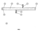
- FIG. 3 is a cross sectional view of a backwash body, according to an embodiment of the invention.
- FIG. 4 is a cross sectional view of a guide and a nozzle, according to an embodiment of the invention.
- FIG. 6 is a cross sectional view of a guide and a nozzle, according to another embodiment of the invention.
- FIG. 7 is a cross sectional view of a guide and a nozzle, according to a further embodiment of the invention.
- FIG. 8 is a flow chart illustrating a method for cleaning a filtering system, according to an embodiment of the invention.
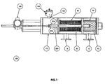
- FIG. 1 is a cross sectional view of filtering system 100, according to an embodiment of the invention.
- the cross section is made along an imaginary longitudinal axis of the filtering system.
- Filtering system 100 can include one or more filters. It usually includes a coarse filter as well as a fine filter. For simplicity of explanation it is assumed that filtering system 100 includes a cylindrical coarse filter 20 and a substantially cylindrical filter 40 that is also refereed to as fine filter 40.
- the coarse filter 20 can be subjected to a backwash operation, but this is not necessarily so.
- backwash operation of fine filter 40 refers to backwash operation of fine filter 40.
- Filtering system 100 includes an elongated tube shaped housing 170 having fluid inlet 10 for a connection with a fluid supply duct (not illustrated), through which the fluid enters a preliminary filtering chamber 90.
- the preliminary filtering chamber 90 is opened to a final filtering chamber 30 through the coarse filter 20 that is adapted to removing rough particles from the fluid.
- the pre-filtered fluid which passes the coarse filter 20 flows through the fine filter 40 to the filtered fluid chamber 30 and to the fluid outlet 160 adapted for a connection with a filtered fluid duct (not illustrated).
- the preliminary filtering chamber 90 and the filtered fluid chamber 30 are two compartments within one tube shaped envelope.
- a backwash body 200 is movably mounted within the filter housing 170.
- the backwash body 200 includes an elongated hollow portion 202 (of FIG. 3 ), and at least one hollow guide, such as guides 210 and 220 (of FIG. 3 ), that extend from the hollow portion 202 towards the fine filter 40.
- the backwash body 200 is in contact with at least one nozzle, such as nozzles 230 and 240 (of FIG. 3 ) that can move, conveniently along guides 210 and 220, towards the inner face of the fine filter 40 during a backwash operation.
- the elongated hollow portion 202 includes one or more outlets, such as outlets 204 and 206 (of FIG. 3 ) that are located within the filtered fluid chamber 30.
- the nozzle 230 further move towards the inner face of fine filter 40 such as to increase the efficiency of the backwash operation.
- the nozzles further perform a radial movement towards the inner face of fine filter 40.
- the backwash operation is usually activated according to a differential pressure sensor gauge that is adapted for identifying a predetermined differential pressure between different portions of the filtering system, indicating that a certain amount of dirt blocks the filter, thus a cleaning operation is required.
- the backwash operation can be initiated, additionally or alternatively, in a periodic manner, in a random manner, in a quasi-random manner, automatically, manually, in response to a request to perform such as backwash operation, and the like.
- the helical movement can be induced by a motor, by hydraulic mechanisms, automatically or manually, and the like.
- FIG. 1 illustrates filtering system 100 that includes an electrical motor 160 that induces the helical movement.
- the driving mechanism translates the rotation of the motor to a helical movement of the backwash body 200.
- the direction (clockwise or counterclockwise) of the rotation of the backwash body is dictated by the rotation direction of the motor 160.
- the motor 160 can be activated in various manners.
- the direction of the rotation can be switched according to the location of the backwash body 200, in response to the number of rotations and/or in response to rotation periods.
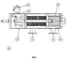
- FIG. 2 is a cross sectional view of filtering system 100', according to an embodiment of the invention.
- Filtering system 100' does not include a motor 160 but includes a backwash body 200 that includes two relatively large hollow guides 250 that are shaped so that the propagation of fluid within the filtered fluid chamber 30 (towards the backwash valve 140) rotates the fins. This rotation is then translated to a helical movement.
- These guides can also be referred to as jets or as an hydraulic motor.
- the nozzles 230 and 240 are hollow such as to allow fluid, dirt and particles to propagate towards the backwash body 200.
- the guides 210 and 220 and accordingly the nozzles 230 and 240 are usually spaced apart from each other. It is further noted that the amount of guides can differ then two. Conveniently, the different guides are positioned such that during the helical movement of the backwash body 200 substantially the entire fine filter 40 is backwashed.
- the suction operation is generated automatically by the pressure-difference between the pressure of the fluid within the filter housing 170 and the pressure of the free atmosphere to which the backwash valve 140 is opened during the backwash operation.
- FIG. 4 is a cross sectional view of guide 210 and nozzle 230, according to an embodiment of the invention.
- Guide 210 has a cylindrical shape.
- FIG. 4 illustrates a guide 210 that includes an upper portion 212 and a lower portion 214.
- the upper portion 212 is thinner than the lower portion 214 such as to define a step 216 that limits the radial movement of nozzle 230 towards the elongated hollow portion 202.
- the nozzle 230 can move along an imaginary radial axis that is substantially perpendicular to the imaginary longitudinal axis of the filtering system 100.
- nozzle 230 moves along guide 210, or at least along upper portion 212, while extending towards the inner part of fine filter 40.
- Nozzles 230 can have a cylindrical shape. It is conveniently shaped such as to define an annular space 218 between a portion 232 of the inner face of nozzle 230 and the outer face of guide 210. Another portion 234 of the inner face of nozzle 230 contacts the outer face of guide 210, thus allowing nozzle 230 to move along guide 210.
- the annular space 218 reduces the friction between nozzle 230 and guide 210. It is noted that other shapes (of the nozzle, guides and space) can be used whilst still being in accordance with other embodiments of the present invention.
- a spring 270 placed on the lower portion 214 of guide 210.
- the spring 270 contacts a inner edge 236 of nozzle 230 and forces the nozzle 230 to move towards the inner face of fine filter 40.
- the lower end 236 of nozzle can include an annular recess or annular step that are shaped such as to contact one end of the spring 270.
- the lower end 236 of nozzle 230 can also include a step of a recess that is shaped according to step 216 of guide 210.
- FIG. 4 illustrates a spring 270 that cause the nozzle 230 to track a pattern defined by the inner face of the fine filter 40, and optionally by dirt that is positioned between the nozzle and the inner face of the fine filter 40.
- the nozzle can be shaped such that the fluid within the filter housing forces the nozzle to substantially contact the inner face of fine filter 40 during the backwash operation.
- the centrifugal force and/or gravity force the nozzle to move towards the inner face of fine filter 40.
- the fluid forces the nozzle to maintain in proximity to the inner face of the fine filter 40 (or near dirt positioned between the nozzle 230 and the inner face of the fine filter 40).
- FIG. 5 is a cross sectional view of a guide 220 and a nozzle 240, according to another embodiment of the invention.
- Nozzle 240 includes an outer edge 242 and an inner edge 244.
- the outer edge 242 faces an inner face of fine filter 40.
- the area of the outer edge 242 is smaller than the area of the inner edge 244.
- an upper portion of nozzle that is defined by the outer edge 242 is thinner that a lower portion of the nozzle as defined by the inner edge 244 of nozzle 240. This can be achieved in various manners such as but not limited by defining an annular recess 246 within outer edge 244.
- outer edge 244 can be shaped in various manners.
- the shape of outer edge 244 may correspond to the shape of fine filter 40. It can be curved, include multiple angled surfaces and the like.
- FIG. 6 is a cross sectional view of a guide 210' and a nozzle 230', according to a further embodiment of the invention.
- Guide 210' includes an annular recess 211' and a ring 213' that is partially located within the annular recess 211'.
- the ring 213' limits the movement of nozzle 230' towards the elongated hollow portion 202.
- Nozzle 230' is shaped such that during the backwash operation the fluid that flows towards the backwash outlet forces it to maintain in proximity to the inner face of the fine filter 40 (or near dirt positioned between the nozzle 230' and the inner face of the fine filter 40).
- the inner face of nozzle 230' is also shaped such as to define two annular spaces between the inner face of nozzle 230' and the outer face of guide 210'.
- FIG. 7 illustrates two possible positions of a nozzle, according to an embodiment of the invention.
- Nozzle 230 can move between two positions - an upper position 280 (closer to the inner face of fine filter 40) and a lower position 290 (closer to the elongated hollow portion 202).
- the guide 210 is illustrated as having a recess 215 for easing the fastening of the guide 210.
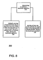
- FIG. 8 is a flow chart illustrating method 300 for cleaning a filtering system, according to an embodiment of the invention.
- Method 300 starts by stage 310 of determining to perform a backwash operation.
- Stage 310 is followed by stages 320 and 330.
- Stage 320 includes helically moving a backwash body that is movably mounted within a filter housing such as to scan an inner face of a substantially cylindrical filter, during the backwash operation.
- Stage 330 includes moving at least one nozzle towards the inner face of the substantially cylindrical filter, during the backwash operation.
- Stages 320 and 330 can be continued until the backwash operation terminates. Conveniently once the backwash operation terminates a filtering process initiates.
- stage 330 includes moving the at least one nozzle until it contacts at least one of the following: (i) an inner face of the substantially cylindrical filter, and (ii) dirt that is positioned between the inner face of the substantially cylindrical filter and the nozzle.
- stage 330 includes moving the at least one nozzle until it loosely contacts an inner face of the substantially cylindrical filter or dirt that is positioned between the inner face of the substantially cylindrical filter and the nozzle.
- stage 330 includes moving the at least one nozzle until it is positioned at a small distance from at least one of the following: (i) an inner face of the substantially cylindrical filter, and (ii) dirt that is positioned between the inner face of the substantially cylindrical filter and the nozzle.
- stage 330 includes moving the at least one nozzle by the fluid within the filter housing.
- stage 330 can include maintaining, by the fluid that flows during the backwash operation, the at least one nozzle in proximity to the inner face of the substantially cylindrical filter.
- the fluid can cause the at least one nozzle to contact (and even loosely contact) the inner face of the substantially cylindrical filter or dirt that is positioned between the inner face of the substantially cylindrical filter and the nozzle.
- stage 330 involves moving the at least one nozzle by a spring.
Abstract
Description
- The present invention relates to methods for cleaning a filtering system and to filtering systems having cleaning capabilities.
- Filtering systems are used in various fields such as but not limited to filtration of fluids, irrigation water, recycling of sewage and industrial waste water, recycling of cooling towers water, filtration and purification of drinking water etc.
- Typical filtering systems include a coarse filter and a fine filter. One inevitable problem of many existing filtering systems is the accumulation of sediments on the filters and especially of the fine filter, blocking it and lowering the flow rate until totally preventing it. Thus, plain filtration systems have to be treated occasionally by cleaning the used blocked filtering element or by replacing it with a clean one, which means interrupting and stopping the filtration process from time to time.
- Self-cleaning filtering systems are known in the art. Self-cleaning filtering systems usually clean a cylindrically shaped fine filter by scanning it by a backwash body. The following patents and patent applications illustrate some prior art self-cleaning filters:
U.S. patent 6283305 of Madea et al. , titled "Filter apparatus with backwashing mechanism";U.S. patent 6419823 of DeLonge et al. titled "Apparatus and method for sanitizing and cleaning a filter system";U.S. patent 4295963 of Drori titled "Backwashable fluid filter"; andU.S. patent 6267879 of Gil. During a backwash operation a pressure difference is introduced between a backwash outlet and the filter that is being cleaned.DE 40 07 893 discloses a movable water screen cleaning device, comprising a telescoping nozzle, arranged to suck clean a curved, but non-cylindrical, water screen. - A typical backwash body includes multiple nozzles that are fixed to the backwash body and are relatively distant from the cylindrically shaped filter, so that (a) dirt (that can include relatively large particles) that is located between the nozzle and the inner part of the filter, (b) filter deformations, or (c) filter inaccuracies will not slow down the movement of the backwash body, or even stop the movement of the backwash body. In addition, this distance also prevents excess friction between the nozzle and the filter.
- This distance reduces the efficiency of the backwash operation.
- There is a need to provide efficient and improved methods for cleaning a filtering system and filtering systems having self-cleaning capabilities.
- According to the present invention a filtering system is provided as set out in claim 1.
- Conveniently, the at least one nozzle is adapted to contact, during the backwash operation, at least one of the following elements: (i) an inner face of the substantially cylindrical filter, or (ii) dirt that is positioned between the inner face of the substantially cylindrical filter and the nozzle.
- According to an embodiment of the invention the at least one nozzle can loosely contact either one of elements (i) or (ii).
- According to an embodiment of the invention the at least one nozzle is adapted to be positioned in proximity to at least one of elements (i) and (ii).
- The nozzle is shaped such that fluid within the filter housing forces the nozzle to move towards the substantially cylindrical filter during the backwash operation.
- Conveniently, an outer edge of the nozzle faces an inner face of the substantially cylindrical filter. The area of the outer edge is smaller than an area of a inner edge of the nozzle.
- Conveniently, the at least one nozzle is shaped such that the fluid within the filter housing forces the nozzle to contact, or loosely contact, during the backwash operation, at least one of elements (i) and (ii).
- According to an embodiment of the invention the backwash body further includes a spring that forces a corresponding nozzle to move towards the substantially cylindrical filter. Conveniently the spring can force the corresponding nozzle to contact, to loosely contact at least one of elements (i) and (ii).
- According to an embodiment of the invention the filtering system includes at least one nozzle-limiting element for limiting a movement of at least one corresponding nozzle.
- According to an embodiment of the invention the backwash body includes at least one hollow guide and at least one nozzle is adapted to move along a corresponding hollow guide.
- According to the invention, a method for cleaning a filtering system is provided as set out in claim 11.
- Conveniently, the method includes moving the at least one nozzle until it contacts or loosely contacts at least one of elements (i) or (ii).
- Conveniently, the method includes moving the at least one nozzle until it is positioned at a small distance from at least one of elements (i) or (ii).
- Conveniently, the method comprises maintaining the at least one nozzle in proximity to at least one of elements (i) and (ii) by the fluid the flows through the filtering system, during the backwash operation.
- Conveniently, the fluid that flows during the backwash operation can cause the at least one nozzle to contact (or maintain in contact with) at least one of elements (i) and (ii). Said contact can be a loose contact.
- Conveniently, the method includes moving the at least one nozzle by at least one corresponding spring.
- The present invention will be understood and appreciated more fully from the following detailed description taken in conjunction with the drawings in which:
-
FIG. 1 is a cross sectional view of a filtering system, according to an embodiment of the invention; -
FIG. 2 is a cross sectional view of a filtering system, according to another embodiment of the invention; -
FIG. 3 is a cross sectional view of a backwash body, according to an embodiment of the invention; -
FIG. 4 is a cross sectional view of a guide and a nozzle, according to an embodiment of the invention; -
FIG. 6 is a cross sectional view of a guide and a nozzle, according to another embodiment of the invention; -
FIG. 7 is a cross sectional view of a guide and a nozzle, according to a further embodiment of the invention; and -
FIG. 8 is a flow chart illustrating a method for cleaning a filtering system, according to an embodiment of the invention. -
FIG. 1 is a cross sectional view offiltering system 100, according to an embodiment of the invention. The cross section is made along an imaginary longitudinal axis of the filtering system. -
Filtering system 100 can include one or more filters. It usually includes a coarse filter as well as a fine filter. For simplicity of explanation it is assumed thatfiltering system 100 includes a cylindricalcoarse filter 20 and a substantiallycylindrical filter 40 that is also refereed to asfine filter 40. - It is noted that the
coarse filter 20 can be subjected to a backwash operation, but this is not necessarily so. For convenience of explanation the following description refers to backwash operation offine filter 40. -
Filtering system 100 includes an elongated tube shapedhousing 170 having fluid inlet 10 for a connection with a fluid supply duct (not illustrated), through which the fluid enters apreliminary filtering chamber 90. Thepreliminary filtering chamber 90 is opened to afinal filtering chamber 30 through thecoarse filter 20 that is adapted to removing rough particles from the fluid. - The pre-filtered fluid which passes the
coarse filter 20 flows through thefine filter 40 to the filteredfluid chamber 30 and to thefluid outlet 160 adapted for a connection with a filtered fluid duct (not illustrated). Conveniently, thepreliminary filtering chamber 90 and the filteredfluid chamber 30 are two compartments within one tube shaped envelope. - A
backwash body 200 is movably mounted within thefilter housing 170. Thebackwash body 200 includes an elongated hollow portion 202 (ofFIG. 3 ), and at least one hollow guide, such asguides 210 and 220 (ofFIG. 3 ), that extend from thehollow portion 202 towards thefine filter 40. Thebackwash body 200 is in contact with at least one nozzle, such asnozzles 230 and 240 (ofFIG. 3 ) that can move, conveniently alongguides fine filter 40 during a backwash operation. The elongatedhollow portion 202 includes one or more outlets, such asoutlets 204 and 206 (ofFIG. 3 ) that are located within the filteredfluid chamber 30. - While the
backwash body 200 and especially the elongatedhollow portion 202 performs a helical movement within thefilter housing 170, thenozzle 230 further move towards the inner face offine filter 40 such as to increase the efficiency of the backwash operation. - Thus, while the
backwash body 200 moves along an imaginary longitudinal axis of thefiltering system 100 and also rotates (performs a tangential movement) about that imaginary longitudinal axis, the nozzles further perform a radial movement towards the inner face offine filter 40. - The backwash operation is usually activated according to a differential pressure sensor gauge that is adapted for identifying a predetermined differential pressure between different portions of the filtering system, indicating that a certain amount of dirt blocks the filter, thus a cleaning operation is required. The backwash operation can be initiated, additionally or alternatively, in a periodic manner, in a random manner, in a quasi-random manner, automatically, manually, in response to a request to perform such as backwash operation, and the like.
- The helical movement can be induced by a motor, by hydraulic mechanisms, automatically or manually, and the like.
-
FIG. 1 illustratesfiltering system 100 that includes anelectrical motor 160 that induces the helical movement. Such motors as well as driving mechanisms are known in the art and some are illustrated by the patents that were mentioned above. In general, the driving mechanism translates the rotation of the motor to a helical movement of thebackwash body 200. The direction (clockwise or counterclockwise) of the rotation of the backwash body is dictated by the rotation direction of themotor 160. Themotor 160 can be activated in various manners. The direction of the rotation can be switched according to the location of thebackwash body 200, in response to the number of rotations and/or in response to rotation periods. -
FIG. 2 is a cross sectional view of filtering system 100', according to an embodiment of the invention. - Filtering system 100' does not include a
motor 160 but includes abackwash body 200 that includes two relatively largehollow guides 250 that are shaped so that the propagation of fluid within the filtered fluid chamber 30 (towards the backwash valve 140) rotates the fins. This rotation is then translated to a helical movement. These guides can also be referred to as jets or as an hydraulic motor. - The
nozzles backwash body 200. - The
guides nozzles backwash body 200 substantially the entirefine filter 40 is backwashed. - During the backwash operation fluid, dirt and particles are sucked into the
nozzles backwash body 200, the filteredfluid chamber 30, thebackwash outlet 165 and the openedbackwash valve 140. - Conveniently, the suction operation is generated automatically by the pressure-difference between the pressure of the fluid within the
filter housing 170 and the pressure of the free atmosphere to which thebackwash valve 140 is opened during the backwash operation. -
FIG. 4 is a cross sectional view ofguide 210 andnozzle 230, according to an embodiment of the invention. -
Guide 210 has a cylindrical shape.FIG. 4 illustrates aguide 210 that includes anupper portion 212 and alower portion 214. Theupper portion 212 is thinner than thelower portion 214 such as to define astep 216 that limits the radial movement ofnozzle 230 towards the elongatedhollow portion 202. - The
nozzle 230 can move along an imaginary radial axis that is substantially perpendicular to the imaginary longitudinal axis of thefiltering system 100. - Conveniently,
nozzle 230 moves alongguide 210, or at least alongupper portion 212, while extending towards the inner part offine filter 40. -
Nozzles 230 can have a cylindrical shape. It is conveniently shaped such as to define anannular space 218 between aportion 232 of the inner face ofnozzle 230 and the outer face ofguide 210. Anotherportion 234 of the inner face ofnozzle 230 contacts the outer face ofguide 210, thus allowingnozzle 230 to move alongguide 210. Theannular space 218 reduces the friction betweennozzle 230 and guide 210. It is noted that other shapes (of the nozzle, guides and space) can be used whilst still being in accordance with other embodiments of the present invention. - A
spring 270 placed on thelower portion 214 ofguide 210. Thespring 270 contacts ainner edge 236 ofnozzle 230 and forces thenozzle 230 to move towards the inner face offine filter 40. Thelower end 236 of nozzle can include an annular recess or annular step that are shaped such as to contact one end of thespring 270. Thelower end 236 ofnozzle 230 can also include a step of a recess that is shaped according to step 216 ofguide 210. - If
fine filter 40 was totally clean and was ideally cylindrical then the distance between the fine filter and the elongatedhollow portion 202 is maintained fixed. In reality the distance can change due to filter deformations, filter manufacturing inaccuracies, and filter (or backwash body) misalignment. In addition, dirt can be stuck between the nozzle and thefine filter 40. In over to provide efficient cleaning in these conditions the distance between the nozzle end and an imaginary longitudinal axis of the filtering system can be adjusted in various manners.FIG. 4 illustrates aspring 270 that cause thenozzle 230 to track a pattern defined by the inner face of thefine filter 40, and optionally by dirt that is positioned between the nozzle and the inner face of thefine filter 40. - According to an embodiment of the invention the nozzle can be shaped such that the fluid within the filter housing forces the nozzle to substantially contact the inner face of
fine filter 40 during the backwash operation. - Conveniently, the centrifugal force and/or gravity (when the nozzle is below hollow elongated portion 202) force the nozzle to move towards the inner face of
fine filter 40. Once the nozzle is proximate to the inner face of thefine filter 40 the fluid forces the nozzle to maintain in proximity to the inner face of the fine filter 40 (or near dirt positioned between thenozzle 230 and the inner face of the fine filter 40). -
FIG. 5 is a cross sectional view of aguide 220 and anozzle 240, according to another embodiment of the invention. -
Nozzle 240 includes anouter edge 242 and aninner edge 244. Theouter edge 242 faces an inner face offine filter 40. The area of theouter edge 242 is smaller than the area of theinner edge 244. - During the backwash operation fluid flows through the
final filtering chamber 30 toward the space defined withinnozzle 240. Due to this flow theouter edge 242 ofnozzle 240 is pushed away from thefine filter 40 while the inner edge is pushed towards the fine filter. Because the area of theinner edge 244 is larger than the area of theouter edge 242 ofnozzle 240 the overall effect of the fluid flow is to pushnozzle 240 towards the inner face offine filter 40. - Conveniently, an upper portion of nozzle that is defined by the
outer edge 242 is thinner that a lower portion of the nozzle as defined by theinner edge 244 ofnozzle 240. This can be achieved in various manners such as but not limited by defining an annular recess 246 withinouter edge 244. - It is noted that the
outer edge 244 can be shaped in various manners. The shape ofouter edge 244 may correspond to the shape offine filter 40. It can be curved, include multiple angled surfaces and the like. -
FIG. 6 is a cross sectional view of a guide 210' and a nozzle 230', according to a further embodiment of the invention. - Guide 210' includes an annular recess 211' and a ring 213' that is partially located within the annular recess 211'. The ring 213' limits the movement of nozzle 230' towards the elongated
hollow portion 202. - Nozzle 230' is shaped such that during the backwash operation the fluid that flows towards the backwash outlet forces it to maintain in proximity to the inner face of the fine filter 40 (or near dirt positioned between the nozzle 230' and the inner face of the fine filter 40).
- The inner face of nozzle 230' is also shaped such as to define two annular spaces between the inner face of nozzle 230' and the outer face of guide 210'.
-
FIG. 7 illustrates two possible positions of a nozzle, according to an embodiment of the invention. -
Nozzle 230 can move between two positions - an upper position 280 (closer to the inner face of fine filter 40) and a lower position 290 (closer to the elongated hollow portion 202). The dashed curves illustrated theupper position 280. - The
guide 210 is illustrated as having arecess 215 for easing the fastening of theguide 210. -
FIG. 8 is a flowchart illustrating method 300 for cleaning a filtering system, according to an embodiment of the invention. -
Method 300 starts bystage 310 of determining to perform a backwash operation. -
Stage 310 is followed bystages 320 and 330. Stage 320 includes helically moving a backwash body that is movably mounted within a filter housing such as to scan an inner face of a substantially cylindrical filter, during the backwash operation. -
Stage 330 includes moving at least one nozzle towards the inner face of the substantially cylindrical filter, during the backwash operation. -
Stages 320 and 330 can be continued until the backwash operation terminates. Conveniently once the backwash operation terminates a filtering process initiates. - Conveniently,
stage 330 includes moving the at least one nozzle until it contacts at least one of the following: (i) an inner face of the substantially cylindrical filter, and (ii) dirt that is positioned between the inner face of the substantially cylindrical filter and the nozzle. - Conveniently,
stage 330 includes moving the at least one nozzle until it loosely contacts an inner face of the substantially cylindrical filter or dirt that is positioned between the inner face of the substantially cylindrical filter and the nozzle. - Conveniently,
stage 330 includes moving the at least one nozzle until it is positioned at a small distance from at least one of the following: (i) an inner face of the substantially cylindrical filter, and (ii) dirt that is positioned between the inner face of the substantially cylindrical filter and the nozzle. - Conveniently,
stage 330 includes moving the at least one nozzle by the fluid within the filter housing. - According to an embodiment of the
invention stage 330 can include maintaining, by the fluid that flows during the backwash operation, the at least one nozzle in proximity to the inner face of the substantially cylindrical filter. - Conveniently the fluid can cause the at least one nozzle to contact (and even loosely contact) the inner face of the substantially cylindrical filter or dirt that is positioned between the inner face of the substantially cylindrical filter and the nozzle.
- Conveniently,
stage 330 involves moving the at least one nozzle by a spring.
Claims (20)
- A filtering system (100) comprising:a filter housing (170) comprising a fluid inlet (10) and a fluid outlet (16);a filter located within the filter housing;a backwash body (200) movably mounted within the filter housing (170) for performing a helical movement while backwashing the filter(40); andat least one nozzle (230, 230', 240) in connection with the backwash body,characterised in thatthe filter is a substantially cylindrical filter (40);the at least one nozzle is adapted to move towards the substantially cylindrical filter so that during a backwash operation, when the nozzle performs a helical movement, and is proximate to, the inner surface of the cylindrical filter (40), the nozzle is maintained in proximity to an inner face of the substantially cylindrical filter, or in proximity to dirt positioned between the nozzle and an inner face of the substantially cylindrical filter;wherein the at least one nozzle moves between two positions - an upper position that is closer to the inner face of the cylindrical filter and a lower position that is closer to an elongated hollow portion of the backwash body;wherein the at least one nozzle is shaped such that fluid within the filter housing (170) forces the at least one nozzle to move towards the substantially cylindrical filter (40) during the backwash operation; andwherein the system comprises a differential pressure sensor gauge that activates the backwash operation.
- The filtering system (100) according to claim 1 wherein the at least one nozzle (230, 230', 240) is adapted to contact, during the backwash operation, at least one of the following:(i) an inner face of the substantially cylindrical filter (40), and(ii) dirt that is positioned between the inner face of the substantially cylindrical filter (40) and the nozzle (230, 230', 240).
- The filtering system (100) according to claim 1 wherein the at least one nozzle (230, 230', 240) is adapted to loosely contact, during the backwash operation, at least one of the following:(i) an inner face of the substantially cylindrical filter(40), and(ii) dirt that is positioned between the inner face of the substantially cylindrical filter (40) and the nozzle (230, 230', 240).
- The filtering system (100) according to claim 1 wherein the at least one nozzle (230, 230', 240) is adapted to be positioned in proximity to at least one of the following:(i) an inner face of the substantially cylindrical filter(40), and(ii) dirt that is positioned between the inner face of the substantially cylindrical filter (40) and the nozzle(230, 230', 240).
- The filtering system (100) according to any preceding claim wherein an outer edge (242) of the nozzle (230, 230', 240) faces an inner face of the substantially cylindrical filter (40) and wherein an area of the outer edge (242) is smaller than an area of a inner edge (244) of the nozzle (230, 230', 240).
- The filtering system (100) according to any preceding claim wherein the at least one nozzle (230, 230', 240) is shaped such that the fluid within the filter housing (170) forces the nozzle (230, 230', 240) to contact, during the backwash operation, at least one of the following:(i) an inner face of the substantially cylindrical filter(40), and(ii) dirt that is positioned between the inner face of the substantially cylindrical filter (40) and the nozzle (230, 230', 240).
- The filtering system (100) according to any preceding claim wherein the backwash body (200) further comprises a spring (270) that forces a corresponding nozzle (230, 230', 240) to move towards the substantially cylindrical filter (40).
- The filtering system (100) according to any preceding claim wherein a backwash body (200) further comprises a spring (270) that forces a corresponding nozzle (230, 230', 240) to contact, during the backwash operation, at least one of the following:(i) an inner face of the substantially cylindrical filter(40), and(ii) dirt that is positioned between the inner face of the substantially cylindrical filter (40) and the nozzle(230, 230', 240).
- The filtering system (100) according to any preceding claim further comprising at least one nozzle limiting element for limiting a movement of at least one corresponding nozzle (230, 230', 240).
- The filtering system (100) according to any preceding claim wherein the backwash body (200) comprises at least one hollow guide and wherein at least one nozzle (230, 230', 240) is adapted to move along a corresponding hollow guide.
- A method (300) for cleaning a filtering system (100), the method comprising:determining (310) to perform a backwash operation;characterised in that the method further comprises:helically moving (320) a backwash body (200) that is movably mounted within a filter housing (170) such as to scan an inner face of a substantially cylindrical filter (40), during the backwash operation; andmoving (330), by force of fluid within the filter housing (170), at least one nozzle (230, 230', 240) towards the inner face of the substantially cylindrical filter (40), during the backwash operation;wherein the at least one nozzle moves between two positions - an upper position that is closer to the inner face of the cylindrical filter and a lower position that is closer to an elongated hollow portion of the backwash body.
- The method according to claim 11 wherein the moving comprises moving the at least one nozzle(230, 230', 240) until it contacts at least one of the following:(i) an inner face of the substantially cylindrical filter(40), and(ii) dirt that is positioned between the inner face of the substantially cylindrical filter (40) and the nozzle (230, 230', 240).
- The method according to claim 11 wherein the moving comprises moving the at least one radial backwash element until it loosely contacts at least one of the following:(i) an inner face of the substantially cylindrical filter(40), and(ii) dirt that is positioned between the inner face of the substantially cylindrical filter (40) and the nozzle (230, 230', 240).
- The method according to claim 11 wherein the moving comprises moving the at least one nozzle (230, 230', 240) until it is positioned at a small distance from at least one of the following:(i) an inner face of the substantially cylindrical filter(40), and(ii) dirt that is positioned between the inner face of the substantially cylindrical filter (40) and the nozzle (230, 230', 240).
- The method according to claim 11 wherein the moving comprises moving the at least one nozzle (230, 230', 240) until it contacts at least one of the following:(i) an inner face of the substantially cylindrical filter (40), and(ii) dirt that is positioned between the inner face of the substantially cylindrical filter (40) and the nozzle (230, 230', 240).
- The method according to any one of claims 11 to 15 wherein the moving comprising moving the at least one nozzle (230, 230', 240) by at least one corresponding spring.
- The method according to claim 16 wherein the moving comprises moving the at least one nozzle (230, 230', 240) until it contacts at least one of the following:(i) an inner face of the substantially cylindrical filter (40), and(ii) dirt that is positioned between the inner face of the substantially cylindrical filter (40) and the nozzle (230, 230', 240).
- The method according to any one of claims 11 to 17 comprising maintaining, during the backwash operation, the at least one nozzle (230, 230', 240) in proximity to at least one of the following:(i) an inner face of the substantially cylindrical filter (40), and(ii) dirt that is positioned between the inner face of the substantially cylindrical filter (40) and the nozzle (230, 230', 240).
- The method according to any one of claims 11 to 18 comprising maintaining, by fluid that flows during the backwash operation, the at least one nozzle (230, 230', 240) in proximity to at least one of the following:(i) an inner face of the substantially cylindrical filter (40), and(ii) dirt that is positioned between the inner face of the substantially cylindrical filter (40) and the nozzle (230, 230', 240).
- The method according to any one of claims 11 to 18 comprising maintaining, by fluid that flows during the backwash operation, the at least one nozzle (230, 230', 240) in contact with at least one of the following:(i) an inner face of the substantially cylindrical filter (40), and(ii) dirt that is positioned between the inner face of the substantially cylindrical filter (40) and the nozzle(230, 230', 240).
Priority Applications (4)
| Application Number | Priority Date | Filing Date | Title |
|---|---|---|---|
| ES05257010T ES2371347T3 (en) | 2005-11-14 | 2005-11-14 | CLEANING PROCEDURE OF A FILTER SYSTEM AND A FILTER SYSTEM THAT HAS CLEANING CAPABILITIES. |
| AT05257010T ATE515303T1 (en) | 2005-11-14 | 2005-11-14 | FILTER CLEANING METHOD AND FILTRATION SYSTEM WITH CLEANING DEVICES |
| EP05257010A EP1785178B1 (en) | 2005-11-14 | 2005-11-14 | Method for cleaning a filtering system and a filtering system having cleaning capabilities. |
| US11/273,669 US20070199885A1 (en) | 2005-11-14 | 2005-11-14 | Method for cleaning a filtering system and a filtering system having cleaning capabilities |
Applications Claiming Priority (2)
| Application Number | Priority Date | Filing Date | Title |
|---|---|---|---|
| EP05257010A EP1785178B1 (en) | 2005-11-14 | 2005-11-14 | Method for cleaning a filtering system and a filtering system having cleaning capabilities. |
| US11/273,669 US20070199885A1 (en) | 2005-11-14 | 2005-11-14 | Method for cleaning a filtering system and a filtering system having cleaning capabilities |
Publications (2)
| Publication Number | Publication Date |
|---|---|
| EP1785178A1 EP1785178A1 (en) | 2007-05-16 |
| EP1785178B1 true EP1785178B1 (en) | 2011-07-06 |
Family
ID=42734824
Family Applications (1)
| Application Number | Title | Priority Date | Filing Date |
|---|---|---|---|
| EP05257010A Not-in-force EP1785178B1 (en) | 2005-11-14 | 2005-11-14 | Method for cleaning a filtering system and a filtering system having cleaning capabilities. |
Country Status (3)
| Country | Link |
|---|---|
| US (1) | US20070199885A1 (en) |
| EP (1) | EP1785178B1 (en) |
| AT (1) | ATE515303T1 (en) |
Cited By (1)
| Publication number | Priority date | Publication date | Assignee | Title |
|---|---|---|---|---|
| RU189133U1 (en) * | 2018-10-05 | 2019-05-13 | Амиад Вотер Системс Лтд. | UNIVERSALLY CONNECTED FILTER SYSTEM |
Families Citing this family (16)
| Publication number | Priority date | Publication date | Assignee | Title |
|---|---|---|---|---|
| ES2424440T3 (en) * | 2007-05-30 | 2013-10-02 | Dominion Engineering, Inc. | Apparatus and procedure for increasing filter capacity using ultrasonic regeneration |
| US20090050582A1 (en) | 2007-08-23 | 2009-02-26 | Shmuel Gil | Self-Cleaning System For Filter |
| WO2011058556A2 (en) | 2009-11-12 | 2011-05-19 | The Ballast Safe Filtration Company Ltd. | Filter proximity nozzle |
| CA2808323A1 (en) | 2010-08-20 | 2012-02-23 | Trojan Technologies | Fluid filter device |
| US8647516B2 (en) * | 2010-09-03 | 2014-02-11 | Johnny Leon LOVE | Filtration method with self-cleaning filter assembly |
| GB2487404A (en) | 2011-01-20 | 2012-07-25 | Sea Lix As | Rotor for extracting energy from bidirectional fluid flows |
| US20130026111A1 (en) * | 2011-05-23 | 2013-01-31 | Odis Irrigation Equipment Ltd. | Filtering system with backwash capabilities |
| GB2500900B (en) * | 2012-04-04 | 2019-10-16 | Sea Lix As | Filter Cleaning |
| US9561454B2 (en) * | 2012-10-09 | 2017-02-07 | Ovivo Inc. | Debris filter with splitter bar |
| US10646801B2 (en) * | 2013-09-12 | 2020-05-12 | Antel Aritma Tesisleri Insaat Sanayi Ve Ticaret Anonim Sirketi | Nozzle-brush automatic cleaning filter with motor reducer |
| US9314718B2 (en) * | 2013-11-10 | 2016-04-19 | Yamit Filtration & Water Treatment Ltd | Backwash arrangement for cleaning a cylindrical filter screen |
| WO2015130253A1 (en) * | 2014-02-28 | 2015-09-03 | Antel Aritma Tesisleri Insaat Sanayi Ve Ticaret A.S. | Filtration assembly for gradually screening of fine and coarse particles in a single operational unit |
| US10183243B2 (en) * | 2015-07-08 | 2019-01-22 | Filter Safe Ltd | Micronic automatic filter |
| DE102017002646A1 (en) | 2017-03-18 | 2018-09-20 | Hydac Process Technology Gmbh | filter means |
| NO345889B1 (en) * | 2020-02-19 | 2021-09-27 | Tenko As | Filter systems and methods |
| CN111794355B (en) * | 2020-07-04 | 2021-06-22 | 深圳市润博建设有限公司 | Municipal administration pipeline simply cuts dirty device |
Family Cites Families (11)
| Publication number | Priority date | Publication date | Assignee | Title |
|---|---|---|---|---|
| AU5250379A (en) | 1978-11-17 | 1980-05-22 | Mordeki Drori | Backwashable filter |
| DE4007893A1 (en) * | 1990-01-06 | 1991-07-11 | Brieden Filtration Gmbh Und Co | Device for cleaning process water, esp. cooling water, using screen - comprises fixed inlet screen kept clean by suction head which traverses its upstream surface under effect of linear or rotational drives |
| GB2265840B (en) * | 1992-04-06 | 1995-05-10 | Locker Wire Weavers Limited | Clarifier and method for cleaning same |
| DE4339268C2 (en) * | 1993-11-18 | 1996-01-25 | Huber Hans Gmbh Maschinen Und | Method and device for filtering and backwashing solid particles from liquids |
| FR2743505B1 (en) * | 1996-01-15 | 1998-02-13 | Cellier Groupe Sa | SELF-CLEANING FILTRATION DEVICE |
| US6337013B1 (en) * | 1997-12-23 | 2002-01-08 | Ontario Power Generation, Inc. | Removable filter with jack sealing device and vacuum cleaning heads |
| JP3462432B2 (en) | 1999-07-30 | 2003-11-05 | Smc株式会社 | Filter device with backwash mechanism |
| US6267879B1 (en) | 1999-08-11 | 2001-07-31 | Odis Irrigation Equipment Ltd. | Continuous liquid filtering apparatus with multi-layer sintered filtering element |
| US6342163B1 (en) | 1999-11-12 | 2002-01-29 | United States Filter Corporation | Apparatus and method for sanitizing and cleaning a filter system |
| CN101014397A (en) * | 2004-07-21 | 2007-08-08 | 阿米阿得过滤系统(1997)有限公司 | Filter cleaning head |
| US7055699B2 (en) * | 2004-09-01 | 2006-06-06 | Amiad Japan Inc. | Self-cleaning mechanical filter |
-
2005
- 2005-11-14 US US11/273,669 patent/US20070199885A1/en not_active Abandoned
- 2005-11-14 EP EP05257010A patent/EP1785178B1/en not_active Not-in-force
- 2005-11-14 AT AT05257010T patent/ATE515303T1/en not_active IP Right Cessation
Cited By (1)
| Publication number | Priority date | Publication date | Assignee | Title |
|---|---|---|---|---|
| RU189133U1 (en) * | 2018-10-05 | 2019-05-13 | Амиад Вотер Системс Лтд. | UNIVERSALLY CONNECTED FILTER SYSTEM |
Also Published As
| Publication number | Publication date |
|---|---|
| EP1785178A1 (en) | 2007-05-16 |
| US20070199885A1 (en) | 2007-08-30 |
| ATE515303T1 (en) | 2011-07-15 |
Similar Documents
| Publication | Publication Date | Title |
|---|---|---|
| EP1785178B1 (en) | Method for cleaning a filtering system and a filtering system having cleaning capabilities. | |
| US6267879B1 (en) | Continuous liquid filtering apparatus with multi-layer sintered filtering element | |
| KR101714726B1 (en) | Filter proximity nozzle | |
| EP2027905A2 (en) | Self-cleaning system for filter | |
| KR100538306B1 (en) | Self-cleaning filtering system | |
| JP2009517204A (en) | Cleaning device | |
| CN1068237C (en) | Liquid filtering apparatus | |
| US6543624B1 (en) | Back-washable filter for liquids | |
| CN1110930A (en) | Revers washable filter, especially used for fluid | |
| CN100560177C (en) | A kind of automatic cleaning well strainer | |
| CN201244396Y (en) | Automatic cleaning screen filter | |
| KR20010000766A (en) | Cyclone system analong filter auto backwash unit | |
| KR101203634B1 (en) | Filtering device of scale with variable mesh | |
| CN207680154U (en) | A kind of sewage-treatment plant | |
| US7396460B2 (en) | Filter element | |
| RU2681193C1 (en) | Filtration system for purification of liquid and gaseous media from mechanical impurities with automatic high pressure regeneration | |
| EP2017231A1 (en) | Method and system for backwashing a filter | |
| KR19990014551A (en) | Auto filtration device | |
| CN215232493U (en) | Automatic back flush filter | |
| KR101745340B1 (en) | Filtering apparatus of fluid | |
| ES2371347T3 (en) | CLEANING PROCEDURE OF A FILTER SYSTEM AND A FILTER SYSTEM THAT HAS CLEANING CAPABILITIES. | |
| KR0175219B1 (en) | Filter backwash device using reversible screw | |
| EP4234063A1 (en) | A filter arrangement, a fluid handling system and a method | |
| KR20240002587A (en) | Acid filtration device for septic tank and septic tank equipped with the filtration device | |
| UA11806U (en) | Self-cleaning hydrodynamic filter |
Legal Events
| Date | Code | Title | Description |
|---|---|---|---|
| PUAI | Public reference made under article 153(3) epc to a published international application that has entered the european phase |
Free format text: ORIGINAL CODE: 0009012 |
|
| AK | Designated contracting states |
Kind code of ref document: A1 Designated state(s): AT BE BG CH CY CZ DE DK EE ES FI FR GB GR HU IE IS IT LI LT LU LV MC NL PL PT RO SE SI SK TR |
|
| AX | Request for extension of the european patent |
Extension state: AL BA HR MK YU |
|
| 17P | Request for examination filed |
Effective date: 20071116 |
|
| 17Q | First examination report despatched |
Effective date: 20071228 |
|
| AKX | Designation fees paid |
Designated state(s): AT BE BG CH CY CZ DE DK EE ES FI FR GB GR HU IE IS IT LI LT LU LV MC NL PL PT RO SE SI SK TR |
|
| GRAP | Despatch of communication of intention to grant a patent |
Free format text: ORIGINAL CODE: EPIDOSNIGR1 |
|
| GRAJ | Information related to disapproval of communication of intention to grant by the applicant or resumption of examination proceedings by the epo deleted |
Free format text: ORIGINAL CODE: EPIDOSDIGR1 |
|
| GRAP | Despatch of communication of intention to grant a patent |
Free format text: ORIGINAL CODE: EPIDOSNIGR1 |
|
| GRAS | Grant fee paid |
Free format text: ORIGINAL CODE: EPIDOSNIGR3 |
|
| GRAA | (expected) grant |
Free format text: ORIGINAL CODE: 0009210 |
|
| AK | Designated contracting states |
Kind code of ref document: B1 Designated state(s): AT BE BG CH CY CZ DE DK EE ES FI FR GB GR HU IE IS IT LI LT LU LV MC NL PL PT RO SE SI SK TR |
|
| REG | Reference to a national code |
Ref country code: GB Ref legal event code: FG4D |
|
| REG | Reference to a national code |
Ref country code: CH Ref legal event code: EP |
|
| REG | Reference to a national code |
Ref country code: IE Ref legal event code: FG4D |
|
| REG | Reference to a national code |
Ref country code: DE Ref legal event code: R096 Ref document number: 602005028839 Country of ref document: DE Effective date: 20110825 |
|
| REG | Reference to a national code |
Ref country code: NL Ref legal event code: T3 |
|
| PG25 | Lapsed in a contracting state [announced via postgrant information from national office to epo] |
Ref country code: SI Free format text: LAPSE BECAUSE OF FAILURE TO SUBMIT A TRANSLATION OF THE DESCRIPTION OR TO PAY THE FEE WITHIN THE PRESCRIBED TIME-LIMIT Effective date: 20110706 |
|
| REG | Reference to a national code |
Ref country code: ES Ref legal event code: FG2A Ref document number: 2371347 Country of ref document: ES Kind code of ref document: T3 Effective date: 20111230 |
|
| REG | Reference to a national code |
Ref country code: AT Ref legal event code: MK05 Ref document number: 515303 Country of ref document: AT Kind code of ref document: T Effective date: 20110706 |
|
| REG | Reference to a national code |
Ref country code: GR Ref legal event code: EP Ref document number: 20110402339 Country of ref document: GR Effective date: 20111117 |
|
| PG25 | Lapsed in a contracting state [announced via postgrant information from national office to epo] |
Ref country code: FI Free format text: LAPSE BECAUSE OF FAILURE TO SUBMIT A TRANSLATION OF THE DESCRIPTION OR TO PAY THE FEE WITHIN THE PRESCRIBED TIME-LIMIT Effective date: 20110706 Ref country code: PT Free format text: LAPSE BECAUSE OF FAILURE TO SUBMIT A TRANSLATION OF THE DESCRIPTION OR TO PAY THE FEE WITHIN THE PRESCRIBED TIME-LIMIT Effective date: 20111107 Ref country code: IS Free format text: LAPSE BECAUSE OF FAILURE TO SUBMIT A TRANSLATION OF THE DESCRIPTION OR TO PAY THE FEE WITHIN THE PRESCRIBED TIME-LIMIT Effective date: 20111106 Ref country code: LT Free format text: LAPSE BECAUSE OF FAILURE TO SUBMIT A TRANSLATION OF THE DESCRIPTION OR TO PAY THE FEE WITHIN THE PRESCRIBED TIME-LIMIT Effective date: 20110706 Ref country code: BE Free format text: LAPSE BECAUSE OF FAILURE TO SUBMIT A TRANSLATION OF THE DESCRIPTION OR TO PAY THE FEE WITHIN THE PRESCRIBED TIME-LIMIT Effective date: 20110706 Ref country code: SE Free format text: LAPSE BECAUSE OF FAILURE TO SUBMIT A TRANSLATION OF THE DESCRIPTION OR TO PAY THE FEE WITHIN THE PRESCRIBED TIME-LIMIT Effective date: 20110706 |
|
| PG25 | Lapsed in a contracting state [announced via postgrant information from national office to epo] |
Ref country code: PL Free format text: LAPSE BECAUSE OF FAILURE TO SUBMIT A TRANSLATION OF THE DESCRIPTION OR TO PAY THE FEE WITHIN THE PRESCRIBED TIME-LIMIT Effective date: 20110706 Ref country code: LV Free format text: LAPSE BECAUSE OF FAILURE TO SUBMIT A TRANSLATION OF THE DESCRIPTION OR TO PAY THE FEE WITHIN THE PRESCRIBED TIME-LIMIT Effective date: 20110706 Ref country code: CY Free format text: LAPSE BECAUSE OF FAILURE TO SUBMIT A TRANSLATION OF THE DESCRIPTION OR TO PAY THE FEE WITHIN THE PRESCRIBED TIME-LIMIT Effective date: 20110706 Ref country code: AT Free format text: LAPSE BECAUSE OF FAILURE TO SUBMIT A TRANSLATION OF THE DESCRIPTION OR TO PAY THE FEE WITHIN THE PRESCRIBED TIME-LIMIT Effective date: 20110706 |
|
| PG25 | Lapsed in a contracting state [announced via postgrant information from national office to epo] |
Ref country code: CZ Free format text: LAPSE BECAUSE OF FAILURE TO SUBMIT A TRANSLATION OF THE DESCRIPTION OR TO PAY THE FEE WITHIN THE PRESCRIBED TIME-LIMIT Effective date: 20110706 Ref country code: SK Free format text: LAPSE BECAUSE OF FAILURE TO SUBMIT A TRANSLATION OF THE DESCRIPTION OR TO PAY THE FEE WITHIN THE PRESCRIBED TIME-LIMIT Effective date: 20110706 |
|
| PLBE | No opposition filed within time limit |
Free format text: ORIGINAL CODE: 0009261 |
|
| STAA | Information on the status of an ep patent application or granted ep patent |
Free format text: STATUS: NO OPPOSITION FILED WITHIN TIME LIMIT |
|
| PG25 | Lapsed in a contracting state [announced via postgrant information from national office to epo] |
Ref country code: EE Free format text: LAPSE BECAUSE OF FAILURE TO SUBMIT A TRANSLATION OF THE DESCRIPTION OR TO PAY THE FEE WITHIN THE PRESCRIBED TIME-LIMIT Effective date: 20110706 Ref country code: RO Free format text: LAPSE BECAUSE OF FAILURE TO SUBMIT A TRANSLATION OF THE DESCRIPTION OR TO PAY THE FEE WITHIN THE PRESCRIBED TIME-LIMIT Effective date: 20110706 |
|
| 26N | No opposition filed |
Effective date: 20120411 |
|
| PG25 | Lapsed in a contracting state [announced via postgrant information from national office to epo] |
Ref country code: DK Free format text: LAPSE BECAUSE OF FAILURE TO SUBMIT A TRANSLATION OF THE DESCRIPTION OR TO PAY THE FEE WITHIN THE PRESCRIBED TIME-LIMIT Effective date: 20110706 Ref country code: MC Free format text: LAPSE BECAUSE OF NON-PAYMENT OF DUE FEES Effective date: 20111130 |
|
| REG | Reference to a national code |
Ref country code: CH Ref legal event code: PL |
|
| PG25 | Lapsed in a contracting state [announced via postgrant information from national office to epo] |
Ref country code: CH Free format text: LAPSE BECAUSE OF NON-PAYMENT OF DUE FEES Effective date: 20111130 Ref country code: LI Free format text: LAPSE BECAUSE OF NON-PAYMENT OF DUE FEES Effective date: 20111130 |
|
| REG | Reference to a national code |
Ref country code: DE Ref legal event code: R097 Ref document number: 602005028839 Country of ref document: DE Effective date: 20120411 |
|
| REG | Reference to a national code |
Ref country code: IE Ref legal event code: MM4A |
|
| REG | Reference to a national code |
Ref country code: DE Ref legal event code: R119 Ref document number: 602005028839 Country of ref document: DE Effective date: 20120601 |
|
| PG25 | Lapsed in a contracting state [announced via postgrant information from national office to epo] |
Ref country code: IE Free format text: LAPSE BECAUSE OF NON-PAYMENT OF DUE FEES Effective date: 20111114 |
|
| PGFP | Annual fee paid to national office [announced via postgrant information from national office to epo] |
Ref country code: FR Payment date: 20121130 Year of fee payment: 8 |
|
| PGFP | Annual fee paid to national office [announced via postgrant information from national office to epo] |
Ref country code: ES Payment date: 20121127 Year of fee payment: 8 Ref country code: GR Payment date: 20121128 Year of fee payment: 8 Ref country code: GB Payment date: 20121120 Year of fee payment: 8 Ref country code: IT Payment date: 20121122 Year of fee payment: 8 |
|
| PGFP | Annual fee paid to national office [announced via postgrant information from national office to epo] |
Ref country code: NL Payment date: 20121120 Year of fee payment: 8 |
|
| PG25 | Lapsed in a contracting state [announced via postgrant information from national office to epo] |
Ref country code: LU Free format text: LAPSE BECAUSE OF NON-PAYMENT OF DUE FEES Effective date: 20111114 |
|
| PG25 | Lapsed in a contracting state [announced via postgrant information from national office to epo] |
Ref country code: BG Free format text: LAPSE BECAUSE OF FAILURE TO SUBMIT A TRANSLATION OF THE DESCRIPTION OR TO PAY THE FEE WITHIN THE PRESCRIBED TIME-LIMIT Effective date: 20111006 Ref country code: DE Free format text: LAPSE BECAUSE OF NON-PAYMENT OF DUE FEES Effective date: 20120601 |
|
| PG25 | Lapsed in a contracting state [announced via postgrant information from national office to epo] |
Ref country code: TR Free format text: LAPSE BECAUSE OF FAILURE TO SUBMIT A TRANSLATION OF THE DESCRIPTION OR TO PAY THE FEE WITHIN THE PRESCRIBED TIME-LIMIT Effective date: 20110706 |
|
| PG25 | Lapsed in a contracting state [announced via postgrant information from national office to epo] |
Ref country code: HU Free format text: LAPSE BECAUSE OF FAILURE TO SUBMIT A TRANSLATION OF THE DESCRIPTION OR TO PAY THE FEE WITHIN THE PRESCRIBED TIME-LIMIT Effective date: 20110706 |
|
| REG | Reference to a national code |
Ref country code: NL Ref legal event code: V1 Effective date: 20140601 |
|
| GBPC | Gb: european patent ceased through non-payment of renewal fee |
Effective date: 20131114 |
|
| REG | Reference to a national code |
Ref country code: GR Ref legal event code: ML Ref document number: 20110402339 Country of ref document: GR Effective date: 20140603 |
|
| REG | Reference to a national code |
Ref country code: FR Ref legal event code: ST Effective date: 20140731 |
|
| PG25 | Lapsed in a contracting state [announced via postgrant information from national office to epo] |
Ref country code: IT Free format text: LAPSE BECAUSE OF NON-PAYMENT OF DUE FEES Effective date: 20131114 Ref country code: GR Free format text: LAPSE BECAUSE OF NON-PAYMENT OF DUE FEES Effective date: 20140603 Ref country code: NL Free format text: LAPSE BECAUSE OF NON-PAYMENT OF DUE FEES Effective date: 20140601 |
|
| PG25 | Lapsed in a contracting state [announced via postgrant information from national office to epo] |
Ref country code: FR Free format text: LAPSE BECAUSE OF NON-PAYMENT OF DUE FEES Effective date: 20131202 Ref country code: GB Free format text: LAPSE BECAUSE OF NON-PAYMENT OF DUE FEES Effective date: 20131114 |
|
| REG | Reference to a national code |
Ref country code: ES Ref legal event code: FD2A Effective date: 20150330 |
|
| PG25 | Lapsed in a contracting state [announced via postgrant information from national office to epo] |
Ref country code: ES Free format text: LAPSE BECAUSE OF NON-PAYMENT OF DUE FEES Effective date: 20131115 |