EP1785043A1 - Process and device for cooling food articles - Google Patents
Process and device for cooling food articles Download PDFInfo
- Publication number
- EP1785043A1 EP1785043A1 EP05300923A EP05300923A EP1785043A1 EP 1785043 A1 EP1785043 A1 EP 1785043A1 EP 05300923 A EP05300923 A EP 05300923A EP 05300923 A EP05300923 A EP 05300923A EP 1785043 A1 EP1785043 A1 EP 1785043A1
- Authority
- EP
- European Patent Office
- Prior art keywords
- articles
- flexible material
- cooling
- rotatable cylinder
- drum
- Prior art date
- Legal status (The legal status is an assumption and is not a legal conclusion. Google has not performed a legal analysis and makes no representation as to the accuracy of the status listed.)
- Granted
Links
- 238000001816 cooling Methods 0.000 title claims abstract description 69
- 238000000034 method Methods 0.000 title claims abstract description 20
- 235000013305 food Nutrition 0.000 title claims abstract description 18
- 239000000463 material Substances 0.000 claims abstract description 68
- 239000007788 liquid Substances 0.000 claims abstract description 56
- CURLTUGMZLYLDI-UHFFFAOYSA-N Carbon dioxide Chemical compound O=C=O CURLTUGMZLYLDI-UHFFFAOYSA-N 0.000 claims abstract description 38
- IJGRMHOSHXDMSA-UHFFFAOYSA-N Atomic nitrogen Chemical compound N#N IJGRMHOSHXDMSA-UHFFFAOYSA-N 0.000 claims abstract description 31
- 229910002092 carbon dioxide Inorganic materials 0.000 claims abstract description 19
- 239000001569 carbon dioxide Substances 0.000 claims abstract description 19
- 229910052757 nitrogen Inorganic materials 0.000 claims abstract description 15
- 235000013399 edible fruits Nutrition 0.000 claims abstract description 12
- 235000013372 meat Nutrition 0.000 claims abstract description 12
- 235000014102 seafood Nutrition 0.000 claims abstract description 12
- 235000013311 vegetables Nutrition 0.000 claims abstract description 12
- 239000004744 fabric Substances 0.000 claims abstract description 10
- 229920000728 polyester Polymers 0.000 claims abstract description 9
- 239000007787 solid Substances 0.000 claims abstract description 9
- 239000004677 Nylon Substances 0.000 claims abstract description 6
- 239000004952 Polyamide Substances 0.000 claims abstract description 6
- 229920001778 nylon Polymers 0.000 claims abstract description 6
- 229920002647 polyamide Polymers 0.000 claims abstract description 6
- 229920000098 polyolefin Polymers 0.000 claims abstract description 6
- 229920002635 polyurethane Polymers 0.000 claims abstract description 6
- 239000004814 polyurethane Substances 0.000 claims abstract description 6
- 238000002156 mixing Methods 0.000 claims description 13
- 239000011148 porous material Substances 0.000 claims description 6
- 238000009413 insulation Methods 0.000 claims description 4
- 239000004760 aramid Substances 0.000 claims description 3
- 229920003235 aromatic polyamide Polymers 0.000 claims description 3
- 239000002826 coolant Substances 0.000 abstract description 10
- 238000004140 cleaning Methods 0.000 abstract description 7
- 239000007789 gas Substances 0.000 description 17
- 238000007710 freezing Methods 0.000 description 4
- 230000008014 freezing Effects 0.000 description 4
- 230000005484 gravity Effects 0.000 description 4
- 238000010276 construction Methods 0.000 description 3
- 238000005507 spraying Methods 0.000 description 3
- 238000009834 vaporization Methods 0.000 description 3
- 230000000694 effects Effects 0.000 description 2
- 230000002349 favourable effect Effects 0.000 description 2
- 238000005470 impregnation Methods 0.000 description 2
- 238000000926 separation method Methods 0.000 description 2
- 239000007921 spray Substances 0.000 description 2
- 230000007704 transition Effects 0.000 description 2
- 230000008016 vaporization Effects 0.000 description 2
- 229920000271 Kevlar® Polymers 0.000 description 1
- 229920000784 Nomex Polymers 0.000 description 1
- 238000009835 boiling Methods 0.000 description 1
- 239000003795 chemical substances by application Substances 0.000 description 1
- 230000008602 contraction Effects 0.000 description 1
- 239000013078 crystal Substances 0.000 description 1
- 238000011161 development Methods 0.000 description 1
- 230000018109 developmental process Effects 0.000 description 1
- 238000009826 distribution Methods 0.000 description 1
- 239000012530 fluid Substances 0.000 description 1
- 238000007654 immersion Methods 0.000 description 1
- 239000004761 kevlar Substances 0.000 description 1
- 238000004519 manufacturing process Methods 0.000 description 1
- 239000002184 metal Substances 0.000 description 1
- 239000000203 mixture Substances 0.000 description 1
- JCXJVPUVTGWSNB-UHFFFAOYSA-N nitrogen dioxide Inorganic materials O=[N]=O JCXJVPUVTGWSNB-UHFFFAOYSA-N 0.000 description 1
- 239000004763 nomex Substances 0.000 description 1
- 231100000331 toxic Toxicity 0.000 description 1
- 230000002588 toxic effect Effects 0.000 description 1
- 238000011282 treatment Methods 0.000 description 1
Images


Classifications
-
- A—HUMAN NECESSITIES
- A23—FOODS OR FOODSTUFFS; TREATMENT THEREOF, NOT COVERED BY OTHER CLASSES
- A23L—FOODS, FOODSTUFFS, OR NON-ALCOHOLIC BEVERAGES, NOT COVERED BY SUBCLASSES A21D OR A23B-A23J; THEIR PREPARATION OR TREATMENT, e.g. COOKING, MODIFICATION OF NUTRITIVE QUALITIES, PHYSICAL TREATMENT; PRESERVATION OF FOODS OR FOODSTUFFS, IN GENERAL
- A23L3/00—Preservation of foods or foodstuffs, in general, e.g. pasteurising, sterilising, specially adapted for foods or foodstuffs
- A23L3/36—Freezing; Subsequent thawing; Cooling
- A23L3/361—Freezing; Subsequent thawing; Cooling the materials being transported through or in the apparatus, with or without shaping, e.g. in form of powder, granules, or flakes
-
- A—HUMAN NECESSITIES
- A23—FOODS OR FOODSTUFFS; TREATMENT THEREOF, NOT COVERED BY OTHER CLASSES
- A23B—PRESERVING, e.g. BY CANNING, MEAT, FISH, EGGS, FRUIT, VEGETABLES, EDIBLE SEEDS; CHEMICAL RIPENING OF FRUIT OR VEGETABLES; THE PRESERVED, RIPENED, OR CANNED PRODUCTS
- A23B4/00—General methods for preserving meat, sausages, fish or fish products
- A23B4/06—Freezing; Subsequent thawing; Cooling
- A23B4/062—Freezing; Subsequent thawing; Cooling the materials being transported through or in the apparatus with or without shaping, e.g. in the form of powder, granules or flakes
-
- A—HUMAN NECESSITIES
- A23—FOODS OR FOODSTUFFS; TREATMENT THEREOF, NOT COVERED BY OTHER CLASSES
- A23B—PRESERVING, e.g. BY CANNING, MEAT, FISH, EGGS, FRUIT, VEGETABLES, EDIBLE SEEDS; CHEMICAL RIPENING OF FRUIT OR VEGETABLES; THE PRESERVED, RIPENED, OR CANNED PRODUCTS
- A23B4/00—General methods for preserving meat, sausages, fish or fish products
- A23B4/06—Freezing; Subsequent thawing; Cooling
- A23B4/08—Freezing; Subsequent thawing; Cooling with addition of chemicals or treatment with chemicals before or during cooling, e.g. in the form of an ice coating or frozen block
- A23B4/09—Freezing; Subsequent thawing; Cooling with addition of chemicals or treatment with chemicals before or during cooling, e.g. in the form of an ice coating or frozen block with direct contact between the food and the chemical, e.g. liquid N2, at cryogenic temperature
-
- A—HUMAN NECESSITIES
- A23—FOODS OR FOODSTUFFS; TREATMENT THEREOF, NOT COVERED BY OTHER CLASSES
- A23B—PRESERVING, e.g. BY CANNING, MEAT, FISH, EGGS, FRUIT, VEGETABLES, EDIBLE SEEDS; CHEMICAL RIPENING OF FRUIT OR VEGETABLES; THE PRESERVED, RIPENED, OR CANNED PRODUCTS
- A23B7/00—Preservation or chemical ripening of fruit or vegetables
- A23B7/04—Freezing; Subsequent thawing; Cooling
- A23B7/0408—Freezing; Subsequent thawing; Cooling the material being transported through or in the apparatus with or without shaping, e.g. in the form of powder, granules or flakes
-
- A—HUMAN NECESSITIES
- A23—FOODS OR FOODSTUFFS; TREATMENT THEREOF, NOT COVERED BY OTHER CLASSES
- A23B—PRESERVING, e.g. BY CANNING, MEAT, FISH, EGGS, FRUIT, VEGETABLES, EDIBLE SEEDS; CHEMICAL RIPENING OF FRUIT OR VEGETABLES; THE PRESERVED, RIPENED, OR CANNED PRODUCTS
- A23B7/00—Preservation or chemical ripening of fruit or vegetables
- A23B7/04—Freezing; Subsequent thawing; Cooling
- A23B7/05—Freezing; Subsequent thawing; Cooling with addition of chemicals or treatment with chemicals other than cryogenics, before or during cooling, e.g. in the form of an ice coating or frozen block
- A23B7/055—Freezing; Subsequent thawing; Cooling with addition of chemicals or treatment with chemicals other than cryogenics, before or during cooling, e.g. in the form of an ice coating or frozen block with direct contact between the food and the chemical, e.g. liquid nitrogen, at cryogenic temperature
-
- A—HUMAN NECESSITIES
- A23—FOODS OR FOODSTUFFS; TREATMENT THEREOF, NOT COVERED BY OTHER CLASSES
- A23L—FOODS, FOODSTUFFS, OR NON-ALCOHOLIC BEVERAGES, NOT COVERED BY SUBCLASSES A21D OR A23B-A23J; THEIR PREPARATION OR TREATMENT, e.g. COOKING, MODIFICATION OF NUTRITIVE QUALITIES, PHYSICAL TREATMENT; PRESERVATION OF FOODS OR FOODSTUFFS, IN GENERAL
- A23L3/00—Preservation of foods or foodstuffs, in general, e.g. pasteurising, sterilising, specially adapted for foods or foodstuffs
- A23L3/36—Freezing; Subsequent thawing; Cooling
- A23L3/37—Freezing; Subsequent thawing; Cooling with addition of or treatment with chemicals
- A23L3/375—Freezing; Subsequent thawing; Cooling with addition of or treatment with chemicals with direct contact between the food and the chemical, e.g. liquid nitrogen, at cryogenic temperature
-
- F—MECHANICAL ENGINEERING; LIGHTING; HEATING; WEAPONS; BLASTING
- F25—REFRIGERATION OR COOLING; COMBINED HEATING AND REFRIGERATION SYSTEMS; HEAT PUMP SYSTEMS; MANUFACTURE OR STORAGE OF ICE; LIQUEFACTION SOLIDIFICATION OF GASES
- F25D—REFRIGERATORS; COLD ROOMS; ICE-BOXES; COOLING OR FREEZING APPARATUS NOT OTHERWISE PROVIDED FOR
- F25D3/00—Devices using other cold materials; Devices using cold-storage bodies
- F25D3/10—Devices using other cold materials; Devices using cold-storage bodies using liquefied gases, e.g. liquid air
- F25D3/11—Devices using other cold materials; Devices using cold-storage bodies using liquefied gases, e.g. liquid air with conveyors carrying articles to be cooled through the cooling space
Definitions
- the invention concerns a process respectively an apparatus for cooling articles such as food, in particular meat, seafood, fruit or vegetables, wherein the articles are cooled within an inner space of a rotatable cylinder.
- liquid nitrogen or liquid carbon dioxide are used as powerful refrigerating agents.
- processes involve the spraying of liquid nitrogen onto the products to be cooled, or the product is at least partially immersed in liquid nitrogen. Meanwhile very large volumes of gaseous nitrogen are formed due to the phase transition from the liquid into the gaseous state while cooling the product.
- Liquid nitrogen may be stored at 2 to 3 bar, using pressure transfer of the liquid to spray it onto the product to be cooled; the liquid obtains its latent heat of vaporisation from the product to convert it to gas at -196°C and this gas also provides a substantial source of cold (1,04 kJ/kg/°C) for further product cooling.
- liquid carbon dioxide may be injected into devices operating at atmospheric pressure in which case the carbon dioxide becomes a mixture of solid carbon dioxide snow and gaseous carbon dioxide.
- a food article is frozen by contacting the article with a surface of a porous support which is impregnated with a cryogenic liquid, wherein the porous support may be formed as conveyor belt which is insulated by means of an enclosure.
- Openable Archimedean screw structures may be engineered at small scale but larger units having more than 20 cm in diameter and more than 100 cm in length have proven to be unsatisfactory due to cleaning difficulties and/or ineffectiveness due to the differential thermal contraction when used at cryogenic temperature.
- FR 2 613 900 relates to an Archimedes screw with a continuous thread wherein the ordinary metal trough of which has been replaced by a slightly stretched flexible polyester cloth such that the screw rubs against the cloth.
- the screw is brought into contact with the cloth by means of two rigid tubes slid into sheets on the cloth and elastic tensioners for exerting an even pressure over the screw.
- rotating tubes For large capacity systems, rotating tubes (rotary freezer) are known that are inclined downwards from the product inlet. The product moves the slope downwards due to tumbling caused by the rotation while it is being cooled by the cooling medium. Such systems have the advantage of a gentle movement action of the product.
- these rotating tubes may be constructed with a comparatively large internal diameter of more than 0.5 m and with a comparatively small length of less than 5 m, they can be made to be easily cleaned.
- these constructions may cause the product residence time in the system to vary much as the product residence time in the tube is not well defined and may vary depending upon the tumbling properties of the material being cooled. As some product articles may tumble much faster to the exit than others, the respective cooling treatments may vary from one article to the other considerably.
- the object of the present invention is to provide for a process respectively device for cooling articles such as food, in particular meat, seafood, fruit or vegetables, with which the articles may be cooled homogenously on a large scale with a high efficiency at a food grade standard.
- the process for cooling articles such as food, in particular meat, seafood, fruit or vegetables, wherein the articles are cooled within an inner space of a rotatable cylinder comprising a wall made of a flexible material and the articles being enclosed in the inner space at least partially, the flexible material is at least one of fabric, tissue and canvas, in particular woven, preferably made from polyester, polyamide (in particular aromatic polyamide such as produced under the trademarks Kevlar or Nomex), in particular nylon, polyurethane and/or polyolefin.
- polyamide in particular aromatic polyamide such as produced under the trademarks Kevlar or Nomex
- the flexible material may be the one as described in WO 93/14358 .
- the rotatable cylinder may be a rotable drum.
- the flexible material is preferably food grade, in particular is not toxic or harmful with regard to food articles for human consumption.
- rotatable cylinders may be constructed, e.g. drums having a diameter of more than 0.5 m and a length of more than 5 m, that are easy to be cleaned despite of their largeness.
- the flexible material may be removably fixed to the rotatable cylinder, thus may be cleaned separately. In operation the flexible material is fixed to the rotatable cylinder and rotates therewith.
- the flexible material may be wrapped in segments or in full revolutions around the rotatable cylinder providing a highly effective outer wall.
- the flexible material may be designed to be light weight, easy to handle and easy to be cleaned even for food grade standards. It is advantageous to use woven polyester as it is capable of adsorbing and retaining a cooling medium such as liquid nitrogen.
- the flexible material may absorb and become impregnated with the cooling medium for providing a source of additional cooling to the articles by means of thermal contact of the articles with the flexible material as the articles tumble.
- the flexible material may be fixed to the rotatable cylinder, using a means that allows it to be easily removed, in particular by means of clamping, hooking, and/or clipping.
- the flexible material may be wrapped as one piece around the rotatable cylinder or may be fixed as patches onto the drum.
- the flexible material may also be fixed by screwing.
- the articles may be cooled using a cryogenic liquid or a cryogenic solid.
- the cryogenic liquid may be liquid nitrogen or liquid carbon dioxide.
- the cryogenic solid may be carbon dioxide snow.
- Gaseous fluid may also be used for cooling.
- the gaseous or liquid respectively solid carbon dioxide may produced by depressurising liquid carbon dioxide.
- the flexible material may be impregnated with the cryogenic liquid and heat transfer between the articles and the cryogenic liquid within the flexible material may be ensured.
- the flexible material may be impregnated with cryogenic liquid and heat transfer between the articles and the cryogenic liquid within the flexible material may be ensured.
- the articles may be conveyed along a flow direction in the drum with a conveyor means, in particular may be conveyed along the flow direction using an Archimedian screw and/or a ribbon screw.
- the flexible material may be fixed to the conveyor means in the sense that the rotatable cylinder with the flexible material is fixed to the screw and rotates therewith.
- the articles may also be conveyed using individual screw segments such as paddles.
- the articles may be conveyed upwards or downwards along a slope with an inclination with respect to the horizontal plane in the range of -45° to +45°, preferably in the range of 0° to +6°.
- the Archimedean screw comprises an inner shaft onto which a screw thread is formed.
- the ribbon screw may have an open cross section along the axis of rotation of the screw.
- the function of the ribbon screw may be mixing the articles, conveying the articles or both.
- the articles may be mixed using mixing elements.
- the mixing elements help to reduce thermal inhomogeneities among the articles, which helps to provide for well defined cooling conditions for all articles.
- Thermal problems arsing from incomplete mixing of the articles may be also overcome using one or more bars or blades fixed over some of the length of the screw, or by adding mixing blades to the screw element.
- the function of such devices is to lift articles from the bottom of a pocket of the Archimedean screw further up the side of the wall of the rotatable cylinder so that the articles fall to the top of the pocket such, that the articles are effectively mixed in the device as they are transported to the outlet, thus creating more even and effective cooling.
- the pockets of the screw may be filled approximately half to three quarter relative to the volume of material that would completely fill the pockets created by the screw. This helps to increase the velocity of gas flow.
- the velocity of the gas flow within the rotatable cylinder is in particular ranging from 2 m/sec to 20 m/sec, typically around 5m/sec.
- the heat transfer from product to gas is observed to be two to four times higher than that achieved in the equivalent element of the "Rotary Freezer" described previously in the prior art. It may be advantageous to seal the cooling unit such that the gas evolving from the boiling cooling medium can exit the system only through the outlet of the rotatable cylinder respectively Archimedean screw.
- the cooled articles may be separated from the gaseous cooling medium using sieves or cyclone type separators, the separation being assisted by the use of a rotary valve to limit the gas exiting with the product.
- a typical unit will require a drive motor that is much less powerful than that required for a conveyor belt used in cryogenic tunnels of equivalent conveying capacity.
- By using a variable speed drive it is simple to adjust the speed to match the filling of the unit with the production and cooling capacities required.
- the articles may be frozen at least partially.
- the device provides for freezing only an outer shell of the articles, the inside of the articles remaining above freezing point at least for the duration of their presence in the device.
- the device for cooling articles such as food, in particular meat, seafood, fruit or vegetables, comprises a rotatable cylinder having an inner space for receiving and cooling the articles, wherein the rotatable cylinder comprises a wall made of a flexible material and the articles are enclosed in the inner space at least partially, wherein the flexible material is at least one of fabric, tissue and canvas, in particular woven, preferably made from polyester, polyamide, in particular nylon, polyurethane and/or polyolefin.
- the flexible material may be formed as sheets or patches or as integral part and may be attached to or wrapped around the rotatable cylinder.
- the flexible material may be fixed onto the circumference of the drum or may be fixed at the drum.
- the flexible material may be removably fixed to the rotatable cylinder in particular by means of clamping, hooking and/or clipping.
- the drum respectively the flexible material may comprise clamps, hooks, clips, loops or screws.
- the device may further comprise a cooling device for cooling the articles, in particular supplying means for supplying cryogenic liquid, in particular liquid nitrogen.
- the flexible material may be advantageously porous and impregnatable with the cryogenic liquid.
- the flexible material may be either woven, knitted or perforated.
- the flexible material may comprise a multiplicity of protrusions or brush shaped elements that are able to carry cryogenic liquid.
- the flexible material may be the one as defined in WO 93/14358 . An impregnation of the flexible material with cryogenic liquid helps to increase the cooling capacity and cooling homogeneity of the articles.
- the wall may comprise tubular sections, wherein the tubular sections are at least partially made of the flexible material.
- the rotatable cylinder may comprise in its inner space conveyor means for conveying the articles along a flow direction.
- the conveying means may comprise an Archimedian screw and/or a ribbon screw, in particular with an inclination with respect to the horizontal plane in the range of -45° to +45°, preferably in the range of 0° to 6°.
- the inclination may be uphill or downhill, such that the articles are conveyed against gravity from a lower vertical position to a higher vertical position, or with gravity from a higher to lower position.
- the device may comprise a cooling bath, in particular a cooling bath that may contain liquid nitrogen.
- a cooling bath in particular a cooling bath that may contain liquid nitrogen.
- the rotatable cylinder may comprise an inlet port and an outlet port and the inlet port may be at least partially immersed in a cooling bath.
- the conveyor means may comprise conveyor elements or mixing elements in particular paddles.
- the conveyor elements provide for a particularly uniform temperature distribution and thus provide for well defined cooling conditions which help to meet uniform product specifications.
- the flexible material may be removably fixed at the drum, in particular by means of screws, clips and/or hooks and loops or by clamping. Screws, clips and/or hooks or loops respectively clamping helps to easily remove the flexible material for separate cleaning.
- the device may further comprise at least one of the following features a1) to a5): (a1) the drum has a length ranging from 1 m to 10 m in particular ranging from 2 m to 6 m; (a2) the drum has a diameter (D) ranging from 0,4m to 3m, in particular ranging from 0.8 m to 2 m: (a3) the drum has a central shaft extending at least partially over the length (L) or the drum along the axis of rotation of the drum, the diameter (S) of the central shaft ranging from 10 % to 70 %, in particular ranging from 30 % to 50 %, of the diameter (D) of the drum; (a4) the flexible material has pores having average diameters ranging from 0,001 to 5 mm; (a5) the flexible material has a thickness (F) ranging from 0,5 mm to 5 mm, in particular ranging from 2 mm to 4 mm.
- the device may further comprise a casing, in particular a casing with a thermal insulation preferably having openable lids, around the rotatable cylinder.
- the articles in particular chilled or frozen goods, in particular food such as meat, seafood, fruit or vegetables, is cooled with the process and/or cooled with the device according to the invention.
- Such articles profit from the easy cleanability of the device respectively the efficient and homogeneous cooling conditions under which they are cooled. Due to the efficient and homogenous cooling conditions, the goods meet high quality standards at high product homogeneity.
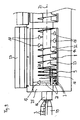
- FIGS. 1 to 4 showing a device 1 for cooling articles 3 according the invention in a perspective view and fig. 9 showing a detail of the device according to one of figures 1 to 4 will described together.
- the device 1 for cooling articles 3 comprises a rotatable cylinder 2 having tubular sections 1 made of a flexible material 4 such as woven polyester having a thickness of 2 mm.
- the tubular sections 12 form a wall 6 defining an inner space 5 in which the articles 3 are enclosed for cooling.
- the flexible material 4 forms the wall 6 such that the articles 3 are kept within the inner space 5 of the rotatable cylinder 2.
- Within the inner space 5 there is an Archimedian screw 8 which rotates together with the wall 6 and forms a conveyor means 10 with which the articles 3 are conveyed along a flow direction 7.
- the Archimedian screw 8 is tilted slightly with respect to the horizontal plane such that the articles 3 are moved uphill during operation of the Archimedian screw 8.
- the articles 3 are fed into an inlet port 16 of the rotating drum 2 by means of a vibrating trough 31.
- the articles 3 tumble down within each pocket of the Archimedean screw 8 due to gravity and are brought into contact with a cooling medium within the inner space 5 of the rotatable cylinder 2 such that they are cooled.
- the articles 3 are discharged through an outlet port 17 of the rotatable cylinder 2 for which purpose a rotary or "star" valve (not shown) is provided.
- the Archimedian screw 8 has an axis of rotation 24 which is tilted with respect to the horizontal plane.
- a cooling bath 18 is provided at the inlet port 16 of the rotatable cylinder 2 in which the articles 3 are immersed in a cryogenic liquid 28.
- the cryogenic liquid 28 is liquid nitrogen.
- the flexible material 4 comprises a multiplicity of pores 22 which are impregnated with the cryogenic liquid 28 such that the articles 3 are further cooled by thermal contact also in regions where the cooling bath 18 is not present.
- the pores 22 may be impregnated with cryogenic liquid 28 from the outside using spraying nozzles (not shown). Gas emerging from the cryogenic liquid 28 at the cooling bath 18 or from the pores 22 flows within the thread of the Archimedian screw 8 towards the outlet 17 of the Archimedean screw and may thus further cool the articles 3.
- the exhaust gas may exit through the exhaust 30.
- the device 1 comprises a casing 25 having a thermal insulation 26.
- the casing 26 may be closed using plural lids 27.
- the device 1 further comprises a cooling device 29 which provides for cryogenic liquid 28.
- the cooling device 29 may comprise supplying means 13 such as a spray header for feeding cryogenic liquid 28 to the cooling bath 18.
- the flexible material 4 may be fixed by means of screws 19, clips 20 or hooks and loops 21 to the rotatable cylinder 2.
- these fasteners 19, 20, 21 the tubular sections 12 of the wall 6 may be easily removed for cleaning.
- the tubular sections 12 are easily cleaned in a washer (not shown) separately.
- the ribbon screw 9 and the Archimedian screw 8 represent conveyor elements 14 with which the articles 3 are conveyed along the flow direction 7. Paddles 15 further effect mixing of the articles 3 for achieving homogeneous cooling.
- the Archimedian screw 8 comprises a central shaft 23 such that gas resulting from vaporization of the cryogenic liquid 28 is forced to follow the threads of the Archimedian screw 8 between the central shaft 23 and the wall 6 such that the velocity of the gas flow is increased and the cooling capacity and efficiency are further increased.
- the threads 23 together with the wall 6 and the central shaft 23 define a gas channel for the vaporized cryogenic liquid 28 such that the gas is forced through the articles 3 even if the inner space 5 of the rotatable cylinder 2 is filled to more than 20 % with the articles 3.
- the gas velocity is about 5 m/sec.
- the inner space 5 is filled to approximately 40 % with the articles 3.
- the articles 3 are mixed within the inner space 5 by means of the mixing elements 11.
- the length L of the drum is 8 m
- the diameter D of the drum is 1 m
- the diameter S of the central shaft 23 is 0,6 m
- the thickness of the flexible material 4 respectively of the wall 6 is 2 mm.
- FIGs 5 to 8 show perspective views of the Archimedian screw 8 according to figures 1 to 4 and 9.
- the Archimedian screw 8 comprises a central shaft 23 onto which the Archimedian threads 31 are formed.
- the Archimedian screw 8 rotates about the axis of rotation 24 defining the flow direction 7 of the articles 3.
- the Archimedian screw 8 is connected to a ribbon screw 9 which acts as mixing element 11 for mixing the articles 3 in the cooling bath 18.
- the ribbon screw 9 acts also as conveyor means 10 for conveying the articles 3 along the flow direction 7.
- the Archimedian screw 8 with the threads 31 and the central shaft 23 defines together with the wall 6 of the rotatable cylinder 2 a flow channel for the gas resulting from the vaporization of the cryogenic liquid 28 such that the relative velocity between the articles 3 and the gas is increased effecting an increased cooling efficiency.
- the invention concerns a device and a process for cooling articles 3 such as food, in particular meat, seafood, fruit or vegetables, with a rotatable cylinder 2 having an inner space 5 for receiving and cooling the articles 3, wherein the rotatable cylinder 2 comprises a wall 6 made of a flexible material 4 and the articles 3 are enclosed in the inner space 5 at least partially, wherein the flexible material 4 is at least one of fabric, tissue and canvas, in particular woven, preferably made from polyester, polyamide, in particular nylon, polyurethane and/or polyolefin; as well as articles cooled with the process respectively the device according to the invention.
- cryogenic liquid in particular liquid nitrogen or liquid carbon dioxide, or cryogenic solid such as carbon dioxide snow may be used.
Abstract
Description
- The invention concerns a process respectively an apparatus for cooling articles such as food, in particular meat, seafood, fruit or vegetables, wherein the articles are cooled within an inner space of a rotatable cylinder.
- In the field of cooling of material, in particular food products such as meat, seafood, fruit or vegetables, processes are known in which liquid nitrogen or liquid carbon dioxide are used as powerful refrigerating agents. Usually such processes involve the spraying of liquid nitrogen onto the products to be cooled, or the product is at least partially immersed in liquid nitrogen. Meanwhile very large volumes of gaseous nitrogen are formed due to the phase transition from the liquid into the gaseous state while cooling the product. Liquid nitrogen may be stored at 2 to 3 bar, using pressure transfer of the liquid to spray it onto the product to be cooled; the liquid obtains its latent heat of vaporisation from the product to convert it to gas at -196°C and this gas also provides a substantial source of cold (1,04 kJ/kg/°C) for further product cooling. In a similar way liquid carbon dioxide may be injected into devices operating at atmospheric pressure in which case the carbon dioxide becomes a mixture of solid carbon dioxide snow and gaseous carbon dioxide.
- According to
EP 0 632 966 a food article is frozen by contacting the article with a surface of a porous support which is impregnated with a cryogenic liquid, wherein the porous support may be formed as conveyor belt which is insulated by means of an enclosure. - It is known to use Archimedean screws for cooling of particular materials such as for cooling and freezing diced meat, seafood, fruit or vegetables, wherein the material is initially crust frozen by some means of contact with liquid nitrogen or a combination of solid and gaseous carbon dioxide generated by the depressurisation of liquid carbon dioxide so that the material becomes sufficiently stable to be removed by means of an Archimedean screw. It is advantageous (i) to effect as much heat transfer from the product to the gaseous nitrogen or carbon dioxide as possible, (ii) to introduce as little mechanical energy as possible, and (iii) to accept as little thermal losses as possible in order to achieve a high working efficiency.
- Systems using screw shaped elements rotating in a immobile tube or in a "U"-shaped trough are limited in their application as the product is pushed along the fixed tube, or respectively trough, such that the relative movement of the screw shaped elements and the tube, or respectively trough bear the risk of damaging the machinery and/or the product. Open trough constructions have the advantage of an easy access for simple cleaning. Closed screw designs have the inherent disadvantage to be hard to be cleaned. This is particularly disadvantageous for food use, which puts high demands on cleanness of the machinery and the product. Openable Archimedean screw structures may be engineered at small scale but larger units having more than 20 cm in diameter and more than 100 cm in length have proven to be unsatisfactory due to cleaning difficulties and/or ineffectiveness due to the differential thermal contraction when used at cryogenic temperature.
-
FR 2 613 900 - For large capacity systems, rotating tubes (rotary freezer) are known that are inclined downwards from the product inlet. The product moves the slope downwards due to tumbling caused by the rotation while it is being cooled by the cooling medium. Such systems have the advantage of a gentle movement action of the product. For the case that these rotating tubes may be constructed with a comparatively large internal diameter of more than 0.5 m and with a comparatively small length of less than 5 m, they can be made to be easily cleaned. However, these constructions may cause the product residence time in the system to vary much as the product residence time in the tube is not well defined and may vary depending upon the tumbling properties of the material being cooled. As some product articles may tumble much faster to the exit than others, the respective cooling treatments may vary from one article to the other considerably. For this reason, individual articles are cooled differently, in particular the critical point of phase transition about the freezing point is not well defined such that the kind of ice crystals formed in the product differs from one article to the other, which causes the product homogeneity to vary. Moreover the heat capacity of the cold gas may not be efficiently used in such systems for cooling the product. In consequence, besides product homogeneity and product quality, the degree of thermodynamic efficiency is reduced.
- The object of the present invention is to provide for a process respectively device for cooling articles such as food, in particular meat, seafood, fruit or vegetables, with which the articles may be cooled homogenously on a large scale with a high efficiency at a food grade standard.
- This problem is solved by the process for cooling articles respectively by the device for cooling articles as defined in the independent claims. Advantageous embodiments and favourable developments, which can be applied individually or can be combined in any suitable manner, are subject of the respective depending claims.
- According to the invention the process for cooling articles such as food, in particular meat, seafood, fruit or vegetables, wherein the articles are cooled within an inner space of a rotatable cylinder comprising a wall made of a flexible material and the articles being enclosed in the inner space at least partially, the flexible material is at least one of fabric, tissue and canvas, in particular woven, preferably made from polyester, polyamide (in particular aromatic polyamide such as produced under the trademarks Kevlar or Nomex), in particular nylon, polyurethane and/or polyolefin.
- The flexible material may be the one as described in
WO 93/14358 - By the use of the rotatable cylinder the articles simply tumble and move due to the force of gravity as the drum rotates and the articles thus travel along the rotatable cylinder with no risk of becoming trapped against or between elements of the construction that are moving relative to each other, this design is effecting a much gentler action for the articles reducing damage to the articles due to their movement. The rotatable cylinder may be a rotable drum.
- The flexible material is preferably food grade, in particular is not toxic or harmful with regard to food articles for human consumption.
- By means of the flexible material comparatively large rotatable cylinders may be constructed, e.g. drums having a diameter of more than 0.5 m and a length of more than 5 m, that are easy to be cleaned despite of their largeness. For cleaning purposes the flexible material may be removably fixed to the rotatable cylinder, thus may be cleaned separately. In operation the flexible material is fixed to the rotatable cylinder and rotates therewith.
- The flexible material may be wrapped in segments or in full revolutions around the rotatable cylinder providing a highly effective outer wall. The flexible material may be designed to be light weight, easy to handle and easy to be cleaned even for food grade standards. It is advantageous to use woven polyester as it is capable of adsorbing and retaining a cooling medium such as liquid nitrogen. The flexible material may absorb and become impregnated with the cooling medium for providing a source of additional cooling to the articles by means of thermal contact of the articles with the flexible material as the articles tumble. For some applications it may be advantageous to include a specific spraying means for the cooling medium to the outside of the material in order to create an impregnation from outside.
- The flexible material may be fixed to the rotatable cylinder, using a means that allows it to be easily removed, in particular by means of clamping, hooking, and/or clipping. The flexible material may be wrapped as one piece around the rotatable cylinder or may be fixed as patches onto the drum. The flexible material may also be fixed by screwing.
- The articles may be cooled using a cryogenic liquid or a cryogenic solid. The cryogenic liquid may be liquid nitrogen or liquid carbon dioxide. The cryogenic solid may be carbon dioxide snow. Gaseous fluid may also be used for cooling. The gaseous or liquid respectively solid carbon dioxide may produced by depressurising liquid carbon dioxide.
- The flexible material may be impregnated with the cryogenic liquid and heat transfer between the articles and the cryogenic liquid within the flexible material may be ensured. By impregnating the flexible material with cryogenic liquid and bringing the articles into contact with the flexible material, a close thermal contact between the articles and the cryogenic liquid is achieved without using a cooling bath such that a high cooling capacity is achieved without the need of providing for a bath container. For even higher cooling capacity at least a partial length of the cylinder may incorporate a liquid nitrogen immersion section.
- The articles may be conveyed along a flow direction in the drum with a conveyor means, in particular may be conveyed along the flow direction using an Archimedian screw and/or a ribbon screw. The flexible material may be fixed to the conveyor means in the sense that the rotatable cylinder with the flexible material is fixed to the screw and rotates therewith. The articles may also be conveyed using individual screw segments such as paddles.
- The articles may be conveyed upwards or downwards along a slope with an inclination with respect to the horizontal plane in the range of -45° to +45°, preferably in the range of 0° to +6°.
- By means of using the conveyor means, an easy separation of the articles from a cooling bath at an inlet of the rotatable cylinder may be achieved. For example, the Archimedean screw comprises an inner shaft onto which a screw thread is formed. The ribbon screw may have an open cross section along the axis of rotation of the screw. The function of the ribbon screw may be mixing the articles, conveying the articles or both.
- The articles may be mixed using mixing elements. The mixing elements help to reduce thermal inhomogeneities among the articles, which helps to provide for well defined cooling conditions for all articles.
- Thermal problems arsing from incomplete mixing of the articles may be also overcome using one or more bars or blades fixed over some of the length of the screw, or by adding mixing blades to the screw element. The function of such devices is to lift articles from the bottom of a pocket of the Archimedean screw further up the side of the wall of the rotatable cylinder so that the articles fall to the top of the pocket such, that the articles are effectively mixed in the device as they are transported to the outlet, thus creating more even and effective cooling.
- For articles that are not very porous the pockets of the screw may be filled approximately half to three quarter relative to the volume of material that would completely fill the pockets created by the screw. This helps to increase the velocity of gas flow. The velocity of the gas flow within the rotatable cylinder is in particular ranging from 2 m/sec to 20 m/sec, typically around 5m/sec. By means of such high flow velocities, the heat transfer from product to gas is observed to be two to four times higher than that achieved in the equivalent element of the "Rotary Freezer" described previously in the prior art. It may be advantageous to seal the cooling unit such that the gas evolving from the boiling cooling medium can exit the system only through the outlet of the rotatable cylinder respectively Archimedean screw. The cooled articles may be separated from the gaseous cooling medium using sieves or cyclone type separators, the separation being assisted by the use of a rotary valve to limit the gas exiting with the product. As the Archimedes screw is inherently a low energy demanding device, a typical unit will require a drive motor that is much less powerful than that required for a conveyor belt used in cryogenic tunnels of equivalent conveying capacity. By using a variable speed drive it is simple to adjust the speed to match the filling of the unit with the production and cooling capacities required.
- The articles may be frozen at least partially. For example the device provides for freezing only an outer shell of the articles, the inside of the articles remaining above freezing point at least for the duration of their presence in the device.
- According to the invention the device for cooling articles such as food, in particular meat, seafood, fruit or vegetables, comprises a rotatable cylinder having an inner space for receiving and cooling the articles, wherein the rotatable cylinder comprises a wall made of a flexible material and the articles are enclosed in the inner space at least partially, wherein the flexible material is at least one of fabric, tissue and canvas, in particular woven, preferably made from polyester, polyamide, in particular nylon, polyurethane and/or polyolefin.
- The flexible material may be formed as sheets or patches or as integral part and may be attached to or wrapped around the rotatable cylinder. The flexible material may be fixed onto the circumference of the drum or may be fixed at the drum. The flexible material may be removably fixed to the rotatable cylinder in particular by means of clamping, hooking and/or clipping. For this purpose the drum respectively the flexible material may comprise clamps, hooks, clips, loops or screws.
- The device may further comprise a cooling device for cooling the articles, in particular supplying means for supplying cryogenic liquid, in particular liquid nitrogen.
- The flexible material may be advantageously porous and impregnatable with the cryogenic liquid. For this purpose the flexible material may be either woven, knitted or perforated. The flexible material may comprise a multiplicity of protrusions or brush shaped elements that are able to carry cryogenic liquid. The flexible material may be the one as defined in
WO 93/14358 - The wall may comprise tubular sections, wherein the tubular sections are at least partially made of the flexible material.
- The rotatable cylinder may comprise in its inner space conveyor means for conveying the articles along a flow direction. The conveying means may comprise an Archimedian screw and/or a ribbon screw, in particular with an inclination with respect to the horizontal plane in the range of -45° to +45°, preferably in the range of 0° to 6°. The inclination may be uphill or downhill, such that the articles are conveyed against gravity from a lower vertical position to a higher vertical position, or with gravity from a higher to lower position.
- The device may comprise a cooling bath, in particular a cooling bath that may contain liquid nitrogen. By means of the conveyor means the articles may be taken out of the cooling bath and moved uphill such that the articles are separated from the cooling medium in the cooling bath. The rotatable cylinder may comprise an inlet port and an outlet port and the inlet port may be at least partially immersed in a cooling bath.
- The conveyor means may comprise conveyor elements or mixing elements in particular paddles. The conveyor elements provide for a particularly uniform temperature distribution and thus provide for well defined cooling conditions which help to meet uniform product specifications.
- The flexible material may be removably fixed at the drum, in particular by means of screws, clips and/or hooks and loops or by clamping. Screws, clips and/or hooks or loops respectively clamping helps to easily remove the flexible material for separate cleaning.
- The device may further comprise at least one of the following features a1) to a5): (a1) the drum has a length ranging from 1 m to 10 m in particular ranging from 2 m to 6 m; (a2) the drum has a diameter (D) ranging from 0,4m to 3m, in particular ranging from 0.8 m to 2 m: (a3) the drum has a central shaft extending at least partially over the length (L) or the drum along the axis of rotation of the drum, the diameter (S) of the central shaft ranging from 10 % to 70 %, in particular ranging from 30 % to 50 %, of the diameter (D) of the drum; (a4) the flexible material has pores having average diameters ranging from 0,001 to 5 mm; (a5) the flexible material has a thickness (F) ranging from 0,5 mm to 5 mm, in particular ranging from 2 mm to 4 mm.
- The device may further comprise a casing, in particular a casing with a thermal insulation preferably having openable lids, around the rotatable cylinder.
- According to the invention, the articles, in particular chilled or frozen goods, in particular food such as meat, seafood, fruit or vegetables, is cooled with the process and/or cooled with the device according to the invention. Such articles profit from the easy cleanability of the device respectively the efficient and homogeneous cooling conditions under which they are cooled. Due to the efficient and homogenous cooling conditions, the goods meet high quality standards at high product homogeneity.
- Further advantageous details and favourable aspects of the invention, which may be applied individually or may be combined with one another in every suitable way, will be explained in connection with the accompanying drawings, which shall not limit the scope of the invention but merely illustrate exemplarily the invention.
- In the following, schematically,
- figures 1 to 4
- show the device for cooling articles according to the invention in a perspective view;
- figures 5 to 8
- show various (details of) embodiments of a screw of the device according to fig. 1 to 4 in a perspective view; and
- figure 9
- shows a detail of device according to one of figures 1 to 4.
- Figures 1 to 4 showing a device 1 for cooling
articles 3 according the invention in a perspective view and fig. 9 showing a detail of the device according to one of figures 1 to 4 will described together. - The device 1 for cooling
articles 3 comprises arotatable cylinder 2 having tubular sections 1 made of a flexible material 4 such as woven polyester having a thickness of 2 mm. Thetubular sections 12 form a wall 6 defining aninner space 5 in which thearticles 3 are enclosed for cooling. The flexible material 4 forms the wall 6 such that thearticles 3 are kept within theinner space 5 of therotatable cylinder 2. Within theinner space 5 there is anArchimedian screw 8 which rotates together with the wall 6 and forms a conveyor means 10 with which thearticles 3 are conveyed along a flow direction 7. TheArchimedian screw 8 is tilted slightly with respect to the horizontal plane such that thearticles 3 are moved uphill during operation of theArchimedian screw 8. Thearticles 3 are fed into aninlet port 16 of therotating drum 2 by means of a vibratingtrough 31. Thearticles 3 tumble down within each pocket of theArchimedean screw 8 due to gravity and are brought into contact with a cooling medium within theinner space 5 of therotatable cylinder 2 such that they are cooled. Thearticles 3 are discharged through anoutlet port 17 of therotatable cylinder 2 for which purpose a rotary or "star" valve (not shown) is provided. TheArchimedian screw 8 has an axis ofrotation 24 which is tilted with respect to the horizontal plane. At theinlet port 16 of the rotatable cylinder 2 a coolingbath 18 is provided in which thearticles 3 are immersed in acryogenic liquid 28. Thecryogenic liquid 28 is liquid nitrogen. The flexible material 4 comprises a multiplicity ofpores 22 which are impregnated with thecryogenic liquid 28 such that thearticles 3 are further cooled by thermal contact also in regions where the coolingbath 18 is not present. Thepores 22 may be impregnated with cryogenic liquid 28 from the outside using spraying nozzles (not shown). Gas emerging from thecryogenic liquid 28 at the coolingbath 18 or from thepores 22 flows within the thread of theArchimedian screw 8 towards theoutlet 17 of the Archimedean screw and may thus further cool thearticles 3. The exhaust gas may exit through theexhaust 30. The device 1 comprises acasing 25 having athermal insulation 26. Thecasing 26 may be closed usingplural lids 27. The device 1 further comprises acooling device 29 which provides forcryogenic liquid 28. Thecooling device 29 may comprise supplyingmeans 13 such as a spray header for feedingcryogenic liquid 28 to the coolingbath 18. The flexible material 4 may be fixed by means of screws 19, clips 20 or hooks andloops 21 to therotatable cylinder 2. By means of thesefasteners tubular sections 12 of the wall 6 may be easily removed for cleaning. Thetubular sections 12 are easily cleaned in a washer (not shown) separately. Within theinner space 5 of therotatable cylinder 2 there is aribbon screw 9 which takes thearticles 3 out of the coolingbath 18. Theribbon screw 9 and theArchimedian screw 8 representconveyor elements 14 with which thearticles 3 are conveyed along the flow direction 7.Paddles 15 further effect mixing of thearticles 3 for achieving homogeneous cooling. TheArchimedian screw 8 comprises acentral shaft 23 such that gas resulting from vaporization of thecryogenic liquid 28 is forced to follow the threads of theArchimedian screw 8 between thecentral shaft 23 and the wall 6 such that the velocity of the gas flow is increased and the cooling capacity and efficiency are further increased. Thethreads 23 together with the wall 6 and thecentral shaft 23 define a gas channel for the vaporizedcryogenic liquid 28 such that the gas is forced through thearticles 3 even if theinner space 5 of therotatable cylinder 2 is filled to more than 20 % with thearticles 3. The gas velocity is about 5 m/sec. Theinner space 5 is filled to approximately 40 % with thearticles 3. Thearticles 3 are mixed within theinner space 5 by means of the mixing elements 11. The length L of the drum is 8 m, the diameter D of the drum is 1 m, the diameter S of thecentral shaft 23 is 0,6 m and the thickness of the flexible material 4 respectively of the wall 6 is 2 mm. - Figures 5 to 8 show perspective views of the
Archimedian screw 8 according to figures 1 to 4 and 9. TheArchimedian screw 8 comprises acentral shaft 23 onto which theArchimedian threads 31 are formed. TheArchimedian screw 8 rotates about the axis ofrotation 24 defining the flow direction 7 of thearticles 3. TheArchimedian screw 8 is connected to aribbon screw 9 which acts as mixing element 11 for mixing thearticles 3 in the coolingbath 18. Theribbon screw 9 acts also as conveyor means 10 for conveying thearticles 3 along the flow direction 7. TheArchimedian screw 8 with thethreads 31 and thecentral shaft 23 defines together with the wall 6 of the rotatable cylinder 2 a flow channel for the gas resulting from the vaporization of thecryogenic liquid 28 such that the relative velocity between thearticles 3 and the gas is increased effecting an increased cooling efficiency. - The invention concerns a device and a process for cooling
articles 3 such as food, in particular meat, seafood, fruit or vegetables, with arotatable cylinder 2 having aninner space 5 for receiving and cooling thearticles 3, wherein therotatable cylinder 2 comprises a wall 6 made of a flexible material 4 and thearticles 3 are enclosed in theinner space 5 at least partially, wherein the flexible material 4 is at least one of fabric, tissue and canvas, in particular woven, preferably made from polyester, polyamide, in particular nylon, polyurethane and/or polyolefin; as well as articles cooled with the process respectively the device according to the invention. The use of the flexible material allows for simple cleaning of the cooling device even if largerotatable cylinder 2 are involved that comprise anArchimedian screw 8 in their inner space 4, thus allowing for homogeneous, clean and efficient cooling of thearticles 3. As cooling medium cryogenic liquid, in particular liquid nitrogen or liquid carbon dioxide, or cryogenic solid such as carbon dioxide snow may be used. -
- 1
- Device
- 2
- drum
- 3
- articles
- 4
- material
- 5
- space
- 6
- wall
- 7
- flow direction
- 8
- Archimedean screw
- 9
- ribbon screw
- 10
- conveyor means
- 11
- mixing elements
- 12
- tubular sections
- 13
- supplying means
- 14
- conveyor elements
- 15
- paddles
- 16
- inlet port
- 17
- outlet port
- 18
- cooling bath
- 19
- screw
- 20
- clips
- 21
- hooks and loops
- 22
- pores
- 23
- central shaft
- 24
- axis of rotation
- 25
- casing
- 26
- thermal insulation
- 27
- lid
- 28
- cryogenic liquid
- 29
- cooling device
- 30
- exhaust
- 31
- vibrating trough
- 32
- thread
- L
- length of the drum
- D
- diameter of the drum
- S
- diameter of
central shaft 23
Claims (19)
- Process for cooling articles (3) such as food, in particular meat, seafood, fruit or vegetables, wherein the articles (3) are cooled within an inner space (5) of a rotatable cylinder (2), the rotatable cylinder (2) comprising a wall (6) made of a flexible material (4) and the articles (3) being enclosed in the inner space (5) at least partially,
characterized in that
the flexible material (4) is at least one of fabric, tissue and canvas, in particular woven, preferably made from polyester, polyamide, aromatic polyamide, in particular Nylon, polyurethane and/or polyolefin. - Process according to claim 1, characterized in that the flexible material (4) is removably fixed to the rotatable cylinder, in particular by means of clamping, hooking and/or clipping.
- Process according to claim 1 or 2, characterized in that the articles (3) are cooled using a cryogenic liquid (28) or a cryogenic solid such as solid carbon dioxide produced by depressurising liquid carbon dioxide.
- Process according to claim 3, characterized in that the flexible material (4) is impregnated with the cryogenic liquid (28) and heat transfer between the articles (3) and the cryogenic liquid (28) within the flexible material (4) is ensured.
- Process according to one of the preceding claims, characterized in that the articles (3) are conveyed along a flow direction (7) in the drum (2) with conveyor means (10), in particular is conveyed along the flow direction (7) using an Archimedean screw (8) and/or a ribbon screw (9).
- Process according to one of the preceding claims, characterized in that the articles (3) are mixed using mixing elements (11).
- Process according to one of the preceding claims, characterized in that the articles (3) are frozen at least partially.
- Device (1) for cooling articles (3) such as food, in particular meat, seafood, fruit or vegetables, comprising a rotatable cylinder (2) having an inner space (5) for receiving and cooling the articles (3), wherein the rotatable cylinder (2) comprises a wall (6) made of a flexible material (4) and the articles (3) are enclosed in the inner space (5) at least partially,
characterized in that
the flexible material (4) is at least one of fabric, tissue and canvas, in particular woven, preferably made from polyester, polyamide, aromatic polyamide, in particular Nylon, polyurethane and/or polyolefin. - Device (1) according to claim 8, characterized in that the flexible material (4) is the flexible material (4) is removably fixed at the drum (2), in particular by means of screws (19), clips (20) and/or hooks and loops (21) or by clamping.
- Device (1) according to claim 8 or 9, further comprising a cooling device (29) for cooling the articles (3), in particular supplying means (13) for supplying cryogenic liquid (28), in particular liquid nitrogen, and liquid carbon dioxide for cooling the articles (3).
- Device (1) according to claim 10, characterized in that the flexible material (4) is porous and is impregnatable with the cryogenic liquid (28).
- Device (1) according to one of the preceding claims 8 to 11, characterized in that the wall (6) comprises tubular sections (12), wherein the tubular sections (12) are at least partially made of the flexible material (4).
- Device (1) according to one of the preceding claims 8 to 12, characterized in that the rotatable cylinder (2) comprises in its inner space (5) conveyor means (10) for conveying the articles (3) along a flow direction (7).
- Device (1) according to claim 13, characterized in that conveyor means (10) comprises an Archimedean screw (8) and/or a ribbon screw (9), in particular with an inclination with respect to the horizontal plane in the range of -45° to +45°, preferably in the range of 0° to 6°.
- Device (1) according to claim 13 or 14, characterized in that the conveyor means (10) comprises conveyor elements (14) or mixing elements (11), in particular paddles (15).
- Device (1) according to one of the preceding claims 8 to 15, characterized in that the rotatable cylinder (2) has an inlet port (16) and an outlet port (17) and the inlet port (16) is at least partially immersed in a cooling bath (18).
- Device (1) according to one of the preceding claims 8 to 17, further comprising at least one of the following features (a1) to (a5):(a1) The drum (2) has a length (L) ranging from 1 m to 10 m, in particular ranging from 2 m to 6 m;(a2) the drum (2) has a diameter (D) ranging from 0,4m to 3m, in particular ranging from 0.8 m to 2m;(a3) the drum (2) has a central shaft (23) extending at least partially over the length (L) or the drum (2) along the axis of rotation (24) of the drum (2), the diameter (S) of the central shaft (23) ranging from 10 % to 70 %, in particular ranging from 30% to 50%, of the diameter (D) of the drum (2);(a4) the flexible material (4) has pores (22) having average diameters ranging from 0,001 to 5 mm;(a5) the flexible material (4) has a thickness (F) ranging from 0,5 mm to 5 mm, in particular ranging from 1 mm to 3 mm.
- Device (1) according to one of the preceding claims 8 to 17, further comprising a casing (25), in particular a casing (25) with a thermal insulation (26), preferably having openable lids (27), around the rotatable cylinder.
- Articles (3), in particular chilled or frozen goods, in particular food such as meat, seafood, fruit or vegetables, cooled with a process according to one of claims 1 to 7 and/or cooled using a device (1) according to one of claims 8 to 18.
Priority Applications (5)
| Application Number | Priority Date | Filing Date | Title |
|---|---|---|---|
| DE602005013792T DE602005013792D1 (en) | 2005-11-15 | 2005-11-15 | Method and device for cooling food |
| EP05300923A EP1785043B1 (en) | 2005-11-15 | 2005-11-15 | Process and device for cooling food articles |
| AT05300923T ATE427667T1 (en) | 2005-11-15 | 2005-11-15 | METHOD AND APPARATUS FOR COOLING FOOD |
| PCT/EP2006/068212 WO2007057330A1 (en) | 2005-11-15 | 2006-11-08 | Process and device for cooling food articles |
| US12/093,841 US20080274250A1 (en) | 2005-11-15 | 2006-11-08 | Process and Device for Cooling Food Articles |
Applications Claiming Priority (1)
| Application Number | Priority Date | Filing Date | Title |
|---|---|---|---|
| EP05300923A EP1785043B1 (en) | 2005-11-15 | 2005-11-15 | Process and device for cooling food articles |
Publications (2)
| Publication Number | Publication Date |
|---|---|
| EP1785043A1 true EP1785043A1 (en) | 2007-05-16 |
| EP1785043B1 EP1785043B1 (en) | 2009-04-08 |
Family
ID=35998408
Family Applications (1)
| Application Number | Title | Priority Date | Filing Date |
|---|---|---|---|
| EP05300923A Active EP1785043B1 (en) | 2005-11-15 | 2005-11-15 | Process and device for cooling food articles |
Country Status (5)
| Country | Link |
|---|---|
| US (1) | US20080274250A1 (en) |
| EP (1) | EP1785043B1 (en) |
| AT (1) | ATE427667T1 (en) |
| DE (1) | DE602005013792D1 (en) |
| WO (1) | WO2007057330A1 (en) |
Cited By (5)
| Publication number | Priority date | Publication date | Assignee | Title |
|---|---|---|---|---|
| ES2337649A1 (en) * | 2008-05-30 | 2010-04-27 | Ziritrone, S.A. | Procedure for conservation of fruits or vegetables. (Machine-translation by Google Translate, not legally binding) |
| WO2011047983A3 (en) * | 2009-10-22 | 2011-06-16 | L'air Liquide Societe Anonyme Pour L'etude Et L'exploitation Des Procedes Georges Claude | Process and device for freezing goods to be frozen |
| WO2014197950A1 (en) * | 2013-06-12 | 2014-12-18 | Xinir Bvba | Method for preparing deep-frozen vegetables pieces |
| DE102018102702B3 (en) | 2018-02-07 | 2019-02-28 | Carlos Alberto Ramos Diogo | Conditioning device for the continuous treatment of solid food and feed and other bulk materials after a heat treatment |
| WO2021188302A1 (en) * | 2020-03-16 | 2021-09-23 | Praxair Technology, Inc. | System for cooling non-liquid conveyable product |
Families Citing this family (3)
| Publication number | Priority date | Publication date | Assignee | Title |
|---|---|---|---|---|
| RU2649623C2 (en) * | 2013-01-29 | 2018-04-04 | Джозеф Компани Интернэшнл, Инк. | Carbon dioxide charging apparatus and method for heat exchange device |
| PE20170214A1 (en) * | 2014-04-11 | 2017-04-05 | Naturo All Natural Tech Pty Ltd | PROCESS, APPARATUS AND SYSTEM TO TREAT FRUITS OR VEGETABLES |
| CN113203234B (en) * | 2021-05-07 | 2023-04-14 | 禹豪(浙江)食品有限公司 | Precooling apparatus for food production |
Citations (6)
| Publication number | Priority date | Publication date | Assignee | Title |
|---|---|---|---|---|
| FR2613900A1 (en) * | 1987-04-15 | 1988-10-21 | Corberon Rene | Archimedes screw with flexible bottomed trough for processing and handling fragile seeds |
| US5363658A (en) * | 1993-07-09 | 1994-11-15 | The Boc Group, Inc. | Apparatus and process for chilling food products |
| US5454232A (en) * | 1992-01-21 | 1995-10-03 | L'air Liquide, Societe Anonyme Pour L'etude Et L'exploitation Des Procedes Georges Claude | Freezing process and device |
| EP0863373A2 (en) * | 1997-03-04 | 1998-09-09 | L'air Liquide, Societe Anonyme Pour L'etude Et L'exploitation Des Procedes Georges Claude | Multitier crossflow cryogenic freezer and method of use |
| US5857352A (en) * | 1996-10-24 | 1999-01-12 | Winterlab Limited | Ribbon-freezing method and apparatus |
| US6167708B1 (en) * | 1998-09-14 | 2001-01-02 | L'aire Liquide, Societe Anonyme Pour L'etude Et L'exploitation Des Procedes Georges Claude | Process and apparatus for the in-line freezing of products |
Family Cites Families (15)
| Publication number | Priority date | Publication date | Assignee | Title |
|---|---|---|---|---|
| US1714235A (en) * | 1928-09-07 | 1929-05-21 | Orton A Peck | Milk cooler |
| US4137723A (en) * | 1977-09-07 | 1979-02-06 | Lewis Tyree Jr | Direct contact CO2 cooling |
| GB8800937D0 (en) * | 1988-01-15 | 1988-02-17 | Kedgwick Ltd | Improvements relating to processing of denim garments |
| US5358727A (en) * | 1993-03-01 | 1994-10-25 | Sunsweet Growers, Inc. | Method for producing molded food pieces |
| US5407809A (en) * | 1993-06-07 | 1995-04-18 | Bedminster Bioconversion Corporation | Digester for converting organic material into compost |
| US5329842A (en) * | 1993-09-15 | 1994-07-19 | Lyco Manufacturing, Inc. | Combination blancher and cooler |
| US5427015A (en) * | 1993-09-15 | 1995-06-27 | Lyco Manufacturing, Inc. | Drum with exterior frame for blanchers and coolers |
| US5603567A (en) * | 1995-02-17 | 1997-02-18 | Blentech Corporation | Coaxial cryogenic injection system |
| US5669288A (en) * | 1996-03-29 | 1997-09-23 | Lyco Manufacturing, Inc. | Rotating drum food processor with cleaning spray accessible panels |
| GB9722986D0 (en) * | 1997-10-30 | 1998-01-07 | Boc Group Plc | Tumble coating |
| US6214400B1 (en) * | 1999-10-14 | 2001-04-10 | Lyco Manufacturing Inc. | Method for processing food product |
| US6817284B2 (en) * | 2002-06-14 | 2004-11-16 | Lyco Manufacturing, Inc. | Food processing apparatus, transport mechanism, bucket and method |
| US7228793B2 (en) * | 2002-11-25 | 2007-06-12 | Fizzy Fruit, LLC | Carbonation system for enhancing the flavor of fruits and vegetables |
| US7181886B2 (en) * | 2003-05-12 | 2007-02-27 | Eric Bourgoin | Orbital hydroponic or aeroponic agricultural unit |
| US6708603B1 (en) * | 2003-06-30 | 2004-03-23 | Lyu Jan Co., Ltd. | Frying pot |
-
2005
- 2005-11-15 DE DE602005013792T patent/DE602005013792D1/en active Active
- 2005-11-15 AT AT05300923T patent/ATE427667T1/en not_active IP Right Cessation
- 2005-11-15 EP EP05300923A patent/EP1785043B1/en active Active
-
2006
- 2006-11-08 US US12/093,841 patent/US20080274250A1/en not_active Abandoned
- 2006-11-08 WO PCT/EP2006/068212 patent/WO2007057330A1/en active Application Filing
Patent Citations (6)
| Publication number | Priority date | Publication date | Assignee | Title |
|---|---|---|---|---|
| FR2613900A1 (en) * | 1987-04-15 | 1988-10-21 | Corberon Rene | Archimedes screw with flexible bottomed trough for processing and handling fragile seeds |
| US5454232A (en) * | 1992-01-21 | 1995-10-03 | L'air Liquide, Societe Anonyme Pour L'etude Et L'exploitation Des Procedes Georges Claude | Freezing process and device |
| US5363658A (en) * | 1993-07-09 | 1994-11-15 | The Boc Group, Inc. | Apparatus and process for chilling food products |
| US5857352A (en) * | 1996-10-24 | 1999-01-12 | Winterlab Limited | Ribbon-freezing method and apparatus |
| EP0863373A2 (en) * | 1997-03-04 | 1998-09-09 | L'air Liquide, Societe Anonyme Pour L'etude Et L'exploitation Des Procedes Georges Claude | Multitier crossflow cryogenic freezer and method of use |
| US6167708B1 (en) * | 1998-09-14 | 2001-01-02 | L'aire Liquide, Societe Anonyme Pour L'etude Et L'exploitation Des Procedes Georges Claude | Process and apparatus for the in-line freezing of products |
Cited By (8)
| Publication number | Priority date | Publication date | Assignee | Title |
|---|---|---|---|---|
| ES2337649A1 (en) * | 2008-05-30 | 2010-04-27 | Ziritrone, S.A. | Procedure for conservation of fruits or vegetables. (Machine-translation by Google Translate, not legally binding) |
| WO2011047983A3 (en) * | 2009-10-22 | 2011-06-16 | L'air Liquide Societe Anonyme Pour L'etude Et L'exploitation Des Procedes Georges Claude | Process and device for freezing goods to be frozen |
| WO2014197950A1 (en) * | 2013-06-12 | 2014-12-18 | Xinir Bvba | Method for preparing deep-frozen vegetables pieces |
| BE1022060B1 (en) * | 2013-06-12 | 2016-02-11 | Xinir Bvba | METHOD FOR MANUFACTURING FROZEN PIECES OF VEGETABLES |
| RU2654795C2 (en) * | 2013-06-12 | 2018-05-22 | Ксинир Бвба | Method for preparing deep-frozen vegetable pieces |
| US10398152B2 (en) | 2013-06-12 | 2019-09-03 | Xinir Bvba | Method for preparing deep-frozen vegetables pieces |
| DE102018102702B3 (en) | 2018-02-07 | 2019-02-28 | Carlos Alberto Ramos Diogo | Conditioning device for the continuous treatment of solid food and feed and other bulk materials after a heat treatment |
| WO2021188302A1 (en) * | 2020-03-16 | 2021-09-23 | Praxair Technology, Inc. | System for cooling non-liquid conveyable product |
Also Published As
| Publication number | Publication date |
|---|---|
| DE602005013792D1 (en) | 2009-05-20 |
| WO2007057330A1 (en) | 2007-05-24 |
| EP1785043B1 (en) | 2009-04-08 |
| US20080274250A1 (en) | 2008-11-06 |
| ATE427667T1 (en) | 2009-04-15 |
Similar Documents
| Publication | Publication Date | Title |
|---|---|---|
| EP1785043B1 (en) | Process and device for cooling food articles | |
| AU664238B2 (en) | Freezing method and device | |
| JP4257200B2 (en) | Device for massaging products | |
| EP0250381B1 (en) | Process and apparatus for freezing liquid or semiliquid foods in the form of essentially uniform pellets | |
| US3213634A (en) | Method and apparatus for individual quick freezing | |
| EP2145846B1 (en) | Transfer mechanism for use with a food processing system | |
| US5765381A (en) | Multitier crossflow cryogenic freezer and method of use | |
| US6334330B2 (en) | Impingement cooler | |
| WO1996000875A1 (en) | Apparatus and methods for cryogenic treatment of materials | |
| US3446030A (en) | Method and apparatus for quick freezing individual food items | |
| US5606861A (en) | Crossflow cryogenic freezer and method of use | |
| CA2280199C (en) | Impingement cooler | |
| US5857352A (en) | Ribbon-freezing method and apparatus | |
| JPH02183784A (en) | Tunnel type refrigerating machine | |
| AU715465B2 (en) | Cooling apparatus | |
| CA2053976C (en) | Refrigeration apparatus and method of refrigeration | |
| US5156006A (en) | Apparatus for cooling a heat transfer fluid | |
| EP2405762A1 (en) | Freezer and freezing method | |
| JPH0134065Y2 (en) | ||
| EP0918473B1 (en) | Continuous deep freeze chamber with tiered-up refrigerated tables | |
| GB2023789A (en) | Method and apparatus for cooling or freezing | |
| ES2958565T3 (en) | System and method for processing food products by at least partial freezing or refrigeration | |
| EP0671130A1 (en) | Apparatus for freezing or deep-freezing food products | |
| CA3171053A1 (en) | System for cooling non-liquid conveyable product | |
| WO2023140987A1 (en) | Apparatus and method for crust freezing |
Legal Events
| Date | Code | Title | Description |
|---|---|---|---|
| PUAI | Public reference made under article 153(3) epc to a published international application that has entered the european phase |
Free format text: ORIGINAL CODE: 0009012 |
|
| AK | Designated contracting states |
Kind code of ref document: A1 Designated state(s): AT BE BG CH CY CZ DE DK EE ES FI FR GB GR HU IE IS IT LI LT LU LV MC NL PL PT RO SE SI SK TR |
|
| AX | Request for extension of the european patent |
Extension state: AL BA HR MK YU |
|
| RAP1 | Party data changed (applicant data changed or rights of an application transferred) |
Owner name: L'AIR LIQUIDE, SOCIETE ANONYME POUR L'ETUDE ET L'E Owner name: AIR LIQUIDE DEUTSCHLAND GMBH |
|
| 17P | Request for examination filed |
Effective date: 20071116 |
|
| AKX | Designation fees paid |
Designated state(s): AT BE BG CH CY CZ DE DK EE ES FI FR GB GR HU IE IS IT LI LT LU LV MC NL PL PT RO SE SI SK TR |
|
| 17Q | First examination report despatched |
Effective date: 20080115 |
|
| GRAP | Despatch of communication of intention to grant a patent |
Free format text: ORIGINAL CODE: EPIDOSNIGR1 |
|
| GRAP | Despatch of communication of intention to grant a patent |
Free format text: ORIGINAL CODE: EPIDOSNIGR1 |
|
| GRAS | Grant fee paid |
Free format text: ORIGINAL CODE: EPIDOSNIGR3 |
|
| GRAA | (expected) grant |
Free format text: ORIGINAL CODE: 0009210 |
|
| AK | Designated contracting states |
Kind code of ref document: B1 Designated state(s): AT BE BG CH CY CZ DE DK EE ES FI FR GB GR HU IE IS IT LI LT LU LV MC NL PL PT RO SE SI SK TR |
|
| REG | Reference to a national code |
Ref country code: GB Ref legal event code: FG4D |
|
| REG | Reference to a national code |
Ref country code: CH Ref legal event code: EP |
|
| REG | Reference to a national code |
Ref country code: IE Ref legal event code: FG4D |
|
| REF | Corresponds to: |
Ref document number: 602005013792 Country of ref document: DE Date of ref document: 20090520 Kind code of ref document: P |
|
| PG25 | Lapsed in a contracting state [announced via postgrant information from national office to epo] |
Ref country code: SI Free format text: LAPSE BECAUSE OF FAILURE TO SUBMIT A TRANSLATION OF THE DESCRIPTION OR TO PAY THE FEE WITHIN THE PRESCRIBED TIME-LIMIT Effective date: 20090408 |
|
| PG25 | Lapsed in a contracting state [announced via postgrant information from national office to epo] |
Ref country code: ES Free format text: LAPSE BECAUSE OF FAILURE TO SUBMIT A TRANSLATION OF THE DESCRIPTION OR TO PAY THE FEE WITHIN THE PRESCRIBED TIME-LIMIT Effective date: 20090719 Ref country code: FI Free format text: LAPSE BECAUSE OF FAILURE TO SUBMIT A TRANSLATION OF THE DESCRIPTION OR TO PAY THE FEE WITHIN THE PRESCRIBED TIME-LIMIT Effective date: 20090408 Ref country code: LT Free format text: LAPSE BECAUSE OF FAILURE TO SUBMIT A TRANSLATION OF THE DESCRIPTION OR TO PAY THE FEE WITHIN THE PRESCRIBED TIME-LIMIT Effective date: 20090408 Ref country code: PT Free format text: LAPSE BECAUSE OF FAILURE TO SUBMIT A TRANSLATION OF THE DESCRIPTION OR TO PAY THE FEE WITHIN THE PRESCRIBED TIME-LIMIT Effective date: 20090908 Ref country code: AT Free format text: LAPSE BECAUSE OF FAILURE TO SUBMIT A TRANSLATION OF THE DESCRIPTION OR TO PAY THE FEE WITHIN THE PRESCRIBED TIME-LIMIT Effective date: 20090408 |
|
| PG25 | Lapsed in a contracting state [announced via postgrant information from national office to epo] |
Ref country code: IS Free format text: LAPSE BECAUSE OF FAILURE TO SUBMIT A TRANSLATION OF THE DESCRIPTION OR TO PAY THE FEE WITHIN THE PRESCRIBED TIME-LIMIT Effective date: 20090808 Ref country code: SE Free format text: LAPSE BECAUSE OF FAILURE TO SUBMIT A TRANSLATION OF THE DESCRIPTION OR TO PAY THE FEE WITHIN THE PRESCRIBED TIME-LIMIT Effective date: 20090708 Ref country code: PL Free format text: LAPSE BECAUSE OF FAILURE TO SUBMIT A TRANSLATION OF THE DESCRIPTION OR TO PAY THE FEE WITHIN THE PRESCRIBED TIME-LIMIT Effective date: 20090408 Ref country code: LV Free format text: LAPSE BECAUSE OF FAILURE TO SUBMIT A TRANSLATION OF THE DESCRIPTION OR TO PAY THE FEE WITHIN THE PRESCRIBED TIME-LIMIT Effective date: 20090408 |
|
| PG25 | Lapsed in a contracting state [announced via postgrant information from national office to epo] |
Ref country code: RO Free format text: LAPSE BECAUSE OF FAILURE TO SUBMIT A TRANSLATION OF THE DESCRIPTION OR TO PAY THE FEE WITHIN THE PRESCRIBED TIME-LIMIT Effective date: 20090408 Ref country code: DK Free format text: LAPSE BECAUSE OF FAILURE TO SUBMIT A TRANSLATION OF THE DESCRIPTION OR TO PAY THE FEE WITHIN THE PRESCRIBED TIME-LIMIT Effective date: 20090408 Ref country code: CZ Free format text: LAPSE BECAUSE OF FAILURE TO SUBMIT A TRANSLATION OF THE DESCRIPTION OR TO PAY THE FEE WITHIN THE PRESCRIBED TIME-LIMIT Effective date: 20090408 Ref country code: EE Free format text: LAPSE BECAUSE OF FAILURE TO SUBMIT A TRANSLATION OF THE DESCRIPTION OR TO PAY THE FEE WITHIN THE PRESCRIBED TIME-LIMIT Effective date: 20090408 |
|
| PLBE | No opposition filed within time limit |
Free format text: ORIGINAL CODE: 0009261 |
|
| STAA | Information on the status of an ep patent application or granted ep patent |
Free format text: STATUS: NO OPPOSITION FILED WITHIN TIME LIMIT |
|
| PG25 | Lapsed in a contracting state [announced via postgrant information from national office to epo] |
Ref country code: SK Free format text: LAPSE BECAUSE OF FAILURE TO SUBMIT A TRANSLATION OF THE DESCRIPTION OR TO PAY THE FEE WITHIN THE PRESCRIBED TIME-LIMIT Effective date: 20090408 Ref country code: BE Free format text: LAPSE BECAUSE OF FAILURE TO SUBMIT A TRANSLATION OF THE DESCRIPTION OR TO PAY THE FEE WITHIN THE PRESCRIBED TIME-LIMIT Effective date: 20090408 |
|
| 26N | No opposition filed |
Effective date: 20100111 |
|
| PG25 | Lapsed in a contracting state [announced via postgrant information from national office to epo] |
Ref country code: BG Free format text: LAPSE BECAUSE OF FAILURE TO SUBMIT A TRANSLATION OF THE DESCRIPTION OR TO PAY THE FEE WITHIN THE PRESCRIBED TIME-LIMIT Effective date: 20090708 |
|
| PG25 | Lapsed in a contracting state [announced via postgrant information from national office to epo] |
Ref country code: MC Free format text: LAPSE BECAUSE OF NON-PAYMENT OF DUE FEES Effective date: 20091130 |
|
| REG | Reference to a national code |
Ref country code: CH Ref legal event code: PL |
|
| REG | Reference to a national code |
Ref country code: IE Ref legal event code: MM4A |
|
| PG25 | Lapsed in a contracting state [announced via postgrant information from national office to epo] |
Ref country code: LI Free format text: LAPSE BECAUSE OF NON-PAYMENT OF DUE FEES Effective date: 20091130 Ref country code: CH Free format text: LAPSE BECAUSE OF NON-PAYMENT OF DUE FEES Effective date: 20091130 Ref country code: GR Free format text: LAPSE BECAUSE OF FAILURE TO SUBMIT A TRANSLATION OF THE DESCRIPTION OR TO PAY THE FEE WITHIN THE PRESCRIBED TIME-LIMIT Effective date: 20090709 Ref country code: IE Free format text: LAPSE BECAUSE OF NON-PAYMENT OF DUE FEES Effective date: 20091115 |
|
| PG25 | Lapsed in a contracting state [announced via postgrant information from national office to epo] |
Ref country code: IT Free format text: LAPSE BECAUSE OF FAILURE TO SUBMIT A TRANSLATION OF THE DESCRIPTION OR TO PAY THE FEE WITHIN THE PRESCRIBED TIME-LIMIT Effective date: 20090408 |
|
| PG25 | Lapsed in a contracting state [announced via postgrant information from national office to epo] |
Ref country code: LU Free format text: LAPSE BECAUSE OF NON-PAYMENT OF DUE FEES Effective date: 20091115 |
|
| PG25 | Lapsed in a contracting state [announced via postgrant information from national office to epo] |
Ref country code: HU Free format text: LAPSE BECAUSE OF FAILURE TO SUBMIT A TRANSLATION OF THE DESCRIPTION OR TO PAY THE FEE WITHIN THE PRESCRIBED TIME-LIMIT Effective date: 20091009 |
|
| PG25 | Lapsed in a contracting state [announced via postgrant information from national office to epo] |
Ref country code: TR Free format text: LAPSE BECAUSE OF FAILURE TO SUBMIT A TRANSLATION OF THE DESCRIPTION OR TO PAY THE FEE WITHIN THE PRESCRIBED TIME-LIMIT Effective date: 20090408 |
|
| PG25 | Lapsed in a contracting state [announced via postgrant information from national office to epo] |
Ref country code: CY Free format text: LAPSE BECAUSE OF FAILURE TO SUBMIT A TRANSLATION OF THE DESCRIPTION OR TO PAY THE FEE WITHIN THE PRESCRIBED TIME-LIMIT Effective date: 20090408 |
|
| REG | Reference to a national code |
Ref country code: FR Ref legal event code: PLFP Year of fee payment: 11 |
|
| REG | Reference to a national code |
Ref country code: FR Ref legal event code: PLFP Year of fee payment: 12 |
|
| REG | Reference to a national code |
Ref country code: FR Ref legal event code: PLFP Year of fee payment: 13 |
|
| PGFP | Annual fee paid to national office [announced via postgrant information from national office to epo] |
Ref country code: NL Payment date: 20221118 Year of fee payment: 18 Ref country code: GB Payment date: 20221125 Year of fee payment: 18 Ref country code: DE Payment date: 20221123 Year of fee payment: 18 |
|
| PGFP | Annual fee paid to national office [announced via postgrant information from national office to epo] |
Ref country code: FR Payment date: 20231120 Year of fee payment: 19 |