EP1784985B1 - Method and apparatus for motion vector prediction in temporal video compression - Google Patents
Method and apparatus for motion vector prediction in temporal video compression Download PDFInfo
- Publication number
- EP1784985B1 EP1784985B1 EP05775463.2A EP05775463A EP1784985B1 EP 1784985 B1 EP1784985 B1 EP 1784985B1 EP 05775463 A EP05775463 A EP 05775463A EP 1784985 B1 EP1784985 B1 EP 1784985B1
- Authority
- EP
- European Patent Office
- Prior art keywords
- motion vector
- video frame
- motion
- lower resolution
- creating
- Prior art date
- Legal status (The legal status is an assumption and is not a legal conclusion. Google has not performed a legal analysis and makes no representation as to the accuracy of the status listed.)
- Not-in-force
Links
Images


Classifications
-
- H—ELECTRICITY
- H04—ELECTRIC COMMUNICATION TECHNIQUE
- H04N—PICTORIAL COMMUNICATION, e.g. TELEVISION
- H04N19/00—Methods or arrangements for coding, decoding, compressing or decompressing digital video signals
- H04N19/50—Methods or arrangements for coding, decoding, compressing or decompressing digital video signals using predictive coding
- H04N19/503—Methods or arrangements for coding, decoding, compressing or decompressing digital video signals using predictive coding involving temporal prediction
- H04N19/51—Motion estimation or motion compensation
-
- H—ELECTRICITY
- H04—ELECTRIC COMMUNICATION TECHNIQUE
- H04N—PICTORIAL COMMUNICATION, e.g. TELEVISION
- H04N5/00—Details of television systems
- H04N5/14—Picture signal circuitry for video frequency region
- H04N5/144—Movement detection
- H04N5/145—Movement estimation
-
- H—ELECTRICITY
- H04—ELECTRIC COMMUNICATION TECHNIQUE
- H04N—PICTORIAL COMMUNICATION, e.g. TELEVISION
- H04N19/00—Methods or arrangements for coding, decoding, compressing or decompressing digital video signals
- H04N19/40—Methods or arrangements for coding, decoding, compressing or decompressing digital video signals using video transcoding, i.e. partial or full decoding of a coded input stream followed by re-encoding of the decoded output stream
-
- H—ELECTRICITY
- H04—ELECTRIC COMMUNICATION TECHNIQUE
- H04N—PICTORIAL COMMUNICATION, e.g. TELEVISION
- H04N19/00—Methods or arrangements for coding, decoding, compressing or decompressing digital video signals
- H04N19/46—Embedding additional information in the video signal during the compression process
-
- H—ELECTRICITY
- H04—ELECTRIC COMMUNICATION TECHNIQUE
- H04N—PICTORIAL COMMUNICATION, e.g. TELEVISION
- H04N19/00—Methods or arrangements for coding, decoding, compressing or decompressing digital video signals
- H04N19/50—Methods or arrangements for coding, decoding, compressing or decompressing digital video signals using predictive coding
- H04N19/503—Methods or arrangements for coding, decoding, compressing or decompressing digital video signals using predictive coding involving temporal prediction
- H04N19/51—Motion estimation or motion compensation
- H04N19/513—Processing of motion vectors
- H04N19/517—Processing of motion vectors by encoding
- H04N19/52—Processing of motion vectors by encoding by predictive encoding
-
- H—ELECTRICITY
- H04—ELECTRIC COMMUNICATION TECHNIQUE
- H04N—PICTORIAL COMMUNICATION, e.g. TELEVISION
- H04N19/00—Methods or arrangements for coding, decoding, compressing or decompressing digital video signals
- H04N19/50—Methods or arrangements for coding, decoding, compressing or decompressing digital video signals using predictive coding
- H04N19/503—Methods or arrangements for coding, decoding, compressing or decompressing digital video signals using predictive coding involving temporal prediction
- H04N19/51—Motion estimation or motion compensation
- H04N19/513—Processing of motion vectors
- H04N19/521—Processing of motion vectors for estimating the reliability of the determined motion vectors or motion vector field, e.g. for smoothing the motion vector field or for correcting motion vectors
-
- H—ELECTRICITY
- H04—ELECTRIC COMMUNICATION TECHNIQUE
- H04N—PICTORIAL COMMUNICATION, e.g. TELEVISION
- H04N19/00—Methods or arrangements for coding, decoding, compressing or decompressing digital video signals
- H04N19/50—Methods or arrangements for coding, decoding, compressing or decompressing digital video signals using predictive coding
- H04N19/503—Methods or arrangements for coding, decoding, compressing or decompressing digital video signals using predictive coding involving temporal prediction
- H04N19/51—Motion estimation or motion compensation
- H04N19/53—Multi-resolution motion estimation; Hierarchical motion estimation
-
- H—ELECTRICITY
- H04—ELECTRIC COMMUNICATION TECHNIQUE
- H04N—PICTORIAL COMMUNICATION, e.g. TELEVISION
- H04N19/00—Methods or arrangements for coding, decoding, compressing or decompressing digital video signals
- H04N19/50—Methods or arrangements for coding, decoding, compressing or decompressing digital video signals using predictive coding
- H04N19/59—Methods or arrangements for coding, decoding, compressing or decompressing digital video signals using predictive coding involving spatial sub-sampling or interpolation, e.g. alteration of picture size or resolution
Definitions
- the present invention relates generally to video compression, and more particularly, to a method and apparatus motion vector prediction in temporal video compression.
- Motion estimation is a critical feature in video coding systems where temporal redundancy in video sequence is exploited.
- Motion estimation is the process of estimating the current macroblock (or block) in the frame to be predicted based on a block in a previously decoded frame.
- the process involves searching the predicted frame for a block that matches the current block based on a measure to minimize distortion.
- measures that are currently used include sum of absolute differences (SAD) and sum of squared differences (SSD).
- SAD sum of absolute differences
- SSD sum of squared differences
- the search commences based on an initial guesstimate (location in reference frame) derived using motion vector prediction.
- the motion vector prediction process introduces very extensive computation.
- the motion estimation can consume 60% (one reference frame) to 90% (five reference frames) of the total encoding time.
- To reduce the computation complexity in motion estimation while keeping the rate-distortion is a challenging topic.
- the related research is focused on obtaining more accurate motion vector predictors and applying early termination by detecting zero blocks in order to reduce processing time or even skip the pixel search step.
- the accuracy of the predicted motion vector is critical in controlling the total motion estimation time.
- JVT Joint Video Team
- ISO/IEC MPEG & ITU-T VCEG ISO/IEC JTCI/SC29/WG11 and ITU-T SG16 Q.6
- JVT-I050, 9TH Meeting, Sept. 2003 JVT standard
- various methods are used to improve the prediction of the motion vectors by introducing more motion vector candidates.
- pred_mv median mv_A mv_B mv_C
- pred_mv median mv_A mv_B mv_C
- mv_A, mv_B, mv_C motion vectors for blocks A 104, B 106, C 108, respectively.
- the motion vector of an upper-layer of the current block that is regarded as a candidate to predict the motion vector of the current block is shown in FIG. 2 .
- Other proposals use more motion vector candidates in the temporal sequences by considering the motion vectors of the corresponding neighboring blocks and all the reference frames.
- the corresponding motion vectors of the previous and other reference frames are used as the prediction candidates as well.
- a motion vector in a reference frame is scaled according to its temporal distance from the current frame.
- the precision of the motion vector prediction plays a critical role in controlling computational reduction steps such as early termination, fast search method, and fast mode decision (e. g., skip mode) in motion estimation.
- US6483928 discloses motion vector prediction by identifying the best predictor macroblock or predictor vector among pre-established prediction candidate macroblocks chosen among those that are spatially distributed around or near the macroblock under estimation on the same frame and that precede it in the order of scanning.
- the set of predictors surrounding the macroblock being estimated that have been considered is highlighted in FIG. 5 disclosed therein.
- the embodiments described herein provide four approaches for motion vector prediction and schemes to incorporate these approaches to achieve an improved performance in a rate-distortion sense.
- the methods and apparatus described herein improve the accuracy of motion vector prediction.
- the motion vectors of all non-causal blocks of the current block are incorporated in calculating the motion vector predictor by utilizing a more spatial correlation information from the lower resolution version of the original video frame.
- chrominance components are integrated with the luminance component to predict more accurate motion vector by using the color information.
- the system takes into account motion vector information that may be present in a MPEG-2 metadata stream in a video stream transmission system.
- a motion vector processing technique is applied to eliminate (i.e., smooth) false motion vectors to improve the accuracy of the technique.
- the precision of the motion vector prediction plays a key role in controlling the following computation reduction steps like early termination, fast search method, and fast mode decision (e. g. skip mode).
- the method proposes four new methods to improve the creation of motion svector in video codec.
- a video frame is first downsampled to create a lower resolution version video frame and motion estimation is performed on this lower resolution video frame.
- motion estimation is performed on this lower resolution video frame.
- a set of motion vectors referred to as "coarser" motion vectors
- the coarser motion vectors are mapped to the original video frame.
- the motion vectors of all neighboring blocks, including the coarser motion vector (derived from the lower resolution video frames) and the causal motion vectors can be utilized as motion vector candidates.
- the metadata information fed to the video codec from the upstream MPEG-2 encoder which contains the MPEG-2 motion vector information for each macroblock that can be used in predicting the motion vector of the corresponding block, is used.
- the luminance components are incorporated into calculating the motion vector to fully exploiting the color information.
- a motion vector smoothing technique is applied to attempt to correct wrongly predicted motion vectors and remove noise.
- FIG. 5 illustrates the use of non-causal motion vectors to predict the motion vector of a current block 502 of a current frame 500 in a prediction process 600 as shown in the flow diagram of FIG. 6 .
- all of the blocks 504-518 neighboring to current block 502 may be used as candidates for motion vector prediction for all frames in a frame sequence other than where the frame is an intra frame (I frame), as shown in step 602 and step 604.
- I frame intra frame
- No prediction is performed for I frames because no motion vector prediction is needed for these types of frames.
- motion vectors for all neighboring blocks are made available through the creation of "coarser" motion vectors, as described in the steps below.
- the video frame is downsampled to create a lower resolution frame 702, where it is determined if causal motion vectors are available.
- causal motion vectors are only available for block 504 (A), block 506 ( B ), and block 508 ( C ) and block 510 ( H ) because block 512 ( D ), block 518 ( E ), block 516 ( F ) and block 514 ( G ) have not yet been processed pursuant to the scanning order.
- step 608 where video frame 500 is downsampled to create lower resolution frame 702, as shown in FIG. 7 .
- motion estimation is performed on lower resolution video frame 702, in step 608, to derive a set of motion vectors, referred to as a set of "coarser" motion vectors, which is then mapped back to the original video frame in step 610 and illustrated in FIG. 7 .
- motion vector prediction may be performed in step 612, even when causal motion vectors are not available as the coarser motion vectors may be used.
- the prediction for current block 502 is performed using the pattern in the current standard for the causal motion vectors, where only block 510 (H), block 506 ( B ), and block 508 (C) are used for the prediction, but additional vectors as derived from the non-causal blocks (i.e., the coarser motion vectors from) are also used.
- the values set for the three motion vectors for block 510 ( H ), block 506 ( B ), and block 508 (C) are determined as follows:
- motion vectors are combined with the coarser motion vectors from block 512 (D), block 518 (E), block 516 (F) and block 514 (G) for the median predictor.
- the reference blocks used will include all blocks (i.e., block 504 (A), block 506 (B), block 508 (C), block 512 (D), block 518 (E), block 516 (F) and block 514 (G), and block 510 (H)).
- FIG. 8 illustrates a dataflow of a video transmission system 800, where the video data source fed into a video codec 806 is transmitted from a decoded MPEG-2 video stream from a MPEG-2 decoder 802.
- all original source video data is transmitted as a MPEG-2 stream and then decoded.
- the decoded raw video data is further processed and down-scaled to a quarter VGA (QVGA) size by a preprocessor 804 and presented to video codec 806 for encoding into a new format, such as H.264.
- Video codec 806 also receives such MPEG-2 metadata as frame size, frame rate, macroblock type and a motion vector of each macroblock.
- the MPEG-2 motion vectors are thus used by video codec 806 in one embodiment as a motion vector prediction candidate of the corresponding macroblock during the encoding process.
- the MPEG-2 motion vector is also regarded as the up-layer motion vector for all sub-layer blocks.
- the concept of using the metadata from a previous format to a new format applies only to transcoding scenarios where coding parameters and side information from input format decoding is utilizable in a target encoder such as video codec 806.
- a target encoder such as video codec 806.
- the motion vector in sequence at time t-1 is only used to predict the motion vector of the corresponding block sequence at time t.
- the reference frame number of the current frame is used to locate the motion vector associated with the metadata of the previous reference frame.
- the motion vector of both chrominance components are derived from corresponding luminance component ( Y ).
- the chrominance components are then omitted in rate-distortion (RD) and motion vector prediction processes due to the assumption that the luminance component can provide sufficient information and no additional overhead is required to predict the chrominance.
- the chrominance components are useful for more accurate motion vector prediction.
- the motion estimation uses the luminance component and both chrominance components. For example, when the chroma information is taken out in a video frame that has objects with rich color information, the motion of the objects will be harder to predict. Thus, a predicted video frame using color motion prediction will most likely have fewer artifacts than one predicted with only luma component motion prediction.
- MV L _X, MV L _Y is the luma motion vector
- MV C _X, MV C _Y is the chroma motion vector.
- the chroma motion vector is used to compute the sum of absolute differences (SAD) for the chroma motion vector that is incorporated into the motion vector prediction and RD optimization.
- SAD sum of absolute differences
- the motion prediction therefore can be viewed as minimizing this Lagrangian cost function.
- D represents the prediction error measured as SAD of the luminance component
- R is the number of bits
- the Langrangian multiplier is associated with the quantization parameter (QP) and its value controls the RD trade-off.
- QP quantization parameter
- L R + ⁇ W 1 * D L + W 2 * D C W 1 ⁇ 1 2 , W 2 ⁇ 0 1 in which D L and D C represent the distortion in the luma and chroma component respectively, W 1 and W 2 are experimental weighted parameters that are adaptive to specific video sequences.
- the chroma component has less information
- its SAD calculation only uses the integer valued motion vector and therefore no interpolation is necessary.
- VMF Vector median filtering
- three types of motion vector fields may appear after the motion vector prediction process, including a smooth region motion vector field 1110, an outlier motion vector 1122 in a motion vector field 1120, and a motion vector field 1130 showing an object edge defined by a plurality of motion vectors 1132(a)-(c) that have a direction opposite the direction of the other motion vectors in motion vector field 1130.
- a block size of 3x3 is selected to perform the median operation.
- a "wrong" (or outlier) motion vector can be corrected in the outlier motion vector field 1120.
- VMF cannot be used when an object boundary occurs inside the block, such as in motion vector field 1130.
- edge detection and object segmentation methods may be used to address this situation.
- each of the proposed motion vector prediction methods can be used independently or in combined.
- the motion vector data available in the input video bitstream is extracted and saved for use in a target encoder, such as video codec 806.
- This data pertains to the incoming video frames.
- Motion vector data is remapped to the source frames input to the target encoder.
- the motion vector data over previous N frames can be modeled to find the motion trajectory over these N frames.
- Motion vector smoothing can then be applied to remove outliers and improve the accuracy of the trajectory. Extrapolating the trajectory results in a more accurate estimate of the motion vector for the block to be encoded.
- the motion vector data extracted from the input video bitstream may or may not be the true motion vectors.
- the accuracy of these motion vectors typically depends on the motion search algorithm used in the upstream source encoder. Deriving the motion field of each decoded frame based on these motion vectors and applying a suitable motion vector smoothing technique will help eliminate outliers. When the accuracy of a motion vector cannot be ascertained, other methods, such as those based on motion vectors of spatial neighbors or collocated neighbors, can be adapted.
- FIG. 12 shows a block diagram of an access terminal 1202x and an access point 1204x in a wireless system, each of which may implement the motion vector prediction process described herein.
- An "access terminal,” as discussed herein, refers to a device providing voice and/or data connectivity to a user.
- the access terminal may be connected to a computing device such as a laptop computer or desktop computer, or it may be a self contained device such as a personal digital assistant.
- the access terminal can also be referred to as a subscriber unit, mobile station, mobile, remote station, remote terminal, user terminal, user agent, or user equipment.
- the access terminal may be a subscriber station, wireless device, cellular telephone, PCS telephone, a cordless telephone, a Session Initiation Protocol (SIP) phone, a wireless local loop (WLL) station, a personal digital assistant (PDA), a handheld device having wireless connection capability, or other processing device connected to a wireless modem.
- An "access point,” as discussed herein, refers to a device in an access network that communicates over the air-interface, through one or more sectors, with the access terminals.
- the access point acts as a router between the access terminal and the rest of the access network, which may include an IP network, by converting received air-interface frames to IP packets.
- the access point also coordinates the management of attributes for the air interface.
- a transmit (TX) data processor 1214 receives traffic data from a data buffer 1212, processes (e.g., encodes, interleaves, and symbol maps) each data packet based on a selected coding and modulation scheme, and provides data symbols.
- a data symbol is a modulation symbol for data
- a pilot symbol is a modulation symbol for pilot (which is known a priori).
- a modulator 1216 receives the data symbols, pilot symbols, and possibly signaling for the reverse link, performs (e.g., OFDM) modulation and/or other processing as specified by the system, and provides a stream of output chips.
- a transmitter unit (TMTR) 1218 processes (e.g., converts to analog, filters, amplifies, and frequency upconverts) the output chip stream and generates a modulated signal, which is transmitted from an antenna 1220.
- the modulated signals transmitted by access terminal 1202x and other terminals in communication with access point 1204x are received by an antenna 1252.
- a receiver unit (RCVR) 1254 processes (e.g., conditions and digitizes) the received signal from antenna 1252 and provides received samples.
- a demodulator (Demod) 1256 processes (e.g., demodulates and detects) the received samples and provides detected data symbols, which are noisy estimate of the data symbols transmitted by the terminals to access point 1204x.
- a receive (RX) data processor 1258 processes (e.g., symbol demaps, deinterleaves, and decodes) the detected data symbols for each terminal and provides decoded data for that terminal.
- traffic data is processed by a TX data processor 1260 to generate data symbols.
- a modulator 1262 receives the data symbols, pilot symbols, and signaling for the forward link, performs (e.g., OFDM) modulation and/or other pertinent processing, and provides an output chip stream, which is further conditioned by a transmitter unit 1264 and transmitted from antenna 1252.
- the forward link signaling may include power control commands generated by a controller 1270 for all terminals transmitting on the reverse link to access point 1204x.
- the modulated signal transmitted by access point 1204x is received by antenna 1220, conditioned and digitized by a receiver unit 1222, and processed by a demodulator 1224 to obtain detected data symbols.
- An RX data processor 1226 processes the detected data symbols and provides decoded data for the terminal and the forward link signaling.
- Controller 1230 receives the power control commands, and controls data transmission and transmit power on the reverse link to access point 1204x. Controllers 1230 and 1270 direct the operation of access terminal 1202x and access point 1204x, respectively.
- Memory units 1232 and 1272 store program codes and data used by controllers 1230 and 1270, respectively.
- CDMA Code Division Multiple Access
- MC-CDMA Multiple-Carrier CDMA
- W-CDMA Wideband CDMA
- HSDPA High-Speed Downlink Packet Access
- TDMA Time Division Multiple Access
- FDMA Frequency Division Multiple Access
- OFDMA Orthogonal Frequency Division Multiple Access
- a software module may reside in RAM memory, flash memory, ROM memory, EPROM memory, EEPROM memory, registers, a hard disk, a removable disk, a CD-ROM, or any other form of storage medium known in the art.
- An exemplary storage medium is coupled to the processor, such that the processor can read information from, and write information to, the storage medium.
- the storage medium may be integral to the processor.
- the processor and the storage medium may reside in an ASIC.
- the ASIC may reside in a user terminal.
- the processor and the storage medium may reside as discrete components in a user terminal.
- the methods described herein may be implemented on a variety of communication hardware, processors and systems known by one of ordinary skill in the art.
- the general requirement for the client to operate as described herein is that the client has a display to display content and information, a processor to control the operation of the client and a memory for storing data and programs related to the operation of the client.
- the client is a cellular phone.
- the client is a handheld computer having communications capabilities.
- the client is a personal computer having communications capabilities.
- hardware such as a GPS receiver may be incorporated as necessary in the client to implement the various embodiments described herein.
- DSP digital signal processor
- ASIC application specific integrated circuit
- FPGA field programmable gate array
- a general-purpose processor may be a microprocessor, but, in the alternative, the processor may be any conventional processor, controller, microcontroller, or state machine.
- a processor may also be implemented as a combination of computing devices, e.g., a combination of a DSP and a microprocessor, a plurality of microprocessors, one or more microprocessors in conjunction with a DSP core, or any other such configuration.
Description
- The present Application for Patent claims priority to Provisional Application No.
60/589,818 - The present invention relates generally to video compression, and more particularly, to a method and apparatus motion vector prediction in temporal video compression.
- Motion estimation is a critical feature in video coding systems where temporal redundancy in video sequence is exploited. Motion estimation is the process of estimating the current macroblock (or block) in the frame to be predicted based on a block in a previously decoded frame. Generally, the process involves searching the predicted frame for a block that matches the current block based on a measure to minimize distortion. For example, measures that are currently used include sum of absolute differences (SAD) and sum of squared differences (SSD). Typically, the search commences based on an initial guesstimate (location in reference frame) derived using motion vector prediction.
- Where a video codec incorporates multiple reference frames and multiple macro-block types in motion vector prediction, the motion vector prediction process introduces very extensive computation. Experiments have shown that the motion estimation can consume 60% (one reference frame) to 90% (five reference frames) of the total encoding time. To reduce the computation complexity in motion estimation while keeping the rate-distortion is a challenging topic. Currently, the related research is focused on obtaining more accurate motion vector predictors and applying early termination by detecting zero blocks in order to reduce processing time or even skip the pixel search step. The accuracy of the predicted motion vector is critical in controlling the total motion estimation time. In the standard for motion vector prediction in the H.264 video codec as proposed by the Joint Video Team (JVT) of ISO/IEC MPEG & ITU-T VCEG (ISO/IEC JTCI/SC29/WG11 and ITU-T SG16 Q.6), JVT-I050, 9TH Meeting, Sept. 2003 (JVT standard), various methods are used to improve the prediction of the motion vectors by introducing more motion vector candidates.
- For example, as shown in
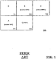
FIG. 1 , the adjacent blocks on the left, top, and top-right of acurrent block 102 are used to predict the motion vector of the current block:
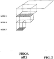
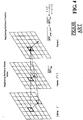
where the pred_mv is defined as the median predictor, and mv_A, mv_B, mv_C are motion vectors forblocks A 104,B 106,C 108, respectively. To better utilize the motion relationship between the seven inter-prediction modes, one proposal applies a hierarchically search order frommode 1 to 7 rather than the proposed search order in the JVT standard. The motion vector of an upper-layer of the current block that is regarded as a candidate to predict the motion vector of the current block is shown inFIG. 2 . Other proposals use more motion vector candidates in the temporal sequences by considering the motion vectors of the corresponding neighboring blocks and all the reference frames. As illustrated inFIG. 3 andFIG. 4 , the corresponding motion vectors of the previous and other reference frames are used as the prediction candidates as well. It should be noted that in the multiple reference frame model inFIG. 4 , a motion vector in a reference frame is scaled according to its temporal distance from the current frame. - The precision of the motion vector prediction plays a critical role in controlling computational reduction steps such as early termination, fast search method, and fast mode decision (e. g., skip mode) in motion estimation.
-
US6483928 discloses motion vector prediction by identifying the best predictor macroblock or predictor vector among pre-established prediction candidate macroblocks chosen among those that are spatially distributed around or near the macroblock under estimation on the same frame and that precede it in the order of scanning. The set of predictors surrounding the macroblock being estimated that have been considered is highlighted inFIG. 5 disclosed therein. - The embodiments described herein provide four approaches for motion vector prediction and schemes to incorporate these approaches to achieve an improved performance in a rate-distortion sense. The methods and apparatus described herein improve the accuracy of motion vector prediction. In one embodiment, the motion vectors of all non-causal blocks of the current block are incorporated in calculating the motion vector predictor by utilizing a more spatial correlation information from the lower resolution version of the original video frame. In another embodiment, chrominance components are integrated with the luminance component to predict more accurate motion vector by using the color information. In yet another embodiment, the system takes into account motion vector information that may be present in a MPEG-2 metadata stream in a video stream transmission system. In still yet another embodiment, a motion vector processing technique is applied to eliminate (i.e., smooth) false motion vectors to improve the accuracy of the technique.
- Other objects, features and advantages will become apparent to those skilled in the art from the following detailed description. It is to be understood, however, that the detailed description and specific examples, while indicating preferred embodiments, are given by way of illustration and not limitation. Many changes and modifications within the scope of the embodiments may be made, and should include all such modifications.
- The invention may be more readily understood by referring to the accompanying drawings in which:
-
FIG. 1 illustrates a prior art motion vector prediction scheme using certain adjacent blocks; -
FIG. 2 illustrates a motion vector prediction scheme using a hierarchical search scheme; -
FIG. 3 illustrates a motion vector prediction scheme using a motion vector from a previous reference frame; -
FIG. 4 illustrates a motion vector prediction scheme using a motion vector from a previous reference frame; -
FIG. 5 illustrates non-causal reference block locations for prediction of motion vectors; -
FIG. 6 is a flow diagram illustrating the use of non-causal reference blocks for prediction of motion vectors; -
FIG. 7 is a diagram illustrating the creation of coarser motion vectors from a downsampled video frame; -
FIG. 8 illustrates a dataflow in a video transmission system; -
FIG. 9 illustrates the use of metadata to predict a motion vector of a corresponding block in a next frame; -
FIG. 10 illustrates the Luma and Chroma components in a color image; -
FIG. 11 illustrates three typical motion vector field arrangements after motion vector prediction; and, -
FIG. 12 is a block diagram of an access terminal and an access point of a wireless system. - Like numerals refer to like elements in the figures.
- The precision of the motion vector prediction plays a key role in controlling the following computation reduction steps like early termination, fast search method, and fast mode decision (e. g. skip mode). The method proposes four new methods to improve the creation of motion svector in video codec. In one embodiment, utilizing the spatial correlation between macroblocks, a video frame is first downsampled to create a lower resolution version video frame and motion estimation is performed on this lower resolution video frame. Hence a set of motion vectors, referred to as "coarser" motion vectors, are obtained. The coarser motion vectors are mapped to the original video frame. Thus, the motion vectors of all neighboring blocks, including the coarser motion vector (derived from the lower resolution video frames) and the causal motion vectors can be utilized as motion vector candidates. In another embodiment, the metadata information fed to the video codec from the upstream MPEG-2 encoder, which contains the MPEG-2 motion vector information for each macroblock that can be used in predicting the motion vector of the corresponding block, is used. In yet another embodiment, the luminance components are incorporated into calculating the motion vector to fully exploiting the color information. In still yet another embodiment, a motion vector smoothing technique is applied to attempt to correct wrongly predicted motion vectors and remove noise.
-
FIG. 5 illustrates the use of non-causal motion vectors to predict the motion vector of acurrent block 502 of acurrent frame 500 in aprediction process 600 as shown in the flow diagram ofFIG. 6 . In contrast to the JVT standard, as noted previously, where only 3 causal blocks are used in the prediction, in one embodiment all of the blocks 504-518 neighboring tocurrent block 502 may be used as candidates for motion vector prediction for all frames in a frame sequence other than where the frame is an intra frame (I frame), as shown instep 602 andstep 604. No prediction is performed for I frames because no motion vector prediction is needed for these types of frames. However, for all other frames, motion vectors for all neighboring blocks are made available through the creation of "coarser" motion vectors, as described in the steps below. Thus, when the video frame is not an I frame, the video frame is downsampled to create alower resolution frame 702, where it is determined if causal motion vectors are available. Referring toFIG. 5 as an example, casual motion vectors are only available for block 504 (A), block 506 (B), and block 508 (C) and block 510 (H) because block 512 (D), block 518 (E), block 516 (F) and block 514 (G) have not yet been processed pursuant to the scanning order. Thus, operation will continue withstep 608, wherevideo frame 500 is downsampled to createlower resolution frame 702, as shown inFIG. 7 . Then, motion estimation is performed on lowerresolution video frame 702, instep 608, to derive a set of motion vectors, referred to as a set of "coarser" motion vectors, which is then mapped back to the original video frame instep 610 and illustrated inFIG. 7 . - Thus, motion vector prediction may be performed in
step 612, even when causal motion vectors are not available as the coarser motion vectors may be used. For example, referring toFIG. 6 , in one embodiment the prediction forcurrent block 502 is performed using the pattern in the current standard for the causal motion vectors, where only block 510 (H), block 506 (B), and block 508 (C) are used for the prediction, but additional vectors as derived from the non-causal blocks (i.e., the coarser motion vectors from) are also used. Specifically, the values set for the three motion vectors for block 510 (H), block 506 (B), and block 508 (C) are determined as follows: - 1. If H is not available (lies outside of the picture), its MV is set to (0, 0).
- 2. If C is not available, its MV is set to A.
- 3. If both B and C are not available, both MVs are set to (O, 0).
- These motion vectors are combined with the coarser motion vectors from block 512 (D), block 518 (E), block 516 (F) and block 514 (G) for the median predictor.
- In another embodiment, the reference blocks used will include all blocks (i.e., block 504 (A), block 506 (B), block 508 (C), block 512 (D), block 518 (E), block 516 (F) and block 514 (G), and block 510 (H)). Then, the median predictor is calculated as:

where mv_PrevCurrent is defined as the motion vector of the corresponding block in the previous reference frame. -
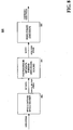
FIG. 8 illustrates a dataflow of avideo transmission system 800, where the video data source fed into avideo codec 806 is transmitted from a decoded MPEG-2 video stream from a MPEG-2decoder 802. In one embodiment, all original source video data is transmitted as a MPEG-2 stream and then decoded. The decoded raw video data is further processed and down-scaled to a quarter VGA (QVGA) size by apreprocessor 804 and presented tovideo codec 806 for encoding into a new format, such as H.264.Video codec 806 also receives such MPEG-2 metadata as frame size, frame rate, macroblock type and a motion vector of each macroblock. The MPEG-2 motion vectors are thus used byvideo codec 806 in one embodiment as a motion vector prediction candidate of the corresponding macroblock during the encoding process. In one embodiment, where the size of the macroblock is a block size of 16x16, the MPEG-2 motion vector is also regarded as the up-layer motion vector for all sub-layer blocks. - In one embodiment, the concept of using the metadata from a previous format to a new format applies only to transcoding scenarios where coding parameters and side information from input format decoding is utilizable in a target encoder such as
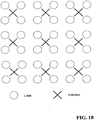
video codec 806. Further, as the motion vector is predicted from the previous frame for both P and B frames, it is only appropriate to predict the motion vector from the metadata for an immediately sequential future frame. As shown inFIG. 9 , the motion vector in sequence at time t-1 is only used to predict the motion vector of the corresponding block sequence at time t. In one embodiment, the reference frame number of the current frame is used to locate the motion vector associated with the metadata of the previous reference frame. - In current video codec standards such as MPEG-4 and H.264, the motion vector of both chrominance components (Cb and Cr) are derived from corresponding luminance component (Y). The chrominance components are then omitted in rate-distortion (RD) and motion vector prediction processes due to the assumption that the luminance component can provide sufficient information and no additional overhead is required to predict the chrominance. However, for video sequences that have low luminance or detailed color information, the chrominance components are useful for more accurate motion vector prediction. Thus, in one embodiment, the motion estimation uses the luminance component and both chrominance components. For example, when the chroma information is taken out in a video frame that has objects with rich color information, the motion of the objects will be harder to predict. Thus, a predicted video frame using color motion prediction will most likely have fewer artifacts than one predicted with only luma component motion prediction.
- As shown in
FIG. 10 , the chrominance components are half-sampled to the horizontal and vertical coordinate compared to the luminance component. If only frame coding is considered, the motion vector of the chrominance component is calculated as follow:

- where (MVL_X, MVL_Y) is the luma motion vector and (MVC_X, MVC_Y) is the chroma motion vector. In one embodiment, the chroma motion vector is used to compute the sum of absolute differences (SAD) for the chroma motion vector that is incorporated into the motion vector prediction and RD optimization. The RD optimization equation for the luma-only is:

- The motion prediction therefore can be viewed as minimizing this Lagrangian cost function. Here the distortion D represents the prediction error measured as SAD of the luminance component, R is the number of bits, the Langrangian multiplier is associated with the quantization parameter (QP) and its value controls the RD trade-off. Considering the chrominance components, the following cost function is introduced:

in which DL and DC represent the distortion in the luma and chroma component respectively, W1 and W2 are experimental weighted parameters that are adaptive to specific video sequences. In one embodiment, because the chroma component has less information, its SAD calculation only uses the integer valued motion vector and therefore no interpolation is necessary. - Any noise or lost frames that is encountered during the video capture and transmission of an encoded video sequence usually translates to a reduction in quality of the sequence during playback. In addition, the block matching motion vector prediction process also introduces errors in motion vector prediction. Vector median filtering (VMF) may be applied as another effective approach to improve motion vector prediction accuracy and reduce noise, while preserving video sequence details. The basic idea behind VMF is that neighboring motion vectors in natural video sequences are always correlated with each other. As illustrated in
FIG. 11 , three types of motion vector fields may appear after the motion vector prediction process, including a smooth regionmotion vector field 1110, anoutlier motion vector 1122 in amotion vector field 1120, and amotion vector field 1130 showing an object edge defined by a plurality of motion vectors 1132(a)-(c) that have a direction opposite the direction of the other motion vectors inmotion vector field 1130. - In one embodiment, a block size of 3x3 is selected to perform the median operation. Continuing to refer to
FIG. 11 , a "wrong" (or outlier) motion vector can be corrected in the outliermotion vector field 1120. However, VMF cannot be used when an object boundary occurs inside the block, such as inmotion vector field 1130. In one embodiment, edge detection and object segmentation methods may be used to address this situation. - Each of the proposed motion vector prediction methods can be used independently or in combined. For example, in one embodiment, during transcoding the motion vector data available in the input video bitstream is extracted and saved for use in a target encoder, such as
video codec 806. This data pertains to the incoming video frames. Motion vector data is remapped to the source frames input to the target encoder. In the process where a single reference frame is used, the motion vector data over previous N frames can be modeled to find the motion trajectory over these N frames. Motion vector smoothing can then be applied to remove outliers and improve the accuracy of the trajectory. Extrapolating the trajectory results in a more accurate estimate of the motion vector for the block to be encoded. In addition, the motion vector data extracted from the input video bitstream may or may not be the true motion vectors. The accuracy of these motion vectors typically depends on the motion search algorithm used in the upstream source encoder. Deriving the motion field of each decoded frame based on these motion vectors and applying a suitable motion vector smoothing technique will help eliminate outliers. When the accuracy of a motion vector cannot be ascertained, other methods, such as those based on motion vectors of spatial neighbors or collocated neighbors, can be adapted. - If sufficient information is available to enable more than one of the proposed methods, the following prioritizations in deriving the motion vector estimation are proposed:
- 1. Rank the accuracy of each method (e.g., using a range from 0-1) based on the additional information available from metadata or pre-processing functions. For example, if de-interlacing or inverse telecine was used as part of pre-processing, the motion vector data needs to be mapped appropriately. If the result of motion vector smoothing is ambiguous, the accuracy of this method is poor. If extracted motion vector, motion vector smoothed motion vector and pre-processed and remapped motion vector are close, the accuracy of this estimate of motion vector is high. Further, for chroma motion estimation, the accuracy depends on the proportion of chroma information relative to the luma information in the source content. When possible, non-causal and causal motion vectors from all reference frames are to be used.
- 2. Apply weights to each method based on its rank.
- 3. Apply a non-linear selection algorithm to select the method.
- The above-described additions to a video codec attempts to improve the accuracy of the motion vector prediction process. Although computation is involved in the implementation of each method, the improvement of the accuracy of the motion vector prediction will reduce computation in the pixel search step, SAD calculation and RD optimization. Thus, the total encoding time will be reduced and better video quality will be achieved.
-
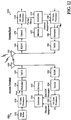
FIG. 12 shows a block diagram of anaccess terminal 1202x and anaccess point 1204x in a wireless system, each of which may implement the motion vector prediction process described herein. An "access terminal," as discussed herein, refers to a device providing voice and/or data connectivity to a user. The access terminal may be connected to a computing device such as a laptop computer or desktop computer, or it may be a self contained device such as a personal digital assistant. The access terminal can also be referred to as a subscriber unit, mobile station, mobile, remote station, remote terminal, user terminal, user agent, or user equipment. The access terminal may be a subscriber station, wireless device, cellular telephone, PCS telephone, a cordless telephone, a Session Initiation Protocol (SIP) phone, a wireless local loop (WLL) station, a personal digital assistant (PDA), a handheld device having wireless connection capability, or other processing device connected to a wireless modem. An "access point," as discussed herein, refers to a device in an access network that communicates over the air-interface, through one or more sectors, with the access terminals. The access point acts as a router between the access terminal and the rest of the access network, which may include an IP network, by converting received air-interface frames to IP packets. The access point also coordinates the management of attributes for the air interface. - For the reverse link, at
access terminal 1202x, a transmit (TX)data processor 1214 receives traffic data from adata buffer 1212, processes (e.g., encodes, interleaves, and symbol maps) each data packet based on a selected coding and modulation scheme, and provides data symbols. A data symbol is a modulation symbol for data, and a pilot symbol is a modulation symbol for pilot (which is known a priori). Amodulator 1216 receives the data symbols, pilot symbols, and possibly signaling for the reverse link, performs (e.g., OFDM) modulation and/or other processing as specified by the system, and provides a stream of output chips. A transmitter unit (TMTR) 1218 processes (e.g., converts to analog, filters, amplifies, and frequency upconverts) the output chip stream and generates a modulated signal, which is transmitted from anantenna 1220. - At
access point 1204x, the modulated signals transmitted byaccess terminal 1202x and other terminals in communication withaccess point 1204x are received by anantenna 1252. A receiver unit (RCVR) 1254 processes (e.g., conditions and digitizes) the received signal fromantenna 1252 and provides received samples. A demodulator (Demod) 1256 processes (e.g., demodulates and detects) the received samples and provides detected data symbols, which are noisy estimate of the data symbols transmitted by the terminals to accesspoint 1204x. A receive (RX)data processor 1258 processes (e.g., symbol demaps, deinterleaves, and decodes) the detected data symbols for each terminal and provides decoded data for that terminal. - For the forward link, at
access point 1204x, traffic data is processed by aTX data processor 1260 to generate data symbols. Amodulator 1262 receives the data symbols, pilot symbols, and signaling for the forward link, performs (e.g., OFDM) modulation and/or other pertinent processing, and provides an output chip stream, which is further conditioned by atransmitter unit 1264 and transmitted fromantenna 1252. The forward link signaling may include power control commands generated by acontroller 1270 for all terminals transmitting on the reverse link to accesspoint 1204x. Ataccess terminal 1202x, the modulated signal transmitted byaccess point 1204x is received byantenna 1220, conditioned and digitized by areceiver unit 1222, and processed by ademodulator 1224 to obtain detected data symbols. AnRX data processor 1226 processes the detected data symbols and provides decoded data for the terminal and the forward link signaling.Controller 1230 receives the power control commands, and controls data transmission and transmit power on the reverse link to accesspoint 1204x.Controllers access terminal 1202x andaccess point 1204x, respectively.Memory units controllers - The disclosed embodiments may be applied to any one or combinations of the following technologies: Code Division Multiple Access (CDMA) systems, Multiple-Carrier CDMA (MC-CDMA), Wideband CDMA (W-CDMA), High-Speed Downlink Packet Access (HSDPA), Time Division Multiple Access (TDMA) systems, Frequency Division Multiple Access (FDMA) systems, and Orthogonal Frequency Division Multiple Access (OFDMA) systems.
- The steps of a method or algorithm described in connection with the embodiments disclosed herein may be embodied directly in hardware, in a software module executed by a processor, or in a combination of the two. A software module may reside in RAM memory, flash memory, ROM memory, EPROM memory, EEPROM memory, registers, a hard disk, a removable disk, a CD-ROM, or any other form of storage medium known in the art. An exemplary storage medium is coupled to the processor, such that the processor can read information from, and write information to, the storage medium. In the alternative, the storage medium may be integral to the processor. The processor and the storage medium may reside in an ASIC. The ASIC may reside in a user terminal. In the alternative, the processor and the storage medium may reside as discrete components in a user terminal.
- It should be noted that the methods described herein may be implemented on a variety of communication hardware, processors and systems known by one of ordinary skill in the art. For example, the general requirement for the client to operate as described herein is that the client has a display to display content and information, a processor to control the operation of the client and a memory for storing data and programs related to the operation of the client. In one embodiment, the client is a cellular phone. In another embodiment, the client is a handheld computer having communications capabilities. In yet another embodiment, the client is a personal computer having communications capabilities. In addition, hardware such as a GPS receiver may be incorporated as necessary in the client to implement the various embodiments described herein. The various illustrative logics, logical blocks, modules, and circuits described in connection with the embodiments disclosed herein may be implemented or performed with a general purpose processor, a digital signal processor (DSP), an application specific integrated circuit (ASIC), a field programmable gate array (FPGA) or other programmable logic device, discrete gate or transistor logic, discrete hardware components, or any combination thereof designed to perform the functions described herein. A general-purpose processor may be a microprocessor, but, in the alternative, the processor may be any conventional processor, controller, microcontroller, or state machine. A processor may also be implemented as a combination of computing devices, e.g., a combination of a DSP and a microprocessor, a plurality of microprocessors, one or more microprocessors in conjunction with a DSP core, or any other such configuration.
- The various illustrative logics, logical blocks, modules, and circuits described in connection with the embodiments disclosed herein may be implemented or performed with a general purpose processor, a digital signal processor (DSP), an application specific integrated circuit (ASIC), a field programmable gate array (FPGA) or other programmable logic device, discrete gate or transistor logic, discrete hardware components, or any combination thereof designed to perform the functions described herein. A general-purpose processor may be a microprocessor, but, in the alternative, the processor may be any conventional processor, controller, microcontroller, or state machine. A processor may also be implemented as a combination of computing devices, e.g., a combination of a DSP and a microprocessor, a plurality of microprocessors, one or more microprocessors in conjunction with a DSP core, or any other such configuration.
- The embodiments described above are exemplary embodiments. Those skilled in the art may now make numerous uses of, and departures from, the above-described embodiments without departing from the inventive concepts disclosed herein. Various modifications to these embodiments may be readily apparent to those skilled in the art, and the generic principles defined herein may be applied to other embodiments, e.g., in an instant messaging service or any general wireless data communication applications, without departing from the scope of the novel aspects described herein. Thus, the scope of the invention is not intended to be limited to the embodiments shown herein but is to be accorded the widest scope consistent with the principles and novel features disclosed herein. The word "exemplary" is used exclusively herein to mean "serving as an example, instance, or illustration." Any embodiment described herein as "exemplary" is not necessarily to be construed as preferred or advantageous over other embodiments. Accordingly, the invention is to be defined solely by the scope of the following claims.
Claims (7)
- A method (600) for motion vector prediction for one area in a video frame, the video frame including a plurality of areas, the method comprising:generating (608) a candidate motion vector for another area of the plurality of areas in the video frame, the another area being adjacent to the one area of the video frame and lacking an associated motion vector; and,using (612) the candidate motion vector to predict a current motion vector for the one area of the video frame,characterised in thatgenerating the candidate motion vector for another area of the plurality of areas in the video frame comprises:performing motion vector processing using at least one motion vector processing technique selected from the group consisting of motion estimation, chrominance and luminance detection, motion vector smoothing, and motion vector prediction using transcoding motion vector data available in an input video bitstream using a target encoder;performing a ranking of each of the used motion vector processing technique;applying weights to each of the used motion vector processing techniques based on its rank; and,applying a non-linear selection algorithm to select one of the used motion vector processing techniques for creating the candidate motion vector,wherein the chrominance and luminance detection motion vector processing technique comprises:deriving a chroma motion vector;computing a sum of absolute differences, SAD, for the chroma motion vector; and,incorporating the SAD value for the chroma motion vector in a motion vector prediction process.
- The method of claim 1, wherein the motion estimation motion vector processing technique comprises:downsampling the video frame and creating a lower resolution video frame;creating a set of motion vectors from the lower resolution video frame; and,mapping each motion vector from the set of motion vectors to at least one area in the plurality of areas in the video frame.
- The method of claim 2, wherein the lower resolution video frame includes a set of blocks and creating the set of motion vectors from the lower resolution video frame comprises performing motion estimation of the set of blocks of the lower resolution video frame to create a set of coarser motion vectors.
- An apparatus (1202,1204) for predicting a motion vector for a current block in a video frame, the current block having a set of neighboring blocks that includes blocks that do not have an associated motion vector, the apparatus comprising:means for deriving (608) a candidate motion vector for each block in the set of neighboring blocks that does not have an associated motion vector; and,means for using (612) the candidate motion vector for each block in the set of neighboring blocks that does not have the associated motion vector to predict a current motion vector for the current block,characterised in thatthe means for generating the candidate motion vector for another area of the plurality of areas in the video frame comprises:means for performing motion vector processing using at least one motion vector processing technique selected from the group consisting of motion estimation, chrominance and luminance detection, motion vector smoothing, and motion vector prediction using transcoding motion vector data available in an input video bitstream using a target encoder;means for performing a ranking of each of the used motion vector processing technique;means for apply weights to each of the used motion vector processing techniques based on its rank; and,means for apply a non-linear selection algorithm to select one of the used motion vector processing techniques for creating the candidate motion vector,wherein the means for chrominance and luminance detection motion vector processing technique comprises:means for deriving a chroma motion vector;means for computing a sum of absolute differences, SAD, for the chroma motion vector; and,means for incorporating the SAD value for the chroma motion vector in a motion vector prediction process.
- The apparatus of claim 4, wherein the current block is contained within a current frame and the means for motion estimation motion vector processing technique comprises:means for downsampling the current frame and creating a lower resolution frame;means for creating a set of motion vectors from the lower resolution frame; and,means for mapping each motion vector from the set of motion vectors to at least one area in the plurality of areas in the video frame.
- The apparatus of claim 5, wherein the lower resolution video frame includes a set of blocks and the means for creating the set of motion vectors from the lower resolution video frame comprises means for performing motion estimation of the set of blocks of the lower resolution video frame to create a set of coarser motion vectors.
- A computer-readable medium comprising code for causing a computer to perform a method of any of the claims 1-3.
Applications Claiming Priority (2)
| Application Number | Priority Date | Filing Date | Title |
|---|---|---|---|
| US58981804P | 2004-07-20 | 2004-07-20 | |
| PCT/US2005/025812 WO2006012383A2 (en) | 2004-07-20 | 2005-07-20 | Method and apparatus for motion vector prediction in temporal video compression |
Publications (2)
| Publication Number | Publication Date |
|---|---|
| EP1784985A2 EP1784985A2 (en) | 2007-05-16 |
| EP1784985B1 true EP1784985B1 (en) | 2017-05-10 |
Family
ID=35045051
Family Applications (1)
| Application Number | Title | Priority Date | Filing Date |
|---|---|---|---|
| EP05775463.2A Not-in-force EP1784985B1 (en) | 2004-07-20 | 2005-07-20 | Method and apparatus for motion vector prediction in temporal video compression |
Country Status (9)
| Country | Link |
|---|---|
| US (1) | US7978770B2 (en) |
| EP (1) | EP1784985B1 (en) |
| JP (1) | JP4699460B2 (en) |
| KR (1) | KR100907847B1 (en) |
| CN (2) | CN102695054B (en) |
| AR (1) | AR049593A1 (en) |
| CA (1) | CA2574590C (en) |
| TW (1) | TWI401957B (en) |
| WO (1) | WO2006012383A2 (en) |
Families Citing this family (94)
| Publication number | Priority date | Publication date | Assignee | Title |
|---|---|---|---|---|
| US7924921B2 (en) * | 2003-09-07 | 2011-04-12 | Microsoft Corporation | Signaling coding and display options in entry point headers |
| US8213779B2 (en) * | 2003-09-07 | 2012-07-03 | Microsoft Corporation | Trick mode elementary stream and receiver system |
| TWI254571B (en) * | 2004-12-07 | 2006-05-01 | Sunplus Technology Co Ltd | Method for fast multiple reference frame motion estimation |
| TWI308841B (en) * | 2005-01-24 | 2009-04-11 | Via Tech Inc | Method and system for reducing the bandwidth access in video encoding |
| US8503525B2 (en) * | 2005-11-04 | 2013-08-06 | National University Of Singapore | Method and a system for determining predicted numbers of processor cycles required for respective segments of a media file for playback of the media file |
| CN1794821A (en) * | 2006-01-11 | 2006-06-28 | 浙江大学 | Method and device of interpolation in grading video compression |
| KR101406156B1 (en) * | 2006-02-02 | 2014-06-13 | 톰슨 라이센싱 | Method and apparatus for adaptive weight selection for motion compensated prediction |
| US8213509B2 (en) * | 2006-10-06 | 2012-07-03 | Calos Fund Limited Liability Company | Video coding on parallel processing systems |
| US8451897B2 (en) * | 2006-12-04 | 2013-05-28 | Atmel Corporation | Highly parallel pipelined hardware architecture for integer and sub-pixel motion estimation |
| KR101383540B1 (en) | 2007-01-03 | 2014-04-09 | 삼성전자주식회사 | Method of estimating motion vector using multiple motion vector predictors, apparatus, encoder, decoder and decoding method |
| US8144778B2 (en) * | 2007-02-22 | 2012-03-27 | Sigma Designs, Inc. | Motion compensated frame rate conversion system and method |
| WO2008153262A1 (en) | 2007-06-15 | 2008-12-18 | Sungkyunkwan University Foundation For Corporate Collaboration | Bi-prediction coding method and apparatus, bi-prediction decoding method and apparatus, and recording midium |
| KR100955396B1 (en) * | 2007-06-15 | 2010-04-29 | 성균관대학교산학협력단 | Bi-prediction coding method and apparatus, bi-prediction decoding method and apparatus, and recording midium |
| US20100271554A1 (en) * | 2007-09-10 | 2010-10-28 | Volker Blume | Method And Apparatus For Motion Estimation In Video Image Data |
| JP2009089332A (en) * | 2007-10-03 | 2009-04-23 | Sony Corp | Motion prediction method and motion predictor |
| US8228992B2 (en) * | 2007-10-12 | 2012-07-24 | Broadcom Corporation | Method and system for power-aware motion estimation for video processing |
| EP2210421A4 (en) | 2007-10-16 | 2013-12-04 | Lg Electronics Inc | A method and an apparatus for processing a video signal |
| FR2925815B1 (en) * | 2007-12-19 | 2010-02-12 | Ateme Sa | METHOD AND DEVICE FOR ESTIMATING SYMMETRIC HIERARCHICAL MOVEMENT OF OBJECTS OF SUCCESSIVE VIDEO IMAGES IN A VIDEO ENCODER |
| KR100939917B1 (en) | 2008-03-07 | 2010-02-03 | 에스케이 텔레콤주식회사 | Encoding system using motion estimation and encoding method using motion estimation |
| US8379152B2 (en) * | 2008-03-31 | 2013-02-19 | Sharp Laboratories Of America, Inc. | Systems and methods for increasing the temporal resolution of video data |
| TW201028964A (en) * | 2009-01-23 | 2010-08-01 | Ind Tech Res Inst | Depth calculating method for two dimension video and apparatus thereof |
| US20100309975A1 (en) * | 2009-06-05 | 2010-12-09 | Apple Inc. | Image acquisition and transcoding system |
| US9654792B2 (en) | 2009-07-03 | 2017-05-16 | Intel Corporation | Methods and systems for motion vector derivation at a video decoder |
| US8917769B2 (en) | 2009-07-03 | 2014-12-23 | Intel Corporation | Methods and systems to estimate motion based on reconstructed reference frames at a video decoder |
| US8462852B2 (en) | 2009-10-20 | 2013-06-11 | Intel Corporation | Methods and apparatus for adaptively choosing a search range for motion estimation |
| US20110026596A1 (en) * | 2009-07-28 | 2011-02-03 | Wei Hong | Method and System for Block-Based Motion Estimation for Motion-Compensated Frame Rate Conversion |
| KR101452859B1 (en) | 2009-08-13 | 2014-10-23 | 삼성전자주식회사 | Method and apparatus for encoding and decoding motion vector |
| KR101356613B1 (en) | 2009-08-21 | 2014-02-06 | 에스케이텔레콤 주식회사 | Video Coding Method and Apparatus by Using Adaptive Motion Vector Resolution |
| WO2011021914A2 (en) | 2009-08-21 | 2011-02-24 | 에스케이텔레콤 주식회사 | Method and apparatus for encoding/decoding images using adaptive motion vector resolution |
| TWI566586B (en) * | 2009-10-20 | 2017-01-11 | 湯姆生特許公司 | Method for coding a block of a sequence of images and method for reconstructing said block |
| TWI419519B (en) * | 2009-12-22 | 2013-12-11 | Ind Tech Res Inst | System and method for transmitting network packets adapted for multimedia streams |
| KR101522850B1 (en) * | 2010-01-14 | 2015-05-26 | 삼성전자주식회사 | Method and apparatus for encoding/decoding motion vector |
| US9036692B2 (en) * | 2010-01-18 | 2015-05-19 | Mediatek Inc. | Motion prediction method |
| US8594199B2 (en) * | 2010-03-08 | 2013-11-26 | Qualcomm Incorporated | Apparatus and method for motion vector filtering based on local image segmentation and lattice maps |
| JP5913283B2 (en) * | 2010-04-22 | 2016-04-27 | 聯發科技股▲ふん▼有限公司Mediatek Inc. | Motion prediction method |
| KR101106634B1 (en) | 2010-05-12 | 2012-01-20 | 전남대학교산학협력단 | Apparatus and Method for Motion Vector Smoothing |
| US9300970B2 (en) * | 2010-07-09 | 2016-03-29 | Samsung Electronics Co., Ltd. | Methods and apparatuses for encoding and decoding motion vector |
| WO2012011432A1 (en) * | 2010-07-20 | 2012-01-26 | 株式会社エヌ・ティ・ティ・ドコモ | Image prediction encoding device, image prediction encoding method, image prediction encoding program, image prediction decoding device, image prediction decoding method, and image prediction decoding program |
| CN102377992B (en) * | 2010-08-06 | 2014-06-04 | 华为技术有限公司 | Method and device for obtaining predicted value of motion vector |
| EP3907999B1 (en) * | 2010-09-02 | 2023-11-22 | LG Electronics, Inc. | Inter prediction |
| US20120294370A1 (en) * | 2010-10-06 | 2012-11-22 | Yi-Jen Chiu | System and method for low complexity motion vector derivation |
| CN106937122B (en) * | 2010-10-28 | 2020-03-27 | 韩国电子通信研究院 | Video decoding method |
| US8611415B1 (en) * | 2010-11-15 | 2013-12-17 | Google Inc. | System and method for coding using improved motion estimation |
| US9509995B2 (en) | 2010-12-21 | 2016-11-29 | Intel Corporation | System and method for enhanced DMVD processing |
| US8891626B1 (en) | 2011-04-05 | 2014-11-18 | Google Inc. | Center of motion for encoding motion fields |
| WO2012167711A1 (en) | 2011-06-10 | 2012-12-13 | Mediatek Inc. | Method and apparatus of scalable video coding |
| WO2013006386A1 (en) | 2011-07-01 | 2013-01-10 | General Instrument Corporation | Motion vector prediction design simplification |
| US9586141B2 (en) | 2011-09-08 | 2017-03-07 | Paofit Holdings Pte. Ltd. | System and method for visualizing synthetic objects within real-world video clip |
| US20140241434A1 (en) * | 2011-10-11 | 2014-08-28 | Mediatek Inc | Method and apparatus of motion and disparity vector derivation for 3d video coding and hevc |
| BR112014010539A2 (en) | 2011-11-04 | 2017-04-18 | Motorola Mobility Llc | motion vector scaling for non-uniform motion vector network |
| KR20130050405A (en) * | 2011-11-07 | 2013-05-16 | 오수미 | Method for determining temporal candidate in inter prediction mode |
| TWI523497B (en) * | 2011-11-10 | 2016-02-21 | Sony Corp | Image processing apparatus and method |
| EP3965425A3 (en) | 2011-12-23 | 2022-06-08 | Electronics And Telecommunications Research Institute | Method and apparatus for setting reference picture index of temporal merging candidate |
| US8908767B1 (en) | 2012-02-09 | 2014-12-09 | Google Inc. | Temporal motion vector prediction |
| US9460495B2 (en) * | 2012-04-06 | 2016-10-04 | Microsoft Technology Licensing, Llc | Joint video stabilization and rolling shutter correction on a generic platform |
| US9420285B2 (en) | 2012-04-12 | 2016-08-16 | Qualcomm Incorporated | Inter-layer mode derivation for prediction in scalable video coding |
| US9491458B2 (en) | 2012-04-12 | 2016-11-08 | Qualcomm Incorporated | Scalable video coding prediction with non-causal information |
| US9172970B1 (en) | 2012-05-29 | 2015-10-27 | Google Inc. | Inter frame candidate selection for a video encoder |
| US11317101B2 (en) | 2012-06-12 | 2022-04-26 | Google Inc. | Inter frame candidate selection for a video encoder |
| US9288484B1 (en) | 2012-08-30 | 2016-03-15 | Google Inc. | Sparse coding dictionary priming |
| US9503746B2 (en) | 2012-10-08 | 2016-11-22 | Google Inc. | Determine reference motion vectors |
| US9485515B2 (en) | 2013-08-23 | 2016-11-01 | Google Inc. | Video coding using reference motion vectors |
| WO2014083491A2 (en) * | 2012-11-27 | 2014-06-05 | Squid Design Systems Pvt Ltd | System and method of mapping multiple reference frame motion estimation on multi-core dsp architecture |
| WO2014146079A1 (en) | 2013-03-15 | 2014-09-18 | Zenkich Raymond | System and method for non-uniform video coding |
| US9300906B2 (en) | 2013-03-29 | 2016-03-29 | Google Inc. | Pull frame interpolation |
| US9313493B1 (en) | 2013-06-27 | 2016-04-12 | Google Inc. | Advanced motion estimation |
| RU2654129C2 (en) | 2013-10-14 | 2018-05-16 | МАЙКРОСОФТ ТЕКНОЛОДЖИ ЛАЙСЕНСИНГ, ЭлЭлСи | Features of intra block copy prediction mode for video and image coding and decoding |
| CN105659602B (en) | 2013-10-14 | 2019-10-08 | 微软技术许可有限责任公司 | Coder side option for the intra block duplication prediction mode that video and image encode |
| CA2925183C (en) | 2013-10-14 | 2020-03-10 | Microsoft Technology Licensing, Llc | Features of base color index map mode for video and image coding and decoding |
| US10390034B2 (en) | 2014-01-03 | 2019-08-20 | Microsoft Technology Licensing, Llc | Innovations in block vector prediction and estimation of reconstructed sample values within an overlap area |
| CN103747264B (en) * | 2014-01-03 | 2017-10-17 | 华为技术有限公司 | Method, encoding device and the decoding device of predicted motion vector |
| BR112016015080A2 (en) | 2014-01-03 | 2017-08-08 | Microsoft Technology Licensing Llc | BLOCK VECTOR PREDICTION IN VIDEO AND IMAGE ENCODING / DECODING |
| US11284103B2 (en) | 2014-01-17 | 2022-03-22 | Microsoft Technology Licensing, Llc | Intra block copy prediction with asymmetric partitions and encoder-side search patterns, search ranges and approaches to partitioning |
| US10542274B2 (en) | 2014-02-21 | 2020-01-21 | Microsoft Technology Licensing, Llc | Dictionary encoding and decoding of screen content |
| CA2939431C (en) | 2014-03-04 | 2020-09-22 | Microsoft Techology Licensing, Llc | Block flipping and skip mode in intra block copy prediction |
| EP3149945A1 (en) | 2014-05-30 | 2017-04-05 | Paofit Holdings Pte Ltd | Systems and methods for motion-vector-aided video interpolation using real-time smooth video playback speed variation |
| KR102413529B1 (en) | 2014-06-19 | 2022-06-24 | 마이크로소프트 테크놀로지 라이센싱, 엘엘씨 | Unified intra block copy and inter prediction modes |
| US9286653B2 (en) | 2014-08-06 | 2016-03-15 | Google Inc. | System and method for increasing the bit depth of images |
| US9153017B1 (en) | 2014-08-15 | 2015-10-06 | Google Inc. | System and method for optimized chroma subsampling |
| US10554965B2 (en) | 2014-08-18 | 2020-02-04 | Google Llc | Motion-compensated partitioning |
| RU2679201C2 (en) | 2014-09-30 | 2019-02-06 | МАЙКРОСОФТ ТЕКНОЛОДЖИ ЛАЙСЕНСИНГ, ЭлЭлСи | Rules for intra-picture prediction modes when wavefront parallel processing is enabled |
| US9591325B2 (en) * | 2015-01-27 | 2017-03-07 | Microsoft Technology Licensing, Llc | Special case handling for merged chroma blocks in intra block copy prediction mode |
| CN106664405B (en) | 2015-06-09 | 2020-06-09 | 微软技术许可有限责任公司 | Robust encoding/decoding of escape-coded pixels with palette mode |
| US9704298B2 (en) | 2015-06-23 | 2017-07-11 | Paofit Holdings Pte Ltd. | Systems and methods for generating 360 degree mixed reality environments |
| US10397600B1 (en) | 2016-01-29 | 2019-08-27 | Google Llc | Dynamic reference motion vector coding mode |
| US10462457B2 (en) | 2016-01-29 | 2019-10-29 | Google Llc | Dynamic reference motion vector coding mode |
| US10419777B2 (en) | 2016-12-22 | 2019-09-17 | Google Llc | Non-causal overlapped block prediction in variable block size video coding |
| US20180184107A1 (en) * | 2016-12-28 | 2018-06-28 | Novatek Microelectronics Corp. | Motion estimation method and motion estimation apparatus |
| CN109089119B (en) * | 2017-06-13 | 2021-08-13 | 浙江大学 | Method and equipment for predicting motion vector |
| KR102476204B1 (en) * | 2017-10-19 | 2022-12-08 | 삼성전자주식회사 | Multi-codec encoder and multi-codec encoding system including the same |
| US10986349B2 (en) | 2017-12-29 | 2021-04-20 | Microsoft Technology Licensing, Llc | Constraints on locations of reference blocks for intra block copy prediction |
| CN110933426B (en) * | 2018-09-20 | 2022-03-01 | 杭州海康威视数字技术股份有限公司 | Decoding and encoding method and device thereof |
| CN113498609B (en) * | 2018-12-31 | 2023-06-20 | 北京达佳互联信息技术有限公司 | Picture resolution dependent configuration for video codec |
| US20230097592A1 (en) * | 2021-09-30 | 2023-03-30 | Waymo Llc | Systems, Methods, and Apparatus for Aligning Image Frames |
Family Cites Families (10)
| Publication number | Priority date | Publication date | Assignee | Title |
|---|---|---|---|---|
| KR0181069B1 (en) * | 1995-11-08 | 1999-05-01 | 배순훈 | Motion estimation apparatus |
| EP0897247A3 (en) * | 1997-08-14 | 2001-02-07 | Philips Patentverwaltung GmbH | Method for computing motion vectors |
| IT1313382B1 (en) * | 1999-03-18 | 2002-07-23 | St Microelectronics Srl | ESTIMATE OF THE RECURRENT MOTION TEMPORAL SPACE WITH 1/2 MACROBLOCK AND 1/4 PIXEL SUB-SAMPLING |
| US6567469B1 (en) * | 2000-03-23 | 2003-05-20 | Koninklijke Philips Electronics N.V. | Motion estimation algorithm suitable for H.261 videoconferencing applications |
| JP4574090B2 (en) * | 2001-09-21 | 2010-11-04 | 三菱電機株式会社 | Movie data converter and movie data conversion program |
| FR2833797B1 (en) * | 2001-12-19 | 2004-02-13 | Thomson Licensing Sa | METHOD FOR ESTIMATING THE DOMINANT MOVEMENT IN A SEQUENCE OF IMAGES |
| JP4102970B2 (en) * | 2002-01-21 | 2008-06-18 | 日本電気株式会社 | Video code string conversion method |
| US7173971B2 (en) * | 2002-11-20 | 2007-02-06 | Ub Video Inc. | Trailing artifact avoidance system and method |
| CN1181691C (en) * | 2003-01-24 | 2004-12-22 | 杭州国芯科技有限公司 | Vidio motion estimation method |
| US20050286777A1 (en) * | 2004-06-27 | 2005-12-29 | Roger Kumar | Encoding and decoding images |
-
2005
- 2005-07-20 WO PCT/US2005/025812 patent/WO2006012383A2/en active Application Filing
- 2005-07-20 EP EP05775463.2A patent/EP1784985B1/en not_active Not-in-force
- 2005-07-20 TW TW094124540A patent/TWI401957B/en not_active IP Right Cessation
- 2005-07-20 JP JP2007522724A patent/JP4699460B2/en not_active Expired - Fee Related
- 2005-07-20 AR ARP050103010A patent/AR049593A1/en unknown
- 2005-07-20 KR KR1020077003881A patent/KR100907847B1/en not_active IP Right Cessation
- 2005-07-20 CN CN201210148672.8A patent/CN102695054B/en not_active Expired - Fee Related
- 2005-07-20 CN CN2005800315320A patent/CN101023676B/en not_active Expired - Fee Related
- 2005-07-20 US US11/186,126 patent/US7978770B2/en not_active Expired - Fee Related
- 2005-07-20 CA CA2574590A patent/CA2574590C/en not_active Expired - Fee Related
Non-Patent Citations (1)
| Title |
|---|
| None * |
Also Published As
| Publication number | Publication date |
|---|---|
| AR049593A1 (en) | 2006-08-16 |
| CN101023676A (en) | 2007-08-22 |
| CN102695054B (en) | 2015-01-28 |
| JP2008507914A (en) | 2008-03-13 |
| WO2006012383A2 (en) | 2006-02-02 |
| JP4699460B2 (en) | 2011-06-08 |
| CA2574590A1 (en) | 2006-02-02 |
| WO2006012383A3 (en) | 2006-06-15 |
| TW200627966A (en) | 2006-08-01 |
| CN101023676B (en) | 2012-06-27 |
| CA2574590C (en) | 2013-02-19 |
| KR20070040398A (en) | 2007-04-16 |
| CN102695054A (en) | 2012-09-26 |
| KR100907847B1 (en) | 2009-07-14 |
| US20060018381A1 (en) | 2006-01-26 |
| US7978770B2 (en) | 2011-07-12 |
| TWI401957B (en) | 2013-07-11 |
| EP1784985A2 (en) | 2007-05-16 |
Similar Documents
| Publication | Publication Date | Title |
|---|---|---|
| EP1784985B1 (en) | Method and apparatus for motion vector prediction in temporal video compression | |
| US8553776B2 (en) | Method and apparatus for motion vector assignment | |
| US9521411B2 (en) | Method and apparatus for encoder assisted-frame rate up conversion (EA-FRUC) for video compression | |
| US20060017843A1 (en) | Method and apparatus for frame rate up conversion with multiple reference frames and variable block sizes | |
| US7672377B2 (en) | Method and system for video encoding and transcoding | |
| JP5175370B2 (en) | Method and apparatus for using frame rate up-conversion technique in scalable video coding | |
| US6711211B1 (en) | Method for encoding and decoding video information, a motion compensated video encoder and a corresponding decoder | |
| Suzuki et al. | An improved low delay inter frame coding using template matching averaging | |
| Kim et al. | Efficient motion estimation using a modified early termination algorithm in H. 264 |
Legal Events
| Date | Code | Title | Description |
|---|---|---|---|
| PUAI | Public reference made under article 153(3) epc to a published international application that has entered the european phase |
Free format text: ORIGINAL CODE: 0009012 |
|
| 17P | Request for examination filed |
Effective date: 20070212 |
|
| AK | Designated contracting states |
Kind code of ref document: A2 Designated state(s): AT BE BG CH CY CZ DE DK EE ES FI FR GB GR HU IE IS IT LI LT LU LV MC NL PL PT RO SE SI SK TR |
|
| DAX | Request for extension of the european patent (deleted) | ||
| 17Q | First examination report despatched |
Effective date: 20100913 |
|
| RIC1 | Information provided on ipc code assigned before grant |
Ipc: H04N 19/56 20140101AFI20160511BHEP |
|
| REG | Reference to a national code |
Ref country code: DE Ref legal event code: R079 Ref document number: 602005051928 Country of ref document: DE Free format text: PREVIOUS MAIN CLASS: H04N0007260000 Ipc: H04N0005140000 |
|
| GRAJ | Information related to disapproval of communication of intention to grant by the applicant or resumption of examination proceedings by the epo deleted |
Free format text: ORIGINAL CODE: EPIDOSDIGR1 |
|
| RIC1 | Information provided on ipc code assigned before grant |
Ipc: H04N 19/46 20140101ALI20160624BHEP Ipc: H04N 19/53 20140101ALI20160624BHEP Ipc: H04N 19/52 20140101ALI20160624BHEP Ipc: H04N 19/513 20140101ALI20160624BHEP Ipc: H04N 5/14 20060101AFI20160624BHEP Ipc: H04N 19/40 20140101ALI20160624BHEP Ipc: H04N 19/59 20140101ALI20160624BHEP |
|
| GRAP | Despatch of communication of intention to grant a patent |
Free format text: ORIGINAL CODE: EPIDOSNIGR1 |
|
| GRAJ | Information related to disapproval of communication of intention to grant by the applicant or resumption of examination proceedings by the epo deleted |
Free format text: ORIGINAL CODE: EPIDOSDIGR1 |
|
| INTG | Intention to grant announced |
Effective date: 20160811 |
|
| GRAP | Despatch of communication of intention to grant a patent |
Free format text: ORIGINAL CODE: EPIDOSNIGR1 |
|
| INTG | Intention to grant announced |
Effective date: 20160916 |
|
| GRAJ | Information related to disapproval of communication of intention to grant by the applicant or resumption of examination proceedings by the epo deleted |
Free format text: ORIGINAL CODE: EPIDOSDIGR1 |
|
| INTC | Intention to grant announced (deleted) | ||
| GRAR | Information related to intention to grant a patent recorded |
Free format text: ORIGINAL CODE: EPIDOSNIGR71 |
|
| GRAS | Grant fee paid |
Free format text: ORIGINAL CODE: EPIDOSNIGR3 |
|
| GRAA | (expected) grant |
Free format text: ORIGINAL CODE: 0009210 |
|
| INTG | Intention to grant announced |
Effective date: 20170303 |
|
| AK | Designated contracting states |
Kind code of ref document: B1 Designated state(s): AT BE BG CH CY CZ DE DK EE ES FI FR GB GR HU IE IS IT LI LT LU LV MC NL PL PT RO SE SI SK TR |
|
| REG | Reference to a national code |
Ref country code: GB Ref legal event code: FG4D |
|
| REG | Reference to a national code |
Ref country code: AT Ref legal event code: REF Ref document number: 893425 Country of ref document: AT Kind code of ref document: T Effective date: 20170515 Ref country code: CH Ref legal event code: EP |
|
| REG | Reference to a national code |
Ref country code: IE Ref legal event code: FG4D |
|
| REG | Reference to a national code |
Ref country code: DE Ref legal event code: R096 Ref document number: 602005051928 Country of ref document: DE |
|
| REG | Reference to a national code |
Ref country code: FR Ref legal event code: PLFP Year of fee payment: 13 |
|
| REG | Reference to a national code |
Ref country code: NL Ref legal event code: MP Effective date: 20170510 |
|
| REG | Reference to a national code |
Ref country code: LT Ref legal event code: MG4D |
|
| REG | Reference to a national code |
Ref country code: AT Ref legal event code: MK05 Ref document number: 893425 Country of ref document: AT Kind code of ref document: T Effective date: 20170510 |
|
| PG25 | Lapsed in a contracting state [announced via postgrant information from national office to epo] |
Ref country code: GR Free format text: LAPSE BECAUSE OF FAILURE TO SUBMIT A TRANSLATION OF THE DESCRIPTION OR TO PAY THE FEE WITHIN THE PRESCRIBED TIME-LIMIT Effective date: 20170811 Ref country code: ES Free format text: LAPSE BECAUSE OF FAILURE TO SUBMIT A TRANSLATION OF THE DESCRIPTION OR TO PAY THE FEE WITHIN THE PRESCRIBED TIME-LIMIT Effective date: 20170510 Ref country code: LT Free format text: LAPSE BECAUSE OF FAILURE TO SUBMIT A TRANSLATION OF THE DESCRIPTION OR TO PAY THE FEE WITHIN THE PRESCRIBED TIME-LIMIT Effective date: 20170510 Ref country code: AT Free format text: LAPSE BECAUSE OF FAILURE TO SUBMIT A TRANSLATION OF THE DESCRIPTION OR TO PAY THE FEE WITHIN THE PRESCRIBED TIME-LIMIT Effective date: 20170510 Ref country code: FI Free format text: LAPSE BECAUSE OF FAILURE TO SUBMIT A TRANSLATION OF THE DESCRIPTION OR TO PAY THE FEE WITHIN THE PRESCRIBED TIME-LIMIT Effective date: 20170510 |
|
| PGFP | Annual fee paid to national office [announced via postgrant information from national office to epo] |
Ref country code: DE Payment date: 20170606 Year of fee payment: 13 Ref country code: GB Payment date: 20170719 Year of fee payment: 13 Ref country code: FR Payment date: 20170719 Year of fee payment: 13 |
|
| PG25 | Lapsed in a contracting state [announced via postgrant information from national office to epo] |
Ref country code: PL Free format text: LAPSE BECAUSE OF FAILURE TO SUBMIT A TRANSLATION OF THE DESCRIPTION OR TO PAY THE FEE WITHIN THE PRESCRIBED TIME-LIMIT Effective date: 20170510 Ref country code: LV Free format text: LAPSE BECAUSE OF FAILURE TO SUBMIT A TRANSLATION OF THE DESCRIPTION OR TO PAY THE FEE WITHIN THE PRESCRIBED TIME-LIMIT Effective date: 20170510 Ref country code: SE Free format text: LAPSE BECAUSE OF FAILURE TO SUBMIT A TRANSLATION OF THE DESCRIPTION OR TO PAY THE FEE WITHIN THE PRESCRIBED TIME-LIMIT Effective date: 20170510 Ref country code: NL Free format text: LAPSE BECAUSE OF FAILURE TO SUBMIT A TRANSLATION OF THE DESCRIPTION OR TO PAY THE FEE WITHIN THE PRESCRIBED TIME-LIMIT Effective date: 20170510 Ref country code: IS Free format text: LAPSE BECAUSE OF FAILURE TO SUBMIT A TRANSLATION OF THE DESCRIPTION OR TO PAY THE FEE WITHIN THE PRESCRIBED TIME-LIMIT Effective date: 20170910 Ref country code: BG Free format text: LAPSE BECAUSE OF FAILURE TO SUBMIT A TRANSLATION OF THE DESCRIPTION OR TO PAY THE FEE WITHIN THE PRESCRIBED TIME-LIMIT Effective date: 20170810 |
|
| PG25 | Lapsed in a contracting state [announced via postgrant information from national office to epo] |
Ref country code: CZ Free format text: LAPSE BECAUSE OF FAILURE TO SUBMIT A TRANSLATION OF THE DESCRIPTION OR TO PAY THE FEE WITHIN THE PRESCRIBED TIME-LIMIT Effective date: 20170510 Ref country code: SK Free format text: LAPSE BECAUSE OF FAILURE TO SUBMIT A TRANSLATION OF THE DESCRIPTION OR TO PAY THE FEE WITHIN THE PRESCRIBED TIME-LIMIT Effective date: 20170510 Ref country code: DK Free format text: LAPSE BECAUSE OF FAILURE TO SUBMIT A TRANSLATION OF THE DESCRIPTION OR TO PAY THE FEE WITHIN THE PRESCRIBED TIME-LIMIT Effective date: 20170510 Ref country code: EE Free format text: LAPSE BECAUSE OF FAILURE TO SUBMIT A TRANSLATION OF THE DESCRIPTION OR TO PAY THE FEE WITHIN THE PRESCRIBED TIME-LIMIT Effective date: 20170510 Ref country code: RO Free format text: LAPSE BECAUSE OF FAILURE TO SUBMIT A TRANSLATION OF THE DESCRIPTION OR TO PAY THE FEE WITHIN THE PRESCRIBED TIME-LIMIT Effective date: 20170510 |
|
| REG | Reference to a national code |
Ref country code: DE Ref legal event code: R097 Ref document number: 602005051928 Country of ref document: DE |
|
| PG25 | Lapsed in a contracting state [announced via postgrant information from national office to epo] |
Ref country code: IT Free format text: LAPSE BECAUSE OF FAILURE TO SUBMIT A TRANSLATION OF THE DESCRIPTION OR TO PAY THE FEE WITHIN THE PRESCRIBED TIME-LIMIT Effective date: 20170510 |
|
| REG | Reference to a national code |
Ref country code: CH Ref legal event code: PL |
|
| PLBE | No opposition filed within time limit |
Free format text: ORIGINAL CODE: 0009261 |
|
| STAA | Information on the status of an ep patent application or granted ep patent |
Free format text: STATUS: NO OPPOSITION FILED WITHIN TIME LIMIT |
|
| 26N | No opposition filed |
Effective date: 20180213 |
|
| REG | Reference to a national code |
Ref country code: IE Ref legal event code: MM4A |
|
| PG25 | Lapsed in a contracting state [announced via postgrant information from national office to epo] |
Ref country code: IE Free format text: LAPSE BECAUSE OF NON-PAYMENT OF DUE FEES Effective date: 20170720 Ref country code: CH Free format text: LAPSE BECAUSE OF NON-PAYMENT OF DUE FEES Effective date: 20170731 Ref country code: LI Free format text: LAPSE BECAUSE OF NON-PAYMENT OF DUE FEES Effective date: 20170731 |
|
| PG25 | Lapsed in a contracting state [announced via postgrant information from national office to epo] |
Ref country code: SI Free format text: LAPSE BECAUSE OF FAILURE TO SUBMIT A TRANSLATION OF THE DESCRIPTION OR TO PAY THE FEE WITHIN THE PRESCRIBED TIME-LIMIT Effective date: 20170510 |
|
| REG | Reference to a national code |
Ref country code: BE Ref legal event code: MM Effective date: 20170731 |
|
| PG25 | Lapsed in a contracting state [announced via postgrant information from national office to epo] |
Ref country code: LU Free format text: LAPSE BECAUSE OF NON-PAYMENT OF DUE FEES Effective date: 20170720 |
|
| PG25 | Lapsed in a contracting state [announced via postgrant information from national office to epo] |
Ref country code: BE Free format text: LAPSE BECAUSE OF NON-PAYMENT OF DUE FEES Effective date: 20170731 |
|
| REG | Reference to a national code |
Ref country code: DE Ref legal event code: R119 Ref document number: 602005051928 Country of ref document: DE |
|
| GBPC | Gb: european patent ceased through non-payment of renewal fee |
Effective date: 20180720 |
|
| PG25 | Lapsed in a contracting state [announced via postgrant information from national office to epo] |
Ref country code: DE Free format text: LAPSE BECAUSE OF NON-PAYMENT OF DUE FEES Effective date: 20190201 Ref country code: GB Free format text: LAPSE BECAUSE OF NON-PAYMENT OF DUE FEES Effective date: 20180720 Ref country code: FR Free format text: LAPSE BECAUSE OF NON-PAYMENT OF DUE FEES Effective date: 20180731 |
|
| PG25 | Lapsed in a contracting state [announced via postgrant information from national office to epo] |
Ref country code: HU Free format text: LAPSE BECAUSE OF FAILURE TO SUBMIT A TRANSLATION OF THE DESCRIPTION OR TO PAY THE FEE WITHIN THE PRESCRIBED TIME-LIMIT; INVALID AB INITIO Effective date: 20050720 Ref country code: MC Free format text: LAPSE BECAUSE OF FAILURE TO SUBMIT A TRANSLATION OF THE DESCRIPTION OR TO PAY THE FEE WITHIN THE PRESCRIBED TIME-LIMIT Effective date: 20170510 |
|
| PG25 | Lapsed in a contracting state [announced via postgrant information from national office to epo] |
Ref country code: CY Free format text: LAPSE BECAUSE OF NON-PAYMENT OF DUE FEES Effective date: 20170510 |
|
| PG25 | Lapsed in a contracting state [announced via postgrant information from national office to epo] |
Ref country code: TR Free format text: LAPSE BECAUSE OF FAILURE TO SUBMIT A TRANSLATION OF THE DESCRIPTION OR TO PAY THE FEE WITHIN THE PRESCRIBED TIME-LIMIT Effective date: 20170510 |
|
| PG25 | Lapsed in a contracting state [announced via postgrant information from national office to epo] |
Ref country code: PT Free format text: LAPSE BECAUSE OF FAILURE TO SUBMIT A TRANSLATION OF THE DESCRIPTION OR TO PAY THE FEE WITHIN THE PRESCRIBED TIME-LIMIT Effective date: 20170510 |