EP1784290B1 - Rip fence for a table saw - Google Patents
Rip fence for a table saw Download PDFInfo
- Publication number
- EP1784290B1 EP1784290B1 EP20050792561 EP05792561A EP1784290B1 EP 1784290 B1 EP1784290 B1 EP 1784290B1 EP 20050792561 EP20050792561 EP 20050792561 EP 05792561 A EP05792561 A EP 05792561A EP 1784290 B1 EP1784290 B1 EP 1784290B1
- Authority
- EP
- European Patent Office
- Prior art keywords
- fence
- end portions
- positional
- rip fence
- saw
- Prior art date
- Legal status (The legal status is an assumption and is not a legal conclusion. Google has not performed a legal analysis and makes no representation as to the accuracy of the status listed.)
- Expired - Lifetime
Links
Images




Classifications
-
- B—PERFORMING OPERATIONS; TRANSPORTING
- B27—WORKING OR PRESERVING WOOD OR SIMILAR MATERIAL; NAILING OR STAPLING MACHINES IN GENERAL
- B27B—SAWS FOR WOOD OR SIMILAR MATERIAL; COMPONENTS OR ACCESSORIES THEREFOR
- B27B27/00—Guide fences or stops for timber in saw mills or sawing machines; Measuring equipment thereon
- B27B27/02—Guide fences or stops for timber in saw mills or sawing machines; Measuring equipment thereon arranged laterally and parallel with respect to the plane of the saw blade
-
- B—PERFORMING OPERATIONS; TRANSPORTING
- B23—MACHINE TOOLS; METAL-WORKING NOT OTHERWISE PROVIDED FOR
- B23Q—DETAILS, COMPONENTS, OR ACCESSORIES FOR MACHINE TOOLS, e.g. ARRANGEMENTS FOR COPYING OR CONTROLLING; MACHINE TOOLS IN GENERAL CHARACTERISED BY THE CONSTRUCTION OF PARTICULAR DETAILS OR COMPONENTS; COMBINATIONS OR ASSOCIATIONS OF METAL-WORKING MACHINES, NOT DIRECTED TO A PARTICULAR RESULT
- B23Q3/00—Devices holding, supporting, or positioning work or tools, of a kind normally removable from the machine
- B23Q3/005—Guides for workpieces
- B23Q3/007—Guides for workpieces provided with measuring means allowing the positioning of the guides
-
- Y—GENERAL TAGGING OF NEW TECHNOLOGICAL DEVELOPMENTS; GENERAL TAGGING OF CROSS-SECTIONAL TECHNOLOGIES SPANNING OVER SEVERAL SECTIONS OF THE IPC; TECHNICAL SUBJECTS COVERED BY FORMER USPC CROSS-REFERENCE ART COLLECTIONS [XRACs] AND DIGESTS
- Y10—TECHNICAL SUBJECTS COVERED BY FORMER USPC
- Y10T—TECHNICAL SUBJECTS COVERED BY FORMER US CLASSIFICATION
- Y10T83/00—Cutting
- Y10T83/04—Processes
-
- Y—GENERAL TAGGING OF NEW TECHNOLOGICAL DEVELOPMENTS; GENERAL TAGGING OF CROSS-SECTIONAL TECHNOLOGIES SPANNING OVER SEVERAL SECTIONS OF THE IPC; TECHNICAL SUBJECTS COVERED BY FORMER USPC CROSS-REFERENCE ART COLLECTIONS [XRACs] AND DIGESTS
- Y10—TECHNICAL SUBJECTS COVERED BY FORMER USPC
- Y10T—TECHNICAL SUBJECTS COVERED BY FORMER US CLASSIFICATION
- Y10T83/00—Cutting
- Y10T83/727—With means to guide moving work
-
- Y—GENERAL TAGGING OF NEW TECHNOLOGICAL DEVELOPMENTS; GENERAL TAGGING OF CROSS-SECTIONAL TECHNOLOGIES SPANNING OVER SEVERAL SECTIONS OF THE IPC; TECHNICAL SUBJECTS COVERED BY FORMER USPC CROSS-REFERENCE ART COLLECTIONS [XRACs] AND DIGESTS
- Y10—TECHNICAL SUBJECTS COVERED BY FORMER USPC
- Y10T—TECHNICAL SUBJECTS COVERED BY FORMER US CLASSIFICATION
- Y10T83/00—Cutting
- Y10T83/748—With work immobilizer
- Y10T83/7593—Work-stop abutment
- Y10T83/76—With scale or indicator
-
- Y—GENERAL TAGGING OF NEW TECHNOLOGICAL DEVELOPMENTS; GENERAL TAGGING OF CROSS-SECTIONAL TECHNOLOGIES SPANNING OVER SEVERAL SECTIONS OF THE IPC; TECHNICAL SUBJECTS COVERED BY FORMER USPC CROSS-REFERENCE ART COLLECTIONS [XRACs] AND DIGESTS
- Y10—TECHNICAL SUBJECTS COVERED BY FORMER USPC
- Y10T—TECHNICAL SUBJECTS COVERED BY FORMER US CLASSIFICATION
- Y10T83/00—Cutting
- Y10T83/768—Rotatable disc tool pair or tool and carrier
- Y10T83/7684—With means to support work relative to tool[s]
- Y10T83/773—Work-support includes passageway for tool [e.g., slotted table]
-
- Y—GENERAL TAGGING OF NEW TECHNOLOGICAL DEVELOPMENTS; GENERAL TAGGING OF CROSS-SECTIONAL TECHNOLOGIES SPANNING OVER SEVERAL SECTIONS OF THE IPC; TECHNICAL SUBJECTS COVERED BY FORMER USPC CROSS-REFERENCE ART COLLECTIONS [XRACs] AND DIGESTS
- Y10—TECHNICAL SUBJECTS COVERED BY FORMER USPC
- Y10T—TECHNICAL SUBJECTS COVERED BY FORMER US CLASSIFICATION
- Y10T83/00—Cutting
- Y10T83/849—With signal, scale, or indicator
- Y10T83/853—Indicates tool position
- Y10T83/855—Relative to another element
- Y10T83/856—To work-engaging member
- Y10T83/857—Calibrated scale or indicator
-
- Y—GENERAL TAGGING OF NEW TECHNOLOGICAL DEVELOPMENTS; GENERAL TAGGING OF CROSS-SECTIONAL TECHNOLOGIES SPANNING OVER SEVERAL SECTIONS OF THE IPC; TECHNICAL SUBJECTS COVERED BY FORMER USPC CROSS-REFERENCE ART COLLECTIONS [XRACs] AND DIGESTS
- Y10—TECHNICAL SUBJECTS COVERED BY FORMER USPC
- Y10T—TECHNICAL SUBJECTS COVERED BY FORMER US CLASSIFICATION
- Y10T83/00—Cutting
- Y10T83/849—With signal, scale, or indicator
- Y10T83/853—Indicates tool position
- Y10T83/855—Relative to another element
- Y10T83/856—To work-engaging member
- Y10T83/857—Calibrated scale or indicator
- Y10T83/858—Indicates dimension of work being cut
Definitions
- the present invention relates to a power table saw according to the preamble of independent claim 1.
- a power table saw is know from us 3963279.
- table saws nearly always include a fence or guide that extends from a side of the table nearest the operator to a side furthest from the operator, and is oriented to be generally parallel to a cutting plane of the blade.
- the rip fence is used to guide the workpiece during the process of making a "rip cut," which is a cut made parallel to a grain of the wood, and guides the workpiece as the workpiece is fed onto the saw blade.
- a distance of the fence from the blade may be adjusted, thereby determining a location of the cutting surface on the workpiece. Accurate and precise positioning of the workpiece is important to accurate and precision cutting tasks.
- the present invention provides a power table saw comprising the combination of features of independent claim 1.
- the dependent claims disclose preferred embodiments of the invention.
- FIG. 1 One exemplary table saw assembly, indicated generally at 10, is illustrated in FIG. 1 in connection with a first embodiment of the invention.
- a rotary cutting blade 12 extends upwardly through a blade bracket 14, which is an elongated slot disposed in a generally middle portion of a table 16.
- a pair of miter gauge slots 18 are also preferably provided, one on each side of the blade bracket 14, and extending from a front end 20 of the table 16 to a rear end 22 of the table.
- a radial plane 24 of the rotary cutting blade 12 generally extends perpendicularly with respect to a plane of the table.
- An elongated, generally rectangular rip fence, indicated generally at 26, is also provided with the exemplary table saw assembly 10, wherein the rip fence has a length corresponding generally to a length of the table 16, which is defined as a depth of the table as measured from the front end 20 to the rear end 22 of the table.
- the rip fence 26 is configured to be slidable with respect to a top surface of the table 16.
- the rip fence 26 has a front end 28 that engages the front end 20 of the table 16 and a rear end 30 that engages a rear end 22 of the table and has an elongated rectangular body 32.
- the rip fence 26 can move along a width of the table between the rotary cutting blade 12 and a predetermined location on the table, where the width of the table is defined as extending between side ends 33.
- a guide plane 34 of the rip fence 26 is configured and arranged to face the blade bracket 14.
- the table 16 and the rip fence 26 include complementary measurement mechanisms whereby a distance from the radial plane 24 of the rotary cutting blade 12 to a predetermined location on the table may be accurately and precisely measured, and whereby parallelism between the radial plane and the rip fence 26 may be accurately and precisely ascertained to promote accurate and precise cutting.
- the rip fence 26 includes one or more of a plurality of positional sensing mechanisms for sensing and/or displaying a location of the rip fence 26 relative to a predetermined reference point, such as the rotary cutting blade 12.
- the sensing mechanisms may include, but should not be construed as being limited to, electronic sensors, digital readouts, pointers, or measurement indicia such as scoring or other markings disposed on the rip fence 26 at the front and rear ends 28, 30.
- the table 16 includes corresponding positional sensing indicators for detecting a position of the rip fence 26, such as electronic indicators, digital readouts, pointers or measurement indicia to reference or communicate with the rip fence to give visual or other indication to an operator as to the position of the rip fence relative to the blade.
- the rip fence 26 includes a front sensor assembly, indicated generally at 36, and a rear sensor assembly, indicated generally at 38, each of which preferably includes a positional sensor 40.
- At least one LCD screen 44 is preferably provided to indicate a variety of parameters, such as displacement of the rip fence 26 from the rotary cutting blade 12 and the parallelism of the rip fence to the rotary cutting blade.
- the positional sensors 40 may be one of a plurality of mechanisms, such as an optical reflective reader, a capacitor, a magnet, or a pointing device, to name a few.
- FIG. 1 illustrates the front and rear positional sensors 40 to be optical reflective readers.
- the table 16 correspondingly includes positional indicators, such as a plurality of sensor reference points 46, which may be sensed by the respective positional sensors 40.
- Sensor reference points 46 may include one of a plurality of mechanisms, such as a strip of electrical contacts to be read by the positional sensors 40, magnets, a series of bar codes disposed at predetermined increments (e.g. 0.40 mm (1/64”)), or contrasting stripes to be read by an optical reflective reader, to name a few.
- the sensor reference points 46 include a strip having a plurality of contrasting stripes, wherein the stripes have a predetermined width, preferably 1.6 mm (1/16").
- a predetermined number of sensors disposed within each of the contrasting stripes preferably four, electronically divide the contrasting stripes, thereby rendering an enhanced resolution. For example, where four sensors are included in each of the contrasting stripes gives a resolution of 0.40mm (1/64").
- FIG. 2 illustrates another table saw whereby the positional sensors include positional transducer sensing head 47a and interacting strip 47b, which may be optical, mechanical magnetic or capacitive, to name a few.
- a string driven positional transducer (not shown) may also be used.
- a capacitive-based interacting strip would have a series of copper pads at equal intervals such as 3.2 mm, (1/8") shown as item 46 on item 47b.
- the table 16 also preferably includes structural features that promote sliding of the rip fence 26 along the surface of the table 16. These features are commonly known in the art, and include rails on which the fence can slide. Additional structural features may be provided to promote sliding of the positional sensors 40 with the rip fence 26.
- the table 16 may also include front and rear sliding brackets 48, 50, one at each of the respective front and rear ends 20, 22 along the width of the table as measured from between the sides 33 of the table, for purposes of convention.
- the sliding brackets 48, 50 may assume a variety of configurations.
- the front and rear sensor assemblies 36, 38 are operatively coupled to the rip fence 26, and reciprocate along the respective front and rear sliding brackets 48, 50 when the rip fence is moved.
- the front sliding bracket 48 of the table saw illustrated in FIGs. 2 and 3 is generally rectangular in shape, having a length extending between sides 33 of the table 16, with an outside surface 56 including a longitudinal slot 58 therein.
- a lower portion 60 of the front sliding bracket 48 depends downwardly from a top surface of the table 16, and the front sensor assembly 36 is coupled to the lower portion of the front sliding bracket 48 such that the front sensor assembly is lower than the top surface of the table 16, while the rip fence 26 is coupled to an upper portion of the front sliding bracket, thereby operatively coupling the rip fence and the front sensor assembly.
- the front sensor assembly 36 moves along the longitudinal slot 58 as the rip fence 26 moves along a surface of the table 16.
- a front mounting bracket is preferably provided to couple the rip fence 26 to the front sliding bracket 48.
- the front mounting bracket 61 includes includes a generally horizontal portion 61a and a generally vertical portion 61b disposed at right angles to one another to receive the generally rectangular sliding bracket 48 therein.
- the front mounting bracket 61 is thereby operably coupled to both the rip fence 26 and the sliding bracket 48, and may slidably engage the sliding bracket to promote movement of the rip fence along the width of the table 16.
- the rear sensor assembly 38 which is best illustrated in FIGs. 4 and 5 , is also operatively coupled to the rip fence 26 such that as the rip fence moves, the rear sensor assembly moves.
- the rear sliding bracket 50 (best shown in FIGs. 4 and 5 ) includes a sliding rail 62 that is coupled to an extreme rear end 22 of the table 16 and is vertically displaced from the top surface of the table to be elevationally lower than the top surface of the table.
- a mounting bracket 64 is mounted to the sliding rail 62 and configured to be slidingly engaged thereto.
- the mounting bracket 64 is preferably generally rectangular in shape, with a longitudinal groove 66 extending along a top portion thereof.
- the rip fence 26 is mounted to the mounting bracket 64, preferably via a mounting extension 68 having a downwardly depending fastening element 70, such as a pin, configured to lockingly engage the longitudinal groove 66.
- the rear sensor assembly 38 is coupled to the mounting extension 68 on a mounting side 72 thereof, and a lower rear end portion 74 is lockingly engaged to the mounting bracket 64.
- the rear sensor assembly 38 is operably coupled to both the rip fence 26 and the mounting bracket 64 such that the rear sensor assembly moves with the rip fence as it moves.
- the positional sensor 40 is disposed at a right hand side of the rear sensor assembly 38 as viewed in FIG. 3 .
- a single LCD screen 44 is configured and arranged on a top surface of the rip fence 26, whereas alternatively LCD screens 44 may be disposed at each of the front and rear sensor assemblies 36, 38. As illustrated in FIGs 2 and 3 , where LCD screens are provided on each of the front and rear sensor assemblies 36, 38, the LCD screens preferably face the front end of the table for easy reading by the operator.
- the rip fence 26 is brought into abutment with the radial plane 24 or other predetermined position, at which point the sensors are zeroed by activating a zeroing mechanism 76 disposed on the rip fence.
- the operator may then move the rip fence 26 to a predetermined location at a desired distance from the rotary cutting blade 12, and may determine the distance from the blade by reading the one or more LCD screens 44 disposed within the front and rear sensor assemblies 36, 38, or within the rip fence 26 itself.
- the distance of the rip fence 26 from the rotary cutting blade 12 is an average of the respective distances of each of the positional sensors 40, which may be expressed as follows: (x 1 + x 2 )/ 2 , where x 1 is a displacement of a first positional sensor and x 2 is a displacement of a second positional sensor.
- Parallelism may be determined by the absolute value of the difference between x 1 and x 2 as follows:
- a locking mechanism such as a clamping lever 79 disposed at the front end 28 of the rip fence 26, may then be pivoted into a locking position to lock the rip fence into position.
- the pointers 80 will point to a specific measurement such that the operator can readjust and reposition the rip fence until each respective pointer is pointing at the same measurement, indicating a common distance from the radial plane 24 by front and rear ends 28, 30 of the rip fence, thereby indicating parallelism.
- some table saws also include a side extension 86 that is configured to be extendable in a direction of the right side 54 of the table 16. More specifically, the side extension 86 is typically a slideable panel that is coupled to the table 16 via one or more rails 87. The rails themselves slideably and telescopically extend from the table 16 to thereby move the side extension. The side extension 86 provides for a predetermined length of extra movement of the rip fence 26.
- the distance from the radial plane 24 and the guide plane 34 of the rip fence 26 reaches a maximum at a predetermined location toward the right end 54 of the table 16, such as between approximately 33 and 46 cm (13 and 18 inches), with restriction placed on further movement by a hard stop (not shown) disposed at the right end 33 of the table, which abuts a right end of the sliding brackets 48, 50, as well as by a partial length of the sliding brackets themselves, wherein a right side of each abuts the hard stop.
- the side extension 86 provides for a predetermined increment of extra movement, such as between approximately 28 and 51 cm (11 and 20 inches).
- the operator would slide the rip fence 26 to an extreme rightward position, at which point the operator would extend the slide extension 86 away from the table 16 to provide for an additional length of movement.
- the rip fence 26 is no longer moving relative to the table 16 as the slide extension 86 is moved, a provision is provided by the invention to promote continued measurement of both the displacement and parallelism of the rip fence.
- Spooled measuring devices 88 such as tape measures, are provided, with a spindle thereof coupled to the table 16 at a the front and rear ends 20, 22, and a leading end of a tape coupled to the side extension 86 at front and rear ends such that as the side extension is moved, the tape would uncoil to indicate the additional displacement on either side. A disparity in the displacement would indicate a lack of parallelism, which may then be corrected by the operator.
- the spooled measuring device 88 is preferably coupled to the table 16 such that it spools out the measuring tape as the sliding rail 87 moves relative to the table. More particularly, the spooled measuring device 88 is coupled to the table 16 via fasteners, preferably bolts 92, where the bolts extend through a length of the mounting block and into the table 16 to secure the mounting block and spooled measuring device to the table.
- a slot 94 is provided in the sliding rail 87 such that sliding rail may move relative to the stationary mounting block 90 for a predetermined distance, as a corresponding amount of measuring tape is spooled out from the spooled measuring device 88.
Landscapes
- Life Sciences & Earth Sciences (AREA)
- Engineering & Computer Science (AREA)
- Mechanical Engineering (AREA)
- Wood Science & Technology (AREA)
- Forests & Forestry (AREA)
- Processing Of Stones Or Stones Resemblance Materials (AREA)
- Sawing (AREA)
- Length Measuring Devices With Unspecified Measuring Means (AREA)
Abstract
Description
- The present invention relates to a power table saw according to the preamble of independent claim 1. Such a power table saw is know from us 3963279.
- Table saws are valuable tools used for a variety of tasks, such as cross-cutting wood and plastic, and ripping long boards into narrow strips. While there are a variety of table saw designs, most table saws include a circular saw blade mounted on an arbor that is turned by one or more belts that are driven by a motor. The saw blade extends through an opening in the surface of a saw table, on which surface the workpiece rests and is supported. The depth of cut is varied by adjusting the amount of the blade that extends above the table surface such that the higher the blade extends above the table, the deeper the cut that is made in the material. Angle of the cut with respect to the table surface is typically controlled by adjusting the angle of the arbor to which the blade is affixed.
- Additionally, table saws nearly always include a fence or guide that extends from a side of the table nearest the operator to a side furthest from the operator, and is oriented to be generally parallel to a cutting plane of the blade. The rip fence is used to guide the workpiece during the process of making a "rip cut," which is a cut made parallel to a grain of the wood, and guides the workpiece as the workpiece is fed onto the saw blade. A distance of the fence from the blade may be adjusted, thereby determining a location of the cutting surface on the workpiece. Accurate and precise positioning of the workpiece is important to accurate and precision cutting tasks.
- However, while conventional rip fences provide some adjustability with respect to a distance at which it is disposed from a cutting plane of the saw blade, the parallelism of the rip fence with the cutting plane of the saw blade can sometimes be compromised depending upon the particular design of the rip fence mechanism. Unfortunately, lack of parallelism or "trueness" not only accounts for inaccurate and imprecise cutting, it may result in a flawed workpiece that exhibits "burning" as the saw blade cuts at an unintended angle. Moreover, lack of parallelism may also result in a dangerous condition wherein the workpiece is kicked back toward the tool operator.
- Accordingly, precision alignment of the fence and its parallelism with the cutting plane of the saw blade are of critical importance in making precise and accurate cuts in the workpiece.
- From
US 3,963,279 a rip fence is known with a clamping mechanism that fixes the rip fence on both ends. - From
US 4,982,509 several positioning sensors are known that enable the user of the rip fence to adjust the position of the rip fence relative to the saw blade. - The present invention provides a power table saw comprising the combination of features of independent claim 1. the dependent claims disclose preferred embodiments of the invention.
-
-
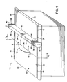
FIGURE 1 is a front perspective view of a table saw, rip fence, and front and rear sensor assemblies ; -
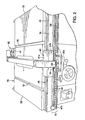
FIG. 2 is a front perspective view of a table saw and rip fence ; -
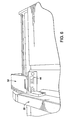
FIG. 3 is a side perspective view of a front sensor assembly illustrated in FIG. -
FIG. 4 is a rear perspective view of a table saw, rip fence and rear sensor assembly illustrated inFIG. 2 ; -
FIG. 5 is a side perspective view of the table saw, rip fence and rear sensor assembly illustrated inFIG. 2 ; -
FIG. 6 is a front perspective view of the rear sensor assembly according toFIG. 2 ; -
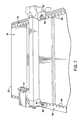
FIG. 7 is a front perspective view of a table saw, rip fence, and front and rear sensor assemblies -
FIG. 8 is a front perspective view of a table saw and rip fence ; -
FIG. 9 is a side perspective view of the front sensor assembly illustrated inFIG. 8 ; and -
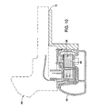
FIG. 10 is a side sectional view of the table saw and rip fence illustrated inFIG. 8 . - One exemplary table saw assembly, indicated generally at 10, is illustrated in
FIG. 1 in connection with a first embodiment of the invention. InFIG. 1 , arotary cutting blade 12 extends upwardly through ablade bracket 14, which is an elongated slot disposed in a generally middle portion of a table 16. A pair of miter gauge slots 18 (best shown inFIG. 2 ) are also preferably provided, one on each side of theblade bracket 14, and extending from afront end 20 of the table 16 to arear end 22 of the table. While therotary cutting blade 12 may be tiltable for miter cutting, aradial plane 24 of therotary cutting blade 12 generally extends perpendicularly with respect to a plane of the table. - An elongated, generally rectangular rip fence, indicated generally at 26, is also provided with the exemplary
table saw assembly 10, wherein the rip fence has a length corresponding generally to a length of the table 16, which is defined as a depth of the table as measured from thefront end 20 to therear end 22 of the table. Therip fence 26 is configured to be slidable with respect to a top surface of the table 16. Thus, therip fence 26 has afront end 28 that engages thefront end 20 of the table 16 and arear end 30 that engages arear end 22 of the table and has an elongatedrectangular body 32. Therip fence 26 can move along a width of the table between therotary cutting blade 12 and a predetermined location on the table, where the width of the table is defined as extending betweenside ends 33. Aguide plane 34 of therip fence 26 is configured and arranged to face theblade bracket 14. - The table 16 and the
rip fence 26 include complementary measurement mechanisms whereby a distance from theradial plane 24 of therotary cutting blade 12 to a predetermined location on the table may be accurately and precisely measured, and whereby parallelism between the radial plane and therip fence 26 may be accurately and precisely ascertained to promote accurate and precise cutting. Therip fence 26 includes one or more of a plurality of positional sensing mechanisms for sensing and/or displaying a location of therip fence 26 relative to a predetermined reference point, such as therotary cutting blade 12. The sensing mechanisms may include, but should not be construed as being limited to, electronic sensors, digital readouts, pointers, or measurement indicia such as scoring or other markings disposed on therip fence 26 at the front andrear ends rip fence 26, such as electronic indicators, digital readouts, pointers or measurement indicia to reference or communicate with the rip fence to give visual or other indication to an operator as to the position of the rip fence relative to the blade. - For example, turning again to
FIG. 1 , therip fence 26 includes a front sensor assembly, indicated generally at 36, and a rear sensor assembly, indicated generally at 38, each of which preferably includes apositional sensor 40. At least oneLCD screen 44 is preferably provided to indicate a variety of parameters, such as displacement of therip fence 26 from therotary cutting blade 12 and the parallelism of the rip fence to the rotary cutting blade. Thepositional sensors 40 may be one of a plurality of mechanisms, such as an optical reflective reader, a capacitor, a magnet, or a pointing device, to name a few. -
FIG. 1 illustrates the front and rearpositional sensors 40 to be optical reflective readers. The table 16 correspondingly includes positional indicators, such as a plurality ofsensor reference points 46, which may be sensed by the respectivepositional sensors 40.Sensor reference points 46 may include one of a plurality of mechanisms, such as a strip of electrical contacts to be read by thepositional sensors 40, magnets, a series of bar codes disposed at predetermined increments (e.g. 0.40 mm (1/64")), or contrasting stripes to be read by an optical reflective reader, to name a few. - As illustrated in
FIG. 1 , thesensor reference points 46 include a strip having a plurality of contrasting stripes, wherein the stripes have a predetermined width, preferably 1.6 mm (1/16"). A predetermined number of sensors disposed within each of the contrasting stripes, preferably four, electronically divide the contrasting stripes, thereby rendering an enhanced resolution. For example, where four sensors are included in each of the contrasting stripes gives a resolution of 0.40mm (1/64"). - In contrast,
FIG. 2 illustrates another table saw whereby the positional sensors include positional transducer sensinghead 47a and interactingstrip 47b, which may be optical, mechanical magnetic or capacitive, to name a few. Alternatively, a string driven positional transducer (not shown) may also be used. For example, a capacitive-based interacting strip would have a series of copper pads at equal intervals such as 3.2 mm, (1/8") shown asitem 46 onitem 47b. - The table 16 also preferably includes structural features that promote sliding of the
rip fence 26 along the surface of the table 16. These features are commonly known in the art, and include rails on which the fence can slide. Additional structural features may be provided to promote sliding of thepositional sensors 40 with therip fence 26. - For example, turning again to
FIGS. 2-5 , the table 16 may also include front and rear slidingbrackets rear ends sides 33 of the table, for purposes of convention. Depending on the particular sensor assembly used with the table, thesliding brackets rip fence 26, and reciprocate along the respective front and rear slidingbrackets - Turning to the front sliding
bracket 48 of the table saw illustrated inFIGs. 2 and3 , the front sliding bracket is generally rectangular in shape, having a length extending betweensides 33 of the table 16, with anoutside surface 56 including alongitudinal slot 58 therein. Alower portion 60 of the front slidingbracket 48 depends downwardly from a top surface of the table 16, and thefront sensor assembly 36 is coupled to the lower portion of the front slidingbracket 48 such that the front sensor assembly is lower than the top surface of the table 16, while therip fence 26 is coupled to an upper portion of the front sliding bracket, thereby operatively coupling the rip fence and the front sensor assembly. Thus, thefront sensor assembly 36 moves along thelongitudinal slot 58 as therip fence 26 moves along a surface of the table 16. - A front mounting bracket, designated generally at 61, is preferably provided to couple the
rip fence 26 to the front slidingbracket 48. The front mountingbracket 61 includes includes a generallyhorizontal portion 61a and a generallyvertical portion 61b disposed at right angles to one another to receive the generally rectangular slidingbracket 48 therein. The front mountingbracket 61 is thereby operably coupled to both therip fence 26 and the slidingbracket 48, and may slidably engage the sliding bracket to promote movement of the rip fence along the width of the table 16. - Similarly, the
rear sensor assembly 38, which is best illustrated inFIGs. 4 and5 , is also operatively coupled to therip fence 26 such that as the rip fence moves, the rear sensor assembly moves. Specifically, the rear sliding bracket 50 (best shown inFIGs. 4 and5 ) includes a slidingrail 62 that is coupled to an extremerear end 22 of the table 16 and is vertically displaced from the top surface of the table to be elevationally lower than the top surface of the table. A mountingbracket 64 is mounted to the slidingrail 62 and configured to be slidingly engaged thereto. - The mounting
bracket 64 is preferably generally rectangular in shape, with alongitudinal groove 66 extending along a top portion thereof. Therip fence 26 is mounted to the mountingbracket 64, preferably via a mountingextension 68 having a downwardly dependingfastening element 70, such as a pin, configured to lockingly engage thelongitudinal groove 66. Similarly, therear sensor assembly 38 is coupled to the mountingextension 68 on a mountingside 72 thereof, and a lowerrear end portion 74 is lockingly engaged to the mountingbracket 64. - Thus, the
rear sensor assembly 38 is operably coupled to both therip fence 26 and the mountingbracket 64 such that the rear sensor assembly moves with the rip fence as it moves. Thepositional sensor 40 is disposed at a right hand side of therear sensor assembly 38 as viewed inFIG. 3 . - In
FIG. 1 , asingle LCD screen 44 is configured and arranged on a top surface of therip fence 26, whereas alternatively LCD screens 44 may be disposed at each of the front andrear sensor assemblies FIGs 2 and3 , where LCD screens are provided on each of the front andrear sensor assemblies - Thus, in operation the
rip fence 26 is brought into abutment with theradial plane 24 or other predetermined position, at which point the sensors are zeroed by activating a zeroingmechanism 76 disposed on the rip fence. The operator may then move therip fence 26 to a predetermined location at a desired distance from therotary cutting blade 12, and may determine the distance from the blade by reading the one ormore LCD screens 44 disposed within the front andrear sensor assemblies rip fence 26 itself. The distance of therip fence 26 from therotary cutting blade 12 is an average of the respective distances of each of thepositional sensors 40, which may be expressed as follows: (x1 + x2)/2, where x1 is a displacement of a first positional sensor and x2 is a displacement of a second positional sensor. - Parallelism, on the other hand, may be determined by the absolute value of the difference between x1 and x2 as follows: |x1- x2|. Once the operator knows the parallelism, the operator may readjust the fence to resolve any discrepancy such that the absolute value of the difference between x1 and x2 approaches zero, indicating parallelism of the
rip fence 26 with therotary cutting blade 12. A locking mechanism, such as a clampinglever 79 disposed at thefront end 28 of therip fence 26, may then be pivoted into a locking position to lock the rip fence into position. -
FIG. 7 illustrates yet another table saw that includes arip fence 26 wherein thepositional sensors 40 consist of physical indicators, such aspointers 80 disposed at each end of a mountingbracket 82 coupled to the rip fence. Correspondingly, top surfaces of the slidingbrackets measurement indicia 84 at predetermined increments. The measurement indicia 84 on each of the respective slidingbrackets front end 20 to arear end 22. Thus, as therip fence 26 is moved away from therotary cutting blade 12, thepointers 80 will point to a specific measurement such that the operator can readjust and reposition the rip fence until each respective pointer is pointing at the same measurement, indicating a common distance from theradial plane 24 by front andrear ends - Turning now to
FIGs. 9-10 , to promote a greater range of motion for therip fence 26, some table saws also include aside extension 86 that is configured to be extendable in a direction of the right side 54 of the table 16. More specifically, theside extension 86 is typically a slideable panel that is coupled to the table 16 via one or more rails 87. The rails themselves slideably and telescopically extend from the table 16 to thereby move the side extension. Theside extension 86 provides for a predetermined length of extra movement of therip fence 26. - For example, typically the distance from the
radial plane 24 and theguide plane 34 of therip fence 26 reaches a maximum at a predetermined location toward the right end 54 of the table 16, such as between approximately 33 and 46 cm (13 and 18 inches), with restriction placed on further movement by a hard stop (not shown) disposed at theright end 33 of the table, which abuts a right end of the slidingbrackets side extension 86 provides for a predetermined increment of extra movement, such as between approximately 28 and 51 cm (11 and 20 inches). - In operation, the operator would slide the
rip fence 26 to an extreme rightward position, at which point the operator would extend theslide extension 86 away from the table 16 to provide for an additional length of movement. However, because therip fence 26 is no longer moving relative to the table 16 as theslide extension 86 is moved, a provision is provided by the invention to promote continued measurement of both the displacement and parallelism of the rip fence. -
Spooled measuring devices 88, such as tape measures, are provided, with a spindle thereof coupled to the table 16 at a the front andrear ends side extension 86 at front and rear ends such that as the side extension is moved, the tape would uncoil to indicate the additional displacement on either side. A disparity in the displacement would indicate a lack of parallelism, which may then be corrected by the operator. - As illustrated in
FIG. 9 for example, the spooledmeasuring device 88 is preferably coupled to the table 16 such that it spools out the measuring tape as the slidingrail 87 moves relative to the table. More particularly, the spooledmeasuring device 88 is coupled to the table 16 via fasteners, preferablybolts 92, where the bolts extend through a length of the mounting block and into the table 16 to secure the mounting block and spooled measuring device to the table. Aslot 94 is provided in the slidingrail 87 such that sliding rail may move relative to thestationary mounting block 90 for a predetermined distance, as a corresponding amount of measuring tape is spooled out from the spooledmeasuring device 88.
Claims (5)
- A power table saw (10) of the type which has a generally rectangular table (16) with front and rear end portions (20, 22), a motor operatively coupled to drive a rotary cutting blade (12) extending upwardly through a top of the table (16), said table saw (10) comprising:an elongated fence (26) having front and rear end portions (28, 30), and being configured to be laterally movable along the width of the table (16) and be secured to the front and rear end portions (20, 22) of the table (16);front and rear releasable locking mechanisms operatively associated with said front and rear end portions (28, 30) of said fence (26) for locking each end portion to the end portions (20, 22) of the table (16) ;at least one positional sensor (40) provided with each of said front and rear end portions of said fence (26) for determining the lateral position of each end portion (28, 30) of said fence (26) along the width of the table (16), anda plurality of positional indicators disposed along a width of the table (16) toward the front and rear portions (20, 22) of the table (16), said positional indicators being configured and arranged to operatively engage said at least one positional sensor (40),characterized in thatthe power table saw (10) further comprises a sliding rail (87) coupled to said table (16) and being slidably moveable therewith, and spooled measuring devices (88) coupled to said table (16) and being configured to spool out a strip of said positional indicators as said sliding rail (87) moves relative to said table (16) .
- The power table saw (10) of claim 1 wherein said positional sensors (40) comprise an optical reflective reader and said plurality of positional indicators comprise a plurality of contrasting stripes that may be sensed by said optical sensors.
- The power table saw (10) of claim 2 wherein each of said plurality of contrasting stripes comprise a plurality of sensors having a predetermined width.
- The power table saw (10) according to one of the foregoing claims wherein said positional sensors (40) comprise capacitors and said plurality of positional indicators comprise a strip of electrical contacts spaced at predetermined intervals.
- The power table saw (10) according to one of the foregoing claims wherein said elongated fence (26) comprises front and rear mounting brackets (61, 64) for slidably mounting said elongated fence (26) to the table (16) .
Applications Claiming Priority (2)
| Application Number | Priority Date | Filing Date | Title |
|---|---|---|---|
| US60604004P | 2004-08-31 | 2004-08-31 | |
| PCT/US2005/030671 WO2006026551A1 (en) | 2004-08-31 | 2005-08-29 | Rip fence for a table saw |
Publications (2)
| Publication Number | Publication Date |
|---|---|
| EP1784290A1 EP1784290A1 (en) | 2007-05-16 |
| EP1784290B1 true EP1784290B1 (en) | 2012-06-27 |
Family
ID=35447838
Family Applications (1)
| Application Number | Title | Priority Date | Filing Date |
|---|---|---|---|
| EP20050792561 Expired - Lifetime EP1784290B1 (en) | 2004-08-31 | 2005-08-29 | Rip fence for a table saw |
Country Status (6)
| Country | Link |
|---|---|
| US (1) | US7614330B2 (en) |
| EP (1) | EP1784290B1 (en) |
| CN (1) | CN101010176B (en) |
| CA (1) | CA2577902A1 (en) |
| TW (1) | TWI359066B (en) |
| WO (1) | WO2006026551A1 (en) |
Families Citing this family (26)
| Publication number | Priority date | Publication date | Assignee | Title |
|---|---|---|---|---|
| DE102006041756A1 (en) * | 2006-09-04 | 2008-03-06 | Robert Bosch Gmbh | Machine tool monitoring device |
| US7735403B2 (en) * | 2006-09-26 | 2010-06-15 | Robert Bosch Gmbh | Alignment system for a fence for a table saw |
| CN101758563B (en) | 2008-10-30 | 2012-05-30 | 苏州宝时得电动工具有限公司 | Bench saw |
| US8776384B2 (en) * | 2010-02-24 | 2014-07-15 | Robert Bosch Gmbh | Line of sight depth of cut scale |
| US20110296968A1 (en) * | 2010-06-02 | 2011-12-08 | Robert Bosch Gmbh | Feedback mechanism for adjustable miter fence |
| US9221188B1 (en) * | 2010-10-07 | 2015-12-29 | Dennis R. Wisen | Precision positioning of a fence |
| TW201242735A (en) * | 2011-04-19 | 2012-11-01 | Ren-Wen Zhang | Plate size measurement and processing method |
| CN102756407B (en) * | 2011-04-28 | 2015-03-25 | 张仁文 | Plate size measurement and processing methods |
| US8991806B2 (en) | 2012-04-19 | 2015-03-31 | John Matthew Meyer | Extension table assembly for power tools |
| US9592623B2 (en) | 2012-12-26 | 2017-03-14 | Robert Bosch Tool Corporation | Rip fence having dual adjustment for a power tool |
| CN104646750B (en) * | 2013-11-20 | 2017-08-11 | 力山工业股份有限公司 | Table saw machine with sawing size indication device |
| CN104044188B (en) * | 2014-06-10 | 2016-01-20 | 江门市南洋船舶工程有限公司 | For the positioner of wood sawing machine fly-cutting lath |
| CN104441067B (en) * | 2014-10-21 | 2016-09-07 | 德清县兴拓木板厂(普通合伙) | A kind of high intensity wood material cutting machine |
| US9731432B1 (en) * | 2016-03-28 | 2017-08-15 | Chin-Chin Chang | Rip fence with locking device |
| CN105965607A (en) * | 2016-07-27 | 2016-09-28 | 武侯区华聚家私经营部 | Clamping device for woodworking pushing bench saw |
| US10576653B2 (en) * | 2016-08-05 | 2020-03-03 | Robert Bosch Tool Corporation | Rip fence having micro-adjustment for a power tool |
| US10703007B2 (en) * | 2018-04-06 | 2020-07-07 | Robert Bosch Tool Corporation | Stop mechanism for a table saw and method of using the same |
| US11095153B2 (en) | 2019-03-15 | 2021-08-17 | Ossia Inc. | Wireless power system technology implemented in lighting infrastructure |
| DE202019101777U1 (en) * | 2019-03-28 | 2020-07-03 | Altendorf Gmbh | Woodworking machine with a releasable rip fence |
| US11642810B2 (en) * | 2019-05-01 | 2023-05-09 | Barry Douglas Wixey | Adjustable fence mounting assembly for a table saw |
| US11298762B2 (en) * | 2019-07-18 | 2022-04-12 | Lawrence Rhodes | Table saw and miter saw combination apparatus |
| TWI723655B (en) * | 2019-11-29 | 2021-04-01 | 萬代利機械股份有限公司 | Adjusting and positioning structure of circular sawing machine feeding by board |
| US11312037B2 (en) * | 2019-12-09 | 2022-04-26 | Timothy Owens | Miter fence positioner |
| DE202020104817U1 (en) * | 2020-08-19 | 2021-11-26 | Otto Martin Maschinenbau Gmbh & Co. Kg | Safety architecture for woodworking machines |
| CN112720662A (en) * | 2020-12-14 | 2021-04-30 | 九江中科鑫星新材料有限公司 | Processing equipment of ultra-high molecular polyethylene pipe |
| CN115176718A (en) * | 2022-08-01 | 2022-10-14 | 河南牧业经济学院 | Wild simulated donkey breeding ring |
Family Cites Families (17)
| Publication number | Priority date | Publication date | Assignee | Title |
|---|---|---|---|---|
| US3734151A (en) * | 1970-09-21 | 1973-05-22 | H Skripsky | Portable workbench |
| US3963279A (en) * | 1975-08-14 | 1976-06-15 | Loyd W. Richardson Construction Company | Movable guide bar |
| US4961269A (en) * | 1988-08-19 | 1990-10-09 | Delta International Machinery Corporation | Bi-directional direct read measurement system |
| US4982509A (en) * | 1988-08-19 | 1991-01-08 | Delta International Machinery Corp. | Measurement system having multiple display orientations |
| US5406715A (en) * | 1992-07-07 | 1995-04-18 | Mitutoyo Corporation | Tape measure device |
| US5327653A (en) * | 1992-08-19 | 1994-07-12 | Pistorius Robert T | Miter linear measurement gage |
| DE19637170A1 (en) * | 1996-09-12 | 1998-03-26 | Ant Panhans Werkzeug Masch | Stop system for a circular saw |
| TW494057B (en) * | 1999-06-09 | 2002-07-11 | Sb Power Tool Co | Table saw and rip fence for use with a table saw |
| US6725755B1 (en) | 1999-06-15 | 2004-04-27 | S-B Power Tool Company | Scale system for use with a movable table |
| US6986370B1 (en) | 2000-02-01 | 2006-01-17 | Home Depot U.S.A., Inc. | Table saw |
| GB2359040A (en) | 2000-02-09 | 2001-08-15 | Geoffrey Manning | A transportable workbench |
| DE60106670D1 (en) * | 2000-05-24 | 2004-12-02 | Prec Automation Inc | System for coupling a control device and the guide rail of a saw table |
| US6647847B2 (en) | 2001-02-15 | 2003-11-18 | Htc Products, Inc. | Fence |
| SG118084A1 (en) | 2001-08-24 | 2006-01-27 | Micron Technology Inc | Method and apparatus for cutting semiconductor wafers |
| US6776076B2 (en) * | 2002-11-21 | 2004-08-17 | Mario A. Salazar | Angle gauge |
| US6899006B2 (en) * | 2003-09-04 | 2005-05-31 | Robert M. Jolkovski | Miter saw measuring fence |
| US7231858B2 (en) * | 2004-04-13 | 2007-06-19 | Robert Bosch Gmbh | Table saw having a measurement and display system |
-
2005
- 2005-08-29 CN CN2005800293069A patent/CN101010176B/en not_active Expired - Fee Related
- 2005-08-29 US US11/214,356 patent/US7614330B2/en not_active Expired - Fee Related
- 2005-08-29 EP EP20050792561 patent/EP1784290B1/en not_active Expired - Lifetime
- 2005-08-29 WO PCT/US2005/030671 patent/WO2006026551A1/en not_active Ceased
- 2005-08-29 CA CA 2577902 patent/CA2577902A1/en not_active Abandoned
- 2005-08-31 TW TW94129825A patent/TWI359066B/en not_active IP Right Cessation
Also Published As
| Publication number | Publication date |
|---|---|
| TWI359066B (en) | 2012-03-01 |
| US7614330B2 (en) | 2009-11-10 |
| TW200618970A (en) | 2006-06-16 |
| US20060065087A1 (en) | 2006-03-30 |
| CN101010176A (en) | 2007-08-01 |
| CN101010176B (en) | 2012-09-26 |
| EP1784290A1 (en) | 2007-05-16 |
| WO2006026551A1 (en) | 2006-03-09 |
| CA2577902A1 (en) | 2006-03-09 |
Similar Documents
| Publication | Publication Date | Title |
|---|---|---|
| US7614330B2 (en) | Rip fence for a table saw | |
| EP1586429B1 (en) | Table saw having a measurement and display system | |
| US6786122B2 (en) | Scale system for use with a movable table | |
| US5491907A (en) | Multi-functional gauge | |
| US5327653A (en) | Miter linear measurement gage | |
| US4945651A (en) | Apparatus for measuring length | |
| US4557170A (en) | Workpiece saw cutoff length measuring device | |
| WO2007111870A2 (en) | Precision electronic combination square | |
| US20040226179A1 (en) | Saw guide for use with lined sheet material | |
| US12202063B2 (en) | System and method for efficient material measurement and conversion | |
| US4908953A (en) | Length measuring device for milling machines, sawing machines and similar machines | |
| US20230140756A1 (en) | Precision cutting guide system | |
| US8522445B1 (en) | Marking gauge for electronic measurement and display | |
| CN115014141A (en) | Multifunctional measuring scale | |
| US11731306B1 (en) | Push block safe index scale | |
| EP1695026A1 (en) | An apparatus for calibrating a measuring instrument | |
| US6510618B2 (en) | Angle gage | |
| EP1964643A1 (en) | Systems and methods for measuring height of jointer infeed surface | |
| US20060174502A1 (en) | Linear and angular measuring apparatus | |
| KR101447327B1 (en) | Angle meter equipped two bar plate | |
| US5533273A (en) | Angle milling indicator | |
| CN222865860U (en) | Thickness measuring equipment | |
| CN101332610B (en) | Woodworker planer input surface height measuring system and method | |
| US20030140748A1 (en) | Mat cutter with precision stops | |
| US20080098867A1 (en) | Workpiece support device for power saws |
Legal Events
| Date | Code | Title | Description |
|---|---|---|---|
| PUAI | Public reference made under article 153(3) epc to a published international application that has entered the european phase |
Free format text: ORIGINAL CODE: 0009012 |
|
| 17P | Request for examination filed |
Effective date: 20070308 |
|
| AK | Designated contracting states |
Kind code of ref document: A1 Designated state(s): DE FR GB IT |
|
| RIN1 | Information on inventor provided before grant (corrected) |
Inventor name: GRISWOLD, SCOTT Inventor name: SVETLIK, KENNETH, N. Inventor name: VORUGANTI, RAVI Inventor name: WOLF, BRADLEY Inventor name: TAM, RAMON Inventor name: TALESKY, MARK, S. |
|
| DAX | Request for extension of the european patent (deleted) | ||
| RBV | Designated contracting states (corrected) |
Designated state(s): DE FR GB IT |
|
| 17Q | First examination report despatched |
Effective date: 20090102 |
|
| R17C | First examination report despatched (corrected) |
Effective date: 20090105 |
|
| GRAP | Despatch of communication of intention to grant a patent |
Free format text: ORIGINAL CODE: EPIDOSNIGR1 |
|
| RIN1 | Information on inventor provided before grant (corrected) |
Inventor name: GRISWOLD, SCOTT Inventor name: TAM, RAMON Inventor name: WOLF, BRADLEY Inventor name: VORUGANTI, RAVI Inventor name: SVETLIK, KENNETH, N. Inventor name: TALESKY, MARK, S. |
|
| GRAS | Grant fee paid |
Free format text: ORIGINAL CODE: EPIDOSNIGR3 |
|
| GRAA | (expected) grant |
Free format text: ORIGINAL CODE: 0009210 |
|
| AK | Designated contracting states |
Kind code of ref document: B1 Designated state(s): DE FR GB IT |
|
| REG | Reference to a national code |
Ref country code: GB Ref legal event code: FG4D |
|
| REG | Reference to a national code |
Ref country code: DE Ref legal event code: R096 Ref document number: 602005034959 Country of ref document: DE Effective date: 20120823 |
|
| PGFP | Annual fee paid to national office [announced via postgrant information from national office to epo] |
Ref country code: GB Payment date: 20120823 Year of fee payment: 8 |
|
| PGFP | Annual fee paid to national office [announced via postgrant information from national office to epo] |
Ref country code: FR Payment date: 20120831 Year of fee payment: 8 |
|
| PGFP | Annual fee paid to national office [announced via postgrant information from national office to epo] |
Ref country code: IT Payment date: 20120824 Year of fee payment: 8 |
|
| PLBE | No opposition filed within time limit |
Free format text: ORIGINAL CODE: 0009261 |
|
| STAA | Information on the status of an ep patent application or granted ep patent |
Free format text: STATUS: NO OPPOSITION FILED WITHIN TIME LIMIT |
|
| 26N | No opposition filed |
Effective date: 20130328 |
|
| REG | Reference to a national code |
Ref country code: DE Ref legal event code: R097 Ref document number: 602005034959 Country of ref document: DE Effective date: 20130328 |
|
| GBPC | Gb: european patent ceased through non-payment of renewal fee |
Effective date: 20130829 |
|
| REG | Reference to a national code |
Ref country code: FR Ref legal event code: ST Effective date: 20140430 |
|
| PG25 | Lapsed in a contracting state [announced via postgrant information from national office to epo] |
Ref country code: IT Free format text: LAPSE BECAUSE OF NON-PAYMENT OF DUE FEES Effective date: 20130829 |
|
| PG25 | Lapsed in a contracting state [announced via postgrant information from national office to epo] |
Ref country code: GB Free format text: LAPSE BECAUSE OF NON-PAYMENT OF DUE FEES Effective date: 20130829 |
|
| PG25 | Lapsed in a contracting state [announced via postgrant information from national office to epo] |
Ref country code: FR Free format text: LAPSE BECAUSE OF NON-PAYMENT OF DUE FEES Effective date: 20130902 |
|
| PGFP | Annual fee paid to national office [announced via postgrant information from national office to epo] |
Ref country code: DE Payment date: 20191021 Year of fee payment: 15 |
|
| REG | Reference to a national code |
Ref country code: DE Ref legal event code: R119 Ref document number: 602005034959 Country of ref document: DE |
|
| PG25 | Lapsed in a contracting state [announced via postgrant information from national office to epo] |
Ref country code: DE Free format text: LAPSE BECAUSE OF NON-PAYMENT OF DUE FEES Effective date: 20210302 |