EP1784235B1 - Liquid dispensing device - Google Patents
Liquid dispensing device Download PDFInfo
- Publication number
- EP1784235B1 EP1784235B1 EP05794231A EP05794231A EP1784235B1 EP 1784235 B1 EP1784235 B1 EP 1784235B1 EP 05794231 A EP05794231 A EP 05794231A EP 05794231 A EP05794231 A EP 05794231A EP 1784235 B1 EP1784235 B1 EP 1784235B1
- Authority
- EP
- European Patent Office
- Prior art keywords
- chamber
- dispensing device
- liquid dispensing
- closure
- liquid
- Prior art date
- Legal status (The legal status is an assumption and is not a legal conclusion. Google has not performed a legal analysis and makes no representation as to the accuracy of the status listed.)
- Expired - Fee Related
Links
- 239000007788 liquid Substances 0.000 title claims abstract description 41
- 230000000717 retained effect Effects 0.000 claims abstract description 12
- 229910001285 shape-memory alloy Inorganic materials 0.000 claims description 7
- 238000001802 infusion Methods 0.000 description 5
- 239000012530 fluid Substances 0.000 description 3
- 238000010276 construction Methods 0.000 description 2
- 239000006071 cream Substances 0.000 description 2
- 239000003814 drug Substances 0.000 description 2
- 229940079593 drug Drugs 0.000 description 2
- 230000005684 electric field Effects 0.000 description 2
- NOESYZHRGYRDHS-UHFFFAOYSA-N insulin Chemical compound N1C(=O)C(NC(=O)C(CCC(N)=O)NC(=O)C(CCC(O)=O)NC(=O)C(C(C)C)NC(=O)C(NC(=O)CN)C(C)CC)CSSCC(C(NC(CO)C(=O)NC(CC(C)C)C(=O)NC(CC=2C=CC(O)=CC=2)C(=O)NC(CCC(N)=O)C(=O)NC(CC(C)C)C(=O)NC(CCC(O)=O)C(=O)NC(CC(N)=O)C(=O)NC(CC=2C=CC(O)=CC=2)C(=O)NC(CSSCC(NC(=O)C(C(C)C)NC(=O)C(CC(C)C)NC(=O)C(CC=2C=CC(O)=CC=2)NC(=O)C(CC(C)C)NC(=O)C(C)NC(=O)C(CCC(O)=O)NC(=O)C(C(C)C)NC(=O)C(CC(C)C)NC(=O)C(CC=2NC=NC=2)NC(=O)C(CO)NC(=O)CNC2=O)C(=O)NCC(=O)NC(CCC(O)=O)C(=O)NC(CCCNC(N)=N)C(=O)NCC(=O)NC(CC=3C=CC=CC=3)C(=O)NC(CC=3C=CC=CC=3)C(=O)NC(CC=3C=CC(O)=CC=3)C(=O)NC(C(C)O)C(=O)N3C(CCC3)C(=O)NC(CCCCN)C(=O)NC(C)C(O)=O)C(=O)NC(CC(N)=O)C(O)=O)=O)NC(=O)C(C(C)CC)NC(=O)C(CO)NC(=O)C(C(C)O)NC(=O)C1CSSCC2NC(=O)C(CC(C)C)NC(=O)C(NC(=O)C(CCC(N)=O)NC(=O)C(CC(N)=O)NC(=O)C(NC(=O)C(N)CC=1C=CC=CC=1)C(C)C)CC1=CN=CN1 NOESYZHRGYRDHS-UHFFFAOYSA-N 0.000 description 2
- 102000004877 Insulin Human genes 0.000 description 1
- 108090001061 Insulin Proteins 0.000 description 1
- 230000001934 delay Effects 0.000 description 1
- 238000001514 detection method Methods 0.000 description 1
- 238000012377 drug delivery Methods 0.000 description 1
- 239000013536 elastomeric material Substances 0.000 description 1
- 230000009969 flowable effect Effects 0.000 description 1
- 238000002347 injection Methods 0.000 description 1
- 239000007924 injection Substances 0.000 description 1
- 229940125396 insulin Drugs 0.000 description 1
- 239000000463 material Substances 0.000 description 1
- 239000006072 paste Substances 0.000 description 1
- 239000012858 resilient material Substances 0.000 description 1
- 239000000126 substance Substances 0.000 description 1
- 239000000725 suspension Substances 0.000 description 1
Images


Classifications
-
- A—HUMAN NECESSITIES
- A61—MEDICAL OR VETERINARY SCIENCE; HYGIENE
- A61M—DEVICES FOR INTRODUCING MEDIA INTO, OR ONTO, THE BODY; DEVICES FOR TRANSDUCING BODY MEDIA OR FOR TAKING MEDIA FROM THE BODY; DEVICES FOR PRODUCING OR ENDING SLEEP OR STUPOR
- A61M5/00—Devices for bringing media into the body in a subcutaneous, intra-vascular or intramuscular way; Accessories therefor, e.g. filling or cleaning devices, arm-rests
- A61M5/14—Infusion devices, e.g. infusing by gravity; Blood infusion; Accessories therefor
- A61M5/142—Pressure infusion, e.g. using pumps
- A61M5/14244—Pressure infusion, e.g. using pumps adapted to be carried by the patient, e.g. portable on the body
-
- A—HUMAN NECESSITIES
- A61—MEDICAL OR VETERINARY SCIENCE; HYGIENE
- A61M—DEVICES FOR INTRODUCING MEDIA INTO, OR ONTO, THE BODY; DEVICES FOR TRANSDUCING BODY MEDIA OR FOR TAKING MEDIA FROM THE BODY; DEVICES FOR PRODUCING OR ENDING SLEEP OR STUPOR
- A61M5/00—Devices for bringing media into the body in a subcutaneous, intra-vascular or intramuscular way; Accessories therefor, e.g. filling or cleaning devices, arm-rests
- A61M5/14—Infusion devices, e.g. infusing by gravity; Blood infusion; Accessories therefor
- A61M5/142—Pressure infusion, e.g. using pumps
- A61M5/145—Pressure infusion, e.g. using pumps using pressurised reservoirs, e.g. pressurised by means of pistons
-
- B—PERFORMING OPERATIONS; TRANSPORTING
- B01—PHYSICAL OR CHEMICAL PROCESSES OR APPARATUS IN GENERAL
- B01L—CHEMICAL OR PHYSICAL LABORATORY APPARATUS FOR GENERAL USE
- B01L3/00—Containers or dishes for laboratory use, e.g. laboratory glassware; Droppers
- B01L3/02—Burettes; Pipettes
- B01L3/0241—Drop counters; Drop formers
-
- B—PERFORMING OPERATIONS; TRANSPORTING
- B01—PHYSICAL OR CHEMICAL PROCESSES OR APPARATUS IN GENERAL
- B01L—CHEMICAL OR PHYSICAL LABORATORY APPARATUS FOR GENERAL USE
- B01L3/00—Containers or dishes for laboratory use, e.g. laboratory glassware; Droppers
- B01L3/02—Burettes; Pipettes
- B01L3/0241—Drop counters; Drop formers
- B01L3/0265—Drop counters; Drop formers using valves to interrupt or meter fluid flow, e.g. using solenoids or metering valves
-
- B—PERFORMING OPERATIONS; TRANSPORTING
- B01—PHYSICAL OR CHEMICAL PROCESSES OR APPARATUS IN GENERAL
- B01L—CHEMICAL OR PHYSICAL LABORATORY APPARATUS FOR GENERAL USE
- B01L3/00—Containers or dishes for laboratory use, e.g. laboratory glassware; Droppers
- B01L3/02—Burettes; Pipettes
- B01L3/0241—Drop counters; Drop formers
- B01L3/0268—Drop counters; Drop formers using pulse dispensing or spraying, eg. inkjet type, piezo actuated ejection of droplets from capillaries
-
- G—PHYSICS
- G01—MEASURING; TESTING
- G01F—MEASURING VOLUME, VOLUME FLOW, MASS FLOW OR LIQUID LEVEL; METERING BY VOLUME
- G01F11/00—Apparatus requiring external operation adapted at each repeated and identical operation to measure and separate a predetermined volume of fluid or fluent solid material from a supply or container, without regard to weight, and to deliver it
- G01F11/02—Apparatus requiring external operation adapted at each repeated and identical operation to measure and separate a predetermined volume of fluid or fluent solid material from a supply or container, without regard to weight, and to deliver it with measuring chambers which expand or contract during measurement
- G01F11/08—Apparatus requiring external operation adapted at each repeated and identical operation to measure and separate a predetermined volume of fluid or fluent solid material from a supply or container, without regard to weight, and to deliver it with measuring chambers which expand or contract during measurement of the diaphragm or bellows type
-
- G—PHYSICS
- G01—MEASURING; TESTING
- G01F—MEASURING VOLUME, VOLUME FLOW, MASS FLOW OR LIQUID LEVEL; METERING BY VOLUME
- G01F11/00—Apparatus requiring external operation adapted at each repeated and identical operation to measure and separate a predetermined volume of fluid or fluent solid material from a supply or container, without regard to weight, and to deliver it
- G01F11/02—Apparatus requiring external operation adapted at each repeated and identical operation to measure and separate a predetermined volume of fluid or fluent solid material from a supply or container, without regard to weight, and to deliver it with measuring chambers which expand or contract during measurement
- G01F11/08—Apparatus requiring external operation adapted at each repeated and identical operation to measure and separate a predetermined volume of fluid or fluent solid material from a supply or container, without regard to weight, and to deliver it with measuring chambers which expand or contract during measurement of the diaphragm or bellows type
- G01F11/082—Apparatus requiring external operation adapted at each repeated and identical operation to measure and separate a predetermined volume of fluid or fluent solid material from a supply or container, without regard to weight, and to deliver it with measuring chambers which expand or contract during measurement of the diaphragm or bellows type of the squeeze container type
-
- A—HUMAN NECESSITIES
- A61—MEDICAL OR VETERINARY SCIENCE; HYGIENE
- A61M—DEVICES FOR INTRODUCING MEDIA INTO, OR ONTO, THE BODY; DEVICES FOR TRANSDUCING BODY MEDIA OR FOR TAKING MEDIA FROM THE BODY; DEVICES FOR PRODUCING OR ENDING SLEEP OR STUPOR
- A61M2205/00—General characteristics of the apparatus
- A61M2205/02—General characteristics of the apparatus characterised by a particular materials
- A61M2205/0266—Shape memory materials
-
- B—PERFORMING OPERATIONS; TRANSPORTING
- B01—PHYSICAL OR CHEMICAL PROCESSES OR APPARATUS IN GENERAL
- B01L—CHEMICAL OR PHYSICAL LABORATORY APPARATUS FOR GENERAL USE
- B01L2400/00—Moving or stopping fluids
- B01L2400/04—Moving fluids with specific forces or mechanical means
- B01L2400/0403—Moving fluids with specific forces or mechanical means specific forces
- B01L2400/0433—Moving fluids with specific forces or mechanical means specific forces vibrational forces
- B01L2400/0439—Moving fluids with specific forces or mechanical means specific forces vibrational forces ultrasonic vibrations, vibrating piezo elements
-
- B—PERFORMING OPERATIONS; TRANSPORTING
- B01—PHYSICAL OR CHEMICAL PROCESSES OR APPARATUS IN GENERAL
- B01L—CHEMICAL OR PHYSICAL LABORATORY APPARATUS FOR GENERAL USE
- B01L2400/00—Moving or stopping fluids
- B01L2400/04—Moving fluids with specific forces or mechanical means
- B01L2400/0475—Moving fluids with specific forces or mechanical means specific mechanical means and fluid pressure
- B01L2400/0478—Moving fluids with specific forces or mechanical means specific mechanical means and fluid pressure pistons
-
- B—PERFORMING OPERATIONS; TRANSPORTING
- B01—PHYSICAL OR CHEMICAL PROCESSES OR APPARATUS IN GENERAL
- B01L—CHEMICAL OR PHYSICAL LABORATORY APPARATUS FOR GENERAL USE
- B01L2400/00—Moving or stopping fluids
- B01L2400/06—Valves, specific forms thereof
- B01L2400/0605—Valves, specific forms thereof check valves
Definitions
- This invention relates to a liquid dispensing device and, in particular, to a device that can be used in drug delivery infusion, or in consumer dispensing products for the metered dispensing of materials such as pastes or creams. It can also be used in microfluidic applications.
- infusion devices delivering drugs, such as insulin
- a motor driven syringe This principle has been known since at least 1976.
- These systems employ an encoded motor, a reduction gear box and a lead screw to drive a plunger along the bore of a reservoir. The plunger in turn forces liquid out of the reservoir.
- the systems are relatively complex, expensive and large. The size and weight of these systems has thus far prohibited the development of a skin worn delivery device.
- the infusion site is linked via a length of tubing to a separate unit carried in the pocket or on the belt of the user. This length of tubing introduces volumetric compliance issues, occlusion detection delays and substantially increases the time taken to prime the system.
- separating the infusion site from the delivery device in this way makes the system far more cumbersome in use.
- the present invention aims to provide a liquid dispensing device which overcomes the above problems and which can be produced in a sufficiently small size that it can be worn on the skin.
- such a device is characterised in that the flexible element upon actuation, is caused to extend into the chamber reducing its volume and thereby causing liquid to be expelled from the chamber through the valve, wherein, when actuation is stopped, the closure is caused to slide in the chamber so as to reduce the volume of the chamber by the amount of the dispensed liquid.
- the present invention as claimed provides a liquid dispensing device which can be manufactured in a sufficiently small size such that it can be worn on the skin close to the injection site, thereby removing the need for lengthy tubes.
- the present invention ensures that the complexity and weight of the device is considerably reduced.
- liquid covers creams, pastes, suspensions and any other flowable substance.
- the flexible element may be a diaphragm or other suitable thin construction, typically formed from an elastomeric material such as rubber.
- the actuator may be mounted on the flexible element.
- the actuator may be connected to a microprocessor or other programmable control device, so that the operation of the actuator can be precisely controlled.
- a control device would also permit the device to be operated automatically, i.e. without regular supervision by a doctor, nurse or the like.
- the chamber may have a reduced diameter portion adjacent the valve.
- the actuator includes a piezoelectric element.
- the piezoelectric element is preferably arranged such that, upon actuation, the flexible element extends only into the chamber and that, when actuation is stopped, it returns to its normal non-extended state.
- the flexible element may be the piezoelectric element itself or may include the piezoelectric element as a part of its construction.
- the actuator includes a shape-memory alloy element which is preferably connected to the flexible element.
- the shape-memory alloy element is preferably connected to the flexible element by a plurality of hooks.
- the shape-memory alloy element is preferably arranged such that, upon actuation, the flexible element extends only into the chamber and that, when actuation is stopped, it returns to its normal non-extended state.
- Fig. 1 shows a liquid dispensing device 10 having a chamber 11 defined by outer walls 12 and a closure 13.
- the outer walls 12 are shaped so as to define a relatively large cylindrical portion 14, a relatively narrow cylindrical portion 15 and a tapered portion 16 connecting the relatively large and relatively small cylindrical portions.
- the chamber 11 has a first opening 17 and a second opening 18.
- a one-way valve 19 is retained within the first opening to permit fluid flow only out of the chamber 11.
- the closure 13 is retained in the second opening 18 and is provided with a sliding seal 20 between it and the inner surface of the wall 12.
- a volume of liquid (not shown) is retained within the chamber 11 and the closure 13 is placed in contact with the volume of liquid so that there is no free space in the chamber.
- the closure 13 is provided with a flexible element 21 and an actuator (see Figs. 3 and 4 ), such as a piezoelectric element or a shape-memory alloy element.
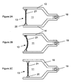
- Fig. 2A shows the device of Fig. 1 in an inactive state.
- the flexible element 13 Upon actuation of the actuator, the flexible element 13 is caused to extend into the chamber 11, as seen in Fig. 2B . This reduces the volume of the chamber 11 and, as a result, a small volume of liquid is thus expelled through the valve 19.
- the pressure within the chamber 11 is reduced, as the flexible element tries to return to its non-extended state and the check valve prevents air from entering the device.
- the difference between the ambient pressure outside the chamber and the lower pressure within the chamber 11 causes the closure 13 to move along the inner surface of the wall 12. This reduces the volume of the chamber 11 and equalizes the pressure within the chamber with the ambient outside pressure.
- the seal 20 slides along the inner surface of the wall 12 such that the closure 13 advances an incremental distance towards the valve 19 and the device is primed for dispensing a further volume of fluid upon further actuation of the actuator.
- Fig. 3 shows one example of a closure for use in the device of Fig. 1 .
- the closure 13 comprises a flexible element 21 which is mounted in a sliding seal 20, thereby closing opening 18.
- An actuator 22, comprising a piezoelectric element, is attached to the flexible element 21.
- an electric field is applied to the piezoelectric element 22, it is caused to contract, thereby reacting against the flexible element 21 and causing the flexible element 21 to extend into the chamber 11.
- the electric field is removed from the piezoelectric element, it returns to its original shape, thereby causing the flexible element to return to its original shape.
- the flexible element 21 may also be resilient and the resilience of the element 21 can assist in returning the piezoelectric element to its original shape.
- FIG. 4 A further example of a closure is shown in Fig. 4 , in which a flexible element 21 is mounted in a sliding seal 20, thereby closing opening 18.
- the actuator consists of a length of shape-memory alloy wire 24, formed into a loop, and secured around a number of hooks 25 which are connected to the flexible element 21.
- a suitable electric current is passed through the wire 24, it contracts in length significantly, thereby causing the hooks 25 to be drawn towards each other and the flexible element to bow into the chamber 11.
- the wire returns to its original length and the flexible element returns to its original shape.
- the flexible element may be resilient, to assist in the return to the original state.
- the liquid dispensing device of the present invention may be provided with one or more elements that engage with the wall 12 of the chamber to prevent, or at least hinder, movement of closure 13 away from the one way valve 19.
- an O-ring 30 may be used, as well as seal 20, and the O-ring may be shaped or formed so as to prevent movement of the closure 13 away from the first opening, i.e. downwards in Fig. 5 .
- one or more barbs 31, typically formed from a resilient material may be provided and which extend from the seal 20 to engage with the inner surface of the wall 12. Movement of the closure towards the first opening, i.e. upwards in Fig. 5 , is permitted as the barbs slide along the inner surface of the wall 12, but when movement is attempted in the opposite direction, i.e. downwards in Fig. 5 , the barbs 31 dig into the inner surface of the wall 12.
Landscapes
- Health & Medical Sciences (AREA)
- Physics & Mathematics (AREA)
- Fluid Mechanics (AREA)
- Clinical Laboratory Science (AREA)
- Chemical & Material Sciences (AREA)
- Chemical Kinetics & Catalysis (AREA)
- Engineering & Computer Science (AREA)
- Vascular Medicine (AREA)
- General Physics & Mathematics (AREA)
- Anesthesiology (AREA)
- Biomedical Technology (AREA)
- Heart & Thoracic Surgery (AREA)
- Hematology (AREA)
- Life Sciences & Earth Sciences (AREA)
- Animal Behavior & Ethology (AREA)
- General Health & Medical Sciences (AREA)
- Public Health (AREA)
- Veterinary Medicine (AREA)
- Infusion, Injection, And Reservoir Apparatuses (AREA)
Abstract
Description
- This invention relates to a liquid dispensing device and, in particular, to a device that can be used in drug delivery infusion, or in consumer dispensing products for the metered dispensing of materials such as pastes or creams. It can also be used in microfluidic applications.
- Recent advances in the areas of microfluidics and dispensing demand precise control of extremely small volumes of fluid and it is in this area that the present invention has particular relevance. In microfluidics, drug infusion and dispensing, flow systems are required which have a small physical size, but the physical size of existing systems is currently limited by the complexity and spatial requirement of available liquid delivery devices.
- Commonly, for example, infusion devices delivering drugs, such as insulin, operate using a motor driven syringe. This principle has been known since at least 1976. These systems employ an encoded motor, a reduction gear box and a lead screw to drive a plunger along the bore of a reservoir. The plunger in turn forces liquid out of the reservoir. The systems are relatively complex, expensive and large. The size and weight of these systems has thus far prohibited the development of a skin worn delivery device. Instead, the infusion site is linked via a length of tubing to a separate unit carried in the pocket or on the belt of the user. This length of tubing introduces volumetric compliance issues, occlusion detection delays and substantially increases the time taken to prime the system. In addition, separating the infusion site from the delivery device in this way makes the system far more cumbersome in use.
- Accordingly, the present invention aims to provide a liquid dispensing device which overcomes the above problems and which can be produced in a sufficiently small size that it can be worn on the skin.
-
US 2004/078028 discloses the features of the preamble of claim 1 and describes a liquid dispensing device comprising: - a chamber in which a liquid to be dispensed is retained in use, the chamber having a first and a second opening;
- a one way valve retained in the first opening to allow liquid flow only out of the chamber; and
- a closure slidably retained in the chamber to close the second opening, the closure including
- an actuator having a flexible element.
- According to the present invention, such a device is characterised in that the flexible element upon actuation, is caused to extend into the chamber reducing its volume and thereby causing liquid to be expelled from the chamber through the valve,
wherein, when actuation is stopped, the closure is caused to slide in the chamber so as to reduce the volume of the chamber by the amount of the dispensed liquid. - Accordingly, the present invention as claimed provides a liquid dispensing device which can be manufactured in a sufficiently small size such that it can be worn on the skin close to the injection site, thereby removing the need for lengthy tubes. In addition, by the use of a simple actuator, rather than motors, gear boxes and lead screws, the present invention ensures that the complexity and weight of the device is considerably reduced.
- In this specification, the term "liquid" covers creams, pastes, suspensions and any other flowable substance.
- The flexible element may be a diaphragm or other suitable thin construction, typically formed from an elastomeric material such as rubber. The actuator may be mounted on the flexible element.
- The actuator may be connected to a microprocessor or other programmable control device, so that the operation of the actuator can be precisely controlled. Such a control device would also permit the device to be operated automatically, i.e. without regular supervision by a doctor, nurse or the like.
- The chamber may have a reduced diameter portion adjacent the valve. In one embodiment, the actuator includes a piezoelectric element. The piezoelectric element is preferably arranged such that, upon actuation, the flexible element extends only into the chamber and that, when actuation is stopped, it returns to its normal non-extended state. The flexible element may be the piezoelectric element itself or may include the piezoelectric element as a part of its construction.
- Alternatively, in a second embodiment, the actuator includes a shape-memory alloy element which is preferably connected to the flexible element. The shape-memory alloy element is preferably connected to the flexible element by a plurality of hooks. The shape-memory alloy element is preferably arranged such that, upon actuation, the flexible element extends only into the chamber and that, when actuation is stopped, it returns to its normal non-extended state.
- Example of the present invention will now be described with reference to the accompanying drawings, in which:
-
Fig. 1 shows a schematic side view of one example of a device according to the present invention; -
Figs. 2A to 2C show various steps in the operation of the device ofFig. 1 ; -
Fig. 3 shows one example of a closure for use in the device ofFig. 1 ; -
Fig. 4 shows a second example of a closure for use in the device ofFig. 1 ; and -
Fig. 5 shows two examples of elements for preventing movement of the closure in an unwanted direction. -
Fig. 1 shows aliquid dispensing device 10 having achamber 11 defined byouter walls 12 and aclosure 13. Theouter walls 12 are shaped so as to define a relatively largecylindrical portion 14, a relatively narrowcylindrical portion 15 and atapered portion 16 connecting the relatively large and relatively small cylindrical portions. Thechamber 11 has afirst opening 17 and asecond opening 18. A one-way valve 19 is retained within the first opening to permit fluid flow only out of thechamber 11. Theclosure 13 is retained in thesecond opening 18 and is provided with asliding seal 20 between it and the inner surface of thewall 12. - In use, a volume of liquid (not shown) is retained within the
chamber 11 and theclosure 13 is placed in contact with the volume of liquid so that there is no free space in the chamber. Theclosure 13 is provided with aflexible element 21 and an actuator (seeFigs. 3 and 4 ), such as a piezoelectric element or a shape-memory alloy element. - Referring now to
Figs. 2A to 2C, Fig. 2A shows the device ofFig. 1 in an inactive state. Upon actuation of the actuator, theflexible element 13 is caused to extend into thechamber 11, as seen inFig. 2B . This reduces the volume of thechamber 11 and, as a result, a small volume of liquid is thus expelled through thevalve 19. When actuation is stopped, the pressure within thechamber 11 is reduced, as the flexible element tries to return to its non-extended state and the check valve prevents air from entering the device. The difference between the ambient pressure outside the chamber and the lower pressure within thechamber 11 causes theclosure 13 to move along the inner surface of thewall 12. This reduces the volume of thechamber 11 and equalizes the pressure within the chamber with the ambient outside pressure. In doing so, as can be seen inFig. 2C , theseal 20 slides along the inner surface of thewall 12 such that theclosure 13 advances an incremental distance towards thevalve 19 and the device is primed for dispensing a further volume of fluid upon further actuation of the actuator. -
Fig. 3 shows one example of a closure for use in the device ofFig. 1 . In this example, theclosure 13 comprises aflexible element 21 which is mounted in asliding seal 20, thereby closing opening 18. Anactuator 22, comprising a piezoelectric element, is attached to theflexible element 21. When an electric field is applied to thepiezoelectric element 22, it is caused to contract, thereby reacting against theflexible element 21 and causing theflexible element 21 to extend into thechamber 11. When the electric field is removed from the piezoelectric element, it returns to its original shape, thereby causing the flexible element to return to its original shape. Theflexible element 21 may also be resilient and the resilience of theelement 21 can assist in returning the piezoelectric element to its original shape. - A further example of a closure is shown in
Fig. 4 , in which aflexible element 21 is mounted in a slidingseal 20, thereby closingopening 18. In this example, the actuator consists of a length of shape-memory alloy wire 24, formed into a loop, and secured around a number ofhooks 25 which are connected to theflexible element 21. When a suitable electric current is passed through thewire 24, it contracts in length significantly, thereby causing thehooks 25 to be drawn towards each other and the flexible element to bow into thechamber 11. When the electric current is stopped, the wire returns to its original length and the flexible element returns to its original shape. Again, the flexible element may be resilient, to assist in the return to the original state. - In both the arrangements shown in
Figs. 3 and 4 , due to provision of the one-way valve and the lower than ambient pressure within thechamber 11 after liquid has been expelled, the actuator and flexible element return to their original shape by causing the slidingseal 20 to move along the inner surface ofwall 12 towards the fist opening. - As shown in
Fig. 5 , the liquid dispensing device of the present invention may be provided with one or more elements that engage with thewall 12 of the chamber to prevent, or at least hinder, movement ofclosure 13 away from the oneway valve 19. In one example, an O-ring 30 may be used, as well asseal 20, and the O-ring may be shaped or formed so as to prevent movement of theclosure 13 away from the first opening, i.e. downwards inFig. 5 . Additionally or alternatively, one ormore barbs 31, typically formed from a resilient material, may be provided and which extend from theseal 20 to engage with the inner surface of thewall 12. Movement of the closure towards the first opening, i.e. upwards inFig. 5 , is permitted as the barbs slide along the inner surface of thewall 12, but when movement is attempted in the opposite direction, i.e. downwards inFig. 5 , thebarbs 31 dig into the inner surface of thewall 12.
Claims (14)
- A liquid dispensing device (10) comprising:a chamber (11) in which a liquid to be dispensed is retained in use, the chamber having a first (17) and a second opening (18);a one way valve (19) retained in the first opening to allow liquid flow only out of the chamber;a closure (13) slidably retained in the chamber to close the second opening, the closure (13) including
an actuator (22,24) having a flexible element (21); characterised in that
the flexible element, upon actuation, is caused to extend into the chamber (11) reducing its volume and thereby causing liquid to be expelled from the chamber through the valve (19),
wherein, when actuation is stopped, the closure is caused to slide in the chamber so as to reduce the volume of the chamber by the amount of the dispensed liquid. - A liquid dispensing device (10) according to claim 1, wherein the actuator (22,24) includes a piezoelectric element (22).
- A liquid dispensing device (10) according to claim 2, wherein the piezoelectric element (22) is arranged such that, upon actuation, it extends only into the chamber (13) and that, when actuation is stopped, it returns to its normal non-extended state.
- A liquid dispensing device (10) according to either claim 2 or claim 3, wherein the piezoelectric element (22) is mounted on the flexible element (21).
- A liquid dispensing device (10) according to either claim 2 or claim 3, wherein the piezoelectric element (22) is part or all of the flexible element (21).
- A liquid dispensing device (10) according to claim 1, wherein the actuator (22) includes an element (24) formed from a shape-memory alloy.
- A liquid dispensing device (10) according to claim 5, wherein the shape-memory alloy (24) is formed as a wire connected to the flexible member.
- A liquid dispensing device (10) according to claim 7, wherein the wire is connected to the flexible member (21) by a plurality of hooks (25).
- A liquid dispensing device (10) according to any one of the preceding claims, wherein the actuator (22,24) is connected to a microprocessor or other programmable control device.
- A liquid dispensing device (10) according to any one of the preceding claims, wherein the chamber (11) has a reduced diameter portion adjacent the valve.
- A liquid dispensing device (10) according to any one of the preceding claims, wherein the closure (13) includes a seal (20) between the flexible element (21) and the chamber (11).
- A liquid dispensing device (10) according to any one of the preceding claims, further comprising at least one element (20,30,31) for engaging with the wall of the chamber to hinder movement of the closure away from the first opening.
- A liquid dispensing device (10) according to claim 12, wherein the engaging element(s) is (are) a barb (31) mounted on the closure (13).
- A liquid dispensing device (10) according to claim 12, wherein the engaging element is an O-ring seal (30) between the closure (13) and the wall of the chamber (11).
Applications Claiming Priority (2)
| Application Number | Priority Date | Filing Date | Title |
|---|---|---|---|
| GBGB0418256.4A GB0418256D0 (en) | 2004-08-16 | 2004-08-16 | Liquid dispensing device |
| PCT/GB2005/003184 WO2006018617A1 (en) | 2004-08-16 | 2005-08-15 | Liquid dispensing device |
Publications (2)
| Publication Number | Publication Date |
|---|---|
| EP1784235A1 EP1784235A1 (en) | 2007-05-16 |
| EP1784235B1 true EP1784235B1 (en) | 2010-11-17 |
Family
ID=33017585
Family Applications (1)
| Application Number | Title | Priority Date | Filing Date |
|---|---|---|---|
| EP05794231A Expired - Fee Related EP1784235B1 (en) | 2004-08-16 | 2005-08-15 | Liquid dispensing device |
Country Status (6)
| Country | Link |
|---|---|
| US (1) | US20070205227A1 (en) |
| EP (1) | EP1784235B1 (en) |
| JP (1) | JP4812762B2 (en) |
| DE (1) | DE602005024822D1 (en) |
| GB (1) | GB0418256D0 (en) |
| WO (1) | WO2006018617A1 (en) |
Families Citing this family (17)
| Publication number | Priority date | Publication date | Assignee | Title |
|---|---|---|---|---|
| US9173997B2 (en) | 2007-10-02 | 2015-11-03 | Medimop Medical Projects Ltd. | External drug pump |
| US9656019B2 (en) | 2007-10-02 | 2017-05-23 | Medimop Medical Projects Ltd. | Apparatuses for securing components of a drug delivery system during transport and methods of using same |
| US20130091772A1 (en) * | 2011-10-14 | 2013-04-18 | Justin Berger | Ice dispensing apparatus with a shape memory alloy actuator |
| GB201211573D0 (en) | 2012-06-29 | 2012-08-15 | The Technology Partnership Plc | Liquid management system |
| US10149943B2 (en) | 2015-05-29 | 2018-12-11 | West Pharma. Services IL, Ltd. | Linear rotation stabilizer for a telescoping syringe stopper driverdriving assembly |
| US10576207B2 (en) | 2015-10-09 | 2020-03-03 | West Pharma. Services IL, Ltd. | Angled syringe patch injector |
| US9987432B2 (en) | 2015-09-22 | 2018-06-05 | West Pharma. Services IL, Ltd. | Rotation resistant friction adapter for plunger driver of drug delivery device |
| JP7017512B2 (en) | 2015-10-09 | 2022-02-08 | ウェスト ファーマ サービシーズ イスラエル リミテッド | Bending fluid path type accessories for filled fluid containers |
| EP3711793B1 (en) | 2016-01-21 | 2021-12-01 | West Pharma Services IL, Ltd. | A method of connecting a cartridge to an automatic injector |
| JP6542481B2 (en) | 2016-01-21 | 2019-07-10 | ウェスト ファーマ サービシーズ イスラエル リミテッド | system |
| US11311674B2 (en) | 2016-01-21 | 2022-04-26 | West Pharma. Services IL, Ltd. | Medicament delivery device comprising a visual indicator |
| US11389597B2 (en) | 2016-03-16 | 2022-07-19 | West Pharma. Services IL, Ltd. | Staged telescopic screw assembly having different visual indicators |
| EP3978047B1 (en) | 2016-08-01 | 2023-08-23 | West Pharma Services IL, Ltd | Partial door closure prevention spring |
| EP3490643B1 (en) | 2016-08-01 | 2021-10-27 | West Pharma. Services Il, Ltd. | Anti-rotation cartridge pin |
| EP3630226B1 (en) | 2017-05-30 | 2025-10-22 | West Pharma. Services Il, Ltd. | Modular drive train for wearable injector |
| EP3450020B1 (en) * | 2017-09-01 | 2021-04-07 | Eppendorf AG | Microdosing device for dosing minute fluid samples |
| EP3485974B2 (en) * | 2017-11-17 | 2024-07-10 | Eppendorf SE | Microdosing device for dosing minute fluid samples |
Family Cites Families (8)
| Publication number | Priority date | Publication date | Assignee | Title |
|---|---|---|---|---|
| JPH01160565A (en) * | 1987-12-18 | 1989-06-23 | Daihachi Matsuura | A sanitary drug solution container and syringe preventing direct contact of drug solution with atmospheric air and saving manpower |
| US6248093B1 (en) * | 1998-10-29 | 2001-06-19 | Minimed Inc. | Compact pump drive system |
| EP1196079A1 (en) * | 1999-06-18 | 2002-04-17 | The University Of Virginia Patent Foundation | An apparatus for fluid transport and related method thereof |
| DE10129584B4 (en) * | 2001-06-20 | 2007-06-28 | Tecpharma Licensing Ag | Tripping device for a Druckstrahlinjektor |
| US20040078028A1 (en) | 2001-11-09 | 2004-04-22 | Flaherty J. Christopher | Plunger assembly for patient infusion device |
| JP2003180827A (en) * | 2001-12-17 | 2003-07-02 | Terumo Corp | Medicinal liquid infusion apparatus |
| US20040153032A1 (en) * | 2002-04-23 | 2004-08-05 | Garribotto John T. | Dispenser for patient infusion device |
| US6723072B2 (en) * | 2002-06-06 | 2004-04-20 | Insulet Corporation | Plunger assembly for patient infusion device |
-
2004
- 2004-08-16 GB GBGB0418256.4A patent/GB0418256D0/en not_active Ceased
-
2005
- 2005-08-15 JP JP2007526561A patent/JP4812762B2/en not_active Expired - Fee Related
- 2005-08-15 EP EP05794231A patent/EP1784235B1/en not_active Expired - Fee Related
- 2005-08-15 WO PCT/GB2005/003184 patent/WO2006018617A1/en not_active Ceased
- 2005-08-15 DE DE602005024822T patent/DE602005024822D1/en not_active Expired - Lifetime
-
2006
- 2006-02-23 US US11/660,330 patent/US20070205227A1/en not_active Abandoned
Also Published As
| Publication number | Publication date |
|---|---|
| JP4812762B2 (en) | 2011-11-09 |
| JP2008509770A (en) | 2008-04-03 |
| DE602005024822D1 (en) | 2010-12-30 |
| GB0418256D0 (en) | 2004-09-15 |
| EP1784235A1 (en) | 2007-05-16 |
| US20070205227A1 (en) | 2007-09-06 |
| WO2006018617A1 (en) | 2006-02-23 |
Similar Documents
| Publication | Publication Date | Title |
|---|---|---|
| US20070205227A1 (en) | Liquid Dispensing Device | |
| JP6802399B2 (en) | Separation piston type metering pump | |
| US8123725B2 (en) | Portable infusion pump of the skin patch type with spiral collapsible reservoir | |
| JP6591806B2 (en) | Internal cam metering pump | |
| EP3377146B1 (en) | Micropump and method of manufacturing a micropump | |
| US5976109A (en) | Apparatus for drug infusion implanted within a living body | |
| EP3400386B1 (en) | Shape memory actuator | |
| EP1513573B1 (en) | Plunger assembly for patient infusion device | |
| US20230310737A9 (en) | Rotational metering pump for insulin patch | |
| US20140214010A1 (en) | Drug delivery device with compressible fluid chambers | |
| CN102458510A (en) | Apparatus and method for cleaning catheter systems | |
| WO1991016933A1 (en) | Disposable infusion apparatus with peristaltic pump | |
| EP3194776B1 (en) | Dual latching microvalves | |
| EP3400042B1 (en) | Infusion system with a removably attachable cartridge | |
| EP4382148A1 (en) | Lead screw within reservoir |
Legal Events
| Date | Code | Title | Description |
|---|---|---|---|
| PUAI | Public reference made under article 153(3) epc to a published international application that has entered the european phase |
Free format text: ORIGINAL CODE: 0009012 |
|
| 17P | Request for examination filed |
Effective date: 20070214 |
|
| AK | Designated contracting states |
Kind code of ref document: A1 Designated state(s): DE FR GB |
|
| DAX | Request for extension of the european patent (deleted) | ||
| RBV | Designated contracting states (corrected) |
Designated state(s): DE FR GB |
|
| 17Q | First examination report despatched |
Effective date: 20090908 |
|
| GRAP | Despatch of communication of intention to grant a patent |
Free format text: ORIGINAL CODE: EPIDOSNIGR1 |
|
| GRAS | Grant fee paid |
Free format text: ORIGINAL CODE: EPIDOSNIGR3 |
|
| GRAA | (expected) grant |
Free format text: ORIGINAL CODE: 0009210 |
|
| AK | Designated contracting states |
Kind code of ref document: B1 Designated state(s): DE FR GB |
|
| REG | Reference to a national code |
Ref country code: GB Ref legal event code: FG4D |
|
| REF | Corresponds to: |
Ref document number: 602005024822 Country of ref document: DE Date of ref document: 20101230 Kind code of ref document: P |
|
| PLBE | No opposition filed within time limit |
Free format text: ORIGINAL CODE: 0009261 |
|
| STAA | Information on the status of an ep patent application or granted ep patent |
Free format text: STATUS: NO OPPOSITION FILED WITHIN TIME LIMIT |
|
| 26N | No opposition filed |
Effective date: 20110818 |
|
| PGFP | Annual fee paid to national office [announced via postgrant information from national office to epo] |
Ref country code: GB Payment date: 20110817 Year of fee payment: 7 Ref country code: FR Payment date: 20110901 Year of fee payment: 7 Ref country code: DE Payment date: 20110817 Year of fee payment: 7 |
|
| REG | Reference to a national code |
Ref country code: DE Ref legal event code: R097 Ref document number: 602005024822 Country of ref document: DE Effective date: 20110818 |
|
| GBPC | Gb: european patent ceased through non-payment of renewal fee |
Effective date: 20120815 |
|
| REG | Reference to a national code |
Ref country code: FR Ref legal event code: ST Effective date: 20130430 |
|
| PG25 | Lapsed in a contracting state [announced via postgrant information from national office to epo] |
Ref country code: GB Free format text: LAPSE BECAUSE OF NON-PAYMENT OF DUE FEES Effective date: 20120815 Ref country code: DE Free format text: LAPSE BECAUSE OF NON-PAYMENT OF DUE FEES Effective date: 20130301 |
|
| PG25 | Lapsed in a contracting state [announced via postgrant information from national office to epo] |
Ref country code: FR Free format text: LAPSE BECAUSE OF NON-PAYMENT OF DUE FEES Effective date: 20120831 |
|
| REG | Reference to a national code |
Ref country code: DE Ref legal event code: R119 Ref document number: 602005024822 Country of ref document: DE Effective date: 20130301 |