EP1783906A2 - Noise eliminating apparatus, weight measurement apparatus, method of eliminating noise, and method of designing digital filter - Google Patents
Noise eliminating apparatus, weight measurement apparatus, method of eliminating noise, and method of designing digital filter Download PDFInfo
- Publication number
- EP1783906A2 EP1783906A2 EP06022754A EP06022754A EP1783906A2 EP 1783906 A2 EP1783906 A2 EP 1783906A2 EP 06022754 A EP06022754 A EP 06022754A EP 06022754 A EP06022754 A EP 06022754A EP 1783906 A2 EP1783906 A2 EP 1783906A2
- Authority
- EP
- European Patent Office
- Prior art keywords
- attenuation
- filter
- parameters
- filter coefficients
- band
- Prior art date
- Legal status (The legal status is an assumption and is not a legal conclusion. Google has not performed a legal analysis and makes no representation as to the accuracy of the status listed.)
- Withdrawn
Links
Images






Classifications
-
- H—ELECTRICITY
- H03—ELECTRONIC CIRCUITRY
- H03H—IMPEDANCE NETWORKS, e.g. RESONANT CIRCUITS; RESONATORS
- H03H17/00—Networks using digital techniques
- H03H17/02—Frequency selective networks
- H03H17/0294—Variable filters; Programmable filters
-
- G—PHYSICS
- G01—MEASURING; TESTING
- G01G—WEIGHING
- G01G23/00—Auxiliary devices for weighing apparatus
- G01G23/06—Means for damping oscillations, e.g. of weigh beams
- G01G23/10—Means for damping oscillations, e.g. of weigh beams by electric or magnetic means
-
- H—ELECTRICITY
- H03—ELECTRONIC CIRCUITRY
- H03H—IMPEDANCE NETWORKS, e.g. RESONANT CIRCUITS; RESONATORS
- H03H17/00—Networks using digital techniques
- H03H17/02—Frequency selective networks
- H03H17/0294—Variable filters; Programmable filters
- H03H2017/0297—Coefficients derived from input parameters
Definitions
- the present invention relates to a filtering technique carried out by using a digital filter.
- a weight measurement apparatus for measuring a weight of an article typically employs a weight sensor such as a strain gauge load cell or a force balance.
- the weight sensor has a natural frequency which is subject to a total weight of a weight of an article and a tare thereof.
- external vibration at frequencies in a band including the natural frequency acts upon a weight measurement system, external vibration at a frequency close to the natural frequency is amplified, to work as a vibration noise, which then emerges in a weighing signal output from the weight sensor. It is noted that such a vibration noise will be hereinafter referred to as a "natural frequency noise" throughout the present specification.
- a noise caused due to vibration of a rotation system such as a motor for driving a conveyor belt or a transfer roller, or an electrical noise associated with a commercial power supply, works as a vibration noise which is superimposed on a weighing signal.
- a weight measurement apparatus developed in recent days has employed a digital filter for eliminating such a vibration noise as described above which is contained in a weighing signal.
- a digital filter is relatively impervious to influence of aging or an environment, and filtering characteristics thereof can be relatively easily altered.
- a finite impulse response (FIR) filter has been preferably employed in view of its excellent stability.
- a natural frequency of a weight sensor is subject to an article weight and a tare.
- an article weight or a tare is changed, it results in change in a frequency of a natural frequency noise associated with the weight sensor.
- change in frequency of a natural frequency noise caused due to change in article weight was negligible because a tare, e.g., a weight of a conveyor, was dominant.
- a tare e.g., a weight of a conveyor
- a frequency of a vibration noise associated with a motor or a transfer roller is changed in accordance with specifications of a transfer system such as a transfer speed, for example.
- a digital filter which is capable of surely eliminating a vibration noise in spite of change in frequency of the vibration noise which occurs due to change in type or size of an article under measurement, or change in specifications of a transfer system.
- JP 6-21814 a digital filter formed of multistage moving average filters is employed in order to surely eliminate a vibration noise contained in a weighing signal, as taught in Japanese Patent Publication No. 6-21814 (hereinafter referred to as " JP 6-21814 ").
- JP 6-21814 teaches a method in which respective moving average values of the multistage moving average filters are differentiated from one another to provide a plurality of notches in a frequency range within which a frequency of a vibration noise would be changed, thereby surely eliminating the vibration noise.
- a frequency range within which a frequency of a vibration noise would be changed is presumed and the number of stages of the moving average filters is determined in accordance with the frequency range as presumed, in a step of designing a digital filter.
- the frequency of the vibration noise falls outside the presumed frequency range for some reason such as addition of a specification after designing the digital filter, it is required to design a digital filter all over again.
- a noise eliminating apparatus includes: a signal processor for carrying out a filtering process on a digital signal by using variable filter coefficients; and a filter coefficient calculator for calculating the filter coefficients using a predetermined arithmetic expression and outputting the filter coefficients to the signal processor.
- the arithmetic expression includes parameters specifying respective band positions of a plurality of attenuation bands where attenuation is to be enhanced locally in a stopband of amplitude characteristics of the filtering process, and the filter coefficient calculator substitutes input values of the parameters into the arithmetic expression, to change the filter coefficients so that the plurality of attenuation bands are independently movable to respective desired band positions specified by the parameters.
- the present invention is also intended for a method of eliminating a noise.
- the filter coefficients can be changed by using the parameter specifying the band position of the attenuation band which is physical and thus easy to grasp. As such, even when a frequency which must be attenuated is changed, it is possible to easily move the attenuation band by referring to information about a new frequency which must be attenuated. Accordingly, a frequency of a noise, which is liable to be changed, can be filtered out easily and appropriately. Further, since the filter coefficients are obtained by the arithmetic expression, there is no need of preparing multistage filters or previously storing filter coefficients representing different characteristics. This makes it possible to reduce a scale of a circuit necessary for the filtering process and to thus provide a low cost noise eliminating apparatus to users. Moreover, since a plurality of attenuation bands can be specified, a plurality of causes causing a big noise and varying can be dealt with appropriately.
- a weight measurement apparatus includes: a measurer for detecting a weight of an object; and the noise eliminating apparatus mentioned above for carrying out a filtering process on a digital signal which is obtained as a measurement result by the measurer.
- a weight measurement apparatus capable of filtering a noise appropriately can be obtained.
- the present invention is also intended for a method of designing a digital filter in which respective band positions of a plurality of attenuation bands where attenuation is to be enhanced locally in a stopband of amplitude characteristics are variable.
- This method includes the steps of: (a) calculating a plurality of sequences of reference filter coefficients based on reference amplitude characteristics of the digital filter; (b) approximating filter coefficients of the digital filter using a predetermined arithmetic expression including parameters specifying the respective band positions of the plurality of attenuation bands, based on the plurality of sequences of the reference filter coefficients; and (c) calculating the filter coefficients using the predetermined arithmetic expression.
- the step (c) includes the step of (c-1) substituting values of the parameters into the predetermined arithmetic expression, to change the filter coefficients, and the plurality of attenuation bands are independently moved to respective desired band positions specified by the parameters by performing the step (c-1).
- the filter coefficients can be changed by using the parameter specifying the band position of the attenuation band which is physical and thus easy to grasp. As such, even when a frequency which must be attenuated is changed, it is possible to easily move the attenuation band by referring to information about a new frequency which must be attenuated. Accordingly, a frequency of a noise, which is liable to be changed, can be filtered out easily and appropriately. Further, since the filter coefficients are obtained by the arithmetic expression, there is no need of preparing multistage filters. This makes it possible to reduce a scale of a circuit of the digital filter. Moreover, since a plurality of attenuation bands can be specified, a plurality of causes causing a big noise and varying can be dealt with appropriately.
- each of the parameters is given as the amount of displacement from a center frequency in a range where a corresponding attenuation band among the plurality of attenuation bands is to vary.
- a plurality of parameters can be approximated equally in designing a filter, which in turn allows the design of a desired filter.
- Fig. 1 is a block diagram illustrating the structure of the weight measurement apparatus according to the conventional art.
- the weight measurement apparatus according to the conventional art includes a weight sensor 1 such as a strain gauge load cell or a force balance, an amplifier 2, an analog filter 3, an A/D converter (which will be hereinafter referred to as an "ADC") 4, a signal processor 5, a filter coefficient calculator 6, a data entry part 7 and a coefficient storage part 8.
- a weight sensor 1 such as a strain gauge load cell or a force balance
- ADC A/D converter
- the weight sensor 1 detects a weight of an object under measurement, which is notified by a weight measurement system, and outputs a result of the detection to the amplifier 2, as a measurement signal ms.
- the amplifier 2 amplifies the measurement signal ms input by the weight sensor 1, and outputs it to the analog filter 3, as an amplified signal MS.
- the analog filter 3 removes an unnecessary higher frequency component from the amplified signal MS, to output a resultant signal as an analog signal As.
- the ADC 4 samples the analog signal As output from the analog filter 3 at predetermined sampling intervals, to generate a digital signal which is quantized to be represented by the predetermined number of bits and then output the digital signal to the signal processor 5, as a weighing signal Ds.
- the signal processor 5 carries out a filtering process on the weighing signal Ds input by the ADC 4, using a FIR filter, and outputs a result of the filtering process to a microcomputer (not illustrated), as a signal Xs. Then, the microcomputer calculates the weight of the object based on the signal Xs and displays a result of the calculation on a display part (not illustrated).
- ⁇ represents a normalized angular frequency, that is, an angular frequency normalized by using a sampling frequency used for a filtering process on data.
- an angular frequency which is normalized by using a sampling frequency used for the filtering process on data carried out by the signal processor 5 corresponds to the normalized angular frequency represented by " ⁇ ".
- the terms "normalized angular frequency” will hereinafter mean such an angular frequency as defined above, i.e., an angular frequency which is normalized by using a sampling frequency, throughout the present specification.
- Fig. 2 is a graph showing an example of amplitude characteristics of the filtering process carried out by the signal processor 5.
- the FIR filter used in the signal processor 5 is a low pass filter, so that an attenuation band 9 where attenuation is locally great is present in a stopband of the amplitude characteristics.
- the weight measurement apparatus according to the conventional art can function to change a band position of the attenuation band 9. More specifically, the weight measurement apparatus can function to move the attenuation band 9 to a higher frequency position or a lower frequency position.
- the terms "attenuation band” will hereinafter mean a band where attenuation must be enhanced locally in a stopband, like the attenuation band 9 shown in Fig. 2, throughout the present specification.
- the coefficient storage part 8 is a ROM (Read-Only Memory), for example, and previously stores values of the coefficients g i,j .
- the values of the coefficients g i,j are read out from the coefficient storage part 8 by the filter coefficient calculator 6.
- the data entry part 7 is a keyboard, for example, and receives a value of the parameter x which is input by a user external to the weight measurement apparatus. The data entry part 7 then outputs the received value of the parameter x to the filter coefficient calculator 6.
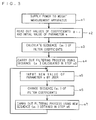
- step s1 power is supplied to the weight measurement apparatus in a step s1.
- the filter coefficient calculator 6 reads out the values of the coefficients g i,j from the coefficient storage part 8, and further reads out an initial value of the parameter x which is previously stored therewithin.
- the filter coefficient calculator 6 substitutes the values of the coefficients g i,j and the initial value of the parameter x into the equation (2), to calculate one sequence ⁇ a i ⁇ of the filter coefficients and output it to the signal processor 5, in a step s3.
- a band position of an attenuation band in filtering characteristics exhibited in the signal processor 5 is set to an initial position specified by the parameter x.
- the filter coefficients a i can be calculated promptly because the equation (2) for calculating the filter coefficients a i are expressed by a polynomial.
- the signal processor 5 carries out a filtering process on the weighing signal Ds using the one sequence ⁇ a i ⁇ of the filter coefficients which has been calculated in the step s3. Further, the signal processor 5 outputs a result of the filtering process to the microcomputer, as the signal Xs, and the microcomputer displays the weight of the object on the display part such as a CRT.
- the data entry part 7 outputs the received new value to the filter coefficient calculator 6 in a step s5.
- a user of the weight measurement apparatus inputs a value of the parameter x specifying a position of a band including a new natural frequency after the change, in order to surely eliminate the natural frequency noise, in the step s5.
- information about the natural frequency of the weight sensor 1 for each type of object under measurement is previously prepared, and the user inputs a value of the parameter x to the data entry part 7 while referring to the information, each time the type of the object is changed.
- the structure described above is configured so as to require input of a value of the parameter x to the data entry part 7, the structure may alternatively be configured so as to allow a value of the parameter x to be automatically determined.
- a weight measurement apparatus such as a weight checker in which a frequency which must be attenuated can be determined by determining a speed of a conveyor.
- automatic determination of a value of the parameter x can be accomplished by carrying out frequency analysis by means of the FFT of a vibration waveform of the measurement signal or the like and then detecting a portion of the waveform which has the greatest amplitude.
- the structure may be configured so as to implement this procedure.
- the filter coefficient calculator 6 substitutes the new value of the parameter x which is received from the data entry part 7 into the equation (2), and changes the one sequence ⁇ a i ⁇ of the filter coefficients to output a new sequence ⁇ a i ⁇ to the signal processor 5, in a step s6.
- the attenuation band in the filtering characteristics exhibited in the signal processor 5 is moved from the initial band position to a band position specified by the new value of the parameter x.
- the signal processor 5 carries out a filtering process using the new sequence ⁇ a i ⁇ of the filter coefficients obtained in the step s6, and outputs a result of the filtering process as the signal Xs.
- the user inputs a further new value of the parameter x to the data entry part 7. Then, the steps s6 and s7 are performed, so that the attenuation band is moved to a band position newly specified by the further new value of the parameter x.
- the filter coefficients a i can be changed by using the parameter x specifying a band position of an attenuation band which is physical and thus easy to grasp. Accordingly, even when a frequency which must be attenuated in the signal processor 5 is changed due to change in the natural frequency of the weight sensor 1 or the like, it is possible to easily move the attenuation band by referring to information about a new frequency which must be attenuated. Therefore, a frequency of a noise in the weighing signal Ds, which is liable to be changed, can be filtered out easily and appropriately.
- the filter coefficients a i are obtained by a predetermined arithmetic expression. This eliminates a need of preparing multistage filters which are required in the method of JP 6-21814 described in the Background section, and a need of previously storing filter coefficients representing different characteristics. Therefore, a scale of a circuit necessary for a filtering process can be reduced, which makes it possible to provide a low cost weight measurement apparatus to users.
- ⁇ p represents a normalized angular frequency of an edge of a passband
- ⁇ s represents a normalized angular frequency of an edge of a stopband
- w represents a width of an attenuation band
- ⁇ represents a parameter controlling a band position of an attenuation band.
- an attenuation band in the reference amplitude characteristics extends over an angular frequency range (which will be hereinafter simply referred to as a "frequency range”) from ⁇ to ( ⁇ + w), and a band position of the attenuation band is specified depending on a value of the parameter ⁇ , as shown in the above equation (4).
- the band position of the attenuation band in the reference amplitude characteristics will hereinafter be referred to as a "reference band position" throughout the present specification.
- a larger value of "k” indicates a large value ⁇ k .
- the optimum filter is designed through successive projections method. Detailed description thereof will be made below.
- M( ⁇ ) represents the reference amplitude characteristics M (e j ⁇ , ⁇ ). It is noted that a superscript "n" of the filter coefficients a i,k represents not an exponent, but the number of repetitions.
- a tolerance relative to the attenuation band in the reference amplitude characteristics which is employed in designing the optimal filter is set to one-tenth of a tolerance relative to the other bands in the reference amplitude characteristics, depending on the weight function.
- the filter coefficients are repeatedly updated using the above equation (10) until they converge, in other words, until e M ⁇ ⁇ ( ⁇ M ), to thereby obtain optimum filter coefficients a i , k .
- K sequences ⁇ a i,0 ⁇ , ⁇ a i,1 ⁇ , ..., ⁇ a i,K ⁇ of the filter coefficients a i,k are obtained based on respective reference amplitude characteristics which are obtained when ⁇ 0 , ⁇ 1 , ... ⁇ k are substituted for the parameter ⁇ , as well as respective values of the weight function which are obtained when ⁇ 0 , ⁇ 1 , ... ⁇ k are substituted for the parameter ⁇ .
- a matrix X for the equation (12) is obtained based on the values ⁇ k , and a vector A 0, k is obtained based on the reference filter coefficients a i, k ' which have been previously obtained through successive projections method. Accordingly, both "(X T X)" on the left side and “(X T A 0,k )” on the right side of the equation (13) can be obtained, so that the vector B 0 can be obtained.
- values obtained in the foregoing manner are employed as values of the coefficients g i,j in the equation (2), to thereby allow the parameter x to specify a band position of an attenuation band.
- a value of the parameter x that a user can input should be within a range from ⁇ 0 to ⁇ K , inclusive ( ⁇ 0 ⁇ x ⁇ ⁇ K ).
- a band position provided by a frequency range from ⁇ 0 to ( ⁇ 0 + w) is specified as a band position of the attenuation band.
- a band position provided by a frequency range from ⁇ K to ( ⁇ K + w) is specified as a band position of the attenuation band.
- the weight function W(e j ⁇ , ⁇ ) determines a weight of a tolerance used in designing the optimum filter for each frequency range, as described above. Accordingly, attenuation in the attenuation band in the filtering characteristics exhibited in the signal processor 5 is specified depending on a value of the weight function (e j ⁇ , ⁇ ) provided when a relationship ⁇
- ⁇ 0 0.3 ⁇
- ⁇ 1 is 0.31 ⁇
- ⁇ 2 is 0.32 ⁇
- a range of a value which can be substituted for the parameter x is 0.3 ⁇ ⁇ X ⁇ 0.4 ⁇ .
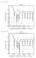
- Figs. 4 through 8 are graphs showing amplitude characteristics of an optimum filter having the reference filter coefficients a i,k ' obtained under the above-noted conditions.
- Figs. 4 through 8 show the amplitude characteristics which are observed in situations where ⁇ is ⁇ 0 , ⁇ 2 , ⁇ 5 , ⁇ 8 , and ⁇ 10 , respectively.
- the reference amplitude characteristics is assumed with respect to each of the situations shown in Figs. 4 through 8, respectively, and a solid line 10 in each of the graphs denotes a reference band position (within a frequency range from ⁇ to ( ⁇ +w)) of each reference amplitude characteristics.
- a band position of the attenuation band 9 in the optimum filter is changed in accordance with a value of the parameter ⁇ , and that an equal ripple property is found in bands other than the attenuation band 9 in the stopband.
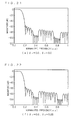
- Figs. 10 through 13 are graphs showing amplitude characteristics of a filtering process which is carried out by the signal processor 5 while the values shown in Fig. 9 are employed as values of the coefficients g i, j in the equation (2).
- Fig. 10 shows characteristics exhibited when the values ⁇ 0 , ⁇ 1 , ... and ⁇ 10 are substituted for the parameter x.
- Figs. 11, 12 and 13 show characteristics exhibited when 0.305 ⁇ , 0.355 ⁇ and 0.395 ⁇ are substituted for the parameter x, respectively.
- the reference amplitude characteristics is assumed with respect to each of situations shown in Figs. 11, 12 and 13, respectively, and the solid line 10 in each of Figs. 11, 12 and 13 denotes a reference band position (within a frequency range from ⁇ to ( ⁇ + w)) of each reference amplitude characteristics in the same manner as in Figs. 4 through 8.
- Attenuation becomes great locally in a band position specified by the parameter x. Further, it is appreciated from Figs. 10 through 13 that attenuation in the attenuation band 9 is about ten times (20 dB) greater than that in bands other than the attenuation band in the stopband.
- Fig. 14 shows a maximum error in the amplitude characteristics of the optimum filter having the reference filter coefficients a i, k ' obtained under the above-noted conditions and a maximum error in the amplitude characteristics of the filter used in the signal processor 5.
- the filter used in the signal processor 5 corresponds to a filter having the filter coefficients a i which are approximated by an Mth order polynomial b i (x) including the coefficients g i, j having the values shown in Fig. 9. It is noted that frequency ranges AR1 through AR4 in Fig.
- the respective maximum errors of the optimum filter and the filter used in the signal processor 5 have the substantially same value as a result of approximating the filter coefficients by a fifth order polynomial based on one sequence ⁇ a i , k ' ⁇ of the reference filter coefficients.
- the filter coefficients a i can be changed by using the parameter x specifying a band position of an attenuation band which is physical and thus easy to grasp. Accordingly, it is possible to easily change a band position of the attenuation band. Therefore, a frequency of a noise in the weighing signal Ds, which is liable to be changed, can be filtered out easily and appropriately.
- an attenuation band with a width extending along an axis of frequency is moved by using the parameter x.
- the number of the values ⁇ k is set to three or more.
- the sequences ⁇ a i, k ' ⁇ of the reference filter coefficients which have been calculated in that way is used in determining values of the coefficients g i,j in the equation (2).
- the present invention can also be applied to a general method of designing a digital filter.
- a brief description about a method of designing a digital filter in which a position of an attenuation band is variable will be made.
- a plurality of sequences ⁇ a i, k ' ⁇ of reference filter coefficients are calculated from reference amplitude characteristics in the same manner as described above.
- values of the coefficients g i,j are determined using the calculated sequences ⁇ a i,k ' ⁇ , and the filter coefficients a i,k of the digital filter are approximated by the equation (2).
- a value is substituted for the parameter x in the equation (2), to obtain one sequence ⁇ a i ⁇ of the filter coefficients of the digital filter.
- the value of the parameter x is changed to thereby change the filter coefficients.
- the attenuation band is moved to a new band position newly specified by the parameter x.
- reference amplitude characteristics are expressed by the following equation (21) in a corresponding relationship to the equation (4):
- M e j ⁇ ⁇ ⁇ ⁇ 1 0 ⁇ ⁇ ⁇ ⁇ p 0 ⁇ s ⁇ ⁇ ⁇ ⁇ 1 0 ⁇ 1 ⁇
- a weight function is expressed by the following equation (22) in a corresponding relationship to the equation (5):
- W e j ⁇ ⁇ ⁇ ⁇ 1 0 ⁇ ⁇ ⁇ ⁇ p 0 ⁇ s ⁇ ⁇ ⁇ ⁇ 1 10 ⁇ 1 ⁇
- ⁇ 1 " and ⁇ 2 " represent spectrum parameters controlling band positions of the respective attenuation bands, and are given as the lowest limit values of normalized angular frequencies of the respective attenuation bands.
- the preferred embodiment according to the present invention is intended for the design of a filter in which desired attenuation can be obtained in each of a plurality of attenuation bands by approximating ⁇ 1 and ⁇ 2 equally in the course of design.
- ⁇ p represents a normalized angular frequency of an edge of a passband
- ⁇ s represents a normalized angular frequency of an edge of a stopband
- ⁇ 1 , ⁇ 2 , ... ⁇ K represent a center normalized angular frequency of each band where great stopband attenuation is required
- ⁇ 1 , ⁇ 2 , ... ⁇ K represent a band width of each band where great stopband attenuation is required.
- ⁇ K represent a spectrum parameter, and is expressed by the following equation (26): ⁇ 1 ⁇ ⁇ 1 ⁇ min ⁇ ⁇ 1 ⁇ max ⁇ 2 ⁇ ⁇ 2 ⁇ min ⁇ ⁇ 2 ⁇ max ⁇ ⁇ k ⁇ ⁇ kmin ⁇ ⁇ kmax
- each band is specified by a spectrum parameter not as the lowest limit value of a frequency as in the above-described conventional art, but as the amount of deviation from its center frequency (the amount of displacement from a center frequency in a range where each attenuation band should vary).
- the preferred embodiment is the same as the above-described conventional art. Detailed descriptions of the apparatus configuration and the like are thus omitted.
- h (i, ⁇ 1 , ⁇ 2 , ... ⁇ K ) changes as the spectrum parameter changes.
- coefficients are approximated using an L i -th order polynomial for each spectrum parameter.
- the "j" changes consecutively from 0 to (N+1) (L 1 +1) (L 2 +1) as indicated below, with its corresponding l 1, j , l 2, j changing as indicated below:
- I 2 [ 0 , ⁇ , L 2 ⁇ L 2 + 1 , 0 , ⁇ , I 2 , j , ⁇
- ⁇ C ⁇ represents a maximum integral value that does not exceed "c"
- mod (a, b) represents the remainder obtained when "a" is divided by "b”.
- a passband is separated into 20 equal parts and the entire stopband is separated into 500 equal parts in this example. Also, the amounts of variation in angular frequency of great attenuation are separated at 0.05 intervals respectively.
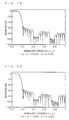
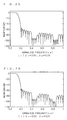
- the result amplitude characteristics are shown in Figs. 17 through 26. These figures show that the amplitude characteristics vary as the spectrum parameters ⁇ 1 and ⁇ 2 vary, respectively, to be approximated to desired amplitude characteristics.
- Fig. 26 shows that good amplitude characteristics with an error of 0.0034 (-49dB) in an area of small attenuation and an error of 0.000013 (-97dB) in an area of great attenuation are obtained even for an unseparated point. It is understood from the above that the filter according to the present embodiment can successively move a plurality of stopbands.
- an FIR filter was designed that has fixed coefficients with an unmoved stopband where the amount of great stopband attenuation is not less than at least -90dB, assuming that from 0.2 ⁇ to 0.3 ⁇ is a weight "1", and from 0.3 ⁇ to 0.9 ⁇ is a weight "10".
- the result amplitude characteristics are shown in Fig. 16.
- This filter is of an 80th order which requires more orders than a 60th order filter in which a stopband is variable, so the amount of delay thereof is greater than that of a filter in which a stopband is variable. Therefore, designing a filter in which a plurality of stopbands are locally variable like the filter according to the present embodiment is effective in reducing a filter order as in the conventional art, and is effective for high-speed and high-accuracy measurement.
- the present invention is also applicable to the design of a filter in which one stopband is variable.
- the design of a low pass filter has been discussed above, the present invention is also applicable to the design of other filters than a low pass filter (such as a band path filter and a high pass filter).
- the design of an FIR filter has been described, the present invention is also applicable to the design of an IIR filter.
Landscapes
- Physics & Mathematics (AREA)
- Engineering & Computer Science (AREA)
- Computer Hardware Design (AREA)
- Mathematical Physics (AREA)
- General Physics & Mathematics (AREA)
- Indication And Recording Devices For Special Purposes And Tariff Metering Devices (AREA)
- Measurement Of Mechanical Vibrations Or Ultrasonic Waves (AREA)
Abstract
Description
- The present invention relates to a filtering technique carried out by using a digital filter.
- A weight measurement apparatus for measuring a weight of an article typically employs a weight sensor such as a strain gauge load cell or a force balance. The weight sensor has a natural frequency which is subject to a total weight of a weight of an article and a tare thereof. When external vibration at frequencies in a band including the natural frequency acts upon a weight measurement system, external vibration at a frequency close to the natural frequency is amplified, to work as a vibration noise, which then emerges in a weighing signal output from the weight sensor. It is noted that such a vibration noise will be hereinafter referred to as a "natural frequency noise" throughout the present specification.
- Also, in measuring a load of a transfer system, a noise caused due to vibration of a rotation system such as a motor for driving a conveyor belt or a transfer roller, or an electrical noise associated with a commercial power supply, works as a vibration noise which is superimposed on a weighing signal.
- A weight measurement apparatus developed in recent days has employed a digital filter for eliminating such a vibration noise as described above which is contained in a weighing signal. A digital filter is relatively impervious to influence of aging or an environment, and filtering characteristics thereof can be relatively easily altered. Among various types of digital filters, a finite impulse response (FIR) filter has been preferably employed in view of its excellent stability.
- As described above, a natural frequency of a weight sensor is subject to an article weight and a tare. Thus, if an article weight or a tare is changed, it results in change in a frequency of a natural frequency noise associated with the weight sensor. Formerly, change in frequency of a natural frequency noise caused due to change in article weight was negligible because a tare, e.g., a weight of a conveyor, was dominant. However, in recent days, there has been arisen a demand for accurate measurement of a weight of a light article, which involves reduction of a tare. For this reason, such change in frequency of a natural frequency noise caused due to change in article weight has become too significant to neglect. On the other hand, a frequency of a vibration noise associated with a motor or a transfer roller is changed in accordance with specifications of a transfer system such as a transfer speed, for example. Hence, it is desired to achieve a digital filter which is capable of surely eliminating a vibration noise in spite of change in frequency of the vibration noise which occurs due to change in type or size of an article under measurement, or change in specifications of a transfer system.
- In accordance with the conventional practices, a digital filter formed of multistage moving average filters is employed in order to surely eliminate a vibration noise contained in a weighing signal, as taught in
Japanese Patent Publication No. 6-21814 JP 6-21814 - More specifically,
JP 6-21814 - Additionally, an example of a method of designing an FIR filter is described in "Design of FIR Transmitter and Receiver Filters for Data Communication System" by Naoyuki Aikawa et al. in Transaction of IEICE, Vol. J79-A, No. 3, March 1996, pages 608-615, which shows a technique using successive projections method.
- According to the method shown in
JP 6-21814 - In this regard, to initially design a digital filter which allows for addition of a specification in a weight measurement apparatus requires preparing numerous multistage moving average filters, which results in increase of a circuit scale of the digital filter.
- On the other hand, as an alternative to the method taught in
JP 6-21814 - It is an object of the present invention to provide a filtering technique which makes it possible to easily and appropriately eliminate a noise without increasing a scale of a circuit necessary for a filtering process even if a noise frequency is liable to be changed.
- In an aspect of the present invention, a noise eliminating apparatus includes: a signal processor for carrying out a filtering process on a digital signal by using variable filter coefficients; and a filter coefficient calculator for calculating the filter coefficients using a predetermined arithmetic expression and outputting the filter coefficients to the signal processor. The arithmetic expression includes parameters specifying respective band positions of a plurality of attenuation bands where attenuation is to be enhanced locally in a stopband of amplitude characteristics of the filtering process, and the filter coefficient calculator substitutes input values of the parameters into the arithmetic expression, to change the filter coefficients so that the plurality of attenuation bands are independently movable to respective desired band positions specified by the parameters.
- The present invention is also intended for a method of eliminating a noise.
- The filter coefficients can be changed by using the parameter specifying the band position of the attenuation band which is physical and thus easy to grasp. As such, even when a frequency which must be attenuated is changed, it is possible to easily move the attenuation band by referring to information about a new frequency which must be attenuated. Accordingly, a frequency of a noise, which is liable to be changed, can be filtered out easily and appropriately. Further, since the filter coefficients are obtained by the arithmetic expression, there is no need of preparing multistage filters or previously storing filter coefficients representing different characteristics. This makes it possible to reduce a scale of a circuit necessary for the filtering process and to thus provide a low cost noise eliminating apparatus to users. Moreover, since a plurality of attenuation bands can be specified, a plurality of causes causing a big noise and varying can be dealt with appropriately.
- In another aspect of the present invention, a weight measurement apparatus includes: a measurer for detecting a weight of an object; and the noise eliminating apparatus mentioned above for carrying out a filtering process on a digital signal which is obtained as a measurement result by the measurer.
- A weight measurement apparatus capable of filtering a noise appropriately can be obtained.
- The present invention is also intended for a method of designing a digital filter in which respective band positions of a plurality of attenuation bands where attenuation is to be enhanced locally in a stopband of amplitude characteristics are variable. This method includes the steps of: (a) calculating a plurality of sequences of reference filter coefficients based on reference amplitude characteristics of the digital filter; (b) approximating filter coefficients of the digital filter using a predetermined arithmetic expression including parameters specifying the respective band positions of the plurality of attenuation bands, based on the plurality of sequences of the reference filter coefficients; and (c) calculating the filter coefficients using the predetermined arithmetic expression. The step (c) includes the step of (c-1) substituting values of the parameters into the predetermined arithmetic expression, to change the filter coefficients, and the plurality of attenuation bands are independently moved to respective desired band positions specified by the parameters by performing the step (c-1).
- The filter coefficients can be changed by using the parameter specifying the band position of the attenuation band which is physical and thus easy to grasp. As such, even when a frequency which must be attenuated is changed, it is possible to easily move the attenuation band by referring to information about a new frequency which must be attenuated. Accordingly, a frequency of a noise, which is liable to be changed, can be filtered out easily and appropriately. Further, since the filter coefficients are obtained by the arithmetic expression, there is no need of preparing multistage filters. This makes it possible to reduce a scale of a circuit of the digital filter. Moreover, since a plurality of attenuation bands can be specified, a plurality of causes causing a big noise and varying can be dealt with appropriately.
- Preferably, each of the parameters is given as the amount of displacement from a center frequency in a range where a corresponding attenuation band among the plurality of attenuation bands is to vary.
- A plurality of parameters can be approximated equally in designing a filter, which in turn allows the design of a desired filter.
- These and other objects, features, aspects and advantages of the present invention will become more apparent from the following detailed description of the present invention when taken in conjunction with the accompanying drawings.
-
- Fig. 1 is a block diagram illustrating a structure of a weight measurement apparatus according to conventional art of the present invention.
- Fig. 2 is a graph showing amplitude characteristics of a filtering process in a signal processor according to the conventional art of the present invention.
- Fig. 3 is a flow chart illustrating operations for measuring a weight in the weight measurement apparatus according to the conventional art of the present invention.
- Figs. 4 through 8 are graphs showing amplitude characteristics of an optimum filter.
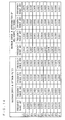
- Fig. 9 shows values of coefficients gi,j.
- Figs. 10 through 13 are graphs showing amplitude characteristics of the filtering process in the signal processor according to the conventional art of the present invention.
- Fig. 14 shows respective maximum errors of the optimum filter and a filter used in the signal processor according to the conventional art of the present invention.
- Fig. 15 shows a method of defining spectrum parameters according to a preferred embodiment of the present invention.
- Fig. 16 shows amplitude characteristics when an FIR filter with fixed coefficients is designed.
- Figs. 17 through 26 show variations in amplitude characteristics when spectrum parameters δ 1 and δ 2 are varied.
- Before describing a preferred embodiment according to the present invention, a weight measurement apparatus serving as conventional art of the present invention will be described. The conventional art is disclosed in
Japanese Patent Application Laid-Open No. 2004-150883 - Fig. 1 is a block diagram illustrating the structure of the weight measurement apparatus according to the conventional art. As illustrated in Fig. 1, the weight measurement apparatus according to the conventional art includes a
weight sensor 1 such as a strain gauge load cell or a force balance, anamplifier 2, ananalog filter 3, an A/D converter (which will be hereinafter referred to as an "ADC") 4, asignal processor 5, afilter coefficient calculator 6, adata entry part 7 and acoefficient storage part 8. - The
weight sensor 1 detects a weight of an object under measurement, which is notified by a weight measurement system, and outputs a result of the detection to theamplifier 2, as a measurement signal ms. Theamplifier 2 amplifies the measurement signal ms input by theweight sensor 1, and outputs it to theanalog filter 3, as an amplified signal MS. Theanalog filter 3 removes an unnecessary higher frequency component from the amplified signal MS, to output a resultant signal as an analog signal As. TheADC 4 samples the analog signal As output from theanalog filter 3 at predetermined sampling intervals, to generate a digital signal which is quantized to be represented by the predetermined number of bits and then output the digital signal to thesignal processor 5, as a weighing signal Ds. - The
signal processor 5 carries out a filtering process on the weighing signal Ds input by theADC 4, using a FIR filter, and outputs a result of the filtering process to a microcomputer (not illustrated), as a signal Xs. Then, the microcomputer calculates the weight of the object based on the signal Xs and displays a result of the calculation on a display part (not illustrated). It is noted that generally, a frequency response H (ejω) of a 2Nth order FIR filter is expressed by the following equation (1):
- In the equation (1), "ai" (i =0, 1, 2, ..., N) represents filter coefficients. Also, "ω" represents a normalized angular frequency, that is, an angular frequency normalized by using a sampling frequency used for a filtering process on data. In the conventional art, an angular frequency which is normalized by using a sampling frequency used for the filtering process on data carried out by the
signal processor 5 corresponds to the normalized angular frequency represented by "ω". It is noted that the terms "normalized angular frequency" will hereinafter mean such an angular frequency as defined above, i.e., an angular frequency which is normalized by using a sampling frequency, throughout the present specification. - Fig. 2 is a graph showing an example of amplitude characteristics of the filtering process carried out by the
signal processor 5. As shown in Fig. 2, the FIR filter used in thesignal processor 5 is a low pass filter, so that anattenuation band 9 where attenuation is locally great is present in a stopband of the amplitude characteristics. The weight measurement apparatus according to the conventional art can function to change a band position of theattenuation band 9. More specifically, the weight measurement apparatus can function to move theattenuation band 9 to a higher frequency position or a lower frequency position. It is noted that the terms "attenuation band" will hereinafter mean a band where attenuation must be enhanced locally in a stopband, like theattenuation band 9 shown in Fig. 2, throughout the present specification. - The
filter coefficient calculator 6 calculates sequences {ai} of the filter coefficients ai in the above equation (1) using the following equation (2), and outputs a result of the calculation to the signal processor 5:
- In the equation (2), "gi,j" (j=0, 1, 2, ... M) represents coefficients. Also, "x" represents a parameter specifying a band position of an attenuation band, and a value substituted for x is varied in accordance with the position of the attenuation band. As shown in the equation (2), the filter coefficients a; are expressed by a polynomial including a plurality of terms for the parameter x. Then, by substituting the equation (2) into the equation (1), the frequency response H (ejω) can be expressed by the following equation (3):

- The
coefficient storage part 8 is a ROM (Read-Only Memory), for example, and previously stores values of the coefficients gi,j. The values of the coefficients gi,j are read out from thecoefficient storage part 8 by thefilter coefficient calculator 6. - The
data entry part 7 is a keyboard, for example, and receives a value of the parameter x which is input by a user external to the weight measurement apparatus. Thedata entry part 7 then outputs the received value of the parameter x to thefilter coefficient calculator 6. - Next, operations for measuring a weight of an object in the weight measurement apparatus according to the conventional art will be described with reference to a flow chart in Fig. 3.
- As illustrated in Fig. 3, power is supplied to the weight measurement apparatus in a step s1. In a subsequent step s2, the
filter coefficient calculator 6 reads out the values of the coefficients gi,j from thecoefficient storage part 8, and further reads out an initial value of the parameter x which is previously stored therewithin. - Then, the
filter coefficient calculator 6 substitutes the values of the coefficients gi,j and the initial value of the parameter x into the equation (2), to calculate one sequence {ai} of the filter coefficients and output it to thesignal processor 5, in a step s3. As a result, a band position of an attenuation band in filtering characteristics exhibited in thesignal processor 5 is set to an initial position specified by the parameter x. It is noted that the filter coefficients ai can be calculated promptly because the equation (2) for calculating the filter coefficients ai are expressed by a polynomial. - Thereafter, in a step s4, the
signal processor 5 carries out a filtering process on the weighing signal Ds using the one sequence {ai} of the filter coefficients which has been calculated in the step s3. Further, thesignal processor 5 outputs a result of the filtering process to the microcomputer, as the signal Xs, and the microcomputer displays the weight of the object on the display part such as a CRT. - Then, upon receipt of a new value of the parameter x input by a user of the weight measurement apparatus, the
data entry part 7 outputs the received new value to thefilter coefficient calculator 6 in a step s5. - As described above, change in type of an object or the like results in change in a natural frequency of the
weight sensor 1 and thus change in frequency of a natural frequency noise contained in the weighing signal Ds. In this connection, a user of the weight measurement apparatus inputs a value of the parameter x specifying a position of a band including a new natural frequency after the change, in order to surely eliminate the natural frequency noise, in the step s5. For example, information about the natural frequency of theweight sensor 1 for each type of object under measurement is previously prepared, and the user inputs a value of the parameter x to thedata entry part 7 while referring to the information, each time the type of the object is changed. - It is noted that though the structure described above is configured so as to require input of a value of the parameter x to the
data entry part 7, the structure may alternatively be configured so as to allow a value of the parameter x to be automatically determined. For example, this alternative is possible in a weight measurement apparatus such as a weight checker in which a frequency which must be attenuated can be determined by determining a speed of a conveyor. Further alternatively, automatic determination of a value of the parameter x can be accomplished by carrying out frequency analysis by means of the FFT of a vibration waveform of the measurement signal or the like and then detecting a portion of the waveform which has the greatest amplitude. The structure may be configured so as to implement this procedure. - Turning back to the flow chart, subsequently to the step s5, the
filter coefficient calculator 6 substitutes the new value of the parameter x which is received from thedata entry part 7 into the equation (2), and changes the one sequence {ai} of the filter coefficients to output a new sequence {ai} to thesignal processor 5, in a step s6. As a result, the attenuation band in the filtering characteristics exhibited in thesignal processor 5 is moved from the initial band position to a band position specified by the new value of the parameter x. Then, in a step s7, thesignal processor 5 carries out a filtering process using the new sequence {ai} of the filter coefficients obtained in the step s6, and outputs a result of the filtering process as the signal Xs. - If there is a need of changing again the position of the attenuation band, the user inputs a further new value of the parameter x to the
data entry part 7. Then, the steps s6 and s7 are performed, so that the attenuation band is moved to a band position newly specified by the further new value of the parameter x. - As is made clear from the foregoing description, in the weight measurement apparatus according to the conventional art, the filter coefficients ai can be changed by using the parameter x specifying a band position of an attenuation band which is physical and thus easy to grasp. Accordingly, even when a frequency which must be attenuated in the
signal processor 5 is changed due to change in the natural frequency of theweight sensor 1 or the like, it is possible to easily move the attenuation band by referring to information about a new frequency which must be attenuated. Therefore, a frequency of a noise in the weighing signal Ds, which is liable to be changed, can be filtered out easily and appropriately. - Moreover, as shown in the equation (2), the filter coefficients ai are obtained by a predetermined arithmetic expression. This eliminates a need of preparing multistage filters which are required in the method of
JP 6-21814 - Next, processes for determining values of the coefficients gi,j will be described. First, ideal amplitude characteristics M (ejω, φ), in other words, reference amplitude characteristics, and a weight function W (ejω, φ) of a FIR filter in which a band position of an attenuation band is variable are provided by the following equations (4) and (5):


- In the equations (4) and (5), "ωp" represents a normalized angular frequency of an edge of a passband, "ωs" represents a normalized angular frequency of an edge of a stopband, "w" represents a width of an attenuation band, and "φ" represents a parameter controlling a band position of an attenuation band. Among those, a relationship ωs < φ < π - w is maintained.
- According to the conventional art, an attenuation band in the reference amplitude characteristics extends over an angular frequency range (which will be hereinafter simply referred to as a "frequency range") from φ to (φ + w), and a band position of the attenuation band is specified depending on a value of the parameter φ, as shown in the above equation (4). The band position of the attenuation band in the reference amplitude characteristics will hereinafter be referred to as a "reference band position" throughout the present specification.
- Subsequently, an optimum filter is designed for each of values φ k (k = 0, 1, 2, ... K) which is to be substituted for the parameter φ. A larger value of "k" indicates a large value φ k. In the conventional art, the optimum filter is designed through successive projections method. Detailed description thereof will be made below.
- Given that the filter coefficients a; provided when the values φk are substituted for the parameter φ are filter coefficients ai,k, a frequency response H(ejω, φk) of a digital filter provided when each of the values φk is substituted for the parameter φ is expressed by the following equation (6):

- Then, in order to obtain the filter coefficients ai,k through successive projections method, an error e( ω) found in an n-time calculation of repeated calculations is expressed by the following equation (7):

- In the equation (7), "M( ω)" represents the reference amplitude characteristics M (ejω, φ). It is noted that a superscript "n" of the filter coefficients ai,k represents not an exponent, but the number of repetitions.
- Now, given that a frequency at which specifications are most slightly met is "ω M" and a tolerance relative to the reference amplitude characteristics is "λ(ω)", the following equation (8) is established:

- Given that a tolerance obtained when the weight function W(ejω, φ) is equal to 1 is "δ", the tolerance λ (ω) is expressed by the following equation (9):

- In the equation (9), "W( ω)" represents the weight function "W(ejω, φ)".
- As shown in the equations (5) and (9), a tolerance relative to the attenuation band in the reference amplitude characteristics which is employed in designing the optimal filter is set to one-tenth of a tolerance relative to the other bands in the reference amplitude characteristics, depending on the weight function.
- The filter coefficients are updated in successive projections method by using the following equation (10):
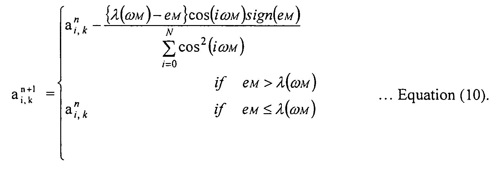
- In the equation (10), "eM" is equal to "e(ωM)".
- The filter coefficients are repeatedly updated using the above equation (10) until they converge, in other words, until eM ≦ λ (ωM), to thereby obtain optimum filter coefficients ai, k.
- In this manner, K sequences {ai,0}, {ai,1}, ..., {ai,K} of the filter coefficients ai,k are obtained based on respective reference amplitude characteristics which are obtained when φ0, φ 1, ... φk are substituted for the parameter φ, as well as respective values of the weight function which are obtained when φ0, φ1, ... φk are substituted for the parameter φ. The optimum filter coefficients ai, k obtained based on the reference amplitude characteristics and the weight function will serve as reference filter coefficients ai,k' (k = 0, 1, 2, ... K).
- Next, least square approximation is carried out on the reference filter coefficients ai, k' using an Mth order polynomial bi(x) in the equation (2), to determine values of the coefficients gi,j.
- To this end, a value b0( φ k) obtained when any of the values φ k is substituted for the parameter x and the filter coefficients a0, k' are dealt with, first. The following equation (11) is provided:

- In order to carry out least square approximation on the reference filter coefficients ai, k' using a polynomial bi(x), to calculate a vector B0 =[g0, 0 g0, 1 ... g0, M]T which allows "S" in the above equation (11) to be minimized is statistically preferable, as is well known. A specific procedure for the calculation is to solve simultaneous equations given by the following equation (12) which shows conditions for obtaining maximum and minimum values, for "g0,0, g0, 1, ..., g0, M":

- Then, expression of the equation (12) using normal equations is as follows:


- A matrix X for the equation (12) is obtained based on the values φk, and a vector A0, k is obtained based on the reference filter coefficients ai, k' which have been previously obtained through successive projections method. Accordingly, both "(XTX)" on the left side and "(XTA0,k)" on the right side of the equation (13) can be obtained, so that the vector B0 can be obtained.
- A value b1(φk) and the reference filter coefficients a1, k', a value b2(φk) and the reference filter coefficients a2, k', ..., and a value bN(φk) and the reference filter coefficients aN, k' are dealt with by following the same procedures as described above, to obtain a vector Bi = [gi,0gi,1 ... gi,M]T.
- According to the conventional art, values obtained in the foregoing manner are employed as values of the coefficients gi,j in the equation (2), to thereby allow the parameter x to specify a band position of an attenuation band.
- Also, in the conventional art, when the reference amplitude characteristics is defined as expressed by the equation (4), a value of the parameter x that a user can input should be within a range from φ 0 to φ K, inclusive (φ 0 ≦ x ≦ φ K). For example, if the user inputs the value φ 0 as a value of the parameter x to the
data entry part 7, a band position provided by a frequency range from φ 0 to (φ 0 + w) is specified as a band position of the attenuation band. If the user inputs the value φ K as a value of the parameter x to thedata entry part 7, a band position provided by a frequency range from φK to (φK + w) is specified as a band position of the attenuation band. - As described above, the user can specify a band position of an attenuation band within a frequency range from a reference band position in the reference amplitude characteristics provided when φ = φ0 to another reference band position in the reference amplitude characteristics provided when φ = φ K, by means of the parameter x. Also, by previously preparing a table establishing a correspondence between a value of the parameter x and a band position of an attenuation band, the user can easily specify a desired band position.
- Additionally, the weight function W(ejω, φ) determines a weight of a tolerance used in designing the optimum filter for each frequency range, as described above. Accordingly, attenuation in the attenuation band in the filtering characteristics exhibited in the
signal processor 5 is specified depending on a value of the weight function (ejω, φ) provided when a relationship φ≦|ω|≦φ+w is maintained. In the conventional art, attenuation in the attenuation band which is provided by thesignal processor 5 is set to ten times of attenuation in the other bands in the stopband, as shown in the equation (5). - Next, specific description will be made about how a band position of an attenuation band is changed on an axis of frequency depending on a value of the parameter x, by substituting specific numerical values for the coefficients gi,j.
- First, conditions are laid down as follows, for example.


- Also, assume that φ is in a range from 0.3 π to 0.4 π, inclusive (0.3 π ≦ φ ≦ 0.4 π) and that discrete values obtained by dividing the range into 11 equal parts correspond to the values φ k(k = 0,1, ..., 10). Then, φ 0 is 0.3 π (φ0 = 0.3 π ), φ 1 is 0.31 π (φ 1 = 0.31 π), φ 2 is 0.32 π (φ2 = 0.32 π), ..., and φ 10 is 0.4 π (φ10 = 0.4 π). Accordingly, a range of a value which can be substituted for the parameter x is 0.3 π ≦X≦0.4 π.
- Figs. 4 through 8 are graphs showing amplitude characteristics of an optimum filter having the reference filter coefficients ai,k' obtained under the above-noted conditions. Figs. 4 through 8 show the amplitude characteristics which are observed in situations where φ is φ0, φ2, φ5, φ8, and φ10, respectively. The reference amplitude characteristics is assumed with respect to each of the situations shown in Figs. 4 through 8, respectively, and a
solid line 10 in each of the graphs denotes a reference band position (within a frequency range from φ to (φ +w)) of each reference amplitude characteristics. - Referring to Figs. 4 through 8, it is appreciated that a band position of the
attenuation band 9 in the optimum filter is changed in accordance with a value of the parameter φ, and that an equal ripple property is found in bands other than theattenuation band 9 in the stopband. - Next, the reference filter coefficients ai, k' obtained under the above-noted conditions are approximated by a fifth order polynomial (M = 5), to determine values of the coefficients gi,j, which are shown in Fig. 9.
- Figs. 10 through 13 are graphs showing amplitude characteristics of a filtering process which is carried out by the
signal processor 5 while the values shown in Fig. 9 are employed as values of the coefficients gi, j in the equation (2). Specifically, Fig. 10 shows characteristics exhibited when the values φ 0, φ 1, ... and φ 10 are substituted for the parameter x. Figs. 11, 12 and 13 show characteristics exhibited when 0.305 π, 0.355 π and 0.395 π are substituted for the parameter x, respectively. The reference amplitude characteristics is assumed with respect to each of situations shown in Figs. 11, 12 and 13, respectively, and thesolid line 10 in each of Figs. 11, 12 and 13 denotes a reference band position (within a frequency range from φ to (φ + w)) of each reference amplitude characteristics in the same manner as in Figs. 4 through 8. - Referring to Fig. 11, when 0.305 π is substituted for the parameter x, attenuation becomes great in a frequency range from about 0.305 π to 0.405 π (a range denoted by the solid line 10). Also, referring to Fig. 12, when 0.355 π is substituted for the parameter x, attenuation becomes great in a frequency range from about 0.355 π to 0.455 π. Then, turning to Fig. 13, when 0.395 π is substituted for the parameter x, attenuation becomes great in a frequency range from about 0.395 π to 0.495 π.
- It is appreciated from Figs. 11, 12 and 13 that attenuation becomes great locally in a band position specified by the parameter x. Further, it is appreciated from Figs. 10 through 13 that attenuation in the
attenuation band 9 is about ten times (20 dB) greater than that in bands other than the attenuation band in the stopband. - Fig. 14 shows a maximum error in the amplitude characteristics of the optimum filter having the reference filter coefficients ai, k' obtained under the above-noted conditions and a maximum error in the amplitude characteristics of the filter used in the
signal processor 5. The filter used in thesignal processor 5 corresponds to a filter having the filter coefficients ai which are approximated by an Mth order polynomial bi(x) including the coefficients gi, j having the values shown in Fig. 9. It is noted that frequency ranges AR1 through AR4 in Fig. 14 are a frequency range of 0 ≦|ω|≦ ω p, a frequency range of ω s≦|ω|≦φk, a frequency range of φ k ≦|ω|≦φ k + w, and a frequency range of φk + w≦|ω|≦ π, respectively. - As shown in Fig. 14, the respective maximum errors of the optimum filter and the filter used in the
signal processor 5 have the substantially same value as a result of approximating the filter coefficients by a fifth order polynomial based on one sequence {ai, k'} of the reference filter coefficients. - As is made clear from the foregoing description, in the weight measurement apparatus according to the conventional art, the filter coefficients ai can be changed by using the parameter x specifying a band position of an attenuation band which is physical and thus easy to grasp. Accordingly, it is possible to easily change a band position of the attenuation band. Therefore, a frequency of a noise in the weighing signal Ds, which is liable to be changed, can be filtered out easily and appropriately.
- Additionally, the number of the values φk (k = 0, 1, ..., K) to be substituted for the parameter φ used in obtaining the coefficients gi,j is preferably three or more (K ≧ 3) for the following reasons.
- According to the conventional art, an attenuation band with a width extending along an axis of frequency is moved by using the parameter x. As such, it is desired to bring a width of the attenuation band close to an appropriate band width (the band width w in the equation (4)) not only in opposite ends of a frequency range within which the band position of the attenuation band can be specified by the parameter x (which will hereinafter be referred to as a "specified frequency range"), but also in a middle portion of the specified frequency range.
- To this end, the number of the values φk is set to three or more. This results in the sequences {ai,k'} of the reference filter coefficients being calculated based on not only reference amplitude characteristics in the opposite ends of the specified frequency range, i.e., reference amplitude characteristics exhibited when φ = φ0 and φ = φk, but also reference characteristics in the middle portion thereof. The sequences {ai, k'} of the reference filter coefficients which have been calculated in that way is used in determining values of the coefficients gi,j in the equation (2). In other words, to set the number of the values φk to three or more would allow the equation (2) for the filter coefficients to be derived from not only the reference amplitude characteristics in the opposite ends of the specified frequency range, but also the reference amplitude characteristics in the middle portion thereof. This prevents a considerable difference between the appropriate band width w and the band width of the attenuation band in the middle portion of the specified frequency range, as well as between the appropriate band width w and the band width of the attenuation band in the opposite ends of the specified frequency range.
- Moreover, though the above description in the conventional art has been made with respect to a weight measurement apparatus, the present invention can also be applied to a general method of designing a digital filter. Below, a brief description about a method of designing a digital filter in which a position of an attenuation band is variable will be made.
- First, a plurality of sequences {ai, k'} of reference filter coefficients are calculated from reference amplitude characteristics in the same manner as described above. Subsequently, values of the coefficients gi,j are determined using the calculated sequences {ai,k'}, and the filter coefficients ai,k of the digital filter are approximated by the equation (2). Then, a value is substituted for the parameter x in the equation (2), to obtain one sequence {ai} of the filter coefficients of the digital filter.
- In order to change the band position of the attenuation band in filtering characteristics, the value of the parameter x is changed to thereby change the filter coefficients. As a result, the attenuation band is moved to a new band position newly specified by the parameter x.
- By employing the foregoing method of designing a digital filter, it is possible to easily move an attenuation band. Accordingly, even if a noise frequency is liable to be changed, it is possible to eliminate a noise easily and appropriately. Further, as the filter coefficients are obtained by an arithmetic expression, there is no need for forming the digital filter with multistage filters which are required in
JP 6-21814 - In the conventional art described above, only one attenuation band is variable in a stopband, as shown in the equation (5). Yet there may be cases where a big noise is caused by a plurality of causes, and the causes vary. Accordingly, the design of a filter will be described below in which a plurality of attenuation bands can be variably set using the conventional art method.
- In this case, reference amplitude characteristics are expressed by the following equation (21) in a corresponding relationship to the equation (4):

- Also, a weight function is expressed by the following equation (22) in a corresponding relationship to the equation (5):

- In the equations (21) and (22), " φ1" and "φ2" represent spectrum parameters controlling band positions of the respective attenuation bands, and are given as the lowest limit values of normalized angular frequencies of the respective attenuation bands.
- Given that the filter coefficients in φ1 and φ2 are filter coefficients ai, j, k, the following equation (23) is established:

- Thus, a transfer function of the filter in which a plurality of bands are variable is expressed by the following equation (24):

- In the conventional art, frequency parameters of a plurality of attenuation bands themselves are used in the course of design. Accordingly, when φ1 = 0.3, φ2 = 0.8, j = 4, and k = 4, then φ1 4 = 0.34 = 0.0081, and φ2 4 = 0.84 = 0.4096 in the equation (24). As such, φ1 4 takes on a very small value compared to φ2 4, so φ1 and φ2 cannot be approximated equally in designing the filter. As a result, desired attenuation cannot be obtained in the φ1 side band.
- Therefore, the preferred embodiment according to the present invention is intended for the design of a filter in which desired attenuation can be obtained in each of a plurality of attenuation bands by approximating φ1 and φ2 equally in the course of design.
- As shown in Fig. 15, desired frequency characteristics in which K stopbands (attenuation bands) are variable are expressed by the following equation (25):

- In the equation (25), "ωp" represents a normalized angular frequency of an edge of a passband, "ωs" represents a normalized angular frequency of an edge of a stopband, "φ1, φ2, ... φK" represent a center normalized angular frequency of each band where great stopband attenuation is required, and " τ 1, τ 2, ... τ K" represent a band width of each band where great stopband attenuation is required. Also, "δ1, δ2, ... δ K" represent a spectrum parameter, and is expressed by the following equation (26):

- Additionally, a weight function is expressed by the following equation (27):

- In the equation (27), "g1, g2, ...gK" represent a weight of each band where great stopband attenuation is required, and takes on a positive real number value. As described above, the preferred embodiment according to the present invention is characterized in that each band is specified by a spectrum parameter not as the lowest limit value of a frequency as in the above-described conventional art, but as the amount of deviation from its center frequency (the amount of displacement from a center frequency in a range where each attenuation band should vary). Other than providing a spectrum parameter as the amount of deviation from a center frequency, the preferred embodiment is the same as the above-described conventional art. Detailed descriptions of the apparatus configuration and the like are thus omitted.
- A frequency response of a transfer function of a 2Nth order linear phase FIR filter in which a plurality of stopbands are variable approximating characteristics having the above-mentioned desired characteristics and weight is expressed by the following equation (28) using the spectrum parameter:

- In the equation (28), a value of h (i, δ1, δ2, ... δK) changes as the spectrum parameter changes. Thus by extending the above-described conventional art, coefficients are approximated using an Li-th order polynomial for each spectrum parameter.

- When φ1 = 0.3, φ 2 = 0.8, δ1 = 0.2, δ 2 = 0.2, 11 = 4, and 12 = 4 in the equation (29) where δ 1 and δ 2 are provided instead of φ 1 and φ 2 as parameters, δ 1 4 and δ 2 4 take on the same value of 0.0016. Accordingly, δ 1 and δ 2 can be approximated equally in designing the filter, which in turn allows the design of a desired filter.
- For brevity, an example where K = 2 will now be described.
- An evaluation function where amplitude characteristics |H (ω, φ1, φ2, δ1, δ2)| of a transfer function by substituting the equation (29) into the equation (28) becomes optimum in terms of weighed least square between the reference amplitude characteristics in the equation (25) and the weight function in the equation (27) is provided by the following equation (30):

- In the equation (30), optimum coefficients g (i, 11, 12) are calculated such that the evaluation function in the equation (30) becomes minimum. When the amount of variation in each spectrum parameter is divided into Mδ+1 equal parts, and a frequency area from 0 to π is divided into Mf+1 equal parts in the evaluation function in the equation (30), discrete evaluation functions are obtained as expressed by the following equation (31):

- In order to minimize the discrete evaluation functions in the equation (31), coefficients g (p, q, r) are partially differentiated and assumed to be zero. The result is expressed by the following equation (32):

- Note that the following equation (33) applies:

- The equations (32) and (33) are arranged as follows:

- Then, p = 0, 1, ...N, q = 0, 1, ... L1, and r = 0, 1, ...,L2 are substituted into the equation (34), and a multi-dimensional array for the spectrum parameters is transformed to a first-dimensional array. The result array is expressed by the following equation (35):

- Note that the following equations (36) to (39) apply:


- In the above equations (36) to (39), "u" = (Mf +1) (Mδ +1) (Mδ + 1), and "v" = (N+1) (L1+1) (L2+1). The "diag [·]" represents a diagonal matrix including elements in [·]. An i, j-th element a (i, j) in a matrix A is expressed by the following equation (40):

- Note that the following equation (41) applies:

- The "j" changes consecutively from 0 to (N+1) (L1+1) (L2+1) as indicated below, with its corresponding l1, j, l2, j changing as indicated below:


- Note that

- In view of the foregoing, optimum coefficients are expressed by the following equation (44):

- Next, as a specific design example, specifications in which two stopbands each having large attenuation are variable are provided as the following table 1:
[SPECIFICATIONS] FILTER ORDER : 60 EACH POLYNOMIAL ORDER : L 1=L 2=6 PASSBAND : 0-0.1π STOPBAND : 0.2π-π WEIGHT : 1 WEIGHT : 1 STOPBAND HAVING LARGE ATTENUATION CENTER ANGULAR FREQUENCY : φ 1=0.35π, φ2=0.75π BAND WIDTH: τ 1=τ2=0.1 AMOUNT OF VARIATION IN ANGULAR FREQUENCY: δ1=δ2=-0.05~0.05 WEIGHT OF EACH BAND : 10 - A passband is separated into 20 equal parts and the entire stopband is separated into 500 equal parts in this example. Also, the amounts of variation in angular frequency of great attenuation are separated at 0.05 intervals respectively. The result amplitude characteristics are shown in Figs. 17 through 26. These figures show that the amplitude characteristics vary as the spectrum parameters δ 1 and δ 2 vary, respectively, to be approximated to desired amplitude characteristics. Further, respective maximum errors when the spectrum parameters vary are shown in the following table 2:
δ1 δ2 MAXIMUM ERROR OF SMALL ATTENUATION MAXIMUM ERROR OF GREAT ATTENUATION -0.05 -0.05 0.0028(-51dB) 0.000028(-91dB) -0.05 0 0.0028(-51dB) 0.000028(-91dB) -0.05 0.05 0.0028(-51dB) 0.000029(-90dB) 0 -0.05 0.0028(-51dB) 0.000052(-86dB) 0 0 0.0031(-50dB) 0.000052(-86dB) 0 0.05 0.0031(-50dB) 0.000052(-86dB) 0.05 -0.05 0.0032(-50dB) 0.000013(-86dB) 0.05 0 0.0034(-49dB) 0.000013(-98dB) 0.05 0.05 0.0034(-49dB) 0.000014(-97dB) - The amplitude characteristics for an unseparated point of δ 1 = 0.0 and δ 2 = 0.01 are also shown in Fig. 26. Fig. 26 shows that good amplitude characteristics with an error of 0.0034 (-49dB) in an area of small attenuation and an error of 0.000013 (-97dB) in an area of great attenuation are obtained even for an unseparated point. It is understood from the above that the filter according to the present embodiment can successively move a plurality of stopbands.
- For comparison purposes, an FIR filter was designed that has fixed coefficients with an unmoved stopband where the amount of great stopband attenuation is not less than at least -90dB, assuming that from 0.2 π to 0.3 π is a weight "1", and from 0.3 π to 0.9 π is a weight "10". The result amplitude characteristics are shown in Fig. 16. This filter is of an 80th order which requires more orders than a 60th order filter in which a stopband is variable, so the amount of delay thereof is greater than that of a filter in which a stopband is variable. Therefore, designing a filter in which a plurality of stopbands are locally variable like the filter according to the present embodiment is effective in reducing a filter order as in the conventional art, and is effective for high-speed and high-accuracy measurement.
- While the design of a filter in which a plurality of stopbands are variable has been discussed above, the present invention is also applicable to the design of a filter in which one stopband is variable. Further, while the design of a low pass filter has been discussed above, the present invention is also applicable to the design of other filters than a low pass filter (such as a band path filter and a high pass filter). Still further, while the design of an FIR filter has been described, the present invention is also applicable to the design of an IIR filter.
- While the invention has been shown and described in detail, the foregoing description is in all aspects illustrative and not restrictive. It is therefore understood that numerous modifications and variations can be devised without departing from the scope of the invention.
Claims (10)
- A noise eliminating apparatus comprising:a signal processor <5> for carrying out a filtering process on a digital signal by using variable filter coefficients <h>; anda filter coefficient calculator <6> for calculating said filter coefficients using a predetermined arithmetic expression and outputting said filter coefficients to said signal processor, whereinsaid arithmetic expression includes parameters < δ > specifying respective band positions of a plurality of attenuation bands where attenuation is to be enhanced locally in a stopband of amplitude characteristics of said filtering process, andsaid filter coefficient calculator substitutes input values of said parameters into said arithmetic expression, to change said filter coefficients so that said plurality of attenuation bands are independently movable to respective desired band positions specified by said parameters.
- The noise eliminating apparatus according to claim 1, wherein
each of said parameters is given as the amount of displacement from a center frequency in a range where a corresponding attenuation band among said plurality of attenuation bands is to vary. - The noise eliminating apparatus according to claim 1 or 2, further comprising
a data entry part <7> for receiving said values of said parameters which are input externally to said noise eliminating apparatus and outputting said values of said parameters to said filter coefficient calculator. - The noise eliminating apparatus according to claim 1 or 2, wherein
said signal processor carries out said filtering process by using a finite impulse response (FIR) digital filter. - A weight measurement apparatus comprising:a measurer <1, 2, 3, 4> for detecting a weight of an object; anda noise eliminating apparatus for carrying out a filtering process on a digital signal which is obtained as a measurement result by said measurer,said noise eliminating apparatus includinga signal processor <5> for carrying out said filtering process on said digital signal by using variable filter coefficients <h>, anda filter coefficient calculator <6> for calculating said filter coefficients using a predetermined arithmetic expression and outputting said filter coefficients to said signal processor, whereinsaid arithmetic expression includes parameters < δ > specifying respective band positions of a plurality of attenuation bands where attenuation is to be enhanced locally in a stopband of amplitude characteristics of said filtering process, andsaid filter coefficient calculator substitutes input values of said parameters into said arithmetic expression, to change said filter coefficients so that said plurality of attenuation bands are independently movable to respective desired band positions specified by said parameters.
- A method of eliminating a noise, comprising the steps of:(a) calculating filter coefficients <h> using a predetermined arithmetic expression; and(b) carrying out a filtering process on a digital signal by using said filter coefficients calculated in said step (a), wherein
said arithmetic expression includes parameters < δ > specifying respective band positions of a plurality of attenuation bands where attenuation is to be enhanced locally in a stopband of amplitude characteristics of said filtering process,
said step (a) includes the step of (a-1) substituting values of said parameters into said arithmetic expression, to change said filter coefficients, and
said plurality of attenuation bands are independently moved to respective desired band positions specified by said parameters by performing said step (a-1). - The method of eliminating a noise according to claim 6, wherein
each of said parameters is given as the amount of displacement from a center frequency in a range where a corresponding attenuation band among said plurality of attenuation bands is to vary. - The method of eliminating a noise according to claim 6 or 7, further comprising the step of(c) receiving said values of said parameters, wherein
said values of said parameters received in said step (c) are substituted into said arithmetic expression in said step (a-1). - A method of designing a digital filter in which respective band positions of a plurality of attenuation bands where attenuation is to be enhanced locally in a stopband of amplitude characteristics are variable, said method comprising the steps of:(a) calculating a plurality of sequences of reference filter coefficients based on reference amplitude characteristics of said digital filter;(b) approximating filter coefficients <h> of said digital filter using a predetermined arithmetic expression including parameters < δ > specifying said respective band positions of said plurality of attenuation bands, based on said plurality of sequences of said reference filter coefficients; and(c) calculating said filter coefficients using said predetermined arithmetic expression, wherein
said step (c) includes the step of (c-1) substituting values of said parameters into said predetermined arithmetic expression, to change said filter coefficients, and
said plurality of attenuation bands are independently moved to respective desired band positions specified by said parameters by performing said step (c-1). - The method of designing a digital filter according to claim 9, wherein
each of said parameters is given as the amount of displacement from a center frequency in a range where a corresponding attenuation band among said plurality of attenuation bands is to vary.
Applications Claiming Priority (1)
| Application Number | Priority Date | Filing Date | Title |
|---|---|---|---|
| JP2005319313A JP2007129408A (en) | 2005-11-02 | 2005-11-02 | Noise removing device, weight measuring device, noise removing method, and digital filter design method |
Publications (2)
| Publication Number | Publication Date |
|---|---|
| EP1783906A2 true EP1783906A2 (en) | 2007-05-09 |
| EP1783906A3 EP1783906A3 (en) | 2014-06-04 |
Family
ID=37728337
Family Applications (1)
| Application Number | Title | Priority Date | Filing Date |
|---|---|---|---|
| EP06022754.3A Withdrawn EP1783906A3 (en) | 2005-11-02 | 2006-10-31 | Noise eliminating apparatus, weight measurement apparatus, method of eliminating noise, and method of designing digital filter |
Country Status (3)
| Country | Link |
|---|---|
| US (1) | US20070095123A1 (en) |
| EP (1) | EP1783906A3 (en) |
| JP (1) | JP2007129408A (en) |
Cited By (1)
| Publication number | Priority date | Publication date | Assignee | Title |
|---|---|---|---|---|
| CN111964768A (en) * | 2020-08-05 | 2020-11-20 | 青岛英泰软件技术有限公司 | Filtering method for increasing anti-interference effect of electronic scale |
Families Citing this family (8)
| Publication number | Priority date | Publication date | Assignee | Title |
|---|---|---|---|---|
| US8138473B2 (en) | 2007-05-15 | 2012-03-20 | Ulvac, Inc. | Mass spectrometry unit |
| JP5901126B2 (en) * | 2011-03-18 | 2016-04-06 | 株式会社イシダ | Noise removing device, weight measuring device, noise removing method, and digital filter design method |
| CN106104228B (en) * | 2014-03-20 | 2024-06-18 | 株式会社石田 | Metering device |
| US10197434B2 (en) * | 2014-05-15 | 2019-02-05 | Ncr Corporation | Adaptive filtering of a load cell of a point-of-sale (POS) device |
| JP6512123B2 (en) * | 2016-01-29 | 2019-05-15 | オムロン株式会社 | Signal processing device, control method for signal processing device, control program, and recording medium |
| US9804018B1 (en) * | 2016-08-15 | 2017-10-31 | Steven Richard Muccillo | Luggage cart weighing apparatus |
| CN111060168A (en) * | 2019-12-26 | 2020-04-24 | 深圳市佳运通电子有限公司 | Flow signal sampling method and device |
| CN112908433A (en) * | 2021-01-15 | 2021-06-04 | 西安建筑科技大学 | Method for calculating sound absorption coefficient of double-layer composite structure open-cell foamed aluminum based on dimensional analysis |
Family Cites Families (8)
| Publication number | Priority date | Publication date | Assignee | Title |
|---|---|---|---|---|
| JPH0621814B2 (en) * | 1986-05-29 | 1994-03-23 | 大和製衡株式会社 | Method and device for filtering weighing signal of weighing device |
| US5225836A (en) * | 1988-03-23 | 1993-07-06 | Central Institute For The Deaf | Electronic filters, repeated signal charge conversion apparatus, hearing aids and methods |
| US5130938A (en) * | 1989-11-29 | 1992-07-14 | Yamato Scale Company, Limited | Device and method for filtering weight indicative signal from weighing device |
| US6504935B1 (en) * | 1998-08-19 | 2003-01-07 | Douglas L. Jackson | Method and apparatus for the modeling and synthesis of harmonic distortion |
| US7171003B1 (en) * | 2000-10-19 | 2007-01-30 | Lear Corporation | Robust and reliable acoustic echo and noise cancellation system for cabin communication |
| JP3771195B2 (en) * | 2002-05-17 | 2006-04-26 | 株式会社イシダ | Weight measuring noise removing device and weight measuring noise removing method |
| JP4113758B2 (en) * | 2002-10-29 | 2008-07-09 | 株式会社イシダ | Weight measuring apparatus, noise elimination method, and digital filter design method |
| JP2008182367A (en) * | 2007-01-23 | 2008-08-07 | Ishida Co Ltd | Noise removing device, weight measuring device, noise removing method, and digital filter design method |
-
2005
- 2005-11-02 JP JP2005319313A patent/JP2007129408A/en active Pending
-
2006
- 2006-10-30 US US11/589,166 patent/US20070095123A1/en not_active Abandoned
- 2006-10-31 EP EP06022754.3A patent/EP1783906A3/en not_active Withdrawn
Cited By (1)
| Publication number | Priority date | Publication date | Assignee | Title |
|---|---|---|---|---|
| CN111964768A (en) * | 2020-08-05 | 2020-11-20 | 青岛英泰软件技术有限公司 | Filtering method for increasing anti-interference effect of electronic scale |
Also Published As
| Publication number | Publication date |
|---|---|
| US20070095123A1 (en) | 2007-05-03 |
| EP1783906A3 (en) | 2014-06-04 |
| JP2007129408A (en) | 2007-05-24 |
Similar Documents
| Publication | Publication Date | Title |
|---|---|---|
| US6907128B2 (en) | Noise canceling apparatus for weight measurement, and noise canceling method for weight measurement | |
| EP2012429A1 (en) | Noise removing device, weight measuring device, noise removing method, and digital filter designing method | |
| US4796212A (en) | Load cell type, weight-measuring device | |
| DE69012293T3 (en) | Libra. | |
| US4817026A (en) | Device and method for filtering weight indicative signal from weighing device | |
| US4380175A (en) | Compensated load cell | |
| US20070095123A1 (en) | Noise eliminating apparatus, weight measurement apparatus, method of eliminating noise, and method of designing digital filter | |
| US20080129407A1 (en) | Impedance matching apparatus | |
| GB2221039A (en) | Load cell device with integral data processing/output means | |
| US4858161A (en) | Method for the automatic calibration of a high-resolution electronic balance | |
| US4951763A (en) | Checkweigher | |
| US5130938A (en) | Device and method for filtering weight indicative signal from weighing device | |
| US20040088342A1 (en) | Weight measurement apparatus, method of eliminating noise and method of designing digital filter | |
| US5399976A (en) | Group delay estimate system using least square fit to phase response ramp | |
| JP5901126B2 (en) | Noise removing device, weight measuring device, noise removing method, and digital filter design method | |
| EP0145184B1 (en) | Apparatus for digitally controlled calibration of frequency response of amplifiers | |
| EP1271118B1 (en) | Method and apparatus for measuring temperature of movable object | |
| US5390536A (en) | Apparatus for measuring surface roughness | |
| US20050140450A1 (en) | Digital compensation for offset and gain correction | |
| US5369226A (en) | Load shift compensation for weighing apparatus | |
| Pietrzak | Fast filtration method for static automatic catchweighing instruments using a nonstationary filter | |
| JPH0682267A (en) | Sensor with temperature drift compensation function | |
| US6278067B1 (en) | Weight simulation calibration rig and method | |
| US6260003B1 (en) | Statistical compensation of load position on a platform scale | |
| JP2000121424A (en) | Measurement condition determination device for dynamic weighing device |
Legal Events
| Date | Code | Title | Description |
|---|---|---|---|
| PUAI | Public reference made under article 153(3) epc to a published international application that has entered the european phase |
Free format text: ORIGINAL CODE: 0009012 |
|
| AK | Designated contracting states |
Kind code of ref document: A2 Designated state(s): AT BE BG CH CY CZ DE DK EE ES FI FR GB GR HU IE IS IT LI LT LU LV MC NL PL PT RO SE SI SK TR |
|
| AX | Request for extension of the european patent |
Extension state: AL BA HR MK YU |
|
| PUAL | Search report despatched |
Free format text: ORIGINAL CODE: 0009013 |
|
| AK | Designated contracting states |
Kind code of ref document: A3 Designated state(s): AT BE BG CH CY CZ DE DK EE ES FI FR GB GR HU IE IS IT LI LT LU LV MC NL PL PT RO SE SI SK TR |
|
| AX | Request for extension of the european patent |
Extension state: AL BA HR MK RS |
|
| RIC1 | Information provided on ipc code assigned before grant |
Ipc: G01G 23/10 20060101ALI20140425BHEP Ipc: H03H 17/02 20060101AFI20140425BHEP |
|
| STAA | Information on the status of an ep patent application or granted ep patent |
Free format text: STATUS: THE APPLICATION HAS BEEN WITHDRAWN |
|
| 18W | Application withdrawn |
Effective date: 20141015 |