EP1783563A1 - Developer supply container with a shutter - Google Patents
Developer supply container with a shutter Download PDFInfo
- Publication number
- EP1783563A1 EP1783563A1 EP06123622A EP06123622A EP1783563A1 EP 1783563 A1 EP1783563 A1 EP 1783563A1 EP 06123622 A EP06123622 A EP 06123622A EP 06123622 A EP06123622 A EP 06123622A EP 1783563 A1 EP1783563 A1 EP 1783563A1
- Authority
- EP
- European Patent Office
- Prior art keywords
- supply container
- toner
- toner supply
- developer
- opening
- Prior art date
- Legal status (The legal status is an assumption and is not a legal conclusion. Google has not performed a legal analysis and makes no representation as to the accuracy of the status listed.)
- Granted
Links
Images



Classifications
-
- G—PHYSICS
- G03—PHOTOGRAPHY; CINEMATOGRAPHY; ANALOGOUS TECHNIQUES USING WAVES OTHER THAN OPTICAL WAVES; ELECTROGRAPHY; HOLOGRAPHY
- G03G—ELECTROGRAPHY; ELECTROPHOTOGRAPHY; MAGNETOGRAPHY
- G03G15/00—Apparatus for electrographic processes using a charge pattern
- G03G15/06—Apparatus for electrographic processes using a charge pattern for developing
- G03G15/08—Apparatus for electrographic processes using a charge pattern for developing using a solid developer, e.g. powder developer
- G03G15/0822—Arrangements for preparing, mixing, supplying or dispensing developer
- G03G15/0877—Arrangements for metering and dispensing developer from a developer cartridge into the development unit
- G03G15/0881—Sealing of developer cartridges
- G03G15/0886—Sealing of developer cartridges by mechanical means, e.g. shutter, plug
-
- G—PHYSICS
- G03—PHOTOGRAPHY; CINEMATOGRAPHY; ANALOGOUS TECHNIQUES USING WAVES OTHER THAN OPTICAL WAVES; ELECTROGRAPHY; HOLOGRAPHY
- G03G—ELECTROGRAPHY; ELECTROPHOTOGRAPHY; MAGNETOGRAPHY
- G03G15/00—Apparatus for electrographic processes using a charge pattern
- G03G15/06—Apparatus for electrographic processes using a charge pattern for developing
- G03G15/08—Apparatus for electrographic processes using a charge pattern for developing using a solid developer, e.g. powder developer
-
- G—PHYSICS
- G03—PHOTOGRAPHY; CINEMATOGRAPHY; ANALOGOUS TECHNIQUES USING WAVES OTHER THAN OPTICAL WAVES; ELECTROGRAPHY; HOLOGRAPHY
- G03G—ELECTROGRAPHY; ELECTROPHOTOGRAPHY; MAGNETOGRAPHY
- G03G15/00—Apparatus for electrographic processes using a charge pattern
- G03G15/06—Apparatus for electrographic processes using a charge pattern for developing
- G03G15/08—Apparatus for electrographic processes using a charge pattern for developing using a solid developer, e.g. powder developer
- G03G15/0822—Arrangements for preparing, mixing, supplying or dispensing developer
- G03G15/0865—Arrangements for supplying new developer
- G03G15/0867—Arrangements for supplying new developer cylindrical developer cartridges, e.g. toner bottles for the developer replenishing opening
- G03G15/087—Developer cartridges having a longitudinal rotational axis, around which at least one part is rotated when mounting or using the cartridge
- G03G15/0872—Developer cartridges having a longitudinal rotational axis, around which at least one part is rotated when mounting or using the cartridge the developer cartridges being generally horizontally mounted parallel to its longitudinal rotational axis
-
- G—PHYSICS
- G03—PHOTOGRAPHY; CINEMATOGRAPHY; ANALOGOUS TECHNIQUES USING WAVES OTHER THAN OPTICAL WAVES; ELECTROGRAPHY; HOLOGRAPHY
- G03G—ELECTROGRAPHY; ELECTROPHOTOGRAPHY; MAGNETOGRAPHY
- G03G15/00—Apparatus for electrographic processes using a charge pattern
- G03G15/06—Apparatus for electrographic processes using a charge pattern for developing
- G03G15/08—Apparatus for electrographic processes using a charge pattern for developing using a solid developer, e.g. powder developer
- G03G15/0822—Arrangements for preparing, mixing, supplying or dispensing developer
- G03G15/0877—Arrangements for metering and dispensing developer from a developer cartridge into the development unit
- G03G15/0881—Sealing of developer cartridges
- G03G15/0882—Sealing of developer cartridges by a peelable sealing film
-
- G—PHYSICS
- G03—PHOTOGRAPHY; CINEMATOGRAPHY; ANALOGOUS TECHNIQUES USING WAVES OTHER THAN OPTICAL WAVES; ELECTROGRAPHY; HOLOGRAPHY
- G03G—ELECTROGRAPHY; ELECTROPHOTOGRAPHY; MAGNETOGRAPHY
- G03G2215/00—Apparatus for electrophotographic processes
- G03G2215/06—Developing structures, details
- G03G2215/066—Toner cartridge or other attachable and detachable container for supplying developer material to replace the used material
- G03G2215/0663—Toner cartridge or other attachable and detachable container for supplying developer material to replace the used material having a longitudinal rotational axis, around which at least one part is rotated when mounting or using the cartridge
- G03G2215/0665—Generally horizontally mounting of said toner cartridge parallel to its longitudinal rotational axis
- G03G2215/067—Toner discharging opening covered by arcuate shutter
-
- G—PHYSICS
- G03—PHOTOGRAPHY; CINEMATOGRAPHY; ANALOGOUS TECHNIQUES USING WAVES OTHER THAN OPTICAL WAVES; ELECTROGRAPHY; HOLOGRAPHY
- G03G—ELECTROGRAPHY; ELECTROPHOTOGRAPHY; MAGNETOGRAPHY
- G03G2215/00—Apparatus for electrophotographic processes
- G03G2215/06—Developing structures, details
- G03G2215/066—Toner cartridge or other attachable and detachable container for supplying developer material to replace the used material
- G03G2215/0687—Toner cartridge or other attachable and detachable container for supplying developer material to replace the used material using a peelable sealing film
Definitions
- the present invention relates to a developer supply container which is removably mountable in a developer receiving apparatus.
- a developer receiving apparatus an image forming apparatus, such as a copying machine, a facsimile machine, a printer, or the like, which forms an image with the use of an electrophotographic method, an electrostatic recording method, or the like, may be listed.
- Particulate toner has long been used as the developer for an image forming apparatus, such as an electrophotographic copying machine or a printer. It has been a common practice to supply an image forming apparatus with toner from a toner supply container, as the toner in an image forming apparatus is consumed.
- the toner supply container disclosed in Japanese Laid-open Patent Application 10-48938 is provided with an elastic seal, which is attached to the toner supply container in a manner to surround the opening of its toner outlet to prevent the toner from the toner supply container, from entering the gaps between the toner supply container and an image forming apparatus, while the apparatus is supplied with the toner from the toner supply container.
- a toner supply container such as the abovementioned one, is provided with a shutter for exposing or covering the opening of its toner outlet.
- the toner supply container recorded in the Japanese Laid-open Patent Application 10-48938 is provided with a shutter for exposing or covering the opening of its toner outlet to prevent toner from leaking during its distribution.
- the primary object of the present invention is to provide a developer supply container which is substantially smaller in the amount of force necessary to open or close its shutter than a developer supply container in accordance with the prior art, and does not leak toner during the distribution of the developer supply container.
- Another object of the present invention is to provide a developer supply container provided with a sealing film which prevents toner from leaking, while preventing the elastic member of the developer container from deteriorating, during the distribution of the developer supply container.
- an electrophotographic copying machine as an example of an electrophotographic image forming apparatus, which is a developer receiving apparatus in which a toner supply container, as a developer supply container, is mounted, will be described regarding its structure.
- a referential numeral 100 is a main assembly of the electrophotographic copying machine (which hereafter will be referred to as apparatus main assembly).
- a referential numeral 101 is an original, which is placed on an original placement glass platen 102.
- An optical image in accordance with the picture information is focused on an electrophotographic photosensitive drum 104 by the multiple mirrors and a lens Ln of an optical portion 103.
- Designated by referential numerals 105 - 108 are cassettes in which sheets P of recording medium (which hereafter may be referred to as recording paper P) are stored.
- the optimal recording medium P is selected based on the information inputted by a user through the control panel of the apparatus main assembly, the size of the original 101, and the information regarding the size of the recording medium P stored in each of the cassettes 105 - 108.
- the choice of the recording medium P is not limited to recording paper.
- the apparatus can be used with an OHP sheet or the like. In other words, the choice of recording medium is optional.
- Each of the sheets of recording paper P conveyed by feeding-and-separating apparatuses 105A - 108A is conveyed to a pair of registration rollers 110 by way of a conveyance path 109. Then, the pair of registration rollers 110 releases forward the sheet of recording paper P in synchronization with the rotation of the photosensitive drum 104 and the scanning timing of the optical portion 103.
- the transfer discharger 111 is a discharger for electrostatically transferring a toner image formed on the peripheral surface of the photosensitive drum 104, onto the sheet of recording paper P.
- the separation discharger 112 is a discharger for removing the electric charge from the sheet of recording medium P when separating the sheet of recording paper P from the photosensitive drum 104 after the transfer of the toner image onto the sheet of recording paper P.
- the sheet of recording paper P After being separated from the photosensitive drum 104, the sheet of recording paper P is conveyed by a conveying portion 113 to a fixation station 114.
- the fixation station 114 the sheet of recording paper P and the unfixed toner image thereon are subjected to heat and pressure. As a result, the unfixed image is fixed to the surface of the sheet of recording medium P.
- the sheet of recording paper P is discharged by a pair of discharge rollers 116 into a delivery tray 117.
- the flapper 118 of a discharging-or-reversing station 115 is controlled so that the sheet of recording paper P is conveyed to the pair of registration rollers 110 by way of refeeding-and-conveying portions 119 and 120. Then, the sheet of recording paper P is conveyed through the same route as that through which the sheet of recording paper P is conveyed when the copying machine is in the single-sided copying mode, and is discharged into the delivery tray 117.
- the sheet of recording paper P is conveyed outward through the discharging-or-reversing station 115 by the pair of discharge rollers 116, by a distance large enough for the sheet of recording paper P to be partially exposed from the apparatus main assembly, that is, until the trailing edge of the sheet of recording paper P reaches the area between the flapper 118 and pair of discharge rollers 116. Then, while the sheet of recording paper P remains pinched between the pair of discharge rollers 116, the flapper 118 is controlled and the discharge rollers 116 are rotated in reverse. As a result, the sheet of recording paper P is conveyed back into the apparatus main assembly.
- the sheet of recording paper P is conveyed to the pair of registration rollers 110 by way of the refeeding-and-conveying portions 119 and 120. Then, it is conveyed through the same route as that through which the sheet of recording paper P is conveyed when the copying machine is in the single-sided copying mode, and is discharged into the delivery tray 117.
- a development station 201 In the adjacencies of the peripheral surface of the photosensitive drum 104, a cleaning station 202, a primary charger 203, etc., are disposed.
- the development station 201 is a station which develops an electrostatic latent image formed on the peripheral surface of the photosensitive drum 104 by the optical portion 103, based on the information regarding the original 101, with the use of toner as developer.
- the apparatus main assembly 100 is holding a toner supply container 1 for supplying toner to the development station 201.
- the toner supply container 1 is removably mountable in the apparatus main assembly 100 by a user.
- the development station 201 has a toner receiving apparatus 7 in which the toner supply container 1 is removably mountable, and a developing device 201a.
- the developing device 201a has a development roller 201b and a developer sending member 201c. Toner is supplied from the toner supply container 1 into the developing device 201a. Then, the toner is sent by the toner sending member 201c to the development roller 201b, by which the toner is supplied to the electrostatic latent image formed on the peripheral surface of the photosensitive drum 104.
- the cleaner 202 is a device for removing the toner remaining on the peripheral surface of the photosensitive drum 104.
- the primary charger 203 is a device for charging the photosensitive drum 104.
- the apparatus main assembly 100 is provided with a toner supply container bay cover 15, which also functions as a part of the external cover of the apparatus main assembly.
- a toner supply container bay cover 15 which also functions as a part of the external cover of the apparatus main assembly.
- the container proper 1a of the toner supply container 1, which is the actual storage portion of the toner supply container 1, is roughly in the form of a hollow cylinder.
- the cylindrical portion of the container proper 1a is provided with an opening 1b, as a toner outlet, which is roughly in the form of a long and narrow rectangle, the long edges of which are parallel to the lengthwise direction of the container 1.
- sealing film 9 When the toner supply container 1 has never been used, the opening 1b is airtightly sealed with a seal 9 formed of film (which hereafter will be referred to as sealing film 9).
- the sealing film 9 is longer than twice the length of the opening 1b; the sealing film 9 is welded to the container proper 1a, from one end of the opening to the other, in terms of the lengthwise direction of the toner supply container 1, in a manner to seal the opening 1b, is folded back to the starting end, and is extended beyond the starting end.
- the sealing film 9 is to be peeled away by a user after the mounting of the toner supply container 1 into the toner receiving apparatus 7, which will be described later; as the user pulls the sealing film 9 by grasping the portion of the sealing film 9, which is extending outward beyond the aforementioned starting end of the sealing film 9, the opening 1b is exposed.
- the sealing film 9 in this embodiment is designed so that it is to be peeled away from the container proper 1a to expose the opening 1b.
- the sealing film 9 may be designed as follows.
- the sealing film 9 may be provided with a pair of tear guides (tear lines) so that as the sealing film 9 is pulled, it easily tears along the pair of tear guides.
- tear guides can be formed by thinning the sealing film 9 along preset lines on the sealing film 9 by exposing the portions of the sealing film 9, which correspond to the preset lines, to a beam of laser light.
- the method for thinning the sealing film 9 along the preset lines may be a method other than the abovementioned laser-based one.
- the sealing film 9 is provided to prevent toner from leaking from a developer supply container while the developer supply container is distributed. More specifically, the sealing film 9 is provided to prevent toner from leaking from a developer supply container, when a certain amount of changes occurs to the ambience of the developer supply container (changes in temperature, humidity, and atmospheric pressure), during the distribution of the developer supply container. Moreover, the sealing film 9 prevents the toner from leaking from the developer supply container due to the vibrations of the developer supply container, which occur during the distribution of the developer supply container, and/or due to the impacts which might occur if the developer supply container happens to fall during its distribution.
- the toner leak occurs sometimes, for example, if the changes in the ambience of the developer supply container, which occur during the distribution of the developer supply container, are rather large, and/or the impacts which result from the falling of the developer supply container during the distribution of the developer supply container are severe.
- prevent toner leak means to prevent the toner leak, within the reasonable range of the changes in the ambience of the developer supply container, which the developer supply container might encounter during the distribution of the developer supply container.
- the welding method which uses a heated plate impulse, ultrasonic waves, or, high frequency waves, the bonding method which uses ordinary adhesive or hot-melt adhesive, the method which uses two-sided adhesive tape, or the like can be used.
- the method which uses a heated plate is employed.
- the toner supply container 1 is provided with a sealing member 10, which is an elastic member 10 (elastic seal) attached to the container proper 1a in a manner to surround the opening 1b.
- the sealing member 10 is provided to practically completely prevent the toner from entering the gap between the toner supply container 1 and toner receiving apparatus 7, when the toner is supplied from the toner supply container 1 into the toner receiving apparatus 7. More specifically, the sealing member 10 is remains compressed by a preset amount between the container proper 1a and container shutter. Thus, it prevents the toner from entering the abovementioned gap, by playing the role of bridging the gap between the toner supply container 1 and toner receiving apparatus 7.
- toner entry is prevented means not only the case that the toner entry is perfectly prevented, but also, the case that toner enters the abovementioned gap by an amount which is practically too small to cause a problem.
- the sealing member 10 is a member which plays its role after the peeling of the sealing film 9. In order to optimally fill the gap between the toner supply container and toner receiving apparatus 7, it is desired to be along the edge of the opening 1b that the sealing member 10 is attached to the container proper 1a.
- the sealing member 10 is fixed to the container proper 1a, and then, the sealing film 9 is attached to the container proper 1a in a manner to cover the sealing member 10 as well as its adjacencies, as shown in Figure 2(c).
- the portion 9a of the sealing film 9, by which the sealing film 9 is welded to the container proper 1a, is patterned so that as the sealing member 9 is welded to the container proper 1a, the portion 9a of the sealing film 9 surrounds the sealing member 10.
- the employment of the abovementioned structural arrangement can prevent the sealing member 10 from being damaged when the sealing film 9 is peeled off. That is, it can prevent the sealing member 10 from being reduced in its performance of keeping sealed the aforementioned gap when toner is supplied from the toner supply container 1 to the toner receiving apparatus 7.
- the sealing film 9 is also given the function of protecting the surface of the sealing member 10. That is, in the case of the above described structural arrangement in this embodiment, the sealing film 9 can prevent the sealing member 10 from deteriorating until the toner supply container 1 is used for the first time to supply the toner receiving apparatus 7 with toner.
- the material for the sealing member 10 is desired to be low in density. More specifically, a foamed substance such as high density polyurethane foam, woven or unwoven fabric based on animal fiber such as wool or silk, plant fiber such as cotton or linen, or synthetic fiber such as Nylon, polyester, acrylic, may be listed. From the standpoint of compressibility, it is desired to use a foamed substance as the material for the sealing member 10. In this embodiment, high density polyurethane foam is used as the material for the sealing member 50.
- the toner supply container 1 is provided with a container shutter 3, the curvature of which matches that of the peripheral surface of the container proper 1a of the toner supply container 1, and which is attached to the toner supply container 1 so that it can cover the opening 1b.
- the sealing film 9 Prior to the removal of the sealing film 9, the sealing film 9 remains covered by the container shutter 3.
- This container shutter 3 is engaged with a pair of guiding members 1d, which are disposed at the lengthwise ends of the container proper 1a, one for one.
- the toner supply container 1 is structured so that the container shutter 3 can be slid in the circumferential direction of the container proper 1a, following the peripheral surface of the container proper 1a.
- one of the end walls of the container proper 1a is provided with an opening 1c as a toner inlet, which is sealed with an unshown cap or the like after the toner supply container 1 is filled with toner.
- the toner supply container 1 is provided with a handle 2, as a hand grip, which is for a user to grasp when mounting or dismounting the toner supply container 1.
- the handle 2 is attached to one of the lengthwise ends of the toner supply container 1.
- the shape of the handle 2 does not need to be limited to that in this embodiment. That is, any shape is acceptable as long as it makes the handle 2 usable for mounting or dismounting the toner supply container 1, and also, sufficiently useful for rotating the toner supply container 1.
- the container proper 1a is provided with a conveying member 4, which is disposed within the hollow of the container proper 1a.
- This conveying member 4 is made up of a rotational shaft and stirring blades.
- the axial line of the rotational shaft coincides with that of the coupling which will be described later.
- the stirring blades are attached to the rotational shaft.
- the stirring blades have the function of conveying the toner in the container proper 1a toward the opening 1b, and also, the function of stirring the toner.
- the toner supply container 1 is provided with a coupling 5, which is located at the opposite lengthwise end of the container proper 1a from where the handle 2 is located.
- the coupling 5 is connected to the conveying member 4 so that as the coupling 5 is rotated, the conveying member 4 is rotated by the rotation of the coupling 5.
- the rotational shaft of the conveying member 4 and coupling 5 are integrally molded of resin.
- the coupling 5 is enabled to engage with the coupling mechanism of the apparatus main assembly 100.
- the apparatus main assembly and toner supply container 1 are structured so that the coupling 5 receives rotational driving force when toner can be discharged from the toner supply container 1 set in the image forming apparatus main assembly.
- the conveying member 4 rotates relative to the toner supply container 1 which is practically nonrotatively anchored to the apparatus main assembly.
- the toner in the toner supply container 1 is conveyed, while being stirred, by the conveying member 4 toward the opening 1b, and then, is discharged through the opening 1b.
- the toner supply container 1 does not need to be immovably anchored to the apparatus main assembly. That is, it does not matter as long as the apparatus main assembly and toner supply container 1 are structured so that the toner supply container 1 is prevented by the apparatus main assembly, at least from being rotated by the rotation of the conveying member 4 in the same direction as the rotational direction of the conveying member 4.
- the toner receiving apparatus 7 is provided with a bay 7a (storage space) in which the toner supply container 1 is removably mounted, and a toner receiving opening 7b, through which the toner discharged from the toner supply container 1 is received into the image forming apparatus main assembly.
- the toner receiving apparatus 7 is also provided with an apparatus shutter 8, which can repeatedly seal or unseal the toner receiving opening 7b.
- the curvature of the apparatus shutter 8 matches the curvature of the peripheral surface of the toner supply container 1 and the curvature of the wall of the toner supply container bay 7a. It is connected to a guiding member (unshown) located at the bottom edge of the toner supply container bay 7a.
- the apparatus shutter 8 is also provided with a connective portion 8a, which connects with the connective portion 6 of the toner supply container 1.
- the rotation of the toner supply container 1 (in terms of circumferential direction of toner supply container 1) from the position in the toner receiving apparatus 7, into or from which the toner supply container 1 is mounted or dismounted, respectively, to the toner supplying position into which the toner supply container 1 is rotated by a preset angle, connects the connective portion 6 of the toner supply container 1 to the connective portion 8a of the apparatus shutter 8.
- FIGS. 4, and 5(a) - 5(d) the operation for setting up the toner supply container 1 in the apparatus main assembly or extracting it from the apparatus main assembly will be described.
- the Figure 5(b) and 5(d) are enlarged views of the adjacencies of the openings 1b shown in Figures 5(a) and Figure 5(c), respectively.
- a user is to grasp the handle 2 and insert the toner supply container 1 into the toner receiving apparatus 7. More concretely, the toner supply container 1 is to be mounted into the toner receiving apparatus 7 from the direction indicated by an arrow mark A ( Figure 4).
- the opening 1b of the toner supply container 1 is in the position, which is apart from the toner receiving opening 7b remaining sealed with the apparatus shutter 8, in terms of the rotational direction of the toner supply container 1.
- the connective portion 6 of the toner supply container 1 is also in the position, which is apart from the connective portion 8a of the shutter 8, in terms of the rotational direction of the toner supply container 1 ( Figure 5(a)).
- the user is to grasp the handle 2 and rotate the toner supply container 1 in the counterclockwise direction (X direction in Figure 5(a)), as seen from the direction of the opening 1c as the toner inlet.
- the toner supply container 1 and apparatus main assembly are structured so that when the toner supply container 1 is rotated, the rotation of the container shutter 3 in the circumferential direction of the toner supply container 1 is regulated by the stopper 7c.
- the container shutter 3 moves with the toner supply container 1.
- the container shutter 3 comes into contact with the above described stopper 7c, being therefore prevented from rotating further.
- the toner supply container 1 and apparatus main assembly are structured so that only when the toner receiving opening 7b is in connection with the opening 1b, the coupling 5 of the toner supply container 1 receives driving force from the coupling mechanism on the image forming apparatus main assembly side, and transmits the received driving force to the conveying member 4, supplying thereby the toner receiving apparatus 7 with the toner from the toner supply container 1. Further, when the toner receiving opening 7b is in connection with the opening 1b, the gap between the toner supply container 1 and the wall of the toner receiving apparatus 7 is filled with the sealing member 10, preventing thereby the toner from entering from the toner receiving opening 7b and/or opening 1b into this gap.
- the user is to grasp the handle 2 and rotate the toner supply container 1 in the clockwise direction (direction Y in Figure 5(c)), as seen from the direction of the opening 1c as the toner inlet.
- the connective portion 8a of the apparatus shutter 8 remains connected to the connective portion 6 of the toner supply container 1, being therefore pulled upward by the connective portion 6. Therefore, the connective portion 8a rotates with the toner supply container 1.
- the apparatus shutter 8 comes into contact with the stopper 7c, being thereby prevented from moving further with the toner supply container 1.
- the connective portion 6 is forced to disconnect from the connective portion 8a of the apparatus shutter 8.
- the user is to pull the toner supply container 1 out of the toner receiving apparatus 7 to complete the operational sequence for resealing the toner receiving opening 7b and the opening 1b as the toner outlet, and extracting the toner supply container 1 from the toner receiving apparatus 7.
- the toner supply container 1 is mounted into the toner receiving apparatus 7.
- the direction from which the toner supply container 1 is mounted into the toner receiving apparatus 7 does not need to be limited to the front side of the apparatus main assembly.
- the toner supply container 1 and apparatus main assembly may be structured so that the toner supply container 1 is mounted into, or dismounted from, the toner receiving apparatus 7, on the top side of the apparatus main assembly.
- the toner supply container 1 and apparatus main assembly are structured so that when the opening 1b is facing in the horizontal direction, it is in connection with the toner receiving opening 7b of the wall of the toner receiving apparatus 7, the angular position of which relative to the vertical direction is roughly 90°.
- they do not need to be structured as they are in this embodiment.
- the direction in which the toner supply container 1 is rotated when it is set in the toner receiving apparatus 7 does not need to be limited to the abovementioned direction.
- the toner supply container 1 and apparatus main assembly may be structured so that the opening 1b faces downward when the toner supply container 1 is mounted into the toner receiving apparatus 7, and the toner supply container 1 is rotated in the opposite direction from the direction in which the toner supply container 1 is rotated in this embodiment, for the purpose of unsealing; and is rotated in the direction opposite from that of the embodiment for the purpose of resealing.
- the structural arrangement in this embodiment can prevent the contamination attributable toner during the distribution of the toner supply container 1, as well as while the toner receiving apparatus 7 is supplied with toner by the toner supply container 1. In other words, it can prevent a user from being contaminated by the toner which has adhered to the toner supply container 1.
- the sealing member 10 is attached to the container proper 1a of the toner supply container 1.
- the sealing member 10 may be attached to the container shutter side.
- the sealing film 9 is attached to the container proper 1a, without covering the sealing member 10 as it does in this embodiment.
- the toner supply container in this embodiment is the same in structure as that in the above described first embodiment, except for the part of the toner supply container, which will be described later. Further, the components, parts, etc., of the toner supply container in this embodiment, which are the same in function as those in the first embodiment are given the same referential numerals as those given to describe the first embodiment, and will not be described in detail.
- the toner supply container in this embodiment has a double cylinder structure: it has an internal cylinder 300, as a storage portion, in which toner is stored, and an external cylinder 400 (which hereafter may be referred to as shutter), which is rotatably fitted around the internal cylinder 300.
- this internal cylinder 300 is provided with an opening 1b, which is similar to that in the first embodiment.
- the internal cylinder 300 is also provided with a sealing member 10, which is attached to the internal cylinder 300 in a manner to surround the opening 1b as it is in the first embodiment.
- the internal cylinder 300 is provided with a sealing film 9, which is attached to the internal cylinder 300 in a manner to cover the sealing member 10 as it does in the first embodiment.
- the internal cylinder 300 is provided with a connective portion 302, which engages with the connective portion of the toner receiving apparatus to prevent the internal cylinder 300 from rotating further after the engagement of the connective portion 302 and the connective portion of the toner receiving apparatus.
- the peripheral surface of the internal cylinder 300 is provided with a guide projection 301.
- the external cylinder 400 As for the external cylinder 400, it is provided with a connective opening 401, which is connectible to the opening 1b. Further, the cylindrical wall of the external cylinder 400 is provided with a guide slot 402, in which the guide projection 301 of the internal cylinder 300 fits to be guided by the guide slot 402, preventing thereby the two cylinders 300 and 400 from becoming misaligned, in terms of the direction parallel to their rotational axes, when the external cylinder 400 rotates relative to the internal cylinder 300.
- the connective portion 302 of the internal cylinder 300 engages with the connective portion of the toner receiving apparatus.
- the opening 1b of the internal cylinder 300 is roughly 90°apart from the connective opening 401 of the external cylinder 400 in terms of the circumferential direction of the toner supply container, and the sealing film 9 is to be peeled at this point in time by an operator.
- the operator is to rotate the external cylinder 400 by a preset angle (which in this embodiment is roughly 90°) in the setup direction indicated by an arrow mark, relative to the internal cylinder 300 which is nonrotatably held by the toner receiving apparatus.
- a preset angle which in this embodiment is roughly 90°
- the opening 1b of the internal cylinder 300 becomes aligned with the connective opening 401 of the external cylinder 400, that is, the opening of the external cylinder 400 and the opening of the internal cylinder 300 become connected, making it possible for the toner receiving apparatus to be supplied with the toner from the toner supply container.
- the toner supply container can be taken out of the toner receiving apparatus by carrying out in reverse the above described sequence for mounting the toner supply container into the toner receiving apparatus. That is, the operator is to rotates the external cylinder 400 in the direction opposite to the setup direction by a preset angle (which in this embodiment is roughly 90°) to cover the opening 1b of the internal cylinder 300. As the opening 1b is covered, it becomes possible for the operator to take the toner supply container out of the toner receiving apparatus.
- a preset angle which in this embodiment is roughly 90°
- the role which the container shutter plays in the first embodiment is assumed by the external cylinder 400. Moreover, the container shutter is opened by the rotation of the external cylinder 400, instead of the rotation of the internal cylinder 300 as the toner storage portion.
- the sealing member 10 is attached to the internal cylinder.
- the sealing member 10 may be attached to the internal surface of the external cylinder.
- the sealing member 10 is attached to the internal surface of the external cylinder in a manner to surround the connective opening.
- This structural arrangement also can prevent the toner from leaking into the space between the internal and external cylinders, like the structural arrangement in this embodiment.
- the sealing member 10 may be attached to the area of the internal surface of the external cylinder, which surrounds the opening 1b of the internal cylinder when the opening 1b is covered with the external cylinder, that is, during the distribution of the toner supply container.
- the container proper of the developer supply container was roughly cylindrical.
- the shape of the developer supply container may be different from the one in the preceding two embodiments, as long as the shape allows the developer supply container to store developer.
- it may be polygonal in cross section.
- the image forming apparatus (developer receiving apparatus) in accordance with the present invention was a copying machine.
- the present invention is also applicable to an image forming apparatus other than the copying machine. That is, it is also applicable to a printer, a facsimile machine, a multifunction apparatus having two or more functions of the preceding apparatuses, etc.
- the image forming apparatus in accordance with the present invention was an image forming apparatus (developer receiving apparatus) which forms a monochromatic image (black-and-white image).
- the image forming apparatus to which the present invention is applied is not limited to an image forming apparatus such as the above described one.
- the image forming apparatus to which the present invention is applied may be a color image forming apparatus, which transfers in layers multiple toner images, different in color, onto the recording medium borne on the recording bearing member, from the photosensitive member, or a color image forming apparatus, which sequentially transfers in layers multiple developer images, different in color, onto the intermediary transfer member, from the photosensitive member, and transfers all at once the developer images on the intermediary transfer member, onto the recording medium.
- a developer supply container in accordance with the present invention can be employable by the various image forming apparatuses described above.
- a developer supply container in accordance with the present invention may be structured so that it can supply developer to a process cartridge, as a developer receiving apparatus, which can be removably mountable in the main assembly of an image forming apparatus. That is, a developer supply container in accordance with the present invention may be structured so that it can be removably mounted into a process cartridge.
- a process cartridge such as the one described above, may be provided with at least the developing device 201a. Further, it may be provided with the electrophotographic photosensitive member 104, as an image bearing member, in addition to the developing device 201a. Moreover, it may be provided with at least one of the charging device 203 and cleaner 203 which are integrally disposed in the process cartridge to process the photosensitive drum 104.
- the toner supply container is not provided with the sealing film 9. Otherwise, the toner supply container is the same in structure as those in the preceding preferred embodiments.
- the toner receiving apparatus 7 is provided with the sealing member 10. Otherwise, the structural arrangement in this comparative embodiment is the same as those in the preceding preferred embodiments.
- a developer supply container detachably mountable to a developer receiving apparatus includes an containing portion for containing a developer; a discharge opening, provided in the containing portion, for permitting discharge of the developer; a shutter for opening and closing the discharge opening; an elastic member, provided around the discharge opening, for sealing between the developer supply container and the developer receiving apparatus; and a film member for unsealably sealing the discharge opening.
Landscapes
- Physics & Mathematics (AREA)
- General Physics & Mathematics (AREA)
- Dry Development In Electrophotography (AREA)
Abstract
Description
- The present invention relates to a developer supply container which is removably mountable in a developer receiving apparatus. As an example of a developer receiving apparatus, an image forming apparatus, such as a copying machine, a facsimile machine, a printer, or the like, which forms an image with the use of an electrophotographic method, an electrostatic recording method, or the like, may be listed.
- Particulate toner has long been used as the developer for an image forming apparatus, such as an electrophotographic copying machine or a printer. It has been a common practice to supply an image forming apparatus with toner from a toner supply container, as the toner in an image forming apparatus is consumed.
- As the methods for supplying an image forming apparatus with the use of a toner supply container such as the above-described one, various methods have been proposed which leave a toner supply container in the main assembly of an image forming apparatus and gradually supply the main assembly with the toner from the toner supply container. Some of these methods have been put to practical use. These toner supply containers, and the image forming apparatuses usable with these toner supply container, are designed to prevent toner from scattering in the image forming apparatuses when the image forming apparatuses are supplied with toner.
- For example, the toner supply container disclosed in
Japanese Laid-open Patent Application 10-48938 - The toner supply container recorded in the
Japanese Laid-open Patent Application 10-48938 - In the case of the above-described structural arrangements, however, the elastic seal is kept highly compressed between the toner supply container and shutter. Therefore, the frictional resistance between the shutter and elastic seal is very large, making substantial the amount of force necessary to open or close the toner supply container, which possibly reduces an image forming apparatus in operability.
- The primary object of the present invention is to provide a developer supply container which is substantially smaller in the amount of force necessary to open or close its shutter than a developer supply container in accordance with the prior art, and does not leak toner during the distribution of the developer supply container.
- Another object of the present invention is to provide a developer supply container provided with a sealing film which prevents toner from leaking, while preventing the elastic member of the developer container from deteriorating, during the distribution of the developer supply container.
- These and other objects, features, and advantages of the present invention will become more apparent upon consideration of the following description of the preferred embodiments of the present invention, taken in conjunction with the accompanying drawings.
-
- Figure 1 is a schematic sectional view of an electrophotographic copying machine, as an example of an electrophotographic image forming apparatus in accordance with the present invention, in which a toner supply container in accordance with the present invention is mountable, showing the general structure thereof.
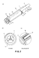
- Figure 2,(a), is a perspective view of the toner supply container in accordance with the present invention; Figure 2,(b) is a cross-sectional view of the toner supply container, as seen from the direction indicated by an arrow mark A in Figure 2,(a); and Figure 2,(c) is an enlarged perspective view of the portion of the toner supply container, which is surrounded by the circle designated by a referential character B in Figure 2,(a).
- Figure 3, (a) is an external perspective view of the toner receiving apparatus in accordance with the present invention; Figure 3, (b) is a perspective view of the toner supply container bay of the toner receiving apparatus, the toner receiving opening of which is closed; and Figure 3, (c) is a perspective view of the toner supply container bay of the toner receiving apparatus, the toner receiving opening of which is open.
- Figure 4 is a perspective view of the toner receiving apparatus and toner supply container, in accordance with the present invention, showing how the latter is mounted into the former.
- Figure 5 is cross-sectional views of the toner supply container in accordance with the present invention, showing the operation for discharging toner, wherein (a) illustrates the toner supply container immediately after the mounting of the container, (b) is an enlarged view of a portion A indicated in (a), (c) illustrates the toner supply container during discharging of the toner, and (d) is an enlarged view of a portion B in indicated in (c).
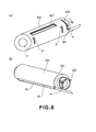
- Figure 6 illustrates a toner supply container according to another embodiment of the present invention, wherein (a) is a perspective view of the toner supply container, and (b) is a perspective view of an internal cylinder.
- Hereafter, the preferred embodiments of the present invention will be described in detail with reference to the appended drawings. Incidentally, the measurements, materials, shapes of the structural components described in the following embodiments of the present invention, and the positional relationship among the structural components, are not intended to limit the scope of the present invention, unless specifically noted. That is, the preferred embodiments are modifiable, as fits, according to the structure of an apparatus to which the present invention is applied, and the various conditions under which the apparatus to which the present invention is applied is operated.
- First, referring to Figure 1, an electrophotographic copying machine, as an example of an electrophotographic image forming apparatus, which is a developer receiving apparatus in which a toner supply container, as a developer supply container, is mounted, will be described regarding its structure.
- In Figure 1, designated by a
referential numeral 100 is a main assembly of the electrophotographic copying machine (which hereafter will be referred to as apparatus main assembly). Designated by areferential numeral 101 is an original, which is placed on an originalplacement glass platen 102. An optical image in accordance with the picture information is focused on an electrophotographicphotosensitive drum 104 by the multiple mirrors and a lens Ln of anoptical portion 103. - Designated by referential numerals 105 - 108 are cassettes in which sheets P of recording medium (which hereafter may be referred to as recording paper P) are stored. Among the recording mediums P stored in layers in these cassettes 105 - 108, the optimal recording medium P is selected based on the information inputted by a user through the control panel of the apparatus main assembly, the size of the original 101, and the information regarding the size of the recording medium P stored in each of the cassettes 105 - 108. The choice of the recording medium P is not limited to recording paper. For example, the apparatus can be used with an OHP sheet or the like. In other words, the choice of recording medium is optional.
- Each of the sheets of recording paper P conveyed by feeding-and-separating
apparatuses 105A - 108A is conveyed to a pair ofregistration rollers 110 by way of aconveyance path 109. Then, the pair ofregistration rollers 110 releases forward the sheet of recording paper P in synchronization with the rotation of thephotosensitive drum 104 and the scanning timing of theoptical portion 103. - Designated by
referential numerals transfer discharger 111 is a discharger for electrostatically transferring a toner image formed on the peripheral surface of thephotosensitive drum 104, onto the sheet of recording paper P. Theseparation discharger 112 is a discharger for removing the electric charge from the sheet of recording medium P when separating the sheet of recording paper P from thephotosensitive drum 104 after the transfer of the toner image onto the sheet of recording paper P. - After being separated from the
photosensitive drum 104, the sheet of recording paper P is conveyed by a conveyingportion 113 to afixation station 114. In thefixation station 114, the sheet of recording paper P and the unfixed toner image thereon are subjected to heat and pressure. As a result, the unfixed image is fixed to the surface of the sheet of recording medium P. Then, when the copying machine is in the single-sided copying mode, the sheet of recording paper P is discharged by a pair ofdischarge rollers 116 into adelivery tray 117. However, when the copying machine is in the two-sided copying mode, theflapper 118 of a discharging-or-reversingstation 115 is controlled so that the sheet of recording paper P is conveyed to the pair ofregistration rollers 110 by way of refeeding-and-conveyingportions delivery tray 117. - When the copying machine is in the multilayer copying mode, the sheet of recording paper P is conveyed outward through the discharging-or-
reversing station 115 by the pair ofdischarge rollers 116, by a distance large enough for the sheet of recording paper P to be partially exposed from the apparatus main assembly, that is, until the trailing edge of the sheet of recording paper P reaches the area between theflapper 118 and pair ofdischarge rollers 116. Then, while the sheet of recording paper P remains pinched between the pair ofdischarge rollers 116, theflapper 118 is controlled and thedischarge rollers 116 are rotated in reverse. As a result, the sheet of recording paper P is conveyed back into the apparatus main assembly. Then, the sheet of recording paper P is conveyed to the pair ofregistration rollers 110 by way of the refeeding-and-conveyingportions delivery tray 117. - Regarding back to the apparatus
main assembly 100 structured as described above, in the adjacencies of the peripheral surface of thephotosensitive drum 104, adevelopment station 201, acleaning station 202, aprimary charger 203, etc., are disposed. - The
development station 201 is a station which develops an electrostatic latent image formed on the peripheral surface of thephotosensitive drum 104 by theoptical portion 103, based on the information regarding the original 101, with the use of toner as developer. The apparatusmain assembly 100 is holding atoner supply container 1 for supplying toner to thedevelopment station 201. Thetoner supply container 1 is removably mountable in the apparatusmain assembly 100 by a user. - The
development station 201 has atoner receiving apparatus 7 in which thetoner supply container 1 is removably mountable, and a developingdevice 201a. The developingdevice 201a has adevelopment roller 201b and adeveloper sending member 201c. Toner is supplied from thetoner supply container 1 into the developingdevice 201a. Then, the toner is sent by thetoner sending member 201c to thedevelopment roller 201b, by which the toner is supplied to the electrostatic latent image formed on the peripheral surface of thephotosensitive drum 104. - The
cleaner 202 is a device for removing the toner remaining on the peripheral surface of thephotosensitive drum 104. Theprimary charger 203 is a device for charging thephotosensitive drum 104. - The apparatus
main assembly 100 is provided with a toner supplycontainer bay cover 15, which also functions as a part of the external cover of the apparatus main assembly. When a user wants to replace thetoner supply container 1, the user is to open the toner supplycontainer bay cover 15 in the direction indicated by an arrow mark A. - Next, referring to Figures 2(a) - 2(c), the
toner supply container 1, as a developer supply container, will be described regarding its structure. - The container proper 1a of the
toner supply container 1, which is the actual storage portion of thetoner supply container 1, is roughly in the form of a hollow cylinder. The cylindrical portion of the container proper 1a is provided with anopening 1b, as a toner outlet, which is roughly in the form of a long and narrow rectangle, the long edges of which are parallel to the lengthwise direction of thecontainer 1. - When the
toner supply container 1 has never been used, theopening 1b is airtightly sealed with aseal 9 formed of film (which hereafter will be referred to as sealing film 9). The sealingfilm 9 is longer than twice the length of theopening 1b; the sealingfilm 9 is welded to the container proper 1a, from one end of the opening to the other, in terms of the lengthwise direction of thetoner supply container 1, in a manner to seal theopening 1b, is folded back to the starting end, and is extended beyond the starting end. The sealingfilm 9 is to be peeled away by a user after the mounting of thetoner supply container 1 into thetoner receiving apparatus 7, which will be described later; as the user pulls the sealingfilm 9 by grasping the portion of the sealingfilm 9, which is extending outward beyond the aforementioned starting end of the sealingfilm 9, theopening 1b is exposed. - Incidentally, the sealing
film 9 in this embodiment is designed so that it is to be peeled away from the container proper 1a to expose theopening 1b. However, the sealingfilm 9 may be designed as follows. - For example, the sealing
film 9 may be provided with a pair of tear guides (tear lines) so that as the sealingfilm 9 is pulled, it easily tears along the pair of tear guides. These tear guides can be formed by thinning the sealingfilm 9 along preset lines on thesealing film 9 by exposing the portions of the sealingfilm 9, which correspond to the preset lines, to a beam of laser light. The method for thinning the sealingfilm 9 along the preset lines may be a method other than the abovementioned laser-based one. - The sealing
film 9 is provided to prevent toner from leaking from a developer supply container while the developer supply container is distributed. More specifically, the sealingfilm 9 is provided to prevent toner from leaking from a developer supply container, when a certain amount of changes occurs to the ambience of the developer supply container (changes in temperature, humidity, and atmospheric pressure), during the distribution of the developer supply container. Moreover, the sealingfilm 9 prevents the toner from leaking from the developer supply container due to the vibrations of the developer supply container, which occur during the distribution of the developer supply container, and/or due to the impacts which might occur if the developer supply container happens to fall during its distribution. - However, even if the container proper is sealed with the sealing
film 9, the toner leak occurs sometimes, for example, if the changes in the ambience of the developer supply container, which occur during the distribution of the developer supply container, are rather large, and/or the impacts which result from the falling of the developer supply container during the distribution of the developer supply container are severe. - Thus, the role of the sealing
film 9 in this embodiment is to prevent the toner leak, within a reasonable range of changes in the ambience of a developer supply container which the developer supply container might encounter during its distribution. In other words, in the following description of the preferred embodiments of the present invention, prevent toner leak means to prevent the toner leak, within the reasonable range of the changes in the ambience of the developer supply container, which the developer supply container might encounter during the distribution of the developer supply container. - As the method for attaching the sealing
film 9 to the container proper 12, the welding method which uses a heated plate, impulse, ultrasonic waves, or, high frequency waves, the bonding method which uses ordinary adhesive or hot-melt adhesive, the method which uses two-sided adhesive tape, or the like can be used. In this embodiment, the method which uses a heated plate is employed. - The
toner supply container 1 is provided with a sealingmember 10, which is an elastic member 10 (elastic seal) attached to the container proper 1a in a manner to surround theopening 1b. The sealingmember 10 is provided to practically completely prevent the toner from entering the gap between thetoner supply container 1 andtoner receiving apparatus 7, when the toner is supplied from thetoner supply container 1 into thetoner receiving apparatus 7. More specifically, the sealingmember 10 is remains compressed by a preset amount between the container proper 1a and container shutter. Thus, it prevents the toner from entering the abovementioned gap, by playing the role of bridging the gap between thetoner supply container 1 andtoner receiving apparatus 7. Incidentally, here, toner entry is prevented means not only the case that the toner entry is perfectly prevented, but also, the case that toner enters the abovementioned gap by an amount which is practically too small to cause a problem. - Parenthetically, the sealing
member 10 is a member which plays its role after the peeling of the sealingfilm 9. In order to optimally fill the gap between the toner supply container andtoner receiving apparatus 7, it is desired to be along the edge of theopening 1b that the sealingmember 10 is attached to the container proper 1a. - Therefore, it is desired that before the sealing
member 9 is attached to the container proper 1a, the sealingmember 10 is fixed to the container proper 1a, and then, the sealingfilm 9 is attached to the container proper 1a in a manner to cover the sealingmember 10 as well as its adjacencies, as shown in Figure 2(c). - Thus, in this embodiment, the
portion 9a of the sealingfilm 9, by which thesealing film 9 is welded to the container proper 1a, is patterned so that as the sealingmember 9 is welded to the container proper 1a, theportion 9a of the sealingfilm 9 surrounds the sealingmember 10. The employment of the abovementioned structural arrangement can prevent the sealingmember 10 from being damaged when the sealingfilm 9 is peeled off. That is, it can prevent the sealingmember 10 from being reduced in its performance of keeping sealed the aforementioned gap when toner is supplied from thetoner supply container 1 to thetoner receiving apparatus 7. Further, the sealingfilm 9 is also given the function of protecting the surface of the sealingmember 10. That is, in the case of the above described structural arrangement in this embodiment, the sealingfilm 9 can prevent the sealingmember 10 from deteriorating until thetoner supply container 1 is used for the first time to supply thetoner receiving apparatus 7 with toner. - In consideration of the frictional pressure between the sealing
member 10 and the wall of thetoner receiving apparatus 7, the material for the sealingmember 10 is desired to be low in density. More specifically, a foamed substance such as high density polyurethane foam, woven or unwoven fabric based on animal fiber such as wool or silk, plant fiber such as cotton or linen, or synthetic fiber such as Nylon, polyester, acrylic, may be listed. From the standpoint of compressibility, it is desired to use a foamed substance as the material for the sealingmember 10. In this embodiment, high density polyurethane foam is used as the material for the sealing member 50. - Referring to Figure 2(a), the
toner supply container 1 is provided with acontainer shutter 3, the curvature of which matches that of the peripheral surface of the container proper 1a of thetoner supply container 1, and which is attached to thetoner supply container 1 so that it can cover theopening 1b. Prior to the removal of the sealingfilm 9, the sealingfilm 9 remains covered by thecontainer shutter 3. Thiscontainer shutter 3 is engaged with a pair of guidingmembers 1d, which are disposed at the lengthwise ends of the container proper 1a, one for one. Thetoner supply container 1 is structured so that thecontainer shutter 3 can be slid in the circumferential direction of the container proper 1a, following the peripheral surface of the container proper 1a. - In terms of the lengthwise direction of the container proper 1a, one of the end walls of the container proper 1a is provided with an
opening 1c as a toner inlet, which is sealed with an unshown cap or the like after thetoner supply container 1 is filled with toner. - Further, the
toner supply container 1 is provided with ahandle 2, as a hand grip, which is for a user to grasp when mounting or dismounting thetoner supply container 1. Thehandle 2 is attached to one of the lengthwise ends of thetoner supply container 1. The shape of thehandle 2 does not need to be limited to that in this embodiment. That is, any shape is acceptable as long as it makes thehandle 2 usable for mounting or dismounting thetoner supply container 1, and also, sufficiently useful for rotating thetoner supply container 1. - The container proper 1a is provided with a conveying
member 4, which is disposed within the hollow of the container proper 1a. This conveyingmember 4 is made up of a rotational shaft and stirring blades. The axial line of the rotational shaft coincides with that of the coupling which will be described later. The stirring blades are attached to the rotational shaft. The stirring blades have the function of conveying the toner in the container proper 1a toward theopening 1b, and also, the function of stirring the toner. - Further, the
toner supply container 1 is provided with acoupling 5, which is located at the opposite lengthwise end of the container proper 1a from where thehandle 2 is located. Thecoupling 5 is connected to the conveyingmember 4 so that as thecoupling 5 is rotated, the conveyingmember 4 is rotated by the rotation of thecoupling 5. In this embodiment, the rotational shaft of the conveyingmember 4 andcoupling 5 are integrally molded of resin. - The
coupling 5 is enabled to engage with the coupling mechanism of the apparatusmain assembly 100. The apparatus main assembly andtoner supply container 1 are structured so that thecoupling 5 receives rotational driving force when toner can be discharged from thetoner supply container 1 set in the image forming apparatus main assembly. - As rotational driving force is transmitted to the conveying
member 4 throughcoupling 5, the conveyingmember 4 rotates relative to thetoner supply container 1 which is practically nonrotatively anchored to the apparatus main assembly. As a result, the toner in thetoner supply container 1 is conveyed, while being stirred, by the conveyingmember 4 toward theopening 1b, and then, is discharged through theopening 1b. - Incidentally, the
toner supply container 1 does not need to be immovably anchored to the apparatus main assembly. That is, it does not matter as long as the apparatus main assembly andtoner supply container 1 are structured so that thetoner supply container 1 is prevented by the apparatus main assembly, at least from being rotated by the rotation of the conveyingmember 4 in the same direction as the rotational direction of the conveyingmember 4. - Next, referring to Figures 3(a) - 3(c), the
toner receiving apparatus 7, as the developer receiving apparatus on the image forming apparatus main assembly side, will be described regarding its structure. - The
toner receiving apparatus 7 is provided with abay 7a (storage space) in which thetoner supply container 1 is removably mounted, and atoner receiving opening 7b, through which the toner discharged from thetoner supply container 1 is received into the image forming apparatus main assembly. - The
toner receiving apparatus 7 is also provided with anapparatus shutter 8, which can repeatedly seal or unseal thetoner receiving opening 7b. The curvature of theapparatus shutter 8 matches the curvature of the peripheral surface of thetoner supply container 1 and the curvature of the wall of the tonersupply container bay 7a. It is connected to a guiding member (unshown) located at the bottom edge of the tonersupply container bay 7a. The employment of the above described structural arrangement makes it possible for theapparatus shutter 8 to be slid in the circumferential direction of the tonersupply container bay 7a to expose or cover thetoner receiving opening 7b (Figure 3(b) - Figure 3(c)). - Referring to Figure 3(b), when the
toner supply container 1 is not in the tonersupply container bay 7a, the adjacency of the edge (top edge in Figure 3(b)) of thisapparatus shutter 8 is in contact with the astopper 7c with which thetoner receiving apparatus 7 is provided, being thereby prevented from rotating beyond thestopper 7c. That is, thetoner receiving opening 7b remains closed by theapparatus shutter 8, preventing toner from flowing back from the image forming apparatus main assembly side to the tonersupply container bay 7a side. - Next, referring to Figures 3(b) and 3(c), the
apparatus shutter 8 is also provided with aconnective portion 8a, which connects with theconnective portion 6 of thetoner supply container 1. - As for the connection of the
connective portion 6 of thetoner supply container 1 to theconnective portion 8a of theapparatus shutter 8, the rotation of the toner supply container 1 (in terms of circumferential direction of toner supply container 1) from the position in thetoner receiving apparatus 7, into or from which thetoner supply container 1 is mounted or dismounted, respectively, to the toner supplying position into which thetoner supply container 1 is rotated by a preset angle, connects theconnective portion 6 of thetoner supply container 1 to theconnective portion 8a of theapparatus shutter 8. - Next, referring to Figures 4, and 5(a) - 5(d), the operation for setting up the
toner supply container 1 in the apparatus main assembly or extracting it from the apparatus main assembly will be described. The Figure 5(b) and 5(d) are enlarged views of the adjacencies of theopenings 1b shown in Figures 5(a) and Figure 5(c), respectively. - First, a user is to grasp the
handle 2 and insert thetoner supply container 1 into thetoner receiving apparatus 7. More concretely, thetoner supply container 1 is to be mounted into thetoner receiving apparatus 7 from the direction indicated by an arrow mark A (Figure 4). - During the mounting of the
toner supply container 1 into thetoner receiving apparatus 7, theopening 1b of thetoner supply container 1 is facing upward, remaining sealed with the sealingfilm 9, and theshutter 3 is in the closed position (Figure 5(b)). - That is, the
opening 1b of thetoner supply container 1 is in the position, which is apart from thetoner receiving opening 7b remaining sealed with theapparatus shutter 8, in terms of the rotational direction of thetoner supply container 1. Further, theconnective portion 6 of thetoner supply container 1 is also in the position, which is apart from theconnective portion 8a of theshutter 8, in terms of the rotational direction of the toner supply container 1 (Figure 5(a)). - Next, the user is to pull the outwardly extending end portion of the sealing
film 9 in the direction indicated by an arrow mark C (Figure 2(a)), to peel thesealing film 9. - Then, the user is to grasp the
handle 2 and rotate thetoner supply container 1 in the counterclockwise direction (X direction in Figure 5(a)), as seen from the direction of the opening 1c as the toner inlet. - Incidentally, the
toner supply container 1 and apparatus main assembly are structured so that when thetoner supply container 1 is rotated, the rotation of thecontainer shutter 3 in the circumferential direction of thetoner supply container 1 is regulated by thestopper 7c. - That is, during the initial stage of the rotation of the
toner supply container 1 in the direction X, thecontainer shutter 3 moves with thetoner supply container 1. However, as thetoner supply container 1 is further rotated in the direction X, thecontainer shutter 3 comes into contact with the above describedstopper 7c, being therefore prevented from rotating further. - Then, as the
toner supply container 1 is further rotated in the same direction, theconnective portion 6 of thetoner supply container 1 engages with theconnective portion 8a of theapparatus shutter 8. Then, as thetoner supply container 1 is further rotated, theapparatus shutter 8 is pushed by theconnective portion 6, being thereby forced to rotate with thetoner supply container 1. As a result, thetoner receiving opening 7b is exposed; thetoner receiving opening 7b becomes connected to theopening 1b (Figure 5(c) and 5(d)). - The
toner supply container 1 and apparatus main assembly are structured so that only when thetoner receiving opening 7b is in connection with theopening 1b, thecoupling 5 of thetoner supply container 1 receives driving force from the coupling mechanism on the image forming apparatus main assembly side, and transmits the received driving force to the conveyingmember 4, supplying thereby thetoner receiving apparatus 7 with the toner from thetoner supply container 1. Further, when thetoner receiving opening 7b is in connection with theopening 1b, the gap between thetoner supply container 1 and the wall of thetoner receiving apparatus 7 is filled with the sealingmember 10, preventing thereby the toner from entering from thetoner receiving opening 7b and/oropening 1b into this gap. - After the completion of the toner supplying process, the user is to grasp the
handle 2 and rotate thetoner supply container 1 in the clockwise direction (direction Y in Figure 5(c)), as seen from the direction of the opening 1c as the toner inlet. During the initial stage of the rotation, theconnective portion 8a of theapparatus shutter 8 remains connected to theconnective portion 6 of thetoner supply container 1, being therefore pulled upward by theconnective portion 6. Therefore, theconnective portion 8a rotates with thetoner supply container 1. - As the
toner supply container 1 is further rotated, theapparatus shutter 8 comes into contact with thestopper 7c, being thereby prevented from moving further with thetoner supply container 1. As a result, theconnective portion 6 is forced to disconnect from theconnective portion 8a of theapparatus shutter 8. - As the
toner supply container 1 is further rotated, theopening 1b and sealingmember 10 is covered by thecontainer shutter 3, the clockwise rotation of which is regulated by thetoner receiving apparatus 7. Then, in the final stage of the clockwise rotation of thetoner supply container 1, the positional relationship among the above described components of thetoner supply container 1 andtoner receiving apparatus 7 becomes as shown in Figure 5(a). - Lastly, the user is to pull the
toner supply container 1 out of thetoner receiving apparatus 7 to complete the operational sequence for resealing thetoner receiving opening 7b and theopening 1b as the toner outlet, and extracting thetoner supply container 1 from thetoner receiving apparatus 7. - Incidentally, in this embodiment, it is from the front side of the apparatus main assembly that the
toner supply container 1 is mounted into thetoner receiving apparatus 7. However, the direction from which thetoner supply container 1 is mounted into thetoner receiving apparatus 7 does not need to be limited to the front side of the apparatus main assembly. For example, thetoner supply container 1 and apparatus main assembly may be structured so that thetoner supply container 1 is mounted into, or dismounted from, thetoner receiving apparatus 7, on the top side of the apparatus main assembly. - Also in this embodiment, the
toner supply container 1 and apparatus main assembly are structured so that when theopening 1b is facing in the horizontal direction, it is in connection with thetoner receiving opening 7b of the wall of thetoner receiving apparatus 7, the angular position of which relative to the vertical direction is roughly 90°. However, they do not need to be structured as they are in this embodiment. - Further, the direction in which the
toner supply container 1 is rotated when it is set in thetoner receiving apparatus 7 does not need to be limited to the abovementioned direction. For example, thetoner supply container 1 and apparatus main assembly may be structured so that theopening 1b faces downward when thetoner supply container 1 is mounted into thetoner receiving apparatus 7, and thetoner supply container 1 is rotated in the opposite direction from the direction in which thetoner supply container 1 is rotated in this embodiment, for the purpose of unsealing; and is rotated in the direction opposite from that of the embodiment for the purpose of resealing. - When the above described structural arrangement was employed, toner did not leak from the
opening 1b during the distribution of thetoner supply container 1, or in the like situation. Further, after the sequence of setting thetoner supply container 1 in thetoner receiving apparatus 7 and taking it out of thetoner receiving apparatus 7 is carried out one time, there was virtually no confirmable contamination of thetoner supply container 1 andtoner receiving apparatus 7 by toner. This was true even after the same sequence was repeated twenty times. - As was evident from the description of this embodiment given above, the structural arrangement in this embodiment can prevent the contamination attributable toner during the distribution of the
toner supply container 1, as well as while thetoner receiving apparatus 7 is supplied with toner by thetoner supply container 1. In other words, it can prevent a user from being contaminated by the toner which has adhered to thetoner supply container 1. - Incidentally, in the embodiment described above, the sealing
member 10 is attached to the container proper 1a of thetoner supply container 1. However, the sealingmember 10 may be attached to the container shutter side. In such a case, the sealingfilm 9 is attached to the container proper 1a, without covering the sealingmember 10 as it does in this embodiment. - Next, referring to Figure 6, the toner supply container in this embodiment will be described. Incidentally, the toner supply container in this embodiment is the same in structure as that in the above described first embodiment, except for the part of the toner supply container, which will be described later. Further, the components, parts, etc., of the toner supply container in this embodiment, which are the same in function as those in the first embodiment are given the same referential numerals as those given to describe the first embodiment, and will not be described in detail.
- This preferred embodiment is different from the first preferred embodiment in that the structure, in this embodiment, for exposing or covering the
opening 1b is different from that in the first embodiment. More concretely, referring to Figure 6(a), the toner supply container in this embodiment has a double cylinder structure: it has aninternal cylinder 300, as a storage portion, in which toner is stored, and an external cylinder 400 (which hereafter may be referred to as shutter), which is rotatably fitted around theinternal cylinder 300. - Referring to Figure 6(b), this
internal cylinder 300 is provided with anopening 1b, which is similar to that in the first embodiment. Theinternal cylinder 300 is also provided with a sealingmember 10, which is attached to theinternal cylinder 300 in a manner to surround theopening 1b as it is in the first embodiment. Further, theinternal cylinder 300 is provided with a sealingfilm 9, which is attached to theinternal cylinder 300 in a manner to cover the sealingmember 10 as it does in the first embodiment. - In addition, the
internal cylinder 300 is provided with aconnective portion 302, which engages with the connective portion of the toner receiving apparatus to prevent theinternal cylinder 300 from rotating further after the engagement of theconnective portion 302 and the connective portion of the toner receiving apparatus. The peripheral surface of theinternal cylinder 300 is provided with aguide projection 301. - As for the
external cylinder 400, it is provided with aconnective opening 401, which is connectible to theopening 1b. Further, the cylindrical wall of theexternal cylinder 400 is provided with aguide slot 402, in which theguide projection 301 of theinternal cylinder 300 fits to be guided by theguide slot 402, preventing thereby the twocylinders external cylinder 400 rotates relative to theinternal cylinder 300. - As the toner supply container structured as described above is mounted into the toner receiving apparatus, it becomes possible for the
connective portion 302 of theinternal cylinder 300 to engage with the connective portion of the toner receiving apparatus. Immediately after the mounting of the toner supply container into the toner receiving apparatus, theopening 1b of theinternal cylinder 300 is roughly 90°apart from theconnective opening 401 of theexternal cylinder 400 in terms of the circumferential direction of the toner supply container, and thesealing film 9 is to be peeled at this point in time by an operator. - Thereafter, the operator is to rotate the
external cylinder 400 by a preset angle (which in this embodiment is roughly 90°) in the setup direction indicated by an arrow mark, relative to theinternal cylinder 300 which is nonrotatably held by the toner receiving apparatus. Thus, as theexternal cylinder 400 is rotated, theopening 1b of theinternal cylinder 300 becomes aligned with theconnective opening 401 of theexternal cylinder 400, that is, the opening of theexternal cylinder 400 and the opening of theinternal cylinder 300 become connected, making it possible for the toner receiving apparatus to be supplied with the toner from the toner supply container. - As for the sequence for taking the toner supply container out of the toner receiving apparatus, the toner supply container can be taken out of the toner receiving apparatus by carrying out in reverse the above described sequence for mounting the toner supply container into the toner receiving apparatus. That is, the operator is to rotates the
external cylinder 400 in the direction opposite to the setup direction by a preset angle (which in this embodiment is roughly 90°) to cover theopening 1b of theinternal cylinder 300. As theopening 1b is covered, it becomes possible for the operator to take the toner supply container out of the toner receiving apparatus. - As described above, in this embodiment, the role which the container shutter plays in the first embodiment is assumed by the
external cylinder 400. Moreover, the container shutter is opened by the rotation of theexternal cylinder 400, instead of the rotation of theinternal cylinder 300 as the toner storage portion. - The same effects as those obtained by the structural arrangement in the first preferred embodiment can also be obtained by the structural arrangement in this embodiment.
- Incidentally, in this embodiment, the sealing
member 10 is attached to the internal cylinder. However, the sealingmember 10 may be attached to the internal surface of the external cylinder. In such a case, the sealingmember 10 is attached to the internal surface of the external cylinder in a manner to surround the connective opening. This structural arrangement also can prevent the toner from leaking into the space between the internal and external cylinders, like the structural arrangement in this embodiment. Also in such a case, the sealingmember 10 may be attached to the area of the internal surface of the external cylinder, which surrounds theopening 1b of the internal cylinder when theopening 1b is covered with the external cylinder, that is, during the distribution of the toner supply container. - Further, in the first and second preferred embodiments described above, the container proper of the developer supply container was roughly cylindrical. However, these embodiments are not intended to limit the scope of the present invention. That is, the shape of the developer supply container may be different from the one in the preceding two embodiments, as long as the shape allows the developer supply container to store developer. For example, it may be polygonal in cross section.
- Also in the first and second preferred embodiments described above, the image forming apparatus (developer receiving apparatus) in accordance with the present invention was a copying machine. However, the present invention is also applicable to an image forming apparatus other than the copying machine. That is, it is also applicable to a printer, a facsimile machine, a multifunction apparatus having two or more functions of the preceding apparatuses, etc.
- Further, in the first and second preferred embodiments described above, the image forming apparatus in accordance with the present invention was an image forming apparatus (developer receiving apparatus) which forms a monochromatic image (black-and-white image). However, the image forming apparatus to which the present invention is applied is not limited to an image forming apparatus such as the above described one.
- For example, the image forming apparatus to which the present invention is applied may be a color image forming apparatus, which transfers in layers multiple toner images, different in color, onto the recording medium borne on the recording bearing member, from the photosensitive member, or a color image forming apparatus, which sequentially transfers in layers multiple developer images, different in color, onto the intermediary transfer member, from the photosensitive member, and transfers all at once the developer images on the intermediary transfer member, onto the recording medium.
- In other words, a developer supply container in accordance with the present invention can be employable by the various image forming apparatuses described above.
- Further, a developer supply container in accordance with the present invention may be structured so that it can supply developer to a process cartridge, as a developer receiving apparatus, which can be removably mountable in the main assembly of an image forming apparatus. That is, a developer supply container in accordance with the present invention may be structured so that it can be removably mounted into a process cartridge.
- Incidentally, a process cartridge, such as the one described above, may be provided with at least the developing
device 201a. Further, it may be provided with the electrophotographicphotosensitive member 104, as an image bearing member, in addition to the developingdevice 201a. Moreover, it may be provided with at least one of thecharging device 203 and cleaner 203 which are integrally disposed in the process cartridge to process thephotosensitive drum 104. - In the preceding portion of this specification, the present invention has been described with reference to the preferred embodiments of the present invention. It is needless to say, however, that the various structures in the preceding preferred embodiments are modifiable to render them compatible with the well-known structures, within the scope of the present invention.
- Next, comparative embodiments of the present invention will be described.
- In this comparative embodiment, the toner supply container is not provided with the sealing
film 9. Otherwise, the toner supply container is the same in structure as those in the preceding preferred embodiments. - In the case of the toner supply container in this comparative embodiment, toner leaked from the
opening 1b and contaminated thetoner supply container 1, during the distribution of the toner supply container. Therefore, carrying out the sequence for setting up thetoner supply container 1 and taking thetoner supply container 1 once was enough to badly contaminate thetoner receiving apparatus 7. - The results of the above described testing of the structural arrangement in this comparative embodiment confirmed the effectiveness of the toner supply container structures in the preferred embodiments.
- In this comparative embodiment, the
toner receiving apparatus 7 is provided with the sealingmember 10. Otherwise, the structural arrangement in this comparative embodiment is the same as those in the preceding preferred embodiments. - After the operation for setting up the
toner supply container 1 in the toner receiving apparatus and removing thetoner supply container 1 from the toner receiving apparatus is carried out only once, there was virtually no difference between this comparative embodiment and the preceding preferred embodiments, in terms of the level of contamination caused to thetoner supply container 1 and/ortoner receiving apparatus 7 by toner was. However, as the same operation was repeated twenty times, the toner having accumulated on the sealingmember 10 transferred onto thetoner supply container 1, worsening the contamination of thetoner supply container 1 attributable to toner. - The results of the above described testing of the structural arrangement in this comparative embodiment confirmed the effectiveness of the structural arrangements in the preferred embodiments of the present invention.
- While the invention has been described with reference to the structures disclosed herein, it is not confined to the details set forth and this application is intended to cover such modifications or changes as may come within the purpose of the improvements or the scope of the following claims.
- A developer supply container detachably mountable to a developer receiving apparatus, the developer supply container includes an containing portion for containing a developer; a discharge opening, provided in the containing portion, for permitting discharge of the developer; a shutter for opening and closing the discharge opening; an elastic member, provided around the discharge opening, for sealing between the developer supply container and the developer receiving apparatus; and a film member for unsealably sealing the discharge opening.
Claims (5)
- A developer supply container detachably mountable to a developer receiving apparatus, said developer supply container comprising:a containing portion for containing a developer;a discharge opening, provided in said containing portion, for permitting discharge of the developer;a shutter for opening and closing said discharge opening;an elastic member, provided around said discharge opening, for sealing between said developer supply container and said developer receiving apparatus; anda film member for unsealably sealing said discharge opening.
- A developer supply container according to Claim 1, wherein said film member is provided so as to surround said elastic member.
- A developer supply container according to Claim 1, wherein said film member is folded back toward a direction in which said film member is pulled by an operator.
- A developer supply container detachably mountable to a developer receiving apparatus, said developer supply container comprising:a containing portion for containing a developer;a discharge opening, provided in said containing portion, for permitting discharge of the developer;an elastic member, provided around said discharge opening, for sealing between said developer supply container and said developer receiving apparatus; anda film member, provided so as to surround said elastic member, for unsealably sealing said discharge opening.
- A developer supply container according to Claim 4, wherein said film member is folded back toward a direction in which said film member is pulled by an operator.
Applications Claiming Priority (1)
| Application Number | Priority Date | Filing Date | Title |
|---|---|---|---|
| JP2005323691 | 2005-11-08 |
Publications (2)
| Publication Number | Publication Date |
|---|---|
| EP1783563A1 true EP1783563A1 (en) | 2007-05-09 |
| EP1783563B1 EP1783563B1 (en) | 2010-08-18 |
Family
ID=37625998
Family Applications (1)
| Application Number | Title | Priority Date | Filing Date |
|---|---|---|---|
| EP06123622A Not-in-force EP1783563B1 (en) | 2005-11-08 | 2006-11-07 | Developer supply container with a shutter |
Country Status (6)
| Country | Link |
|---|---|
| US (2) | US7937018B2 (en) |
| EP (1) | EP1783563B1 (en) |
| JP (1) | JP4347331B2 (en) |
| KR (2) | KR100882982B1 (en) |
| CN (1) | CN100590541C (en) |
| DE (1) | DE602006016214D1 (en) |
Cited By (1)
| Publication number | Priority date | Publication date | Assignee | Title |
|---|---|---|---|---|
| EP2028561A3 (en) * | 2007-05-29 | 2014-06-18 | Fuji Xerox Co., Ltd. | Image forming apparatus and detachable body |
Families Citing this family (16)
| Publication number | Priority date | Publication date | Assignee | Title |
|---|---|---|---|---|
| PT1859323E (en) * | 2005-03-04 | 2014-07-16 | Canon Kk | Developer supply container and developer supplying system |
| US8023864B2 (en) * | 2007-04-27 | 2011-09-20 | Brother Kogyo Kabushiki Kaisha | Toner cartridge and developing apparatus |
| AU2011202765B2 (en) * | 2007-05-29 | 2012-05-24 | Fujifilm Business Innovation Corp. | Image forming apparatus and detachable body |
| JP4525782B2 (en) * | 2008-03-24 | 2010-08-18 | 富士ゼロックス株式会社 | Developer container and image forming apparatus |
| JP4553027B2 (en) * | 2008-03-27 | 2010-09-29 | ブラザー工業株式会社 | Developer cartridge, developing device, and image forming apparatus |
| JP5078847B2 (en) * | 2008-11-13 | 2012-11-21 | キヤノン株式会社 | Developer supply container |
| JP5106372B2 (en) * | 2008-12-17 | 2012-12-26 | キヤノン株式会社 | Developer supply container |
| JP4894868B2 (en) | 2009-02-23 | 2012-03-14 | 富士ゼロックス株式会社 | Container, supply device, and image forming apparatus |
| US8380102B2 (en) * | 2010-05-28 | 2013-02-19 | Lexmark International, Inc. | Tubular skiving seal for a rotary toner metering mechanism |
| ES2711352T3 (en) * | 2010-06-11 | 2019-05-03 | Ricoh Co Ltd | Information storage device, removable device, developer container and image forming device |
| US9207574B2 (en) * | 2011-03-31 | 2015-12-08 | Ricoh Company, Ltd. | Powder material container and image forming apparatus provided therewith, and powder material replenishing method |
| JP6083954B2 (en) | 2011-06-06 | 2017-02-22 | キヤノン株式会社 | Developer supply container and developer supply system |
| US8666277B2 (en) * | 2012-05-02 | 2014-03-04 | General Plastic Industrial Co., Ltd. | Developer supply container |
| JP6116253B2 (en) * | 2013-01-11 | 2017-04-19 | キヤノン株式会社 | Developer storage unit, developing device, process cartridge, and image forming apparatus including the same |
| JP2016206523A (en) * | 2015-04-27 | 2016-12-08 | 京セラドキュメントソリューションズ株式会社 | Image forming apparatus having developer containing container, developer containing container mounted on image forming apparatus |
| JP6950655B2 (en) * | 2018-09-28 | 2021-10-13 | ブラザー工業株式会社 | Image forming device |
Citations (2)
| Publication number | Priority date | Publication date | Assignee | Title |
|---|---|---|---|---|
| US5822653A (en) | 1994-10-21 | 1998-10-13 | Ricoh Company, Ltd. | Toner cartridge avoiding spillage of toners |
| US6324371B1 (en) | 1999-07-30 | 2001-11-27 | Oki Data Corporation | Toner cartridge |
Family Cites Families (19)
| Publication number | Priority date | Publication date | Assignee | Title |
|---|---|---|---|---|
| JPS60147767A (en) | 1984-01-11 | 1985-08-03 | Konishiroku Photo Ind Co Ltd | Case of powdery particle |
| SE459724B (en) * | 1987-12-08 | 1989-07-31 | Larson Prod Ab Ove | SETTING AND DEVICE MAKING A LATENT ELECTRIC CHARGING PATTERN |
| JP2541650B2 (en) * | 1989-01-27 | 1996-10-09 | キヤノン株式会社 | Developer supply container |
| JP3308671B2 (en) * | 1993-08-10 | 2002-07-29 | キヤノン株式会社 | Seal member, developer container, and process cartridge |
| JPH1048938A (en) | 1996-04-29 | 1998-02-20 | Brother Ind Ltd | Toner storage device, toner box, and toner supply method |
| JP3445069B2 (en) * | 1996-07-24 | 2003-09-08 | キヤノン株式会社 | Developing unit, process cartridge, and image forming apparatus |
| JP3883742B2 (en) * | 1999-06-24 | 2007-02-21 | 株式会社リコー | container |
| KR100718442B1 (en) | 2000-07-06 | 2007-05-14 | 한국후지제록스 주식회사 | Toner cartridges for image development |
| ES2433741T3 (en) * | 2001-02-19 | 2013-12-12 | Canon Kabushiki Kaisha | Container for toner supply and toner supply system |
| US6990301B2 (en) * | 2001-02-19 | 2006-01-24 | Canon Kabushiki Kaisha | Sealing member, toner accommodating container and image forming apparatus |
| JP3987324B2 (en) * | 2001-11-16 | 2007-10-10 | 株式会社白崎コーポレーション | Developer container seal |
| JP2003156927A (en) | 2001-11-21 | 2003-05-30 | Canon Inc | Toner supply container and toner stirring blade |
| JP4208521B2 (en) | 2002-08-26 | 2009-01-14 | キヤノン株式会社 | Developer supply container |
| CN2630903Y (en) * | 2003-03-18 | 2004-08-04 | 珠海天威飞马打印耗材有限公司 | Carbon dust box |
| JP2004317995A (en) * | 2003-04-21 | 2004-11-11 | Canon Inc | Toner seal member and process cartridge |
| JP4343625B2 (en) * | 2003-08-29 | 2009-10-14 | キヤノン株式会社 | Developer supply container |
| JP4693393B2 (en) * | 2003-11-19 | 2011-06-01 | キヤノン株式会社 | Developer supply device |
| JP2005274862A (en) | 2004-03-24 | 2005-10-06 | Canon Inc | Developer supply container |
| US7450890B2 (en) * | 2004-11-12 | 2008-11-11 | Canon Kabushiki Kaisha | Developer supply container having a shutter cleaning feature |
-
2006
- 2006-09-27 JP JP2006262851A patent/JP4347331B2/en not_active Expired - Fee Related
- 2006-11-01 US US11/555,399 patent/US7937018B2/en not_active Expired - Fee Related
- 2006-11-07 KR KR1020060109193A patent/KR100882982B1/en not_active Expired - Fee Related
- 2006-11-07 DE DE602006016214T patent/DE602006016214D1/en active Active
- 2006-11-07 EP EP06123622A patent/EP1783563B1/en not_active Not-in-force
- 2006-11-08 CN CN200610143966A patent/CN100590541C/en not_active Expired - Fee Related
-
2008
- 2008-11-12 KR KR1020080112425A patent/KR20080103946A/en not_active Withdrawn
-
2011
- 2011-03-21 US US13/052,604 patent/US8718509B2/en not_active Expired - Fee Related
Patent Citations (2)
| Publication number | Priority date | Publication date | Assignee | Title |
|---|---|---|---|---|
| US5822653A (en) | 1994-10-21 | 1998-10-13 | Ricoh Company, Ltd. | Toner cartridge avoiding spillage of toners |
| US6324371B1 (en) | 1999-07-30 | 2001-11-27 | Oki Data Corporation | Toner cartridge |
Cited By (1)
| Publication number | Priority date | Publication date | Assignee | Title |
|---|---|---|---|---|
| EP2028561A3 (en) * | 2007-05-29 | 2014-06-18 | Fuji Xerox Co., Ltd. | Image forming apparatus and detachable body |
Also Published As
| Publication number | Publication date |
|---|---|
| US8718509B2 (en) | 2014-05-06 |
| CN100590541C (en) | 2010-02-17 |
| US7937018B2 (en) | 2011-05-03 |
| EP1783563B1 (en) | 2010-08-18 |
| KR100882982B1 (en) | 2009-02-12 |
| CN1963687A (en) | 2007-05-16 |
| DE602006016214D1 (en) | 2010-09-30 |
| US20070104505A1 (en) | 2007-05-10 |
| KR20070049573A (en) | 2007-05-11 |
| JP4347331B2 (en) | 2009-10-21 |
| US20110200357A1 (en) | 2011-08-18 |
| KR20080103946A (en) | 2008-11-28 |
| JP2007156427A (en) | 2007-06-21 |
Similar Documents
| Publication | Publication Date | Title |
|---|---|---|
| US8718509B2 (en) | Developer supply container | |
| KR100687688B1 (en) | Developer supply container | |
| EP1533664B1 (en) | Developer supply container | |
| US6560422B2 (en) | Development cartridge, process cartridge, and electrophotographic image forming apparatus, and toner seal member for unsealing an opening for supplying developer by automatically winding up the toner seal member | |
| CN101046657B (en) | Toner replenishing device, image forming device, and toner shortage detection method | |
| EP1542088A1 (en) | Image forming device, powder feeding device, toner storage container, powder storage container, and method of recycling the containers | |
| US7450890B2 (en) | Developer supply container having a shutter cleaning feature | |
| US6971421B2 (en) | Developer supply container | |
| US6978107B2 (en) | Developer supply container | |
| JP2016102986A (en) | Cartridge and image forming apparatus | |
| JP2008020679A (en) | Toner container, toner supply device, and image forming apparatus | |
| JP2002357946A (en) | Toner supply container, toner supply device and sealing member | |
| JP2003066704A (en) | Sealing member, toner supply container and toner supply device | |
| JP2003173076A (en) | Developing device and developing cartridge | |
| JPH0418578A (en) | Toner cartridge | |
| RU2349948C2 (en) | Cartridge to feed developer | |
| JPH11184226A (en) | Developer container and image forming apparatus | |
| JPH0545733U (en) | Image forming device | |
| JPH08240978A (en) | Image forming device | |
| JP2004125831A (en) | Process cartridge and image forming apparatus | |
| JPH0926695A (en) | Developer supply container, process cartridge and image forming apparatus |
Legal Events
| Date | Code | Title | Description |
|---|---|---|---|
| PUAI | Public reference made under article 153(3) epc to a published international application that has entered the european phase |
Free format text: ORIGINAL CODE: 0009012 |
|
| AK | Designated contracting states |
Kind code of ref document: A1 Designated state(s): AT BE BG CH CY CZ DE DK EE ES FI FR GB GR HU IE IS IT LI LT LU LV MC NL PL PT RO SE SI SK TR |
|
| AX | Request for extension of the european patent |
Extension state: AL BA HR MK YU |
|
| 17P | Request for examination filed |
Effective date: 20071109 |
|
| AKX | Designation fees paid |
Designated state(s): CH DE FR GB IT LI |
|
| 17Q | First examination report despatched |
Effective date: 20081202 |
|
| GRAP | Despatch of communication of intention to grant a patent |
Free format text: ORIGINAL CODE: EPIDOSNIGR1 |
|
| GRAS | Grant fee paid |
Free format text: ORIGINAL CODE: EPIDOSNIGR3 |
|
| GRAA | (expected) grant |
Free format text: ORIGINAL CODE: 0009210 |
|
| AK | Designated contracting states |
Kind code of ref document: B1 Designated state(s): CH DE FR GB IT LI |
|
| REG | Reference to a national code |
Ref country code: GB Ref legal event code: FG4D |
|
| REG | Reference to a national code |
Ref country code: CH Ref legal event code: NV Representative=s name: BOVARD AG PATENTANWAELTE Ref country code: CH Ref legal event code: EP |
|
| REF | Corresponds to: |
Ref document number: 602006016214 Country of ref document: DE Date of ref document: 20100930 Kind code of ref document: P |
|
| REG | Reference to a national code |
Ref country code: CH Ref legal event code: PFA Owner name: CANON KABUSHIKI KAISHA Free format text: CANON KABUSHIKI KAISHA#30-2, SHIMOMARUKO 3-CHOME#OHTA-KU, TOKYO 146-8501 (JP) -TRANSFER TO- CANON KABUSHIKI KAISHA#30-2, SHIMOMARUKO 3-CHOME#OHTA-KU, TOKYO 146-8501 (JP) |
|
| PLBE | No opposition filed within time limit |
Free format text: ORIGINAL CODE: 0009261 |
|
| STAA | Information on the status of an ep patent application or granted ep patent |
Free format text: STATUS: NO OPPOSITION FILED WITHIN TIME LIMIT |
|
| 26N | No opposition filed |
Effective date: 20110519 |
|
| REG | Reference to a national code |
Ref country code: DE Ref legal event code: R097 Ref document number: 602006016214 Country of ref document: DE Effective date: 20110519 |
|
| REG | Reference to a national code |
Ref country code: FR Ref legal event code: PLFP Year of fee payment: 10 |
|
| REG | Reference to a national code |
Ref country code: FR Ref legal event code: PLFP Year of fee payment: 11 |
|
| REG | Reference to a national code |
Ref country code: FR Ref legal event code: PLFP Year of fee payment: 12 |
|
| PGFP | Annual fee paid to national office [announced via postgrant information from national office to epo] |
Ref country code: FR Payment date: 20191126 Year of fee payment: 14 Ref country code: IT Payment date: 20191122 Year of fee payment: 14 |
|
| PGFP | Annual fee paid to national office [announced via postgrant information from national office to epo] |
Ref country code: CH Payment date: 20191125 Year of fee payment: 14 |
|
| PGFP | Annual fee paid to national office [announced via postgrant information from national office to epo] |
Ref country code: GB Payment date: 20191128 Year of fee payment: 14 Ref country code: DE Payment date: 20200130 Year of fee payment: 14 |
|
| REG | Reference to a national code |
Ref country code: DE Ref legal event code: R119 Ref document number: 602006016214 Country of ref document: DE |
|
| REG | Reference to a national code |
Ref country code: CH Ref legal event code: PL |
|
| GBPC | Gb: european patent ceased through non-payment of renewal fee |
Effective date: 20201107 |
|
| PG25 | Lapsed in a contracting state [announced via postgrant information from national office to epo] |
Ref country code: CH Free format text: LAPSE BECAUSE OF NON-PAYMENT OF DUE FEES Effective date: 20201130 Ref country code: LI Free format text: LAPSE BECAUSE OF NON-PAYMENT OF DUE FEES Effective date: 20201130 |
|
| PG25 | Lapsed in a contracting state [announced via postgrant information from national office to epo] |
Ref country code: IT Free format text: LAPSE BECAUSE OF NON-PAYMENT OF DUE FEES Effective date: 20201107 Ref country code: FR Free format text: LAPSE BECAUSE OF NON-PAYMENT OF DUE FEES Effective date: 20201130 |
|
| PG25 | Lapsed in a contracting state [announced via postgrant information from national office to epo] |
Ref country code: DE Free format text: LAPSE BECAUSE OF NON-PAYMENT OF DUE FEES Effective date: 20210601 Ref country code: GB Free format text: LAPSE BECAUSE OF NON-PAYMENT OF DUE FEES Effective date: 20201107 |