EP1783357A1 - Connecting structure for a fuel injector high pressure fuel supply - Google Patents
Connecting structure for a fuel injector high pressure fuel supply Download PDFInfo
- Publication number
- EP1783357A1 EP1783357A1 EP05256793A EP05256793A EP1783357A1 EP 1783357 A1 EP1783357 A1 EP 1783357A1 EP 05256793 A EP05256793 A EP 05256793A EP 05256793 A EP05256793 A EP 05256793A EP 1783357 A1 EP1783357 A1 EP 1783357A1
- Authority
- EP
- European Patent Office
- Prior art keywords
- fuel
- fuel supply
- supply inlet
- region
- injector
- Prior art date
- Legal status (The legal status is an assumption and is not a legal conclusion. Google has not performed a legal analysis and makes no representation as to the accuracy of the status listed.)
- Granted
Links
- 239000000446 fuel Substances 0.000 title claims abstract description 102
- 238000007789 sealing Methods 0.000 claims abstract description 21
- 230000002093 peripheral effect Effects 0.000 claims description 13
- 239000002184 metal Substances 0.000 claims description 6
- 239000007921 spray Substances 0.000 claims description 2
- 101100327917 Caenorhabditis elegans chup-1 gene Proteins 0.000 description 2
- 239000012530 fluid Substances 0.000 description 2
- 229920002313 fluoropolymer Polymers 0.000 description 2
- 239000004811 fluoropolymer Substances 0.000 description 2
- 239000004215 Carbon black (E152) Substances 0.000 description 1
- 229930195733 hydrocarbon Natural products 0.000 description 1
- 150000002430 hydrocarbons Chemical class 0.000 description 1
- 238000002347 injection Methods 0.000 description 1
- 239000007924 injection Substances 0.000 description 1
Images
Classifications
-
- F—MECHANICAL ENGINEERING; LIGHTING; HEATING; WEAPONS; BLASTING
- F02—COMBUSTION ENGINES; HOT-GAS OR COMBUSTION-PRODUCT ENGINE PLANTS
- F02M—SUPPLYING COMBUSTION ENGINES IN GENERAL WITH COMBUSTIBLE MIXTURES OR CONSTITUENTS THEREOF
- F02M55/00—Fuel-injection apparatus characterised by their fuel conduits or their venting means; Arrangements of conduits between fuel tank and pump F02M37/00
- F02M55/004—Joints; Sealings
- F02M55/005—Joints; Sealings for high pressure conduits, e.g. connected to pump outlet or to injector inlet
-
- F—MECHANICAL ENGINEERING; LIGHTING; HEATING; WEAPONS; BLASTING
- F02—COMBUSTION ENGINES; HOT-GAS OR COMBUSTION-PRODUCT ENGINE PLANTS
- F02M—SUPPLYING COMBUSTION ENGINES IN GENERAL WITH COMBUSTIBLE MIXTURES OR CONSTITUENTS THEREOF
- F02M55/00—Fuel-injection apparatus characterised by their fuel conduits or their venting means; Arrangements of conduits between fuel tank and pump F02M37/00
- F02M55/002—Arrangement of leakage or drain conduits in or from injectors
Definitions
- the present invention relates to a connecting structure for a high pressure fuel supply of a fuel injector and in particular to a connecting structure for preventing the leakage of high pressure fuel into the engine compartment.
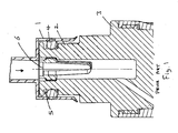
- separate fuel injectors are normally connected to a fuel supply, usually a common fuel supply rail, by means of receiving cups 1 connected to the fuel rail into which an inlet end 2 of the fuel injector 3 is inserted, a fluoropolymer O-ring 4 being provided in a seat 5 around said inlet end 2 of the injector 3 for sealing the gap between the receiving cup 1 and the injector.
- An axial fuel inlet 6 in the inlet end of the injector is thus connected to the fuel rail via the receiving cup 1.
- the fuel rail is usually bolted to the engine, trapping the injectors in their seats between the fuel rail and the engine and thus securing the receiving cups 1 mounted on the fuel rail onto the injectors 3.
- a connecting structure for a high pressure fuel supply of a fuel injector comprising a connection member including an open ended tubular receiving portion communicating with source of high pressure fuel, preferably via a fuel rail and/or fuel supply pipe, the receiving portion being configured to receive a fuel supply inlet of the fuel injector, the fuel supply inlet having an axially arranged fuel inlet port communicating with a spray nozzle of the fuel injector via a selectively operable valve means, an annular sealing ring being locatable around a first peripheral region of the fuel supply inlet at or adjacent a distal end of the fuel supply inlet, the sealing ring being adapted to sealingly abut an inner surface of said receiving portion when the fuel supply inlet is inserted into the receiving portion, a second sealing means being provided around a second peripheral region of the fuel supply inlet axially spaced from said distal end of the fuel supply inlet, the second sealing means cooperating with a further portion of said connection member to define a closed annular space between said first and second peripheral regions
- the first peripheral portion is provided on a first region of the supply inlet and the second peripheral portion is provided on a second region of the supply inlet, the diameter of the second region being greater than the diameter of the first region.
- a fuel return port may be provided in a side region of the fuel supply inlet between said first and second peripheral regions communicating with a fuel return passage of the fuel injector.
- the fuel return port is provided at the juncture between first and second regions of the fuel supply inlet.
- the fuel return port opens into an annular recess between said first and second regions.
- the second sealing means comprises a further annular sealing ring.
- the second sealing means comprises a threaded portion co-operable with a corresponding threaded portion on said second peripheral region of the fuel supply inlet.
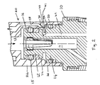
- the fuel injector comprises an injector body 10 having a fuel supply inlet 11 connected to a fuel rail via a tubular receiving cup 20 having an axial fuel supply passageway 22 supplying fuel to an inlet port 11 of the fuel supply inlet.
- the receiving cup 20 comprises a first receiving portion 24 having a first diameter for receiving a distal end portion 12 of the fuel supply inlet and a second or outer receiving portion 26 of a second diameter, greater than said first diameter, for receiving a further or inner portion 14 of the fuel supply inlet.
- a first fluorpolymer O-ring 15 is located in an annular recessed seat 16 around the periphery of the end portion 12 of the fuel supply inlet.
- the first O-ring 15 is dimensioned to provide a fluid tight seal between the first receiving portion 24 and the end portion 12 of the injector to resist leakage of high pressure fuel between the injector body 10 and the receiving cup 20.
- a further fluoropolymer O-ring 30 is provided in an annular recessed seat 32 around the periphery of the inner portion 14 of the fuel supply inlet, such further O-ring 30 being dimensioned to provide a fluid tight seal between the inner portion 14 of the fuel supply inlet and the second receiving portion 26 of the receiving cup 20.
- the first O-ring 15 and the further O-ring 30 define between them an annular space 34.
- a drain port 36 is provided in a side wall of the receiving cup 20, said drain port 36 communicating with said annular space 34 to provide a drain for any fuel that may leak past the first O-ring 15.
- the drain port 36 communicates with a passageway 38 that may be connected to a suitable collection vessel or to a return line to the inlet of the high pressure fuel pump.
- An annular recess 40 is provided in the fuel supply inlet between the end portion 12 and inner portion 14 of the fuel supply inlet.
- a return line 42 of the injector communicates with the annular recess 40 via a port 41 to enable fuel from the return line 42 to pass into the drain port 26 and associated passageway 38 of the receiving cup 20.
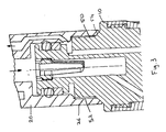
- a second embodiment of the present invention is shown in Fig. 3.
- the further O-ring has been replaced by a threaded portion 50 provided around the periphery of the inner portion 14 of the fuel supply inlet, said threaded portion 50 being cooperable with a corresponding threaded portion 52 on the outer receiving portion 26 of the receiving cup 20 to secure the receiving cup onto the injector body 10, and a flat or conical metal to metal sealing abutment 54 between cooperating faces formed respectively on the receiving cup 20 and the injector body 10.
- Another option is to use a nut pressing the receiving cup onto a metal to metal seal between receiving cup 20 and the injector body 10.
- Such arrangement may be preferred where further securing means are required to hold the receiving cup 20 onto the injector body 10.
Landscapes
- Engineering & Computer Science (AREA)
- Chemical & Material Sciences (AREA)
- Combustion & Propulsion (AREA)
- Mechanical Engineering (AREA)
- General Engineering & Computer Science (AREA)
- Fuel-Injection Apparatus (AREA)
Abstract
Description
- The present invention relates to a connecting structure for a high pressure fuel supply of a fuel injector and in particular to a connecting structure for preventing the leakage of high pressure fuel into the engine compartment.
- As shown in Fig 1, separate fuel injectors are normally connected to a fuel supply, usually a common fuel supply rail, by means of receiving cups 1 connected to the fuel rail into which an
inlet end 2 of thefuel injector 3 is inserted, a fluoropolymer O-ring 4 being provided in a seat 5 around saidinlet end 2 of theinjector 3 for sealing the gap between the receiving cup 1 and the injector. Anaxial fuel inlet 6 in the inlet end of the injector is thus connected to the fuel rail via the receiving cup 1. The fuel rail is usually bolted to the engine, trapping the injectors in their seats between the fuel rail and the engine and thus securing the receiving cups 1 mounted on the fuel rail onto theinjectors 3. - Modern high pressure fuel injection systems typically have a fuel supply pressure of up to 200 bar. Thus any damage to the O-ring can lead to a leakage of fuel past the O-ring and out into the engine compartment due to the large pressure differential on either side of the O-ring.
- Greater attention to avoiding fuel leaks, particularly fuel vapour, is also required to meet ever stricter hydrocarbon emission limits for vehicles.
- According to the present invention there is provided a connecting structure for a high pressure fuel supply of a fuel injector comprising a connection member including an open ended tubular receiving portion communicating with source of high pressure fuel, preferably via a fuel rail and/or fuel supply pipe, the receiving portion being configured to receive a fuel supply inlet of the fuel injector, the fuel supply inlet having an axially arranged fuel inlet port communicating with a spray nozzle of the fuel injector via a selectively operable valve means, an annular sealing ring being locatable around a first peripheral region of the fuel supply inlet at or adjacent a distal end of the fuel supply inlet, the sealing ring being adapted to sealingly abut an inner surface of said receiving portion when the fuel supply inlet is inserted into the receiving portion, a second sealing means being provided around a second peripheral region of the fuel supply inlet axially spaced from said distal end of the fuel supply inlet, the second sealing means cooperating with a further portion of said connection member to define a closed annular space between said first and second peripheral regions, a low pressure return or drain port being provided in a side wall of the receiving portion, whereby any fuel leaking past the annular sealing ring into said closed annular space passes into the drain port.
- Preferably the first peripheral portion is provided on a first region of the supply inlet and the second peripheral portion is provided on a second region of the supply inlet, the diameter of the second region being greater than the diameter of the first region.
- A fuel return port may be provided in a side region of the fuel supply inlet between said first and second peripheral regions communicating with a fuel return passage of the fuel injector. Preferably the fuel return port is provided at the juncture between first and second regions of the fuel supply inlet. Preferably the fuel return port opens into an annular recess between said first and second regions.
- In one embodiment the second sealing means comprises a further annular sealing ring.
- In an alternative embodiment the second sealing means comprises a threaded portion co-operable with a corresponding threaded portion on said second peripheral region of the fuel supply inlet.
- The present invention will now be described, by way of example, with reference to the accompanying drawings, in which:
- Fig 2 is a sectional view of a connecting structure of a fuel injector assembly according to a first embodiment of the present invention, and;
- Fig 3 is a sectional view of a connecting structure of a fuel injector assembly according to a second embodiment of the present invention.
- In the first embodiment of the present invention, as illustrated in Fig 2, the fuel injector comprises an
injector body 10 having a fuel supply inlet 11 connected to a fuel rail via atubular receiving cup 20 having an axialfuel supply passageway 22 supplying fuel to an inlet port 11 of the fuel supply inlet. - The receiving
cup 20 comprises a first receivingportion 24 having a first diameter for receiving adistal end portion 12 of the fuel supply inlet and a second orouter receiving portion 26 of a second diameter, greater than said first diameter, for receiving a further orinner portion 14 of the fuel supply inlet. - A first fluorpolymer O-
ring 15 is located in an annular recessedseat 16 around the periphery of theend portion 12 of the fuel supply inlet. The first O-ring 15 is dimensioned to provide a fluid tight seal between the first receivingportion 24 and theend portion 12 of the injector to resist leakage of high pressure fuel between theinjector body 10 and the receivingcup 20. - A further fluoropolymer O-
ring 30 is provided in an annular recessedseat 32 around the periphery of theinner portion 14 of the fuel supply inlet, such further O-ring 30 being dimensioned to provide a fluid tight seal between theinner portion 14 of the fuel supply inlet and the second receivingportion 26 of the receivingcup 20. The first O-ring 15 and the further O-ring 30 define between them an annular space 34. Adrain port 36 is provided in a side wall of the receivingcup 20, saiddrain port 36 communicating with said annular space 34 to provide a drain for any fuel that may leak past the first O-ring 15. Thedrain port 36 communicates with apassageway 38 that may be connected to a suitable collection vessel or to a return line to the inlet of the high pressure fuel pump. Thus any leakage of fuel from the high pressure side of the first O-ring 15 is prevented from escaping to the receivingcup 20 into the engine compartment. - An
annular recess 40 is provided in the fuel supply inlet between theend portion 12 andinner portion 14 of the fuel supply inlet. Areturn line 42 of the injector communicates with theannular recess 40 via aport 41 to enable fuel from thereturn line 42 to pass into thedrain port 26 and associatedpassageway 38 of the receivingcup 20. - A second embodiment of the present invention is shown in Fig. 3. Most of the components of the second embodiment are identical to those of the first embodiment and thus need not be described in more detail. However, in the second embodiment, the further O-ring has been replaced by a threaded
portion 50 provided around the periphery of theinner portion 14 of the fuel supply inlet, said threadedportion 50 being cooperable with a corresponding threadedportion 52 on the outer receivingportion 26 of the receivingcup 20 to secure the receiving cup onto theinjector body 10, and a flat or conical metal tometal sealing abutment 54 between cooperating faces formed respectively on the receivingcup 20 and theinjector body 10. Another option is to use a nut pressing the receiving cup onto a metal to metal seal between receivingcup 20 and theinjector body 10. - Such arrangement may be preferred where further securing means are required to hold the receiving
cup 20 onto theinjector body 10. - Whilst the above described embodiments show injectors having fuel return lines, it is envisaged that the invention may be equally applicable to fuel injectors which do not include fuel return passageways, the
drain port 36 and associatedpassageway 38 merely being used to collect any fuel or fuel vapour that may escape past the first O-ring 15.
Claims (9)
- A connecting structure for a high pressure fuel supply of a fuel injector comprising a connection member (20) including an open ended tubular receiving portion (24) communicating with source of high pressure fuel and being configured to receive a fuel supply inlet of the fuel injector, the fuel supply inlet having an axially arranged fuel inlet port (11) communicating with a spray nozzle of the fuel injector via a selectively operable valve means, an annular sealing ring (12) being locatable around a first peripheral region (16) of the fuel supply inlet at or adjacent a distal end of the fuel supply inlet, the sealing ring (16) being adapted to sealingly abut an inner surface of said receiving portion (24) when the fuel supply inlet is inserted into the receiving portion, a second sealing means (30,50) being provided around a second peripheral region (32) of the fuel supply inlet axially spaced from said distal end of the fuel supply inlet, the second sealing means (30,50) cooperating with a further portion (26) of said connection member (20) to define a closed annular space (40) between said first and second peripheral regions, a low pressure return or drain port (36) being provided in a side wall of the receiving portion (24), whereby any fuel leaking past the annular sealing ring into said closed annular space passes into the drain port (36).
- A structure as claimed in claim 1, wherein the drain port (36) communicates with a passageway 36 connectable to a collection vessel and/or return feed of a fuel pump.
- A structure as claimed in claim 1 or claim 2, wherein the first peripheral portion (36) is provided on a first region (12) of the fuel supply inlet and the second peripheral portion (32) is provided on a second region (14) of the fuel supply inlet, the diameter of the second region (14) being greater than the diameter of the first region (12).
- A structure as claimed in claim 3, wherein a fuel return port (41) is be provided in a side region of the fuel supply inlet between said first and second regions (12,14) communicating with a fuel return passage (42) of the fuel injector.
- A structure as claimed in claim 4, wherein the fuel return port (41) is provided at the juncture between first and second regions (12,14) of the fuel supply inlet.
- A structure as claimed in claim 5, wherein the fuel return port (41) opens into an annular recess (40) between said first and second regions (12,14).
- A structure as claimed in any preceding claim, wherein the second sealing means comprises a further annular sealing ring (30).
- A structure as claimed in any of claims 1 to 6, wherein the second sealing means comprises a threaded portion (50) co-operable with a corresponding threaded portion (52) on said second peripheral region of the fuel supply inlet.
- A structure as claimed in claim 8, wherein a flat or conical metal to metal sealing abutment (54) is provided between cooperating faces formed respectively on the receiving cup 20 and the injector body 10
Priority Applications (3)
| Application Number | Priority Date | Filing Date | Title |
|---|---|---|---|
| AT05256793T ATE397721T1 (en) | 2005-11-02 | 2005-11-02 | CONNECTING ELEMENT FOR THE HIGH PRESSURE FUEL SUPPLY OF AN INJECTOR |
| EP05256793A EP1783357B1 (en) | 2005-11-02 | 2005-11-02 | Connecting structure for a fuel injector high pressure fuel supply |
| DE602005007362T DE602005007362D1 (en) | 2005-11-02 | 2005-11-02 | Connecting element for the high-pressure fuel supply of an injector |
Applications Claiming Priority (1)
| Application Number | Priority Date | Filing Date | Title |
|---|---|---|---|
| EP05256793A EP1783357B1 (en) | 2005-11-02 | 2005-11-02 | Connecting structure for a fuel injector high pressure fuel supply |
Publications (2)
| Publication Number | Publication Date |
|---|---|
| EP1783357A1 true EP1783357A1 (en) | 2007-05-09 |
| EP1783357B1 EP1783357B1 (en) | 2008-06-04 |
Family
ID=36088457
Family Applications (1)
| Application Number | Title | Priority Date | Filing Date |
|---|---|---|---|
| EP05256793A Expired - Lifetime EP1783357B1 (en) | 2005-11-02 | 2005-11-02 | Connecting structure for a fuel injector high pressure fuel supply |
Country Status (3)
| Country | Link |
|---|---|
| EP (1) | EP1783357B1 (en) |
| AT (1) | ATE397721T1 (en) |
| DE (1) | DE602005007362D1 (en) |
Cited By (2)
| Publication number | Priority date | Publication date | Assignee | Title |
|---|---|---|---|---|
| US11174827B1 (en) | 2020-09-18 | 2021-11-16 | Caterpillar Inc. | Fuel injector with internal radial seal with thin wall counterbore |
| US11248575B1 (en) | 2020-09-18 | 2022-02-15 | Caterpillar Inc. | Fuel injector with internal leak passage to injector drain |
Citations (5)
| Publication number | Priority date | Publication date | Assignee | Title |
|---|---|---|---|---|
| GB2107809A (en) * | 1981-10-16 | 1983-05-05 | Rolls Royce | Fuel pipe seal |
| EP0387504A1 (en) * | 1989-03-11 | 1990-09-19 | Robert Bosch Gmbh | Fuel injection nozzle for internal combustion engines |
| EP1118766A2 (en) * | 2000-01-20 | 2001-07-25 | Siemens Aktiengesellschaft | Fuel injection system for internal combustion engine |
| DE10036137A1 (en) * | 2000-07-25 | 2002-02-07 | Siemens Ag | Procedure for positional fixing of plug-in nipple of fuel overflow pipe in fuel injector entails fitting of nipple before attachment of HP pipe and positionally fixing it by fitting of holder element of HP pipe on HP connector |
| US6431608B1 (en) * | 1999-07-09 | 2002-08-13 | Usui Kokusai Sangyo Kaisha Limited | High pressure fuel injection pipe for diesel engine |
-
2005
- 2005-11-02 DE DE602005007362T patent/DE602005007362D1/en not_active Expired - Lifetime
- 2005-11-02 EP EP05256793A patent/EP1783357B1/en not_active Expired - Lifetime
- 2005-11-02 AT AT05256793T patent/ATE397721T1/en not_active IP Right Cessation
Patent Citations (5)
| Publication number | Priority date | Publication date | Assignee | Title |
|---|---|---|---|---|
| GB2107809A (en) * | 1981-10-16 | 1983-05-05 | Rolls Royce | Fuel pipe seal |
| EP0387504A1 (en) * | 1989-03-11 | 1990-09-19 | Robert Bosch Gmbh | Fuel injection nozzle for internal combustion engines |
| US6431608B1 (en) * | 1999-07-09 | 2002-08-13 | Usui Kokusai Sangyo Kaisha Limited | High pressure fuel injection pipe for diesel engine |
| EP1118766A2 (en) * | 2000-01-20 | 2001-07-25 | Siemens Aktiengesellschaft | Fuel injection system for internal combustion engine |
| DE10036137A1 (en) * | 2000-07-25 | 2002-02-07 | Siemens Ag | Procedure for positional fixing of plug-in nipple of fuel overflow pipe in fuel injector entails fitting of nipple before attachment of HP pipe and positionally fixing it by fitting of holder element of HP pipe on HP connector |
Cited By (2)
| Publication number | Priority date | Publication date | Assignee | Title |
|---|---|---|---|---|
| US11174827B1 (en) | 2020-09-18 | 2021-11-16 | Caterpillar Inc. | Fuel injector with internal radial seal with thin wall counterbore |
| US11248575B1 (en) | 2020-09-18 | 2022-02-15 | Caterpillar Inc. | Fuel injector with internal leak passage to injector drain |
Also Published As
| Publication number | Publication date |
|---|---|
| ATE397721T1 (en) | 2008-06-15 |
| EP1783357B1 (en) | 2008-06-04 |
| DE602005007362D1 (en) | 2008-07-17 |
Similar Documents
| Publication | Publication Date | Title |
|---|---|---|
| US9109557B2 (en) | Connector arrangement for a fluid system | |
| DE102012010939B4 (en) | Suction oil filter unit for gearboxes or combustion engines | |
| CN104564414B (en) | The sealing system of engine | |
| CN101711323A (en) | Pipe joint member for high-pressure fluid | |
| EP2952727B1 (en) | Valve for fuel supply system | |
| WO2018001815A1 (en) | Valve for metering a fluid, connection piece for a valve, and fuel injection system | |
| US6419282B1 (en) | Compliant zero evaporative fuel connection | |
| US20060033062A1 (en) | Valve for controlling fluids | |
| EP1878963A3 (en) | Quick coupling for connecting a pipe and a component, particularly a manifold or a flow control valve, for liquid or gas distribution systems | |
| CN110735739A (en) | Internal combustion engine with a venturi nozzle arranged in a fluid-conducting component | |
| US20090084358A1 (en) | Fuel injector mounting scheme | |
| US20190162143A1 (en) | On-Off Valve For A Fuel Injection System, And High-Pressure Fuel Pump | |
| US8029672B2 (en) | Filter head | |
| US20080265195A1 (en) | Flow connector for a valve | |
| US3513872A (en) | Anti-syphon valve | |
| EP1783357B1 (en) | Connecting structure for a fuel injector high pressure fuel supply | |
| US20220003156A1 (en) | Device for Injecting Water into a Combustion Chamber or into an Intake Tract of an Internal Combustion Engine | |
| RU2658449C1 (en) | Fuel distributor guide end seal design for the direct injection gasoline engine | |
| EP2110543A1 (en) | Safety valve | |
| CN1114715A (en) | Weir control of fuel level in fuel lines to reduce the risk of liquid clogging | |
| US10012192B2 (en) | End seal structure of a fuel rail for a gasoline direct injection engine | |
| DE10032678A1 (en) | Injection device for internal combustion engine, has pipe-shaped connection integrated to the connecting flange for drawing off fuel or fuel gases | |
| JP5518797B2 (en) | Suction valve for fuel supply device of internal combustion engine | |
| JP4885937B2 (en) | Fuel injector assembly | |
| CN104564415B (en) | The sealing system of engine |
Legal Events
| Date | Code | Title | Description |
|---|---|---|---|
| PUAI | Public reference made under article 153(3) epc to a published international application that has entered the european phase |
Free format text: ORIGINAL CODE: 0009012 |
|
| AK | Designated contracting states |
Kind code of ref document: A1 Designated state(s): AT BE BG CH CY CZ DE DK EE ES FI FR GB GR HU IE IS IT LI LT LU LV MC NL PL PT RO SE SI SK TR |
|
| AX | Request for extension of the european patent |
Extension state: AL BA HR MK YU |
|
| 17P | Request for examination filed |
Effective date: 20070403 |
|
| 17Q | First examination report despatched |
Effective date: 20070504 |
|
| GRAP | Despatch of communication of intention to grant a patent |
Free format text: ORIGINAL CODE: EPIDOSNIGR1 |
|
| AKX | Designation fees paid |
Designated state(s): AT BE BG CH CY CZ DE DK EE ES FI FR GB GR HU IE IS IT LI LT LU LV MC NL PL PT RO SE SI SK TR |
|
| GRAS | Grant fee paid |
Free format text: ORIGINAL CODE: EPIDOSNIGR3 |
|
| GRAA | (expected) grant |
Free format text: ORIGINAL CODE: 0009210 |
|
| AK | Designated contracting states |
Kind code of ref document: B1 Designated state(s): AT BE BG CH CY CZ DE DK EE ES FI FR GB GR HU IE IS IT LI LT LU LV MC NL PL PT RO SE SI SK TR |
|
| REG | Reference to a national code |
Ref country code: GB Ref legal event code: FG4D |
|
| REG | Reference to a national code |
Ref country code: CH Ref legal event code: EP |
|
| REF | Corresponds to: |
Ref document number: 602005007362 Country of ref document: DE Date of ref document: 20080717 Kind code of ref document: P |
|
| REG | Reference to a national code |
Ref country code: IE Ref legal event code: FG4D |
|
| PG25 | Lapsed in a contracting state [announced via postgrant information from national office to epo] |
Ref country code: ES Free format text: LAPSE BECAUSE OF FAILURE TO SUBMIT A TRANSLATION OF THE DESCRIPTION OR TO PAY THE FEE WITHIN THE PRESCRIBED TIME-LIMIT Effective date: 20080915 Ref country code: FI Free format text: LAPSE BECAUSE OF FAILURE TO SUBMIT A TRANSLATION OF THE DESCRIPTION OR TO PAY THE FEE WITHIN THE PRESCRIBED TIME-LIMIT Effective date: 20080604 Ref country code: SI Free format text: LAPSE BECAUSE OF FAILURE TO SUBMIT A TRANSLATION OF THE DESCRIPTION OR TO PAY THE FEE WITHIN THE PRESCRIBED TIME-LIMIT Effective date: 20080604 |
|
| PG25 | Lapsed in a contracting state [announced via postgrant information from national office to epo] |
Ref country code: PL Free format text: LAPSE BECAUSE OF FAILURE TO SUBMIT A TRANSLATION OF THE DESCRIPTION OR TO PAY THE FEE WITHIN THE PRESCRIBED TIME-LIMIT Effective date: 20080604 Ref country code: NL Free format text: LAPSE BECAUSE OF FAILURE TO SUBMIT A TRANSLATION OF THE DESCRIPTION OR TO PAY THE FEE WITHIN THE PRESCRIBED TIME-LIMIT Effective date: 20080604 Ref country code: LV Free format text: LAPSE BECAUSE OF FAILURE TO SUBMIT A TRANSLATION OF THE DESCRIPTION OR TO PAY THE FEE WITHIN THE PRESCRIBED TIME-LIMIT Effective date: 20080604 Ref country code: AT Free format text: LAPSE BECAUSE OF FAILURE TO SUBMIT A TRANSLATION OF THE DESCRIPTION OR TO PAY THE FEE WITHIN THE PRESCRIBED TIME-LIMIT Effective date: 20080604 |
|
| NLV1 | Nl: lapsed or annulled due to failure to fulfill the requirements of art. 29p and 29m of the patents act | ||
| PG25 | Lapsed in a contracting state [announced via postgrant information from national office to epo] |
Ref country code: CZ Free format text: LAPSE BECAUSE OF FAILURE TO SUBMIT A TRANSLATION OF THE DESCRIPTION OR TO PAY THE FEE WITHIN THE PRESCRIBED TIME-LIMIT Effective date: 20080604 Ref country code: SE Free format text: LAPSE BECAUSE OF FAILURE TO SUBMIT A TRANSLATION OF THE DESCRIPTION OR TO PAY THE FEE WITHIN THE PRESCRIBED TIME-LIMIT Effective date: 20080904 Ref country code: IS Free format text: LAPSE BECAUSE OF FAILURE TO SUBMIT A TRANSLATION OF THE DESCRIPTION OR TO PAY THE FEE WITHIN THE PRESCRIBED TIME-LIMIT Effective date: 20081004 Ref country code: LT Free format text: LAPSE BECAUSE OF FAILURE TO SUBMIT A TRANSLATION OF THE DESCRIPTION OR TO PAY THE FEE WITHIN THE PRESCRIBED TIME-LIMIT Effective date: 20080604 |
|
| PG25 | Lapsed in a contracting state [announced via postgrant information from national office to epo] |
Ref country code: RO Free format text: LAPSE BECAUSE OF FAILURE TO SUBMIT A TRANSLATION OF THE DESCRIPTION OR TO PAY THE FEE WITHIN THE PRESCRIBED TIME-LIMIT Effective date: 20080604 Ref country code: SK Free format text: LAPSE BECAUSE OF FAILURE TO SUBMIT A TRANSLATION OF THE DESCRIPTION OR TO PAY THE FEE WITHIN THE PRESCRIBED TIME-LIMIT Effective date: 20080604 Ref country code: PT Free format text: LAPSE BECAUSE OF FAILURE TO SUBMIT A TRANSLATION OF THE DESCRIPTION OR TO PAY THE FEE WITHIN THE PRESCRIBED TIME-LIMIT Effective date: 20081104 Ref country code: BE Free format text: LAPSE BECAUSE OF FAILURE TO SUBMIT A TRANSLATION OF THE DESCRIPTION OR TO PAY THE FEE WITHIN THE PRESCRIBED TIME-LIMIT Effective date: 20080604 |
|
| PLBE | No opposition filed within time limit |
Free format text: ORIGINAL CODE: 0009261 |
|
| STAA | Information on the status of an ep patent application or granted ep patent |
Free format text: STATUS: NO OPPOSITION FILED WITHIN TIME LIMIT |
|
| PG25 | Lapsed in a contracting state [announced via postgrant information from national office to epo] |
Ref country code: DK Free format text: LAPSE BECAUSE OF FAILURE TO SUBMIT A TRANSLATION OF THE DESCRIPTION OR TO PAY THE FEE WITHIN THE PRESCRIBED TIME-LIMIT Effective date: 20080604 Ref country code: BG Free format text: LAPSE BECAUSE OF FAILURE TO SUBMIT A TRANSLATION OF THE DESCRIPTION OR TO PAY THE FEE WITHIN THE PRESCRIBED TIME-LIMIT Effective date: 20080904 Ref country code: EE Free format text: LAPSE BECAUSE OF FAILURE TO SUBMIT A TRANSLATION OF THE DESCRIPTION OR TO PAY THE FEE WITHIN THE PRESCRIBED TIME-LIMIT Effective date: 20080604 |
|
| 26N | No opposition filed |
Effective date: 20090305 |
|
| PG25 | Lapsed in a contracting state [announced via postgrant information from national office to epo] |
Ref country code: MC Free format text: LAPSE BECAUSE OF NON-PAYMENT OF DUE FEES Effective date: 20081130 |
|
| PG25 | Lapsed in a contracting state [announced via postgrant information from national office to epo] |
Ref country code: IE Free format text: LAPSE BECAUSE OF NON-PAYMENT OF DUE FEES Effective date: 20081102 |
|
| REG | Reference to a national code |
Ref country code: CH Ref legal event code: PL |
|
| GBPC | Gb: european patent ceased through non-payment of renewal fee |
Effective date: 20091102 |
|
| PG25 | Lapsed in a contracting state [announced via postgrant information from national office to epo] |
Ref country code: LU Free format text: LAPSE BECAUSE OF NON-PAYMENT OF DUE FEES Effective date: 20081102 Ref country code: HU Free format text: LAPSE BECAUSE OF FAILURE TO SUBMIT A TRANSLATION OF THE DESCRIPTION OR TO PAY THE FEE WITHIN THE PRESCRIBED TIME-LIMIT Effective date: 20081205 Ref country code: CY Free format text: LAPSE BECAUSE OF FAILURE TO SUBMIT A TRANSLATION OF THE DESCRIPTION OR TO PAY THE FEE WITHIN THE PRESCRIBED TIME-LIMIT Effective date: 20080604 |
|
| PG25 | Lapsed in a contracting state [announced via postgrant information from national office to epo] |
Ref country code: TR Free format text: LAPSE BECAUSE OF FAILURE TO SUBMIT A TRANSLATION OF THE DESCRIPTION OR TO PAY THE FEE WITHIN THE PRESCRIBED TIME-LIMIT Effective date: 20080604 |
|
| PG25 | Lapsed in a contracting state [announced via postgrant information from national office to epo] |
Ref country code: CH Free format text: LAPSE BECAUSE OF NON-PAYMENT OF DUE FEES Effective date: 20091130 Ref country code: GR Free format text: LAPSE BECAUSE OF FAILURE TO SUBMIT A TRANSLATION OF THE DESCRIPTION OR TO PAY THE FEE WITHIN THE PRESCRIBED TIME-LIMIT Effective date: 20080905 Ref country code: LI Free format text: LAPSE BECAUSE OF NON-PAYMENT OF DUE FEES Effective date: 20091130 |
|
| PG25 | Lapsed in a contracting state [announced via postgrant information from national office to epo] |
Ref country code: GB Free format text: LAPSE BECAUSE OF NON-PAYMENT OF DUE FEES Effective date: 20091102 |
|
| PGFP | Annual fee paid to national office [announced via postgrant information from national office to epo] |
Ref country code: DE Payment date: 20101027 Year of fee payment: 6 |
|
| PGFP | Annual fee paid to national office [announced via postgrant information from national office to epo] |
Ref country code: IT Payment date: 20101112 Year of fee payment: 6 |
|
| PGFP | Annual fee paid to national office [announced via postgrant information from national office to epo] |
Ref country code: FR Payment date: 20111118 Year of fee payment: 7 |
|
| REG | Reference to a national code |
Ref country code: FR Ref legal event code: ST Effective date: 20130731 |
|
| PG25 | Lapsed in a contracting state [announced via postgrant information from national office to epo] |
Ref country code: IT Free format text: LAPSE BECAUSE OF NON-PAYMENT OF DUE FEES Effective date: 20121102 |
|
| REG | Reference to a national code |
Ref country code: DE Ref legal event code: R119 Ref document number: 602005007362 Country of ref document: DE Effective date: 20130601 |
|
| PG25 | Lapsed in a contracting state [announced via postgrant information from national office to epo] |
Ref country code: DE Free format text: LAPSE BECAUSE OF NON-PAYMENT OF DUE FEES Effective date: 20130601 |
|
| PG25 | Lapsed in a contracting state [announced via postgrant information from national office to epo] |
Ref country code: FR Free format text: LAPSE BECAUSE OF NON-PAYMENT OF DUE FEES Effective date: 20121130 |