EP1783342B1 - Methods and apparatus for injecting fluids into a turbine engine - Google Patents
Methods and apparatus for injecting fluids into a turbine engine Download PDFInfo
- Publication number
- EP1783342B1 EP1783342B1 EP06255705.3A EP06255705A EP1783342B1 EP 1783342 B1 EP1783342 B1 EP 1783342B1 EP 06255705 A EP06255705 A EP 06255705A EP 1783342 B1 EP1783342 B1 EP 1783342B1
- Authority
- EP
- European Patent Office
- Prior art keywords
- nozzle tip
- outlets
- fuel
- steam
- nozzle
- Prior art date
- Legal status (The legal status is an assumption and is not a legal conclusion. Google has not performed a legal analysis and makes no representation as to the accuracy of the status listed.)
- Not-in-force
Links
Images



Classifications
-
- F—MECHANICAL ENGINEERING; LIGHTING; HEATING; WEAPONS; BLASTING
- F02—COMBUSTION ENGINES; HOT-GAS OR COMBUSTION-PRODUCT ENGINE PLANTS
- F02C—GAS-TURBINE PLANTS; AIR INTAKES FOR JET-PROPULSION PLANTS; CONTROLLING FUEL SUPPLY IN AIR-BREATHING JET-PROPULSION PLANTS
- F02C3/00—Gas-turbine plants characterised by the use of combustion products as the working fluid
- F02C3/20—Gas-turbine plants characterised by the use of combustion products as the working fluid using a special fuel, oxidant, or dilution fluid to generate the combustion products
- F02C3/30—Adding water, steam or other fluids for influencing combustion, e.g. to obtain cleaner exhaust gases
-
- F—MECHANICAL ENGINEERING; LIGHTING; HEATING; WEAPONS; BLASTING
- F23—COMBUSTION APPARATUS; COMBUSTION PROCESSES
- F23D—BURNERS
- F23D14/00—Burners for combustion of a gas, e.g. of a gas stored under pressure as a liquid
- F23D14/46—Details
- F23D14/48—Nozzles
- F23D14/58—Nozzles characterised by the shape or arrangement of the outlet or outlets from the nozzle, e.g. of annular configuration
-
- F—MECHANICAL ENGINEERING; LIGHTING; HEATING; WEAPONS; BLASTING
- F23—COMBUSTION APPARATUS; COMBUSTION PROCESSES
- F23L—SUPPLYING AIR OR NON-COMBUSTIBLE LIQUIDS OR GASES TO COMBUSTION APPARATUS IN GENERAL ; VALVES OR DAMPERS SPECIALLY ADAPTED FOR CONTROLLING AIR SUPPLY OR DRAUGHT IN COMBUSTION APPARATUS; INDUCING DRAUGHT IN COMBUSTION APPARATUS; TOPS FOR CHIMNEYS OR VENTILATING SHAFTS; TERMINALS FOR FLUES
- F23L7/00—Supplying non-combustible liquids or gases, other than air, to the fire, e.g. oxygen, steam
- F23L7/002—Supplying water
- F23L7/005—Evaporated water; Steam
-
- F—MECHANICAL ENGINEERING; LIGHTING; HEATING; WEAPONS; BLASTING
- F23—COMBUSTION APPARATUS; COMBUSTION PROCESSES
- F23R—GENERATING COMBUSTION PRODUCTS OF HIGH PRESSURE OR HIGH VELOCITY, e.g. GAS-TURBINE COMBUSTION CHAMBERS
- F23R3/00—Continuous combustion chambers using liquid or gaseous fuel
- F23R3/28—Continuous combustion chambers using liquid or gaseous fuel characterised by the fuel supply
- F23R3/34—Feeding into different combustion zones
- F23R3/343—Pilot flames, i.e. fuel nozzles or injectors using only a very small proportion of the total fuel to insure continuous combustion
-
- F—MECHANICAL ENGINEERING; LIGHTING; HEATING; WEAPONS; BLASTING
- F05—INDEXING SCHEMES RELATING TO ENGINES OR PUMPS IN VARIOUS SUBCLASSES OF CLASSES F01-F04
- F05D—INDEXING SCHEME FOR ASPECTS RELATING TO NON-POSITIVE-DISPLACEMENT MACHINES OR ENGINES, GAS-TURBINES OR JET-PROPULSION PLANTS
- F05D2250/00—Geometry
- F05D2250/30—Arrangement of components
- F05D2250/31—Arrangement of components according to the direction of their main axis or their axis of rotation
- F05D2250/314—Arrangement of components according to the direction of their main axis or their axis of rotation the axes being inclined in relation to each other
-
- F—MECHANICAL ENGINEERING; LIGHTING; HEATING; WEAPONS; BLASTING
- F23—COMBUSTION APPARATUS; COMBUSTION PROCESSES
- F23D—BURNERS
- F23D2900/00—Special features of, or arrangements for burners using fluid fuels or solid fuels suspended in a carrier gas
- F23D2900/00014—Pilot burners specially adapted for ignition of main burners in furnaces or gas turbines
Definitions
- This application relates generally to gas turbine engines and, more particularly, to apparatus for injecting fluids into turbine engines.
- Air pollution concerns worldwide have led to stricter emissions standards both domestically and internationally. These same standards have caused turbine engine manufacturers to design more efficient engines, as well as design improved retrofit components that enable engines to operate more efficiently, with improved emissions, and/or with extended useful life and reliability. Moreover, the generally high capital costs associated with the purchase and maintenance of turbine engines, such as revenue losses generated during engine outages, have caused the same engine manufacturers to attempt to design engines that are more reliable and that have extended useful life.
- Controlling the mixture of fluids, i.e. gas and steam, delivered to a gas turbine engine may be critical to the engine's performance.
- gas turbine engines operating with gas and steam do not meet emissions requirements at all operating conditions, and in particular, such engines generally do not satisfy carbon monoxide (CO) emission requirements as well as other known engines.
- CO carbon monoxide
- at least some known dual fuel gas turbine engines utilizing gas and steam generate higher CO emissions than dual fuel gas turbine engines utilizing gas and water. More specifically poor mixing of the gas and steam may cause fuel to remain inboard, leading to higher CO emissions being generated.
- poor mixing may cause the recirculation stability zone within the combustor to be shifted downstream, which may cause the flame to become detached, resulting in the generation of CO emissions.
- EP 1,013,990 A2 relates to a dual fuel nozzle, with figures 3 and 4 thereof disclosing a known nozzle having gaseous fuel outlets 7 and atomizing outlets 10 arranged concentrically about the nozzle tip, with the fuel outlets 7 disposed radially outward from the atomizing outlets.
- the method comprises supplying steam to a nozzle, supplying primary fuel to the nozzle, discharging the steam into a combustor from a plurality of circumferentially-spaced steam outlets defined in a tip of the nozzle, and discharging the primary fuel into the combustor from at least one outlet that is spaced circumferentially between the steam outlets.
- a nozzle tip for a turbine engine fuel nozzle includes an annular body including at least one pilot fuel outlet, a plurality of steam outlets, and a plurality of primary fuel outlets.
- the one (minimum) pilot fuel outlet is configured to discharge pilot fuel from the nozzle tip.
- the plurality of steam outlets are configured to discharge steam from the nozzle tip.
- the plurality of steam outlets are spaced circumferentially about the one (minimum) pilot fuel outlet.
- the plurality of primary fuel outlets are configured to discharge primary fuel from the nozzle tip.
- the plurality of primary fuel outlets are circumferentially aligned with the plurality of steam outlets to discharge primary fuel and steam from said nozzle tip at approximately the same radial position relative to the nozzle center.
- a gas turbine engine in accordance with the appended claims.
- the engine includes a combustor and a fuel nozzle including a nozzle tip.
- the nozzle tip includes an annular body including at least one pilot fuel outlet, a plurality of steam outlets, and a plurality of primary fuel outlets.
- the one (minimum) pilot fuel outlet is configured to discharge pilot fuel to the combustor only during pre-selected engine operations.
- the plurality of primary fuel outlets are circumferentially aligned with respect to the plurality of steam outlets.
- Figure 1 is a schematic illustration of an exemplary gas turbine engine 10 including a low pressure compressor 12, a high pressure compressor 14, and a combustor 16.
- Engine 10 also includes a high pressure turbine 18 and a low pressure turbine 20.
- Compressor 12 and turbine 20 are coupled by a first shaft 22, and compressor 14 and turbine 18 are coupled by a second shaft 21.
- gas turbine engine 10 is an LM2500 engine commercially available from General Electric Aircraft Engines, Cincinnati, Ohio.
- gas turbine engine 10 is a CFM engine commercially available from General Electric Aircraft Engines, Cincinnati, Ohio.
- the highly compressed air is delivered to combustor 16.
- Airflow from combustor 16 is channeled through a turbine nozzle to drive turbines 18 and 20, prior to exiting gas turbine engine 10 through an exhaust nozzle 24.
- gas turbine engines further include fuel nozzles (not shown) which supply fuel to the combustor 16.
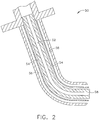
- FIG 2 is a side schematic cross-sectional view of an exemplary embodiment of a fuel nozzle 50 that may be used with a gas turbine engine such as gas turbine engine 10 (shown in Figure 1 ).
- Fuel nozzle 50 includes a pilot fuel circuit 52, a primary fuel circuit 54, and a steam circuit 56.
- Pilot fuel circuit 52 delivers pilot fuel through the center of nozzle 50 to the end 58 of nozzle 50 during start-up and idle operations. End 58 is configured to discharge pilot fuel into the combustor 16 (shown in Figure 1 ) of gas turbine engine 10.
- Primary fuel circuit 54 and steam circuit 56 are positioned radially outward from, and circumferentially around, pilot fuel circuit 52.
- Primary fuel circuit 54 and steam circuit 56 deliver primary fuel and steam, respectively, to combustor 16 through nozzle end 58. More specifically, primary fuel and steam are each discharged through nozzle end 58 into a combustion zone defined downstream from nozzle 50 within combustor 16.
- FIG 3 is a front view of an exemplary fuel nozzle tip 100 that may be used with a fuel nozzle, such as nozzle 50 (shown in Figure 2 ) to inject fluids into a gas turbine engine, such as turbine engine 10 (shown in Figure 1 ).
- Figure 4 is a cross-sectional view of fuel nozzle tip 100.
- fuel nozzle tip 100 includes a plurality of pilot fuel outlets 102, a plurality of primary fuel outlets 104, and a plurality of steam outlets 106. Pilot fuel outlets 102 are spaced circumferentially about, and radially outward from, a center 110 of fuel nozzle tip 100. In one embodiment, pilot fuel outlets 102 are oriented in a "daisy-chain" configuration.
- pilot fuel outlets 102 are oriented obliquely with respect to a centerline 114 extending through nozzle tip 100. As such, pilot fuel discharged from outlets 102 is expelled outward from tip 100 at an oblique angle ⁇ away from centerline 114 and towards steam being discharged from steam outlets 106.
- nozzle tip 100 includes four pilot fuel outlets 102. In alternative embodiments, nozzle tip 100 includes more or less then four pilot fuel outlets 102. As will be appreciated by one of ordinary skill in the art, the number of pilot fuel outlets 102 varies depending on the application of fuel nozzle tip 100.
- Primary fuel outlets 104 and steam outlets 106 are spaced circumferentially around, and radially outward from, pilot fuel outlets 102. More specifically, primary fuel outlets 104 and steam outlets 106 are oriented such that each primary fuel outlet 104 is positioned between an adjacent pair of steam outlets 106. Accordingly, outlets 104 and 106 are circumferentially aligned relative to each other. As such, and as described in more detail below, primary fuel and steam are discharged from fuel nozzle tip 100 at approximately the same radial position 112 relative to nozzle center 110.
- pilot outlets 102 discharge pilot fuel into the combustor during start up or idle operations of the gas turbine engine.
- primary fuel outlets 104 and steam outlets 106 discharge both primary fuel and steam into a combustion zone defined in the combustor of the gas turbine engine.
- Primary fuel and steam are discharged from fuel nozzle tip 100 at approximately the same radial position 112 and at different discharge angles.
- steam outlets 106 are oriented substantially parallel to nozzle centerline 114 such that steam is discharged from tip 100 at a discharge angle that is substantially parallel to centerline 114
- primary fuel outlets 104 are oriented obliquely with respect to steam outlets 106 and centerline 114, such that primary fuel is discharged at a discharge angle ⁇ away from centerline 114.
- mixing of the primary fuel and steam is enhanced as the constituents are discharged from nozzle tip 100.
- the enhanced mixing of primary fuel and steam discharged from fuel nozzle tip 100 facilitates maintaining a more stable flame within a combustion zone defined in the combustor.
- controlling the stability of the flame facilitates reducing the generation of CO emissions within the combustor.
- the above described fuel nozzle tip for a gas turbine engine provides a dual fuel engine capable of meeting emissions standards.
- the fuel nozzle tip includes circumferentially-spaced primary fuel outlets and steam outlets that discharge primary fuel and steam at approximately the same radial position.
- the recirculation zone is pulled to the center of the combustor such that a more stable, lower emissions flame can occur.
- a nozzle tip is provided that facilitates enhanced steam and fuel mixing, and reduced CO emissions in a cost effective and reliable manner.
Landscapes
- Engineering & Computer Science (AREA)
- Chemical & Material Sciences (AREA)
- Combustion & Propulsion (AREA)
- Mechanical Engineering (AREA)
- General Engineering & Computer Science (AREA)
- Engine Equipment That Uses Special Cycles (AREA)
- Spray-Type Burners (AREA)
Description
- This application relates generally to gas turbine engines and, more particularly, to apparatus for injecting fluids into turbine engines.
- Air pollution concerns worldwide have led to stricter emissions standards both domestically and internationally. These same standards have caused turbine engine manufacturers to design more efficient engines, as well as design improved retrofit components that enable engines to operate more efficiently, with improved emissions, and/or with extended useful life and reliability. Moreover, the generally high capital costs associated with the purchase and maintenance of turbine engines, such as revenue losses generated during engine outages, have caused the same engine manufacturers to attempt to design engines that are more reliable and that have extended useful life.
- Controlling the mixture of fluids, i.e. gas and steam, delivered to a gas turbine engine may be critical to the engine's performance. Typically, gas turbine engines operating with gas and steam do not meet emissions requirements at all operating conditions, and in particular, such engines generally do not satisfy carbon monoxide (CO) emission requirements as well as other known engines. For example, at least some known dual fuel gas turbine engines utilizing gas and steam generate higher CO emissions than dual fuel gas turbine engines utilizing gas and water. More specifically poor mixing of the gas and steam may cause fuel to remain inboard, leading to higher CO emissions being generated. Moreover, poor mixing may cause the recirculation stability zone within the combustor to be shifted downstream, which may cause the flame to become detached, resulting in the generation of CO emissions.
-
EP 1,013,990 A2 relates to a dual fuel nozzle, withfigures 3 and4 thereof disclosing a known nozzle having gaseous fuel outlets 7 andatomizing outlets 10 arranged concentrically about the nozzle tip, with the fuel outlets 7 disposed radially outward from the atomizing outlets. - Disclosed herein is a method of operating a gas turbine engine. The method comprises supplying steam to a nozzle, supplying primary fuel to the nozzle, discharging the steam into a combustor from a plurality of circumferentially-spaced steam outlets defined in a tip of the nozzle, and discharging the primary fuel into the combustor from at least one outlet that is spaced circumferentially between the steam outlets.
- In one aspect, a nozzle tip for a turbine engine fuel nozzle is provided in accordance with the appended claims. The tip includes an annular body including at least one pilot fuel outlet, a plurality of steam outlets, and a plurality of primary fuel outlets. The one (minimum) pilot fuel outlet is configured to discharge pilot fuel from the nozzle tip. The plurality of steam outlets are configured to discharge steam from the nozzle tip. The plurality of steam outlets are spaced circumferentially about the one (minimum) pilot fuel outlet. The plurality of primary fuel outlets are configured to discharge primary fuel from the nozzle tip. The plurality of primary fuel outlets are circumferentially aligned with the plurality of steam outlets to discharge primary fuel and steam from said nozzle tip at approximately the same radial position relative to the nozzle center.
- In a further aspect, a gas turbine engine is provided in accordance with the appended claims. The engine includes a combustor and a fuel nozzle including a nozzle tip. The nozzle tip includes an annular body including at least one pilot fuel outlet, a plurality of steam outlets, and a plurality of primary fuel outlets. The one (minimum) pilot fuel outlet is configured to discharge pilot fuel to the combustor only during pre-selected engine operations. The plurality of primary fuel outlets are circumferentially aligned with respect to the plurality of steam outlets.
- Embodiments of the present invention will now be described, by way of example only, with reference to the accompanying drawings, in which:
-
Figure 1 is a schematic illustration of an exemplary gas turbine engine; -
Figure 2 is a side schematic cross-sectional view of an exemplary embodiment of a fuel nozzle that may be used with the gas turbine engine shown inFigure 1 ; -
Figure 3 is a front view of an exemplary fuel nozzle tip that may be used with the engine shown inFigure 1 ; -
Figure 4 is a cross-sectional view of an exemplary fuel nozzle tip shown inFigure 3 . -
Figure 1 is a schematic illustration of an exemplarygas turbine engine 10 including alow pressure compressor 12, ahigh pressure compressor 14, and acombustor 16.Engine 10 also includes ahigh pressure turbine 18 and alow pressure turbine 20.Compressor 12 andturbine 20 are coupled by afirst shaft 22, andcompressor 14 andturbine 18 are coupled by asecond shaft 21. In one embodiment,gas turbine engine 10 is an LM2500 engine commercially available from General Electric Aircraft Engines, Cincinnati, Ohio. In another embodiment,gas turbine engine 10 is a CFM engine commercially available from General Electric Aircraft Engines, Cincinnati, Ohio. - In operation, air flows through
low pressure compressor 12 supplying compressed air fromlow pressure compressor 12 tohigh pressure compressor 14. The highly compressed air is delivered tocombustor 16. Airflow fromcombustor 16 is channeled through a turbine nozzle to driveturbines gas turbine engine 10 through anexhaust nozzle 24. As is known in the art, gas turbine engines further include fuel nozzles (not shown) which supply fuel to thecombustor 16. -
Figure 2 is a side schematic cross-sectional view of an exemplary embodiment of afuel nozzle 50 that may be used with a gas turbine engine such as gas turbine engine 10 (shown inFigure 1 ).Fuel nozzle 50 includes apilot fuel circuit 52, aprimary fuel circuit 54, and asteam circuit 56.Pilot fuel circuit 52 delivers pilot fuel through the center ofnozzle 50 to theend 58 ofnozzle 50 during start-up and idle operations.End 58 is configured to discharge pilot fuel into the combustor 16 (shown inFigure 1 ) ofgas turbine engine 10.Primary fuel circuit 54 andsteam circuit 56 are positioned radially outward from, and circumferentially around,pilot fuel circuit 52.Primary fuel circuit 54 andsteam circuit 56 deliver primary fuel and steam, respectively, tocombustor 16 throughnozzle end 58. More specifically, primary fuel and steam are each discharged throughnozzle end 58 into a combustion zone defined downstream fromnozzle 50 withincombustor 16. -
Figure 3 is a front view of an exemplaryfuel nozzle tip 100 that may be used with a fuel nozzle, such as nozzle 50 (shown inFigure 2 ) to inject fluids into a gas turbine engine, such as turbine engine 10 (shown inFigure 1 ).Figure 4 is a cross-sectional view offuel nozzle tip 100. In the exemplary embodiment,fuel nozzle tip 100 includes a plurality ofpilot fuel outlets 102, a plurality ofprimary fuel outlets 104, and a plurality ofsteam outlets 106.Pilot fuel outlets 102 are spaced circumferentially about, and radially outward from, acenter 110 offuel nozzle tip 100. In one embodiment,pilot fuel outlets 102 are oriented in a "daisy-chain" configuration. - In the exemplary embodiment,
pilot fuel outlets 102 are oriented obliquely with respect to acenterline 114 extending throughnozzle tip 100. As such, pilot fuel discharged fromoutlets 102 is expelled outward fromtip 100 at an oblique angle θ away fromcenterline 114 and towards steam being discharged fromsteam outlets 106. In the exemplary embodiment,nozzle tip 100 includes fourpilot fuel outlets 102. In alternative embodiments,nozzle tip 100 includes more or less then fourpilot fuel outlets 102. As will be appreciated by one of ordinary skill in the art, the number ofpilot fuel outlets 102 varies depending on the application offuel nozzle tip 100. -
Primary fuel outlets 104 andsteam outlets 106 are spaced circumferentially around, and radially outward from,pilot fuel outlets 102. More specifically,primary fuel outlets 104 andsteam outlets 106 are oriented such that eachprimary fuel outlet 104 is positioned between an adjacent pair ofsteam outlets 106. Accordingly,outlets fuel nozzle tip 100 at approximately the same radial position 112 relative tonozzle center 110. - During
operation pilot outlets 102 discharge pilot fuel into the combustor during start up or idle operations of the gas turbine engine. When additional power is demanded,primary fuel outlets 104 andsteam outlets 106 discharge both primary fuel and steam into a combustion zone defined in the combustor of the gas turbine engine. Primary fuel and steam are discharged fromfuel nozzle tip 100 at approximately the same radial position 112 and at different discharge angles. More specifically, in the exemplary embodiment,steam outlets 106 are oriented substantially parallel tonozzle centerline 114 such that steam is discharged fromtip 100 at a discharge angle that is substantially parallel tocenterline 114, andprimary fuel outlets 104 are oriented obliquely with respect to steamoutlets 106 andcenterline 114, such that primary fuel is discharged at a discharge angle β away fromcenterline 114. Because primary fuel and steam are discharged from approximately the same radial position 112 and at different discharge angles, mixing of the primary fuel and steam is enhanced as the constituents are discharged fromnozzle tip 100. Moreover, the enhanced mixing of primary fuel and steam discharged fromfuel nozzle tip 100 facilitates maintaining a more stable flame within a combustion zone defined in the combustor. Generally, controlling the stability of the flame facilitates reducing the generation of CO emissions within the combustor. - As used herein, an element or step recited in the singular and proceeded with the word "a" or "an" should be understood as not excluding plural said elements or steps, unless such exclusion is explicitly recited. Furthermore, references to "one embodiment" of the present invention are not intended to be interpreted as excluding the existence of additional embodiments that also incorporate the recited features.
- The above described fuel nozzle tip for a gas turbine engine provides a dual fuel engine capable of meeting emissions standards. The fuel nozzle tip includes circumferentially-spaced primary fuel outlets and steam outlets that discharge primary fuel and steam at approximately the same radial position. As a result, the recirculation zone is pulled to the center of the combustor such that a more stable, lower emissions flame can occur. As such, a nozzle tip is provided that facilitates enhanced steam and fuel mixing, and reduced CO emissions in a cost effective and reliable manner.
- Although the methods and systems described herein are described in the context of supplying fuel to a gas turbine engine, it is understood that the fuel nozzle tip methods and systems described herein are not limited to gas turbine engines. Likewise, the fuel nozzle tip components illustrated are not limited to the specific embodiments described herein, but rather, components of the fuel nozzle tip can be utilized independently and separately from other components described herein.
- While the invention has been described in terms of various specific embodiments, those skilled in the art will recognize that the invention can be practiced with modification within the scope of the claims.
Claims (8)
- A nozzle tip (100) for a turbine engine fuel nozzle (50), said tip comprising an annular body comprising:at least one pilot fuel outlet (102) configured to discharge pilot fuel from said nozzle tip;a plurality of steam outlets (106) configured to discharge steam from said nozzle tip, said plurality of steam outlets spaced circumferentially about said at least one pilot fuel outlet; anda plurality of primary fuel outlets (104) configured to discharge primary fuel from said nozzle tip, characterized in thatsaid plurality of primary fuel outlets are circumferentially aligned with said plurality of steam outlets to discharge primary fuel and steam from said nozzle tip at approximately the same radial position (112) relative to a nozzle center (110),wherein each of said plurality of primary fuel outlets (104) is positioned between a circumferentially-adjacent pair of said plurality of steam outlets (106).
- A nozzle tip (100) in accordance with Claim 1, wherein said nozzle tip further comprises a centerline (114) extending there through, said at least one pilot fuel outlet (102) is spaced radially outward from said centerline.
- A nozzle tip (100) in accordance with Claim 1, wherein said at least one pilot fuel outlet (102) is positioned a first radial distance from a center (110) of said nozzle tip, said plurality of steam outlets (106) and said plurality of primary fuel outlets (104) are each positioned a second radial distance from said nozzle tip center.
- A nozzle tip (100) in accordance with Claim 3, wherein said first radial distance is shorter than said second radial distance.
- A nozzle tip (100) in accordance with Claim 1, wherein said at least one pilot fuel outlet (102) is configured to discharge pilot fuel from said nozzle tip at a discharge angle that is oblique with respect to a centerline (114) extending through said nozzle tip.
- A nozzle tip (100) in accordance with Claim 5, wherein at least one of said plurality of steam outlets (106) and said plurality of primary fuel outlets (104) are configured to discharge one of steam and primary fuel at a discharge angle that is substantially parallel to said centerline (114) extending through said nozzle tip.
- A gas turbine engine (10) comprising:a combustor (16); anda fuel nozzle (50) comprising a nozzle tip (100) in accordance with any of the preceding claims, said at least one pilot fuel outlet configured to discharge pilot fuel to said combustor only during pre-selected engine operations.
- A gas turbine engine (10) in accordance with Claim 7, wherein each of said plurality of primary fuel outlets (104) is positioned between a circumferentially-spaced adjacent pair of steam outlets (106).
Applications Claiming Priority (1)
| Application Number | Priority Date | Filing Date | Title |
|---|---|---|---|
| US11/268,183 US7665308B2 (en) | 2005-11-07 | 2005-11-07 | Methods and apparatus for injecting fluids into a turbine engine |
Publications (3)
| Publication Number | Publication Date |
|---|---|
| EP1783342A2 EP1783342A2 (en) | 2007-05-09 |
| EP1783342A3 EP1783342A3 (en) | 2014-01-08 |
| EP1783342B1 true EP1783342B1 (en) | 2017-04-12 |
Family
ID=37800900
Family Applications (1)
| Application Number | Title | Priority Date | Filing Date |
|---|---|---|---|
| EP06255705.3A Not-in-force EP1783342B1 (en) | 2005-11-07 | 2006-11-06 | Methods and apparatus for injecting fluids into a turbine engine |
Country Status (4)
| Country | Link |
|---|---|
| US (1) | US7665308B2 (en) |
| EP (1) | EP1783342B1 (en) |
| JP (1) | JP5013817B2 (en) |
| CA (1) | CA2566789C (en) |
Families Citing this family (4)
| Publication number | Priority date | Publication date | Assignee | Title |
|---|---|---|---|---|
| US7451602B2 (en) * | 2005-11-07 | 2008-11-18 | General Electric Company | Methods and apparatus for injecting fluids into turbine engines |
| US7520134B2 (en) * | 2006-09-29 | 2009-04-21 | General Electric Company | Methods and apparatus for injecting fluids into a turbine engine |
| US11506388B1 (en) | 2021-05-07 | 2022-11-22 | General Electric Company | Furcating pilot pre-mixer for main mini-mixer array in a gas turbine engine |
| US12637975B2 (en) | 2024-02-01 | 2026-05-26 | General Electric Company | Cooling fluid control system and methods of operating a cooling fluid system for a turbine engine |
Family Cites Families (19)
| Publication number | Priority date | Publication date | Assignee | Title |
|---|---|---|---|---|
| US1589704A (en) * | 1924-09-15 | 1926-06-22 | James A Kenworthy | Oil burner |
| JP2955093B2 (en) * | 1991-12-25 | 1999-10-04 | 三菱重工業株式会社 | Gas turbine combustor fuel nozzle |
| JP3174634B2 (en) * | 1992-08-11 | 2001-06-11 | 三菱重工業株式会社 | Gas turbine fuel injection system |
| IT1263683B (en) * | 1992-08-21 | 1996-08-27 | Westinghouse Electric Corp | NOZZLE COMPLEX FOR FUEL FOR A GAS TURBINE |
| JP3457907B2 (en) * | 1998-12-24 | 2003-10-20 | 三菱重工業株式会社 | Dual fuel nozzle |
| JP2001041454A (en) * | 1999-07-27 | 2001-02-13 | Ishikawajima Harima Heavy Ind Co Ltd | Non-combined fuel injection nozzle |
| US6983605B1 (en) * | 2000-04-07 | 2006-01-10 | General Electric Company | Methods and apparatus for reducing gas turbine engine emissions |
| US6370862B1 (en) * | 2000-08-11 | 2002-04-16 | Cheng Power Systems, Inc. | Steam injection nozzle design of gas turbine combustion liners for enhancing power output and efficiency |
| GB0211350D0 (en) * | 2002-05-16 | 2002-06-26 | Rolls Royce Plc | A gas turbine engine |
| US6715295B2 (en) * | 2002-05-22 | 2004-04-06 | Siemens Westinghouse Power Corporation | Gas turbine pilot burner water injection and method of operation |
| US6865890B2 (en) * | 2002-06-07 | 2005-03-15 | Ronald Steven Walker | Software system for verification of gas fuel flow |
| US7028485B1 (en) * | 2002-10-02 | 2006-04-18 | Mee Industries, Inc. | Surge prevention for compressor inlet air fogging |
| US7047748B2 (en) * | 2002-12-02 | 2006-05-23 | Bert Zauderer | Injection methods to reduce nitrogen oxides emission from gas turbines combustors |
| US6935116B2 (en) * | 2003-04-28 | 2005-08-30 | Power Systems Mfg., Llc | Flamesheet combustor |
| US7104069B2 (en) * | 2003-06-25 | 2006-09-12 | Power Systems Mfg., Llc | Apparatus and method for improving combustion stability |
| US6938425B2 (en) * | 2003-08-11 | 2005-09-06 | Siemens Westinghouse Power Corporation | System and method for controlling water injection in a turbine engine |
| US7200997B2 (en) * | 2004-02-09 | 2007-04-10 | Siemens Power Generation, Inc. | Water augmented regeneration (WAR) turbine system and cycle |
| US7178339B2 (en) * | 2004-04-07 | 2007-02-20 | Lockheed Martin Corporation | Closed-loop cooling system for a hydrogen/oxygen based combustor |
| US7520134B2 (en) * | 2006-09-29 | 2009-04-21 | General Electric Company | Methods and apparatus for injecting fluids into a turbine engine |
-
2005
- 2005-11-07 US US11/268,183 patent/US7665308B2/en active Active
-
2006
- 2006-11-02 CA CA2566789A patent/CA2566789C/en not_active Expired - Fee Related
- 2006-11-06 JP JP2006300106A patent/JP5013817B2/en not_active Expired - Fee Related
- 2006-11-06 EP EP06255705.3A patent/EP1783342B1/en not_active Not-in-force
Non-Patent Citations (1)
| Title |
|---|
| None * |
Also Published As
| Publication number | Publication date |
|---|---|
| JP2007132653A (en) | 2007-05-31 |
| JP5013817B2 (en) | 2012-08-29 |
| EP1783342A3 (en) | 2014-01-08 |
| US20070101726A1 (en) | 2007-05-10 |
| CA2566789A1 (en) | 2007-05-07 |
| US7665308B2 (en) | 2010-02-23 |
| CA2566789C (en) | 2013-06-11 |
| EP1783342A2 (en) | 2007-05-09 |
Similar Documents
| Publication | Publication Date | Title |
|---|---|---|
| US7520134B2 (en) | Methods and apparatus for injecting fluids into a turbine engine | |
| US12085281B2 (en) | Fuel nozzle and swirler | |
| US7757492B2 (en) | Method and apparatus to facilitate cooling turbine engines | |
| EP1887191B1 (en) | Cooling of a shroud hanger assembly of a gas turbine engine | |
| JP5091869B2 (en) | Improved airflow distribution for low emission combustors. | |
| EP2570728B1 (en) | Fuel injector | |
| US11725819B2 (en) | Gas turbine fuel nozzle having a fuel passage within a swirler | |
| JP2008190855A (en) | Center body for mixer assembly of gas turbine engine combustor | |
| EP2481985B1 (en) | Fuel injector assembly | |
| JP2013250046A (en) | Fuel injection assembly for use in turbine engine and method of assembling the same | |
| US20230213194A1 (en) | Turbine engine fuel premixer | |
| CA2516753A1 (en) | Methods and apparatus for reducing gas turbine engine emissions | |
| US7665308B2 (en) | Methods and apparatus for injecting fluids into a turbine engine | |
| EP1783429B1 (en) | Apparatus for injecting fluids into turbines engines | |
| JP5555724B2 (en) | Power generation system | |
| US20140150452A1 (en) | Transition piece for a gas turbine system | |
| EP4202301B1 (en) | Combustor with dilution openings | |
| EP4678902A1 (en) | Method of supplying a fuel to a combustor for a turbine engine | |
| CA2596789C (en) | Pilot mixer for mixer assembly of a gas turbine engine combustor having a primary fuel injector and a plurality of secondary fuel injection ports |
Legal Events
| Date | Code | Title | Description |
|---|---|---|---|
| PUAI | Public reference made under article 153(3) epc to a published international application that has entered the european phase |
Free format text: ORIGINAL CODE: 0009012 |
|
| AK | Designated contracting states |
Kind code of ref document: A2 Designated state(s): AT BE BG CH CY CZ DE DK EE ES FI FR GB GR HU IE IS IT LI LT LU LV MC NL PL PT RO SE SI SK TR |
|
| AX | Request for extension of the european patent |
Extension state: AL BA HR MK YU |
|
| PUAL | Search report despatched |
Free format text: ORIGINAL CODE: 0009013 |
|
| AK | Designated contracting states |
Kind code of ref document: A3 Designated state(s): AT BE BG CH CY CZ DE DK EE ES FI FR GB GR HU IE IS IT LI LT LU LV MC NL PL PT RO SE SI SK TR |
|
| AX | Request for extension of the european patent |
Extension state: AL BA HR MK RS |
|
| RIC1 | Information provided on ipc code assigned before grant |
Ipc: F23L 7/00 20060101ALI20131129BHEP Ipc: F23D 14/58 20060101ALI20131129BHEP Ipc: F23R 3/34 20060101ALI20131129BHEP Ipc: F23R 3/28 20060101ALI20131129BHEP Ipc: F02C 3/30 20060101AFI20131129BHEP |
|
| 17P | Request for examination filed |
Effective date: 20140708 |
|
| RBV | Designated contracting states (corrected) |
Designated state(s): AT BE BG CH CY CZ DE DK EE ES FI FR GB GR HU IE IS IT LI LT LU LV MC NL PL PT RO SE SI SK TR |
|
| AKX | Designation fees paid |
Designated state(s): DE FR GB |
|
| 17Q | First examination report despatched |
Effective date: 20150908 |
|
| GRAP | Despatch of communication of intention to grant a patent |
Free format text: ORIGINAL CODE: EPIDOSNIGR1 |
|
| INTG | Intention to grant announced |
Effective date: 20161213 |
|
| GRAS | Grant fee paid |
Free format text: ORIGINAL CODE: EPIDOSNIGR3 |
|
| GRAA | (expected) grant |
Free format text: ORIGINAL CODE: 0009210 |
|
| AK | Designated contracting states |
Kind code of ref document: B1 Designated state(s): DE FR GB |
|
| REG | Reference to a national code |
Ref country code: GB Ref legal event code: FG4D |
|
| REG | Reference to a national code |
Ref country code: DE Ref legal event code: R096 Ref document number: 602006052226 Country of ref document: DE |
|
| REG | Reference to a national code |
Ref country code: DE Ref legal event code: R097 Ref document number: 602006052226 Country of ref document: DE |
|
| PLBE | No opposition filed within time limit |
Free format text: ORIGINAL CODE: 0009261 |
|
| STAA | Information on the status of an ep patent application or granted ep patent |
Free format text: STATUS: NO OPPOSITION FILED WITHIN TIME LIMIT |
|
| 26N | No opposition filed |
Effective date: 20180115 |
|
| REG | Reference to a national code |
Ref country code: DE Ref legal event code: R119 Ref document number: 602006052226 Country of ref document: DE |
|
| GBPC | Gb: european patent ceased through non-payment of renewal fee |
Effective date: 20171106 |
|
| REG | Reference to a national code |
Ref country code: FR Ref legal event code: ST Effective date: 20180731 |
|
| PG25 | Lapsed in a contracting state [announced via postgrant information from national office to epo] |
Ref country code: FR Free format text: LAPSE BECAUSE OF NON-PAYMENT OF DUE FEES Effective date: 20171130 Ref country code: DE Free format text: LAPSE BECAUSE OF NON-PAYMENT OF DUE FEES Effective date: 20180602 |
|
| PG25 | Lapsed in a contracting state [announced via postgrant information from national office to epo] |
Ref country code: GB Free format text: LAPSE BECAUSE OF NON-PAYMENT OF DUE FEES Effective date: 20171106 |