EP1783336A1 - Vehicle exhaust after treatment system - Google Patents
Vehicle exhaust after treatment system Download PDFInfo
- Publication number
- EP1783336A1 EP1783336A1 EP06076922A EP06076922A EP1783336A1 EP 1783336 A1 EP1783336 A1 EP 1783336A1 EP 06076922 A EP06076922 A EP 06076922A EP 06076922 A EP06076922 A EP 06076922A EP 1783336 A1 EP1783336 A1 EP 1783336A1
- Authority
- EP
- European Patent Office
- Prior art keywords
- exhaust
- treatment system
- adsorber
- vehicle exhaust
- volume
- Prior art date
- Legal status (The legal status is an assumption and is not a legal conclusion. Google has not performed a legal analysis and makes no representation as to the accuracy of the status listed.)
- Withdrawn
Links
Images

Classifications
-
- F—MECHANICAL ENGINEERING; LIGHTING; HEATING; WEAPONS; BLASTING
- F01—MACHINES OR ENGINES IN GENERAL; ENGINE PLANTS IN GENERAL; STEAM ENGINES
- F01N—GAS-FLOW SILENCERS OR EXHAUST APPARATUS FOR MACHINES OR ENGINES IN GENERAL; GAS-FLOW SILENCERS OR EXHAUST APPARATUS FOR INTERNAL COMBUSTION ENGINES
- F01N3/00—Exhaust or silencing apparatus having means for purifying, rendering innocuous, or otherwise treating exhaust
- F01N3/02—Exhaust or silencing apparatus having means for purifying, rendering innocuous, or otherwise treating exhaust for cooling, or for removing solid constituents of, exhaust
- F01N3/021—Exhaust or silencing apparatus having means for purifying, rendering innocuous, or otherwise treating exhaust for cooling, or for removing solid constituents of, exhaust by means of filters
- F01N3/023—Exhaust or silencing apparatus having means for purifying, rendering innocuous, or otherwise treating exhaust for cooling, or for removing solid constituents of, exhaust by means of filters using means for regenerating the filters, e.g. by burning trapped particles
- F01N3/025—Exhaust or silencing apparatus having means for purifying, rendering innocuous, or otherwise treating exhaust for cooling, or for removing solid constituents of, exhaust by means of filters using means for regenerating the filters, e.g. by burning trapped particles using fuel burner or by adding fuel to exhaust
-
- F—MECHANICAL ENGINEERING; LIGHTING; HEATING; WEAPONS; BLASTING
- F01—MACHINES OR ENGINES IN GENERAL; ENGINE PLANTS IN GENERAL; STEAM ENGINES
- F01N—GAS-FLOW SILENCERS OR EXHAUST APPARATUS FOR MACHINES OR ENGINES IN GENERAL; GAS-FLOW SILENCERS OR EXHAUST APPARATUS FOR INTERNAL COMBUSTION ENGINES
- F01N13/00—Exhaust or silencing apparatus characterised by constructional features ; Exhaust or silencing apparatus, or parts thereof, having pertinent characteristics not provided for in, or of interest apart from, groups F01N1/00 - F01N5/00, F01N9/00, F01N11/00
- F01N13/009—Exhaust or silencing apparatus characterised by constructional features ; Exhaust or silencing apparatus, or parts thereof, having pertinent characteristics not provided for in, or of interest apart from, groups F01N1/00 - F01N5/00, F01N9/00, F01N11/00 having two or more separate purifying devices arranged in series
- F01N13/0093—Exhaust or silencing apparatus characterised by constructional features ; Exhaust or silencing apparatus, or parts thereof, having pertinent characteristics not provided for in, or of interest apart from, groups F01N1/00 - F01N5/00, F01N9/00, F01N11/00 having two or more separate purifying devices arranged in series the purifying devices are of the same type
-
- F—MECHANICAL ENGINEERING; LIGHTING; HEATING; WEAPONS; BLASTING
- F01—MACHINES OR ENGINES IN GENERAL; ENGINE PLANTS IN GENERAL; STEAM ENGINES
- F01N—GAS-FLOW SILENCERS OR EXHAUST APPARATUS FOR MACHINES OR ENGINES IN GENERAL; GAS-FLOW SILENCERS OR EXHAUST APPARATUS FOR INTERNAL COMBUSTION ENGINES
- F01N13/00—Exhaust or silencing apparatus characterised by constructional features ; Exhaust or silencing apparatus, or parts thereof, having pertinent characteristics not provided for in, or of interest apart from, groups F01N1/00 - F01N5/00, F01N9/00, F01N11/00
- F01N13/009—Exhaust or silencing apparatus characterised by constructional features ; Exhaust or silencing apparatus, or parts thereof, having pertinent characteristics not provided for in, or of interest apart from, groups F01N1/00 - F01N5/00, F01N9/00, F01N11/00 having two or more separate purifying devices arranged in series
- F01N13/0097—Exhaust or silencing apparatus characterised by constructional features ; Exhaust or silencing apparatus, or parts thereof, having pertinent characteristics not provided for in, or of interest apart from, groups F01N1/00 - F01N5/00, F01N9/00, F01N11/00 having two or more separate purifying devices arranged in series the purifying devices are arranged in a single housing
-
- F—MECHANICAL ENGINEERING; LIGHTING; HEATING; WEAPONS; BLASTING
- F01—MACHINES OR ENGINES IN GENERAL; ENGINE PLANTS IN GENERAL; STEAM ENGINES
- F01N—GAS-FLOW SILENCERS OR EXHAUST APPARATUS FOR MACHINES OR ENGINES IN GENERAL; GAS-FLOW SILENCERS OR EXHAUST APPARATUS FOR INTERNAL COMBUSTION ENGINES
- F01N3/00—Exhaust or silencing apparatus having means for purifying, rendering innocuous, or otherwise treating exhaust
- F01N3/08—Exhaust or silencing apparatus having means for purifying, rendering innocuous, or otherwise treating exhaust for rendering innocuous
- F01N3/0807—Exhaust or silencing apparatus having means for purifying, rendering innocuous, or otherwise treating exhaust for rendering innocuous by using absorbents or adsorbents
- F01N3/0814—Exhaust or silencing apparatus having means for purifying, rendering innocuous, or otherwise treating exhaust for rendering innocuous by using absorbents or adsorbents combined with catalytic converters, e.g. NOx absorption/storage reduction catalysts
-
- F—MECHANICAL ENGINEERING; LIGHTING; HEATING; WEAPONS; BLASTING
- F01—MACHINES OR ENGINES IN GENERAL; ENGINE PLANTS IN GENERAL; STEAM ENGINES
- F01N—GAS-FLOW SILENCERS OR EXHAUST APPARATUS FOR MACHINES OR ENGINES IN GENERAL; GAS-FLOW SILENCERS OR EXHAUST APPARATUS FOR INTERNAL COMBUSTION ENGINES
- F01N3/00—Exhaust or silencing apparatus having means for purifying, rendering innocuous, or otherwise treating exhaust
- F01N3/08—Exhaust or silencing apparatus having means for purifying, rendering innocuous, or otherwise treating exhaust for rendering innocuous
- F01N3/0807—Exhaust or silencing apparatus having means for purifying, rendering innocuous, or otherwise treating exhaust for rendering innocuous by using absorbents or adsorbents
- F01N3/0828—Exhaust or silencing apparatus having means for purifying, rendering innocuous, or otherwise treating exhaust for rendering innocuous by using absorbents or adsorbents characterised by the absorbed or adsorbed substances
- F01N3/0842—Nitrogen oxides
-
- F—MECHANICAL ENGINEERING; LIGHTING; HEATING; WEAPONS; BLASTING
- F01—MACHINES OR ENGINES IN GENERAL; ENGINE PLANTS IN GENERAL; STEAM ENGINES
- F01N—GAS-FLOW SILENCERS OR EXHAUST APPARATUS FOR MACHINES OR ENGINES IN GENERAL; GAS-FLOW SILENCERS OR EXHAUST APPARATUS FOR INTERNAL COMBUSTION ENGINES
- F01N3/00—Exhaust or silencing apparatus having means for purifying, rendering innocuous, or otherwise treating exhaust
- F01N3/08—Exhaust or silencing apparatus having means for purifying, rendering innocuous, or otherwise treating exhaust for rendering innocuous
- F01N3/10—Exhaust or silencing apparatus having means for purifying, rendering innocuous, or otherwise treating exhaust for rendering innocuous by thermal or catalytic conversion of noxious components of exhaust
- F01N3/18—Exhaust or silencing apparatus having means for purifying, rendering innocuous, or otherwise treating exhaust for rendering innocuous by thermal or catalytic conversion of noxious components of exhaust characterised by methods of operation; Control
- F01N3/20—Exhaust or silencing apparatus having means for purifying, rendering innocuous, or otherwise treating exhaust for rendering innocuous by thermal or catalytic conversion of noxious components of exhaust characterised by methods of operation; Control specially adapted for catalytic conversion ; Methods of operation or control of catalytic converters
- F01N3/2006—Periodically heating or cooling catalytic reactors, e.g. at cold starting or overheating
-
- F—MECHANICAL ENGINEERING; LIGHTING; HEATING; WEAPONS; BLASTING
- F01—MACHINES OR ENGINES IN GENERAL; ENGINE PLANTS IN GENERAL; STEAM ENGINES
- F01N—GAS-FLOW SILENCERS OR EXHAUST APPARATUS FOR MACHINES OR ENGINES IN GENERAL; GAS-FLOW SILENCERS OR EXHAUST APPARATUS FOR INTERNAL COMBUSTION ENGINES
- F01N2240/00—Combination or association of two or more different exhaust treating devices, or of at least one such device with an auxiliary device, not covered by indexing codes F01N2230/00 or F01N2250/00, one of the devices being
- F01N2240/30—Combination or association of two or more different exhaust treating devices, or of at least one such device with an auxiliary device, not covered by indexing codes F01N2230/00 or F01N2250/00, one of the devices being a fuel reformer
-
- Y—GENERAL TAGGING OF NEW TECHNOLOGICAL DEVELOPMENTS; GENERAL TAGGING OF CROSS-SECTIONAL TECHNOLOGIES SPANNING OVER SEVERAL SECTIONS OF THE IPC; TECHNICAL SUBJECTS COVERED BY FORMER USPC CROSS-REFERENCE ART COLLECTIONS [XRACs] AND DIGESTS
- Y02—TECHNOLOGIES OR APPLICATIONS FOR MITIGATION OR ADAPTATION AGAINST CLIMATE CHANGE
- Y02A—TECHNOLOGIES FOR ADAPTATION TO CLIMATE CHANGE
- Y02A50/00—TECHNOLOGIES FOR ADAPTATION TO CLIMATE CHANGE in human health protection, e.g. against extreme weather
- Y02A50/20—Air quality improvement or preservation, e.g. vehicle emission control or emission reduction by using catalytic converters
-
- Y—GENERAL TAGGING OF NEW TECHNOLOGICAL DEVELOPMENTS; GENERAL TAGGING OF CROSS-SECTIONAL TECHNOLOGIES SPANNING OVER SEVERAL SECTIONS OF THE IPC; TECHNICAL SUBJECTS COVERED BY FORMER USPC CROSS-REFERENCE ART COLLECTIONS [XRACs] AND DIGESTS
- Y02—TECHNOLOGIES OR APPLICATIONS FOR MITIGATION OR ADAPTATION AGAINST CLIMATE CHANGE
- Y02T—CLIMATE CHANGE MITIGATION TECHNOLOGIES RELATED TO TRANSPORTATION
- Y02T10/00—Road transport of goods or passengers
- Y02T10/10—Internal combustion engine [ICE] based vehicles
- Y02T10/12—Improving ICE efficiencies
Definitions
- the present invention relates to a vehicle exhaust after treatment system, more particularly, to an after treatment system architecture for reducing cold start emissions.
- the quantities of pollutants generated by incomplete combustion varies with operating conditions of the engine but are influenced predominantly by the air-to-fuel ratio in the combustion cylinder.
- Conditions conducive to reducing carbon monoxide and unburned hydrocarbons i.e., a fuel mixture just lean of stoichiometric and high combustion temperatures, cause an increased formation of NO x
- conditions conducive to reducing the formation of NO x i.e., rich fuel mixture and low combustion temperatures, cause an increase in carbon monoxide and unburned hydrocarbons in the exhaust gases.
- significant amounts of CO, HC and NO x are emitted from the engine.
- the catalyst can be heated to light-off temperature, using, for example, exhaust heating, injection of reformate, and heating of reformate using an in-exhaust burner.
- Reformates are hydrogen-enriched fuels that can be produced from a variety of sources, including gasoline, diesel, and other liquid or gaseous fuels.
- On-board reformers for producing hydrogen-enriched reformate fuels are described in, for example, U.S. Patent Nos. 6,655,130 and 6,832,473 and U.S. Patent Appl. Publ. Nos. 2004/0146458 and 2005/0022450 , the disclosures of which are incorporated herein by reference.
- the vehicle exhaust after treatment system of the present invention which is particularly suitable for use with a diesel engine, includes an exhaust catalyst that comprises a small volume NO x adsorber coupled with a small volume oxidation catalyst.
- This configuration of the exhaust catalyst enables it to be quickly heated to the temperature where NO x storage begins to occur, typically above 150°C, and then to light-off temperature, where the catalyst is able to convert the stored NO x to N 2 . This rapid storage and light-off also allows the amount of included precious metal to be reduced.
- the present invention is directed to a vehicle exhaust after treatment system for controlling emissions from an engine.
- the system comprises, in serial order: an exhaust outlet from the engine, an exhaust catalyst assembly that is in fluid communication with the exhaust outlet and comprises a first NO x adsorber coupled with a downstream oxidation catalyst, and a second NO x adsorber that is downstream from and in fluid communication with the oxidation catalyst of the exhaust catalyst assembly.
- FIGS. 1-6 indicate the direction of gas flow in the exhaust after treatment system of the present invention.
- a first embodiment 10 of the invention includes an exhaust outlet 11 connected to an exhaust catalyst assembly 12 comprising a first NO x component 12a coupled with a downstream oxidation catalyst 12b.
- An exhaust conduit 13 connects oxidation catalyst 12b with a second NO x adsorber 14, which preferably is an underfloor adsorber.
- System 10 preferably further includes a particulate filter 15 connected to second NO x adsorber 14 by exhaust conduit 13. The volume of particulate filter 15 preferably is greater than that of second NO x adsorber 14.
- Exhaust catalyst assembly 12 whose volume preferably is smaller than that of second NO x adsorber 14, can be rapidly brought to operating temperature by means of a heat source 16, preferably reformate fuel produced by an on-board reformer.
- the reformate fuel can be supplied to catalyst assembly 12 via a reformer conduit 17 connected to exhaust outlet 11.
- the volume of exhaust catalyst assembly 12 preferably is about 1.5 liters to about 3 liters, each of first NO x adsorber 12a and oxidation catalyst having a volume preferably of about 0.75 liter to about 1.5 liters.
- the volume of second NO x adsorber 14 preferably is about 5 liters to about 8 liters, and the volume of particulate filter 15 preferably is about 8 liters to about 13 liters.
- a second embodiment 20 of the invention is similar to that of system 10 schematically depicted in FIG. 1, except that a burner 21 is included in exhaust outlet 11 to increase the temperature of the reformate fuel delivered from heat source 16 and to oxidize any HC and CO that may be present, thereby preventing passage of these gases to downstream catalysts that have not yet reached their operating temperatures.
- a third embodiment 30 of the invention is similar to that of system 20 schematically depicted in FIG. 2, except that a second burner 31 is installed in exhaust conduit 13 downstream from second NO x adsorber 14. Burner 31 assists in the regeneration of particulate filter 15 by promoting the combustion of particles collected on the filter surfaces.
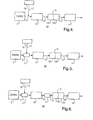
- a fourth embodiment 40 of the invention is similar to that of system 10 schematically depicted in FIG. 1, except that particulate filter 15 is connected to exhaust outlet 11 and is disposed upstream from catalyst assembly 12 comprising first NO x component 12a coupled with downstream oxidation catalyst 12b.
- exhaust conduit 13 connects oxidation catalyst 12b with second NO x adsorber 14, which preferably is an underfloor adsorber.
- System 40 further preferably includes heat source 16, preferably reformate fuel produced by an on-board reformer.
- the reformate fuel can be supplied to exhaust outlet 11 via reformer conduit 17.
- a fifth embodiment 50 of the invention is similar to that of system 40 schematically depicted in FIG. 4, except that a burner 21 is included in exhaust outlet 11 to increase the temperature of the reformate fuel delivered from heat source 16.
- a sixth embodiment 60 of the invention is similar to that of system 50 schematically depicted in FIG. 5, except that a second burner 31 is installed in exhaust conduit 13 downstream from particulate filter 15. Burner 31 assists in bringing catalyst assembly 12 comprising first NO x component 12a coupled with downstream oxidation catalyst 12b to its normal operating temperature.
- the NO x adsorbers 12a and 14 generally comprise a porous support, a catalytic metal component, and one or more NO x trapping materials.
- Suitable NO x trapping materials include alkali metals, alkaline earth metals, and the like, and combinations thereof.
- the catalytic metal component and NO x trapping materials can be washcoated, imbibed, impregnated, physisorbed, chemisorbed, precipitated, or otherwise applied onto and/or within the porous support.
- the porous support can comprise any material designed for use in a spark ignition or diesel engine environment.
- the porous support is selected to be capable of operating at temperatures up to about 1200°C and of withstanding exposure to hydrocarbons, nitrogen oxides, carbon monoxide, carbon dioxide, sulfur and/or sulfur oxides; furthermore it must have sufficient surface area and structural integrity to support the desired catalyst.
- Some possible materials include zirconium toughened alumina, cordierite, silicon carbide, metallic foils, alumina sponges, porous glasses, and the like, and mixtures thereof.
- the porous support can have any size or geometry, the size and geometry are preferably chosen to optimize surface area in the given design parameters.
- the catalytic metal components of NO x adsorbers 12a and 14 comprise precious metals such as, platinum, rhodium, palladium, ruthenium, iridium and osmium, as well as alloys and combinations thereof.
- the catalytic metal component is a combination of rhodium with one or more other metals
- the other metals e.g., palladium, platinum, and the like
- the porous support may be further loaded with one or more NO x trapping materials such as alkali metals, alkaline earth metal, and mixtures thereof. Suitable trapping materials include barium, lithium, potassium, magnesium, sodium, cesium, strontium, and combinations thereof.
- the oxidation catalyst 12b preferably comprises a catalytic metal including, but not limited to, platinum, palladium, ruthenium, rhodium, osmium, iridium, gold, silver, aluminum, gallium, indium, tin, and titanium, as well as oxides, alloys, salts, and mixtures thereof.
- catalyst 12b further includes a support that preferably comprises an inorganic oxide, preferably alumina, and zeolite in the proton form and having a high Si/Al ratio, as described in U.S. Patent No. 6,235,255 , the disclosure of which is incorporated herein by reference.
- the particulate filter 15 generally comprises a shell, an insulation material, and a filter element.
- the insulation material substantially covers the filter element, and the shell substantially covers the insulation material.
- Suitable materials for the shell include ferrous materials such as ferritic stainless steels.
- the insulation material comprises materials such as fiberglass, intumescent materials, non-intumescent materials, ceramic mats, and/or mica based materials, and combinations thereof.
- the porous filter element can include one or more monoliths, substrates, supports, and the like comprising, for example, ceramics, cermets, carbides, silicides, nitrides, and the like, and combinations thereof.
- the filter element also includes a metal catalyst such as platinum, palladium, rhodium, nickel, iron, cobalt, molybdenum, tungsten, vanadium, niobium, tantalum, their oxides and sulfides, and combinations thereof.
- the filter element can optionally include a washcoat material such as aluminum oxide, silicon oxide, zirconium oxide, titanium oxide, cerium oxide, and combinations thereof.
- Federal Test Procedure FTP-75 which is employed to measure light duty vehicle emissions, entails an operating cycle having a duration of 1874 seconds, divided into three phases, as follows:
- the FTP-75 test was carried out for a vehicle exhaust after treatment system of the present invention that includes, as depicted in FIG. 1, an exhaust catalyst assembly 12 comprising a first NO x adsorber 12a coupled with a downstream oxidation catalyst 12b, followed by a second NO x adsorber 14.
- the volume of exhaust catalyst assembly 12 was 2.5 liters, each of NO x component 12a and oxidation catalyst 12b having a volume of 1.25 liters.
- the volume of second NO x adsorber 14 was 5 liters.
- THC total hydrocarbons
- NMHC non-methane hydrocarbons
- CO carbon monoxide
- NO x nitrogen oxides
- the vehicle exhaust after treatment system of the present invention provides a substantial reduction in environment-damaging engine emissions.
- the benefit is especially striking in the large reductions in the amounts of emitted CO and NO x .
Landscapes
- Engineering & Computer Science (AREA)
- Chemical & Material Sciences (AREA)
- Combustion & Propulsion (AREA)
- Mechanical Engineering (AREA)
- General Engineering & Computer Science (AREA)
- Chemical Kinetics & Catalysis (AREA)
- Health & Medical Sciences (AREA)
- Toxicology (AREA)
- Exhaust Gas After Treatment (AREA)
Abstract
Description
- The present invention relates to a vehicle exhaust after treatment system, more particularly, to an after treatment system architecture for reducing cold start emissions.
- Internal combustion engines operate by the controlled combustion of hydrocarbon fuels and produce exhaust gases containing complete combustion products such as carbon dioxide (CO2) and water (H2O), and incomplete combustion products such as carbon monoxide (CO) and unburned hydrocarbons (HC). Further, as a result of the very high temperatures produced by the burning of the hydrocarbon fuels, thermal fixation of nitrogen in the air results in the detrimental formation of nitrogen oxide compounds (NOx). Certain undesirable components of the exhaust, including hydrocarbons, soot particulates, CO, and NOx, must be controlled to meet government emissions regulations.
- The quantities of pollutants generated by incomplete combustion varies with operating conditions of the engine but are influenced predominantly by the air-to-fuel ratio in the combustion cylinder. Conditions conducive to reducing carbon monoxide and unburned hydrocarbons, i.e., a fuel mixture just lean of stoichiometric and high combustion temperatures, cause an increased formation of NOx, and conditions conducive to reducing the formation of NOx, i.e., rich fuel mixture and low combustion temperatures, cause an increase in carbon monoxide and unburned hydrocarbons in the exhaust gases. As a result, within the region of stable operation of the internal combustion engine, significant amounts of CO, HC and NOx are emitted from the engine.
- It is obviously desirable to reduce the emissions of a warmed up engine operating at high flow steady state conditions. However it is also very important to reduce the cold start emissions of the engine, which can be achieved by employing a fast light-off exhaust catalyst. When the vehicle is started, the catalyst can be heated to light-off temperature, using, for example, exhaust heating, injection of reformate, and heating of reformate using an in-exhaust burner.
- Reformates are hydrogen-enriched fuels that can be produced from a variety of sources, including gasoline, diesel, and other liquid or gaseous fuels. On-board reformers for producing hydrogen-enriched reformate fuels are described in, for example,
U.S. Patent Nos. 6,655,130 and6,832,473 andU.S. Patent Appl. Publ. Nos. 2004/0146458 and2005/0022450 , the disclosures of which are incorporated herein by reference. - The vehicle exhaust after treatment system of the present invention, which is particularly suitable for use with a diesel engine, includes an exhaust catalyst that comprises a small volume NOx adsorber coupled with a small volume oxidation catalyst. This configuration of the exhaust catalyst enables it to be quickly heated to the temperature where NOx storage begins to occur, typically above 150°C, and then to light-off temperature, where the catalyst is able to convert the stored NOx to N 2. This rapid storage and light-off also allows the amount of included precious metal to be reduced.
- The present invention is directed to a vehicle exhaust after treatment system for controlling emissions from an engine. The system comprises, in serial order: an exhaust outlet from the engine, an exhaust catalyst assembly that is in fluid communication with the exhaust outlet and comprises a first NOx adsorber coupled with a downstream oxidation catalyst, and a second NOx adsorber that is downstream from and in fluid communication with the oxidation catalyst of the exhaust catalyst assembly.
-
- FIG. 1 is a schematic depiction of a vehicle exhaust after treatment system in accordance with the present invention.
- FIG. 2 is a schematic depiction of a vehicle exhaust after treatment system in accordance with a second embodiment of the invention.
- FIG. 3 is a schematic depiction of a vehicle exhaust after treatment system in accordance with a third embodiment of the invention.
- FIG. 4 is a schematic depiction of a vehicle exhaust after treatment system in accordance with a fourth embodiment of the invention.
- FIG. 5 is a schematic depiction of a vehicle exhaust after treatment system in accordance with a fifth embodiment of the invention.
- FIG. 6 is a schematic depiction of a vehicle exhaust after treatment system in accordance with a sixth embodiment of the invention.
- The arrows in FIGS. 1-6 indicate the direction of gas flow in the exhaust after treatment system of the present invention.
- Referring to FIG. 1, a
first embodiment 10 of the invention includes anexhaust outlet 11 connected to anexhaust catalyst assembly 12 comprising a first NOx component 12a coupled with adownstream oxidation catalyst 12b. Anexhaust conduit 13 connectsoxidation catalyst 12b with a second NOx adsorber 14, which preferably is an underfloor adsorber.System 10 preferably further includes aparticulate filter 15 connected to second NOx adsorber 14 byexhaust conduit 13. The volume ofparticulate filter 15 preferably is greater than that of second NOx adsorber 14. -
Exhaust catalyst assembly 12, whose volume preferably is smaller than that of second NOx adsorber 14, can be rapidly brought to operating temperature by means of aheat source 16, preferably reformate fuel produced by an on-board reformer. The reformate fuel can be supplied tocatalyst assembly 12 via areformer conduit 17 connected toexhaust outlet 11. - The volume of
exhaust catalyst assembly 12 preferably is about 1.5 liters to about 3 liters, each of first NOx adsorber 12a and oxidation catalyst having a volume preferably of about 0.75 liter to about 1.5 liters. The volume of second NOx adsorber 14 preferably is about 5 liters to about 8 liters, and the volume ofparticulate filter 15 preferably is about 8 liters to about 13 liters. - Referring to FIG. 2, a
second embodiment 20 of the invention is similar to that ofsystem 10 schematically depicted in FIG. 1, except that aburner 21 is included inexhaust outlet 11 to increase the temperature of the reformate fuel delivered fromheat source 16 and to oxidize any HC and CO that may be present, thereby preventing passage of these gases to downstream catalysts that have not yet reached their operating temperatures. - Referring to FIG. 3, a
third embodiment 30 of the invention is similar to that ofsystem 20 schematically depicted in FIG. 2, except that asecond burner 31 is installed inexhaust conduit 13 downstream from second NOx adsorber 14. Burner 31 assists in the regeneration ofparticulate filter 15 by promoting the combustion of particles collected on the filter surfaces. - Referring to FIG. 4, a
fourth embodiment 40 of the invention is similar to that ofsystem 10 schematically depicted in FIG. 1, except thatparticulate filter 15 is connected toexhaust outlet 11 and is disposed upstream fromcatalyst assembly 12 comprising first NOx component 12a coupled withdownstream oxidation catalyst 12b. Insystem 40, similarly tosystem 10,exhaust conduit 13 connectsoxidation catalyst 12b with second NOx adsorber 14, which preferably is an underfloor adsorber. -
System 40 further preferably includesheat source 16, preferably reformate fuel produced by an on-board reformer. The reformate fuel can be supplied toexhaust outlet 11 viareformer conduit 17. - Referring to FIG. 5, a
fifth embodiment 50 of the invention is similar to that ofsystem 40 schematically depicted in FIG. 4, except that aburner 21 is included inexhaust outlet 11 to increase the temperature of the reformate fuel delivered fromheat source 16. - Referring to FIG. 6, a
sixth embodiment 60 of the invention is similar to that ofsystem 50 schematically depicted in FIG. 5, except that asecond burner 31 is installed inexhaust conduit 13 downstream fromparticulate filter 15. Burner 31 assists in bringingcatalyst assembly 12 comprising first NOx component 12a coupled withdownstream oxidation catalyst 12b to its normal operating temperature. - As stated in the previously mentioned
U.S. Patent No. 6,832,473 , the disclosure of which is incorporated herein by reference, the same catalytic metals can be employed in NOx adsorbers, oxidation catalysts, and particulate filters. - The NOx adsorbers 12a and 14 generally comprise a porous support, a catalytic metal component, and one or more NOx trapping materials. Suitable NOx trapping materials include alkali metals, alkaline earth metals, and the like, and combinations thereof. The catalytic metal component and NOx trapping materials can be washcoated, imbibed, impregnated, physisorbed, chemisorbed, precipitated, or otherwise applied onto and/or within the porous support.
- The porous support can comprise any material designed for use in a spark ignition or diesel engine environment. Preferably, the porous support is selected to be capable of operating at temperatures up to about 1200°C and of withstanding exposure to hydrocarbons, nitrogen oxides, carbon monoxide, carbon dioxide, sulfur and/or sulfur oxides; furthermore it must have sufficient surface area and structural integrity to support the desired catalyst. Some possible materials include zirconium toughened alumina, cordierite, silicon carbide, metallic foils, alumina sponges, porous glasses, and the like, and mixtures thereof. The porous support can have any size or geometry, the size and geometry are preferably chosen to optimize surface area in the given design parameters.
- The catalytic metal components of NOx adsorbers 12a and 14 comprise precious metals such as, platinum, rhodium, palladium, ruthenium, iridium and osmium, as well as alloys and combinations thereof. Where the catalytic metal component is a combination of rhodium with one or more other metals, the other metals, e.g., palladium, platinum, and the like, are typically present in an amount less than the rhodium. In addition to the catalytic metal component, the porous support may be further loaded with one or more NOx trapping materials such as alkali metals, alkaline earth metal, and mixtures thereof. Suitable trapping materials include barium, lithium, potassium, magnesium, sodium, cesium, strontium, and combinations thereof.
- The
oxidation catalyst 12b preferably comprises a catalytic metal including, but not limited to, platinum, palladium, ruthenium, rhodium, osmium, iridium, gold, silver, aluminum, gallium, indium, tin, and titanium, as well as oxides, alloys, salts, and mixtures thereof. Preferably,catalyst 12b further includes a support that preferably comprises an inorganic oxide, preferably alumina, and zeolite in the proton form and having a high Si/Al ratio, as described inU.S. Patent No. 6,235,255 , the disclosure of which is incorporated herein by reference. - The
particulate filter 15 generally comprises a shell, an insulation material, and a filter element. The insulation material substantially covers the filter element, and the shell substantially covers the insulation material. Suitable materials for the shell include ferrous materials such as ferritic stainless steels. The insulation material comprises materials such as fiberglass, intumescent materials, non-intumescent materials, ceramic mats, and/or mica based materials, and combinations thereof. - The porous filter element can include one or more monoliths, substrates, supports, and the like comprising, for example, ceramics, cermets, carbides, silicides, nitrides, and the like, and combinations thereof. Preferably, the filter element also includes a metal catalyst such as platinum, palladium, rhodium, nickel, iron, cobalt, molybdenum, tungsten, vanadium, niobium, tantalum, their oxides and sulfides, and combinations thereof. Further, the filter element can optionally include a washcoat material such as aluminum oxide, silicon oxide, zirconium oxide, titanium oxide, cerium oxide, and combinations thereof.
- Federal Test Procedure FTP-75, which is employed to measure light duty vehicle emissions, entails an operating cycle having a duration of 1874 seconds, divided into three phases, as follows:
- cold start phase (0-505 sec)
- transient phase (505-1369 seconds)
- hot start phase (0-505 seconds) - starts after engine has been stopped for 10 minutes
- The FTP-75 test was carried out for a vehicle exhaust after treatment system of the present invention that includes, as depicted in FIG. 1, an
exhaust catalyst assembly 12 comprising a first NOx adsorber 12a coupled with adownstream oxidation catalyst 12b, followed by a second NOx adsorber 14. The volume ofexhaust catalyst assembly 12 was 2.5 liters, each of NOxcomponent 12a andoxidation catalyst 12b having a volume of 1.25 liters. The volume of second NOx adsorber 14 was 5 liters. - For the purpose of comparison, a prior art after treatment system similar to that just described but with the positions of the first NOx adsorber and oxidation catalyst reversed, i.e., the first NOx adsorber is downstream from the oxidation catalyst. The volumes of the respective components are the same in the system of the invention and the comparison system.
- The amounts of total hydrocarbons (THC), non-methane hydrocarbons (NMHC), carbon monoxide (CO), and nitrogen oxides (NOx) for the comparison vehicle exhaust after treatment system and the system in accordance with the present invention, as determined by the FTP-75 emission test, are presented in the following TABLE:
TABLE -- FTP-75 EMISSION TEST RESULTS System THC (g/mi) NMHC (g/mi) CO (g/mi) NOx (g/mi) Comparison 0.325 0.073 5.506 0.073 Invention 0.296 0.065 3.654 0.046 % Reduction in Emissions 8.9 11.0 33.6 37.0 - As demonstrated by the results presented in the foregoing TABLE, the vehicle exhaust after treatment system of the present invention provides a substantial reduction in environment-damaging engine emissions. The benefit is especially striking in the large reductions in the amounts of emitted CO and NOx.
- While the invention has been described by reference to certain specific embodiments, it should be understood that numerous changes may be made within the spirit and scope of the inventive concepts described. Accordingly, it is intended that the invention not be limited to the described embodiments, but have the full scope defined by the language of the following claims.
Claims (16)
- A vehicle exhaust after treatment system for controlling emissions from an engine, said system comprising, in serial order:an exhaust outlet from said engine;an exhaust catalyst assembly in fluid communication with said exhaust outlet, said exhaust catalyst assembly comprising a first NOx adsorber coupled with a downstream oxidation catalyst; anda second NOx adsorber downstream and in fluid communication with said oxidation catalyst.
- The vehicle exhaust after treatment system of claim 1 wherein said exhaust catalyst assembly is characterized by a volume smaller than the volume of said second NOx adsorber.
- The vehicle exhaust after treatment system of claim 1 further comprising a particulate filter in fluid communication with said second NOx adsorber.
- The vehicle exhaust after treatment system of claim 3 wherein said particulate filter is characterized by a volume greater than the volume of said second NOx adsorber.
- The vehicle exhaust after treatment system of claim 1 further comprising a heat source in fluid communication with said exhaust outlet of said engine.
- The vehicle exhaust after treatment system of claim 5 wherein said heat source comprises reformate fuel.
- The vehicle exhaust after treatment system of claim 1 wherein said exhaust outlet further comprises a first burner.
- The vehicle exhaust after treatment system of claim 7 further comprising a second burner downstream from said second NOx adsorber.
- The vehicle exhaust after treatment system of claim 8 further comprising a particulate filter downstream from said second burner.
- The vehicle exhaust after treatment system of claim 5 further comprising a particulate filter upstream from said exhaust catalyst assembly and in fluid communication with said exhaust outlet and said exhaust catalyst assembly.
- The vehicle exhaust after treatment system of claim 1 wherein said second NOx adsorber comprises an underfloor NOx adsorber.
- The vehicle exhaust after treatment system of claim 6 wherein said reformate fuel is provided by an on-board reformer.
- The vehicle exhaust after treatment system of claim 1 wherein said exhaust catalyst assembly has a volume of about 1.5 liters to about 3 liters.
- The vehicle exhaust after treatment system of claim 13 wherein each of said first NOx adsorber and said oxidation catalyst has a volume of about 0.75 liter to about 1.5 liters.
- The vehicle exhaust after treatment system of claim 1 wherein said second NOx adsorber has a volume of about 5 liters to about 8 liters.
- The vehicle exhaust after treatment system of claim 2 wherein said particulate filter has a volume of about 8 liters to about 13 liters.
Applications Claiming Priority (1)
| Application Number | Priority Date | Filing Date | Title |
|---|---|---|---|
| US11/268,304 US7644578B2 (en) | 2005-11-07 | 2005-11-07 | Vehicle exhaust aftertreatment system |
Publications (1)
| Publication Number | Publication Date |
|---|---|
| EP1783336A1 true EP1783336A1 (en) | 2007-05-09 |
Family
ID=37698282
Family Applications (1)
| Application Number | Title | Priority Date | Filing Date |
|---|---|---|---|
| EP06076922A Withdrawn EP1783336A1 (en) | 2005-11-07 | 2006-10-25 | Vehicle exhaust after treatment system |
Country Status (2)
| Country | Link |
|---|---|
| US (1) | US7644578B2 (en) |
| EP (1) | EP1783336A1 (en) |
Cited By (3)
| Publication number | Priority date | Publication date | Assignee | Title |
|---|---|---|---|---|
| EP2192279A3 (en) * | 2008-11-26 | 2010-06-09 | DEUTZ Aktiengesellschaft | Exhaust gas treatment system for an internal combustion engine |
| EP2194250A1 (en) * | 2007-10-04 | 2010-06-09 | Hino Motors, Ltd. | Exhaust purification apparatus |
| EP2233711A1 (en) * | 2008-01-08 | 2010-09-29 | Honda Motor Co., Ltd. | Exhaust gas purification device for internal combustion engine |
Families Citing this family (18)
| Publication number | Priority date | Publication date | Assignee | Title |
|---|---|---|---|---|
| US7673445B2 (en) * | 2004-11-09 | 2010-03-09 | Ford Global Technologies, Llc | Mechanical apparatus having a catalytic NOx storage and conversion device |
| WO2006069652A1 (en) * | 2004-12-23 | 2006-07-06 | Umicore Ag & Co. Kg | Method for monitoring the nitrogen oxide storage capacity of a nitrogen oxide storage catalyst used in the form of a primary catalytic converter |
| DE102006029080A1 (en) * | 2006-06-24 | 2007-12-27 | Umicore Ag & Co. Kg | Process for the on-board reactivation of thermally aged nitrogen oxide storage catalysts in motor vehicles with predominantly lean-burn internal combustion engines |
| JP4710924B2 (en) * | 2007-03-19 | 2011-06-29 | トヨタ自動車株式会社 | Exhaust gas purification device for internal combustion engine |
| US7950226B2 (en) * | 2007-05-14 | 2011-05-31 | Eaton Corporation | LNT-SCR system optimized for thermal gradient |
| US9272271B2 (en) | 2007-09-19 | 2016-03-01 | General Electric Company | Manufacture of catalyst compositions and systems |
| US20090263297A1 (en) * | 2007-09-19 | 2009-10-22 | General Electric Company | Catalyst and method of manufacture |
| US20110047995A1 (en) * | 2009-08-31 | 2011-03-03 | General Electric Company | Catalyst and method of manufacture |
| US9375710B2 (en) | 2007-09-19 | 2016-06-28 | General Electric Company | Catalyst and method of manufacture |
| US8871669B2 (en) * | 2008-05-19 | 2014-10-28 | General Electric Company | Catalyst and method of manufacture |
| US20100275582A1 (en) * | 2008-01-08 | 2010-11-04 | Honda Motor Co., Ltd. | Exhaust emission control device for internal combustion engine |
| WO2009087818A1 (en) * | 2008-01-08 | 2009-07-16 | Honda Motor Co., Ltd. | Exhaust emission control device for internal combustion engine |
| GB0803670D0 (en) * | 2008-02-28 | 2008-04-09 | Johnson Matthey Plc | Improvements in emission control |
| DE102008035562A1 (en) * | 2008-07-30 | 2010-02-04 | Emitec Gesellschaft Für Emissionstechnologie Mbh | Emission control system for diesel engines of commercial vehicles |
| US20100196237A1 (en) * | 2009-01-30 | 2010-08-05 | General Electric Company | Templated catalyst composition and associated method |
| US20100196236A1 (en) | 2009-01-30 | 2010-08-05 | General Electric Company | Templated catalyst composition and associated method |
| US8889587B2 (en) | 2009-08-31 | 2014-11-18 | General Electric Company | Catalyst and method of manufacture |
| US20120329644A1 (en) | 2011-06-21 | 2012-12-27 | General Electric Company | Catalyst composition and catalytic reduction system |
Citations (4)
| Publication number | Priority date | Publication date | Assignee | Title |
|---|---|---|---|---|
| US5746989A (en) * | 1995-08-14 | 1998-05-05 | Toyota Jidosha Kabushiki Kaisha | Method for purifying exhaust gas of a diesel engine |
| WO2002018753A1 (en) * | 2000-08-29 | 2002-03-07 | Johnson Matthey Public Limited Company | Exhaust system for lean-burn engines |
| WO2004030798A1 (en) * | 2002-10-05 | 2004-04-15 | Johnson Matthey Public Limited Company | Exhaust system for a diesel engine comprising a nox-trap |
| US20040112046A1 (en) * | 2002-12-13 | 2004-06-17 | Prasad Tumati | Thermal management of integrated emission reduction system |
Family Cites Families (13)
| Publication number | Priority date | Publication date | Assignee | Title |
|---|---|---|---|---|
| JP2663807B2 (en) * | 1992-10-05 | 1997-10-15 | トヨタ自動車株式会社 | Exhaust gas purification device for internal combustion engine |
| JP3353480B2 (en) * | 1994-08-23 | 2002-12-03 | 日産自動車株式会社 | Exhaust gas purification catalyst system |
| JP3375790B2 (en) * | 1995-06-23 | 2003-02-10 | 日本碍子株式会社 | Exhaust gas purification system and exhaust gas purification method |
| US6560958B1 (en) * | 1998-10-29 | 2003-05-13 | Massachusetts Institute Of Technology | Emission abatement system |
| US6235255B1 (en) | 1999-05-21 | 2001-05-22 | Asec Manufacturing | Catalyst support having zeolite with high sodium back ion-exchange capacity and catalysts made therefrom |
| US6164065A (en) * | 1999-11-12 | 2000-12-26 | Ford Global Technologies, Inc. | After treatment system for a variable displacement engine |
| JP3733834B2 (en) * | 2000-05-02 | 2006-01-11 | 日産自動車株式会社 | Exhaust gas purification device for internal combustion engine |
| US20020007629A1 (en) * | 2000-07-21 | 2002-01-24 | Toyota Jidosha Kabushiki Kaisha | Device for purifying the exhaust gas of an internal combustion engine |
| US6655130B1 (en) | 2000-10-30 | 2003-12-02 | Delphi Technologies, Inc. | System and controls for near zero cold start tailpipe emissions in internal combustion engines |
| US6832473B2 (en) * | 2002-11-21 | 2004-12-21 | Delphi Technologies, Inc. | Method and system for regenerating NOx adsorbers and/or particulate filters |
| US7131264B2 (en) | 2003-01-29 | 2006-11-07 | Delphi Technologies, Inc. | Method of operating a reformer and a vehicle |
| US20050022450A1 (en) | 2003-02-12 | 2005-02-03 | Cher-Dip Tan | Reformer system, a method of producing hydrogen in the reformer system, and a method of using the reformer system |
| US6938412B2 (en) * | 2003-08-07 | 2005-09-06 | General Motors Corporation | Removing nitrogen oxides during a lean-burn engine cold start |
-
2005
- 2005-11-07 US US11/268,304 patent/US7644578B2/en not_active Expired - Fee Related
-
2006
- 2006-10-25 EP EP06076922A patent/EP1783336A1/en not_active Withdrawn
Patent Citations (4)
| Publication number | Priority date | Publication date | Assignee | Title |
|---|---|---|---|---|
| US5746989A (en) * | 1995-08-14 | 1998-05-05 | Toyota Jidosha Kabushiki Kaisha | Method for purifying exhaust gas of a diesel engine |
| WO2002018753A1 (en) * | 2000-08-29 | 2002-03-07 | Johnson Matthey Public Limited Company | Exhaust system for lean-burn engines |
| WO2004030798A1 (en) * | 2002-10-05 | 2004-04-15 | Johnson Matthey Public Limited Company | Exhaust system for a diesel engine comprising a nox-trap |
| US20040112046A1 (en) * | 2002-12-13 | 2004-06-17 | Prasad Tumati | Thermal management of integrated emission reduction system |
Cited By (6)
| Publication number | Priority date | Publication date | Assignee | Title |
|---|---|---|---|---|
| EP2194250A1 (en) * | 2007-10-04 | 2010-06-09 | Hino Motors, Ltd. | Exhaust purification apparatus |
| EP2194250A4 (en) * | 2007-10-04 | 2011-03-16 | Hino Motors Ltd | Exhaust purification apparatus |
| EP2233711A1 (en) * | 2008-01-08 | 2010-09-29 | Honda Motor Co., Ltd. | Exhaust gas purification device for internal combustion engine |
| EP2233711A4 (en) * | 2008-01-08 | 2011-01-19 | Honda Motor Co Ltd | Exhaust gas purification device for internal combustion engine |
| US8453433B2 (en) | 2008-01-08 | 2013-06-04 | Honda Motor Co., Ltd. | Exhaust gas purification device for internal combustion engine |
| EP2192279A3 (en) * | 2008-11-26 | 2010-06-09 | DEUTZ Aktiengesellschaft | Exhaust gas treatment system for an internal combustion engine |
Also Published As
| Publication number | Publication date |
|---|---|
| US20070101704A1 (en) | 2007-05-10 |
| US7644578B2 (en) | 2010-01-12 |
Similar Documents
| Publication | Publication Date | Title |
|---|---|---|
| US7644578B2 (en) | Vehicle exhaust aftertreatment system | |
| US7293409B2 (en) | Process and system for improving combustion and exhaust aftertreatment of motor vehicle engines | |
| US7584603B2 (en) | Method and system for regenerating NOx adsorbers and/or particulate filters | |
| JP5843817B2 (en) | Compression ignition engine and exhaust mechanism therefor | |
| KR101513120B1 (en) | Exhaust system comprising exotherm-generating catalyst | |
| EP0830201B2 (en) | Diesel engine exhaust gas purification system | |
| KR101926206B1 (en) | Exhaust system including nox reduction catalyst and egr circuit | |
| EP2950912B1 (en) | Exhaust system with a reformer catalyst | |
| EP1861593B1 (en) | System and method for reducing emissions of an internal combustion engine using a fuel processor bypass | |
| US8226914B2 (en) | Catalyst system and use thereof | |
| EP1313934B1 (en) | Exhaust system for lean-burn engines | |
| BR0114205A (en) | Catalytic soot filter and its use in treating poor exhaust gases | |
| US20110113774A1 (en) | Improvements in emissions control | |
| AU2012234607B2 (en) | Exhaust gas purification catalyst | |
| PL301228A1 (en) | System for purifying exhaust gases so as to reduce emission of hydrocarbons while cold starting internal combustion engines | |
| Church et al. | Catalyst formulations 1960 to present | |
| US7767163B2 (en) | Exhaust treatment devices | |
| GB2617255A (en) | Exhaust system for an ammonia-burning combustion engine | |
| JPS634852A (en) | Catalyst for combustion | |
| Swiatek et al. | Catalytic exhaust emission control of small internal combustion engines | |
| KR20000046777A (en) | Exhaust emissions post-processing apparatus for lean burn vehicle |
Legal Events
| Date | Code | Title | Description |
|---|---|---|---|
| PUAI | Public reference made under article 153(3) epc to a published international application that has entered the european phase |
Free format text: ORIGINAL CODE: 0009012 |
|
| AK | Designated contracting states |
Kind code of ref document: A1 Designated state(s): AT BE BG CH CY CZ DE DK EE ES FI FR GB GR HU IE IS IT LI LT LU LV MC NL PL PT RO SE SI SK TR |
|
| AX | Request for extension of the european patent |
Extension state: AL BA HR MK YU |
|
| 17P | Request for examination filed |
Effective date: 20071109 |
|
| AKX | Designation fees paid |
Designated state(s): AT BE BG CH CY CZ DE DK EE ES FI FR GB GR HU IE IS IT LI LT LU LV MC NL PL PT RO SE SI SK TR |
|
| 17Q | First examination report despatched |
Effective date: 20080109 |
|
| GRAP | Despatch of communication of intention to grant a patent |
Free format text: ORIGINAL CODE: EPIDOSNIGR1 |
|
| STAA | Information on the status of an ep patent application or granted ep patent |
Free format text: STATUS: THE APPLICATION IS DEEMED TO BE WITHDRAWN |
|
| 18D | Application deemed to be withdrawn |
Effective date: 20100208 |