EP1782998B1 - Cooled instrument panel compartment for a vehicle - Google Patents
Cooled instrument panel compartment for a vehicle Download PDFInfo
- Publication number
- EP1782998B1 EP1782998B1 EP06022736A EP06022736A EP1782998B1 EP 1782998 B1 EP1782998 B1 EP 1782998B1 EP 06022736 A EP06022736 A EP 06022736A EP 06022736 A EP06022736 A EP 06022736A EP 1782998 B1 EP1782998 B1 EP 1782998B1
- Authority
- EP
- European Patent Office
- Prior art keywords
- air
- glove box
- conditioning unit
- heating
- climate controlled
- Prior art date
- Legal status (The legal status is an assumption and is not a legal conclusion. Google has not performed a legal analysis and makes no representation as to the accuracy of the status listed.)
- Ceased
Links
Images

Classifications
-
- B—PERFORMING OPERATIONS; TRANSPORTING
- B60—VEHICLES IN GENERAL
- B60R—VEHICLES, VEHICLE FITTINGS, OR VEHICLE PARTS, NOT OTHERWISE PROVIDED FOR
- B60R7/00—Stowing or holding appliances inside vehicle primarily intended for personal property smaller than suit-cases, e.g. travelling articles, or maps
- B60R7/04—Stowing or holding appliances inside vehicle primarily intended for personal property smaller than suit-cases, e.g. travelling articles, or maps in driver or passenger space, e.g. using racks
- B60R7/06—Stowing or holding appliances inside vehicle primarily intended for personal property smaller than suit-cases, e.g. travelling articles, or maps in driver or passenger space, e.g. using racks mounted on or below dashboards
-
- B—PERFORMING OPERATIONS; TRANSPORTING
- B60—VEHICLES IN GENERAL
- B60N—SEATS SPECIALLY ADAPTED FOR VEHICLES; VEHICLE PASSENGER ACCOMMODATION NOT OTHERWISE PROVIDED FOR
- B60N3/00—Arrangements or adaptations of other passenger fittings, not otherwise provided for
- B60N3/10—Arrangements or adaptations of other passenger fittings, not otherwise provided for of receptacles for food or beverages, e.g. refrigerated
- B60N3/104—Arrangements or adaptations of other passenger fittings, not otherwise provided for of receptacles for food or beverages, e.g. refrigerated with refrigerating or warming systems
Definitions
- the present invention relates generally to a cooled instrument panel compartment for a vehicle.
- DE 10 2005 009353 discloses a glove box and heating, ventilation, and air conditioning unit assembly for use in a vehicle, the glove box including a storage bin, a climate controlled bin, and a cooled air inlet arranged to receive cooled air from the vehicle air conditioning unit whereby said cooled air inlet of the climate controlled bin is connected to said heating, ventilating, and air conditioning unit by a conduit and whereby the downstream end of said conduit is coupled to said climate controlled bin to deliver cooled air to said climate controlled bin independently of said storage bin.
- Motor vehicles today are used for many purposes including commuting and trips of long duration. During such trips, for example, vehicle occupants often bring food and chilled beverages for consumption and such beverages are typically placed in various cup holders provided in today's vehicles.
- One disadvantage of the typical cup holders is that the chilled beverages often warm up to ambient vehicle temperature before or during their consumption.
- a cooler is sometimes used by vehicle occupants to keep their beverages cool before consumption. Using such a cooler however, requires using vehicle space that could be used by an occupant or placing the cooler in a vehicle.
- the glove box assembly includes a cooled air inlet.
- the cooled air inlet is arranged to draw cooled air from the HVAC unit upstream of a blend door when air conditioning is operating so as to provide cooled air to the climate controlled bin independent of a vehicle cabin temperature setting.
- Figures 1 - 3 illustrate an exemplary embodiment of a glove box assembly 10 incorporated into an instrument panel module 20 in accordance with the present invention.
- Glove box assembly 10 includes a door 30 arranged to pivot between a closed position and an open position as best shown in Figures 1 and 2 .
- door 30 In the open position, door 30 provides access to a storage bin 40 and a dedicated climate controlled bin 50.
- the climate controlled bin 50 is a separate bin and functions independently from storage bin 40.
- the dedicated climate controlled bin 50 has a rectangular shape and is arranged to interact with a vehicle HVAC system 60 ( Figure 2 ) to provide selective cooled air to the climate controlled bin 50 while not cooling the storage bin 40.
- the climate controlled bin 50 includes a seal 70 positioned on an outer perimeter of the bin and arranged to engage door 30 when door 30 is in a closed position. Alternatively, seal 70 could be positioned on door 30 so as to engage the outer perimeter of climate controlled bin 50 when door 30 is in the closed position.
- the dedicated climate controlled bin includes an air inlet 80 arranged to be connected to a hose 90 that is connected to HVAC system 60 for providing the climate controlled bin with selective cooled air from HVAC system 60.
- Hose 90 is connected to HVAC system 60 down stream of an evaporator 100, but upstream of a blend air door 110 so as to provide cooled air to the dedicated climate controlled bin 50 when an air conditioning (AC) system is on regardless of a vehicle cabin temperature setting. More specifically, by placing hose 90 upstream of blend air door 110 and thus heater core 120, so long as the AC is on, hose 90 receives cooled air regardless of any warm air from the heater core 120 that is blended via the blend air door 110 to achieve a desired cabin temperature setting.
- AC air conditioning
- Air inlet 80 directs cooled air into an upper portion 130 of the dedicated climate controlled bin 50.
- Upper portion 130 is separated from a lower portion 140 by an internal, adjustable air vent arrangement 150.
- the internal venting arrangement 150 includes a perforated panel 160 fixed to climate controlled bin 50 and a translatable perforated panel 170 arranged to cooperate with fixed perforated panel 160 to open or block cooled air from upper portion 130 to lower portion 140.
- translatable panel 170 is arranged to slide so as to align perforations 165 and 175 of panels 160 and 170, respectively, and thus allow cooled air into lower portion 140 and thus cool any contents of the dedicated climate controlled bin 50, or to have the perforations 175 of translatable panel 170 not align with the perforations 165 of fixed panel 160 so as to block off cooled air from upper portion 130 and not cool the dedicated climate controlled bin 50.
- a vehicle operator can translate panel 170 via a handle arrangement, such as handle 180 shown in Figures 1 and 2 .
- the climate controlled bin 50 also includes a removable liner 200.
- Removable liner 200 can comprise many configurations depending on what type of contents are desired to be cooled in the climate controlled bin.
- removable liner 200 includes four scallops 210 arranged to receive beverage containers and prevent the containers from rolling in the dedicated climate controlled bin 50 as best shown in Figure 3 .
- Scallops 210 are sized such that typical beverage containers such as a 12 ounce can or a 20 ounce plastic bottle are held in place and up to four or either container can be easily placed and cooled in the dedicated climate controlled bin 50.
- the dedicated climate controlled bin effectively provides a built in cooler for a vehicle that is incorporated into a glove box assembly while remaining independent from a storage area of the glove box assembly.
- a vehicle occupant can continue to use the storage area of the glove box while also being able to selectively cool desired items in a separate bin independent from the glove box storage area which will not receive the cooled air.
- the vehicle occupant can also cool desired items in the dedicated climate controlled bin with the AC on regardless of a desired vehicle cabin temperature.
- the dedicated climate controlled bin will only receive cooled air from the HVAC unit because the dedicated climate controlled bin receives the cooled air from upstream of the blend air door.
Landscapes
- Engineering & Computer Science (AREA)
- Mechanical Engineering (AREA)
- Physics & Mathematics (AREA)
- Thermal Sciences (AREA)
- Transportation (AREA)
- Air-Conditioning For Vehicles (AREA)
- Vehicle Step Arrangements And Article Storage (AREA)
Description
- The present invention relates generally to a cooled instrument panel compartment for a vehicle.
-
DE 10 2005 009353 - Motor vehicles today are used for many purposes including commuting and trips of long duration. During such trips, for example, vehicle occupants often bring food and chilled beverages for consumption and such beverages are typically placed in various cup holders provided in today's vehicles. One disadvantage of the typical cup holders is that the chilled beverages often warm up to ambient vehicle temperature before or during their consumption. To counteract this disadvantage, a cooler is sometimes used by vehicle occupants to keep their beverages cool before consumption. Using such a cooler however, requires using vehicle space that could be used by an occupant or placing the cooler in a vehicle.
- Thus, there is a need for a cooled instrument panel compartment that overcomes the aforementioned and other disadvantages.
- Accordingly, a glove box and heating, ventilation and air conditioning unit assembly according to claim 1 is provided.
- In accordance with the present invention, the glove box assembly includes a cooled air inlet. The cooled air inlet is arranged to draw cooled air from the HVAC unit upstream of a blend door when air conditioning is operating so as to provide cooled air to the climate controlled bin independent of a vehicle cabin temperature setting.
- Other aspects, features, and advantages of the present invention will become more fully apparent from the following detailed description of the preferred embodiment, the appended claims, and in the accompanying drawings in which:
-
Figure 1 illustrates a vehicle glove box assembly having a dedicated climate controlled bin in accordance with the present invention; -
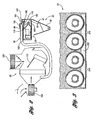
Figure 2 illustrates a simplified view of a HVAC assembly interacting with the dedicated climate controlled bin of the glove box assembly in accordance with the present invention; and -
Figure 3 illustrates a partial front view of the dedicated climate control bin having a removable liner in accordance with the present invention. - In the following description, several well-known features of an instrument panel and glove box are not shown or described so as not to obscure the present invention. Referring now to the drawings,
Figures 1 - 3 illustrate an exemplary embodiment of aglove box assembly 10 incorporated into aninstrument panel module 20 in accordance with the present invention. -
Glove box assembly 10 includes adoor 30 arranged to pivot between a closed position and an open position as best shown inFigures 1 and2 . In the open position,door 30 provides access to astorage bin 40 and a dedicated climate controlledbin 50. The climate controlledbin 50 is a separate bin and functions independently fromstorage bin 40. - The dedicated climate controlled
bin 50 has a rectangular shape and is arranged to interact with a vehicle HVAC system 60 (Figure 2 ) to provide selective cooled air to the climate controlledbin 50 while not cooling thestorage bin 40. The climate controlledbin 50 includes aseal 70 positioned on an outer perimeter of the bin and arranged to engagedoor 30 whendoor 30 is in a closed position. Alternatively,seal 70 could be positioned ondoor 30 so as to engage the outer perimeter of climate controlledbin 50 whendoor 30 is in the closed position. - As best shown in
Figure 2 , the dedicated climate controlled bin includes anair inlet 80 arranged to be connected to ahose 90 that is connected toHVAC system 60 for providing the climate controlled bin with selective cooled air fromHVAC system 60. Hose 90 is connected toHVAC system 60 down stream of anevaporator 100, but upstream of ablend air door 110 so as to provide cooled air to the dedicated climate controlledbin 50 when an air conditioning (AC) system is on regardless of a vehicle cabin temperature setting. More specifically, by placinghose 90 upstream ofblend air door 110 and thus heatercore 120, so long as the AC is on,hose 90 receives cooled air regardless of any warm air from theheater core 120 that is blended via theblend air door 110 to achieve a desired cabin temperature setting. - Air inlet 80 directs cooled air into an
upper portion 130 of the dedicated climate controlledbin 50.Upper portion 130 is separated from alower portion 140 by an internal, adjustableair vent arrangement 150. Theinternal venting arrangement 150 includes a perforatedpanel 160 fixed to climate controlledbin 50 and a translatable perforatedpanel 170 arranged to cooperate with fixed perforatedpanel 160 to open or block cooled air fromupper portion 130 tolower portion 140. More specifically,translatable panel 170 is arranged to slide so as to alignperforations panels lower portion 140 and thus cool any contents of the dedicated climate controlledbin 50, or to have theperforations 175 oftranslatable panel 170 not align with theperforations 165 of fixedpanel 160 so as to block off cooled air fromupper portion 130 and not cool the dedicated climate controlledbin 50. A vehicle operator can translatepanel 170 via a handle arrangement, such ashandle 180 shown inFigures 1 and2 . - The climate controlled
bin 50 also includes aremovable liner 200.Removable liner 200 can comprise many configurations depending on what type of contents are desired to be cooled in the climate controlled bin. In this exemplary embodiment,removable liner 200 includes fourscallops 210 arranged to receive beverage containers and prevent the containers from rolling in the dedicated climate controlledbin 50 as best shown inFigure 3 .Scallops 210 are sized such that typical beverage containers such as a 12 ounce can or a 20 ounce plastic bottle are held in place and up to four or either container can be easily placed and cooled in the dedicated climate controlledbin 50. - In operation, the dedicated climate controlled bin effectively provides a built in cooler for a vehicle that is incorporated into a glove box assembly while remaining independent from a storage area of the glove box assembly. With the dedicated climate controlled bin, a vehicle occupant can continue to use the storage area of the glove box while also being able to selectively cool desired items in a separate bin independent from the glove box storage area which will not receive the cooled air.
- The vehicle occupant can also cool desired items in the dedicated climate controlled bin with the AC on regardless of a desired vehicle cabin temperature. Thus, even if a vehicle occupant selects a cabin temperature that requires blending warm air with air conditioned air, the dedicated climate controlled bin will only receive cooled air from the HVAC unit because the dedicated climate controlled bin receives the cooled air from upstream of the blend air door.
Claims (8)
- A glove box (10) and heating, ventilation, and air conditioning unit (60) assembly for use in a vehicle, the glove box (10) including a storage bin (40), a climate controlled bin (50), and a cooled air inlet (80) arranged to receive cooled air from the vehicle heating, ventilation, and air conditioning unit (60), the heating, ventilation, and air conditioning unit (60) including an evaporator (100) operable to cool a first air stream, a heater core (120) operable to heat a second air stream, a blend air door (110) in fluid communication with and disposed between said evaporator (100) and said heater (120), whereby
said cooled air inlet (80) of the climate controlled bin (50) is connected to said heating, ventilating, and air conditioning unit by a conduit (90) having an intake downstream of said evaporator (100) and upstream of said blend air door (110) whereby so long as the air conditioning unit is on, said conduit (90) receives cooled air regardless of any warm air from the heater core (120), the warm air being blended via the blend air door (110) to achieve a desired cabin temperature setting and whereby
the downstream end of said conduit (90) is coupled to said climate controlled bin (50) to deliver cooled air to said climate controlled bin (50) independently of said storage bin (40). - A glove box (10) and heating, ventilation, and air conditioning unit (60) assembly according to claim 1, characterized in that the glove box (10) is closeable by a door (30) arranged to pivot between an open position providing access to the storage bin (40) and the climate controlled bin (50) and a closed position in which the storage bin (40) and climate controlled bin (50) are closed.
- A glove box (10) and heating, ventilation, and air conditioning unit (60) assembly according to claim 2, characterized in that a seal (70) is positioned on an outer perimeter of the climate controlled bin (50) and arranged to engage the door (30) in the closed position providing a thermal barrier for cooled air contained within an enclosed volume of the climate controlled bin (50).
- A glove box (10) and heating, ventilation, and air conditioning unit (60) assembly according to claim 3, characterized in that seal (70) is positioned on the door (30) and arranged to engage an outer perimeter of the glove box (10) to seal the bin (50) and provide a thermal barrier for cooled air contained within an enclosed volume of the climate controlled bin (50).
- A glove box (10) and heating, ventilation, and air conditioning unit (60) assembly according to any of the preceding claims, characterized in that the glove box (10) further includes a removable liner (200).
- A glove box (10) and heating, ventilation, and air conditioning unit (60) assembly according to claim 5, characterized in that the liner (200) is contoured to support at least one beverage container and prevent said container from rolling during vehicle operation.
- A glove box (10) and heating, ventilation, and air conditioning unit (60) assembly according to claim 6, characterized in that the contour of the liner (200) defines a plurality of scallops (210) arranged to support a plurality of beverage containers.
- A glove box (10) and heating, ventilation, and air conditioning unit (60) assembly according to claim 2, characterized in that the climate controlled bin (50) further includes an internal door arrangement (150) operable selectively to block a flow of cooled air from the vehicle heating, ventilating, and air conditioning unit (60).
Applications Claiming Priority (1)
| Application Number | Priority Date | Filing Date | Title |
|---|---|---|---|
| US11/267,690 US7389650B2 (en) | 2005-11-04 | 2005-11-04 | Cooled instrument panel compartment for a vehicle |
Publications (3)
| Publication Number | Publication Date |
|---|---|
| EP1782998A2 EP1782998A2 (en) | 2007-05-09 |
| EP1782998A3 EP1782998A3 (en) | 2007-06-20 |
| EP1782998B1 true EP1782998B1 (en) | 2010-04-14 |
Family
ID=37680650
Family Applications (1)
| Application Number | Title | Priority Date | Filing Date |
|---|---|---|---|
| EP06022736A Ceased EP1782998B1 (en) | 2005-11-04 | 2006-10-31 | Cooled instrument panel compartment for a vehicle |
Country Status (5)
| Country | Link |
|---|---|
| US (1) | US7389650B2 (en) |
| EP (1) | EP1782998B1 (en) |
| CN (1) | CN1958337A (en) |
| CA (1) | CA2565212C (en) |
| DE (1) | DE602006013569D1 (en) |
Families Citing this family (23)
| Publication number | Priority date | Publication date | Assignee | Title |
|---|---|---|---|---|
| US7726143B2 (en) * | 2006-12-21 | 2010-06-01 | Chrysler Group Llc | Vehicle cooled instrument panel compartment |
| US7780212B2 (en) * | 2007-05-29 | 2010-08-24 | Nissan Motor Co., Ltd. | Vehicle dashboard accommodation structure |
| FR2918013B1 (en) * | 2007-06-29 | 2009-10-02 | Peugeot Citroen Automobiles Sa | STORAGE CASE FOR MOTOR VEHICLE |
| DE202008002920U1 (en) * | 2008-02-29 | 2008-05-29 | GM Global Technology Operations, Inc., Detroit | Temperable charging compartment |
| US20110121599A1 (en) * | 2009-11-25 | 2011-05-26 | Delphi Technologies, Inc. | Integrated Center of Dash Food and Beverage Warmer/Cooler |
| US7891203B1 (en) | 2009-12-14 | 2011-02-22 | Honda Motor Co., Ltd. | Method and system for cooling items using vehicle HVAC system |
| DE102010000802A1 (en) * | 2010-01-12 | 2011-07-14 | Ford Global Technologies, LLC, Mich. | Air discharge installation for heating-, ventilation-, or air conditioning system of motor vehicle, has air discharge nozzle with nozzle housing and a nozzle insert, where nozzle housing is attached at air supply duct |
| US8784166B2 (en) * | 2010-03-30 | 2014-07-22 | Denso International America, Inc. | Heating, ventilating and air-conditioning apparatus |
| CN102529780A (en) * | 2011-12-23 | 2012-07-04 | 重庆长安汽车股份有限公司 | Automobile toolbox with cold storage function |
| CN102555875A (en) * | 2012-02-16 | 2012-07-11 | 奇瑞汽车股份有限公司 | Cooling and heating glove box |
| US9163863B1 (en) | 2014-10-15 | 2015-10-20 | Judith G. Armstrong | Beverage temperature control apparatus |
| FR3041301B1 (en) * | 2015-09-17 | 2018-08-31 | Renault Sas | ERGONOMIC CONTROL REFRIGERATED GLOVE BOX |
| CN105857010B (en) * | 2016-04-14 | 2018-07-03 | 力帆实业(集团)股份有限公司 | A kind of automobile and its mounted refrigerating case |
| CN108116185B (en) * | 2016-11-30 | 2020-02-07 | 比亚迪股份有限公司 | Automobile heat management system and electric automobile |
| JP6972926B2 (en) * | 2017-10-30 | 2021-11-24 | トヨタ自動車株式会社 | vehicle |
| CN107985214B (en) * | 2017-11-22 | 2020-05-15 | 北京汽车集团越野车有限公司 | Glove box and vehicle with same |
| CN107901811A (en) * | 2017-12-14 | 2018-04-13 | 江西创迪科技有限公司 | A kind of Vehicular refrigeration equipment |
| US11981240B2 (en) * | 2018-09-28 | 2024-05-14 | L&T Technology Services Limited | Controlling temperature inside a receptacle in a vehicle |
| FR3122150B1 (en) * | 2021-04-21 | 2025-09-26 | Psa Automobiles Sa | OPENING WALL WEDGING A CONDUIT OF A SYSTEM |
| WO2023036415A1 (en) | 2021-09-09 | 2023-03-16 | Volkswagen Aktiengesellschaft | Method, apparatus and computer program for adapting an environment in a cabin of a parked vehicle |
| US12065068B2 (en) * | 2022-05-02 | 2024-08-20 | Ford Global Technologies, Llc | Vehicle console having deployable heated shelf |
| US12109866B2 (en) * | 2022-09-21 | 2024-10-08 | Ford Global Technologies, Llc | Thermal management system for a vehicle |
| CN119872384A (en) * | 2025-01-07 | 2025-04-25 | 东风延锋汽车座舱系统有限公司 | Cold and warm glove box and automobile |
Family Cites Families (18)
| Publication number | Priority date | Publication date | Assignee | Title |
|---|---|---|---|---|
| US2902838A (en) * | 1956-07-19 | 1959-09-08 | Gen Motors Corp | Automobile refrigerating apparatus |
| JPS57138415A (en) | 1981-02-18 | 1982-08-26 | Nippon Denso Co Ltd | Car-loaded refrigerator |
| DE3739151A1 (en) | 1986-12-22 | 1988-07-28 | Bayerische Motoren Werke Ag | Cooler box for a motor vehicle |
| US4892138A (en) * | 1989-01-30 | 1990-01-09 | Bibik Jr Frank F | Beverage temperature controlling assembly for a vehicle |
| US5165646A (en) * | 1991-10-07 | 1992-11-24 | Gewecke Danny F | Auto dashboard drink conditioner |
| US5197775A (en) * | 1991-12-13 | 1993-03-30 | Ford Motor Company | Glove compartment |
| US5203833A (en) * | 1992-03-16 | 1993-04-20 | Howell David S | Food storage container heated and cooled by conditioned air in a motor vehicle |
| DE9418170U1 (en) | 1994-11-12 | 1995-01-12 | Laufer, Michael, Dipl.-Ing., 30459 Hannover | Cold or heat insulation of the glove compartment in motor vehicles and branching of a partial air flow from the installed air conditioning system along with regulation for cooling the glove compartment contents |
| US5701754A (en) * | 1995-09-29 | 1997-12-30 | Choi; Young Tai | Automobile refrigerator |
| DE19711832C1 (en) * | 1997-03-21 | 1998-10-22 | Happich Gmbh Gebr | Containers in a motor vehicle for storing beverages and / or food |
| WO2000013935A1 (en) | 1998-09-10 | 2000-03-16 | Richard Wayne De Beer | Storage unit for motor vehicles |
| US6155063A (en) * | 1999-07-29 | 2000-12-05 | Felde; Philip E. | Beverage temperature control system for a vehicle |
| US6231099B1 (en) * | 1999-10-15 | 2001-05-15 | Delphi Technologies, Inc. | Reconfigurable glove box bin |
| US6560983B1 (en) * | 2001-12-26 | 2003-05-13 | Werner Schimmeyer | Drink cooler |
| US6640551B1 (en) * | 2002-08-26 | 2003-11-04 | Whirlpool Corporation | Thermal conditioning beverage container holder |
| US6971697B2 (en) * | 2003-09-30 | 2005-12-06 | Morales Kimberly A | Liner-dispensing trash receptacle assembly for use in combination with a motor vehicle |
| US7073338B2 (en) | 2003-12-03 | 2006-07-11 | Lear Corporation | Thermally controlled storage space system for an interior cabin of a vehicle |
| JP4264894B2 (en) | 2004-03-01 | 2009-05-20 | 三菱自動車工業株式会社 | Glove box with air box |
-
2005
- 2005-11-04 US US11/267,690 patent/US7389650B2/en active Active
-
2006
- 2006-10-23 CA CA2565212A patent/CA2565212C/en not_active Expired - Fee Related
- 2006-10-31 EP EP06022736A patent/EP1782998B1/en not_active Ceased
- 2006-10-31 DE DE602006013569T patent/DE602006013569D1/en active Active
- 2006-11-02 CN CNA2006101380075A patent/CN1958337A/en active Pending
Also Published As
| Publication number | Publication date |
|---|---|
| CA2565212C (en) | 2014-02-25 |
| CN1958337A (en) | 2007-05-09 |
| US7389650B2 (en) | 2008-06-24 |
| DE602006013569D1 (en) | 2010-05-27 |
| EP1782998A2 (en) | 2007-05-09 |
| CA2565212A1 (en) | 2007-05-04 |
| EP1782998A3 (en) | 2007-06-20 |
| US20070101741A1 (en) | 2007-05-10 |
Similar Documents
| Publication | Publication Date | Title |
|---|---|---|
| CA2565212C (en) | Cooled instrument panel compartment for a vehicle | |
| CN101204936B (en) | Adjustable container holder operated by HAVC system | |
| US7073338B2 (en) | Thermally controlled storage space system for an interior cabin of a vehicle | |
| US7726143B2 (en) | Vehicle cooled instrument panel compartment | |
| US9718326B2 (en) | Device and method for heating and cooling storage containers | |
| CN1663840B (en) | Handschuhfach mit klimatisiertem fach | |
| WO2016157776A1 (en) | Vehicle air conditioner | |
| US5839293A (en) | Provision of conditioned air to a trunk of a vehicle | |
| KR101748202B1 (en) | Air conditioner for vehicles | |
| WO2016157775A1 (en) | Vehicle air conditioner | |
| KR200331118Y1 (en) | Coldness and warmth apparatus using of a vehicle air conditioning system | |
| WO2014036208A1 (en) | Dedicated floor bleed for an air conditioning system | |
| KR200145173Y1 (en) | Automotive Console with Air Ventilation Channel | |
| KR20040023359A (en) | Cup holder having air-conditioner system | |
| JP2000135935A (en) | Instrument panel container holder | |
| JP2004203341A (en) | Vehicle cup holder air conditioner | |
| US20060150654A1 (en) | Cup holder | |
| JP2004182157A (en) | Vehicle air conditioner | |
| KR100203042B1 (en) | Automotive glove box with air conditioner | |
| KR101950736B1 (en) | Air conditioner for vehicle | |
| KR19980024213U (en) | Cold and hot store using car's glove box | |
| EP1384607B1 (en) | A system for controlling the climate in the passenger compartment of a motor vehicle | |
| JPS58177707A (en) | Air conditioning device for automobile | |
| KR19980024609U (en) | Cold and hot storage using console box of car | |
| KR19980051536U (en) | Cooling and warming device in the car interior |
Legal Events
| Date | Code | Title | Description |
|---|---|---|---|
| PUAI | Public reference made under article 153(3) epc to a published international application that has entered the european phase |
Free format text: ORIGINAL CODE: 0009012 |
|
| AK | Designated contracting states |
Kind code of ref document: A2 Designated state(s): AT BE BG CH CY CZ DE DK EE ES FI FR GB GR HU IE IS IT LI LT LU LV MC NL PL PT RO SE SI SK TR |
|
| AX | Request for extension of the european patent |
Extension state: AL BA HR MK YU |
|
| PUAL | Search report despatched |
Free format text: ORIGINAL CODE: 0009013 |
|
| AK | Designated contracting states |
Kind code of ref document: A3 Designated state(s): AT BE BG CH CY CZ DE DK EE ES FI FR GB GR HU IE IS IT LI LT LU LV MC NL PL PT RO SE SI SK TR |
|
| AX | Request for extension of the european patent |
Extension state: AL BA HR MK YU |
|
| 17P | Request for examination filed |
Effective date: 20070910 |
|
| 17Q | First examination report despatched |
Effective date: 20071012 |
|
| AKX | Designation fees paid |
Designated state(s): DE FR GB IT |
|
| RAP1 | Party data changed (applicant data changed or rights of an application transferred) |
Owner name: CHRYSLER LLC |
|
| GRAP | Despatch of communication of intention to grant a patent |
Free format text: ORIGINAL CODE: EPIDOSNIGR1 |
|
| GRAS | Grant fee paid |
Free format text: ORIGINAL CODE: EPIDOSNIGR3 |
|
| GRAA | (expected) grant |
Free format text: ORIGINAL CODE: 0009210 |
|
| AK | Designated contracting states |
Kind code of ref document: B1 Designated state(s): DE FR GB IT |
|
| REG | Reference to a national code |
Ref country code: GB Ref legal event code: FG4D |
|
| RAP2 | Party data changed (patent owner data changed or rights of a patent transferred) |
Owner name: CHRYSLER GROUP LLC |
|
| REF | Corresponds to: |
Ref document number: 602006013569 Country of ref document: DE Date of ref document: 20100527 Kind code of ref document: P |
|
| PLBE | No opposition filed within time limit |
Free format text: ORIGINAL CODE: 0009261 |
|
| STAA | Information on the status of an ep patent application or granted ep patent |
Free format text: STATUS: NO OPPOSITION FILED WITHIN TIME LIMIT |
|
| 26N | No opposition filed |
Effective date: 20110117 |
|
| REG | Reference to a national code |
Ref country code: FR Ref legal event code: PLFP Year of fee payment: 10 |
|
| REG | Reference to a national code |
Ref country code: FR Ref legal event code: PLFP Year of fee payment: 11 |
|
| REG | Reference to a national code |
Ref country code: FR Ref legal event code: PLFP Year of fee payment: 12 |
|
| REG | Reference to a national code |
Ref country code: FR Ref legal event code: PLFP Year of fee payment: 13 |
|
| PGFP | Annual fee paid to national office [announced via postgrant information from national office to epo] |
Ref country code: GB Payment date: 20211027 Year of fee payment: 16 Ref country code: DE Payment date: 20211027 Year of fee payment: 16 |
|
| PGFP | Annual fee paid to national office [announced via postgrant information from national office to epo] |
Ref country code: IT Payment date: 20211021 Year of fee payment: 16 Ref country code: FR Payment date: 20211025 Year of fee payment: 16 |
|
| REG | Reference to a national code |
Ref country code: DE Ref legal event code: R119 Ref document number: 602006013569 Country of ref document: DE |
|
| GBPC | Gb: european patent ceased through non-payment of renewal fee |
Effective date: 20221031 |
|
| PG25 | Lapsed in a contracting state [announced via postgrant information from national office to epo] |
Ref country code: FR Free format text: LAPSE BECAUSE OF NON-PAYMENT OF DUE FEES Effective date: 20221031 Ref country code: DE Free format text: LAPSE BECAUSE OF NON-PAYMENT OF DUE FEES Effective date: 20230503 |
|
| PG25 | Lapsed in a contracting state [announced via postgrant information from national office to epo] |
Ref country code: IT Free format text: LAPSE BECAUSE OF NON-PAYMENT OF DUE FEES Effective date: 20221031 Ref country code: GB Free format text: LAPSE BECAUSE OF NON-PAYMENT OF DUE FEES Effective date: 20221031 |