EP1782920A1 - System for satin finishing of sheet metal by means of mechanically fixed flap wheels - Google Patents
System for satin finishing of sheet metal by means of mechanically fixed flap wheels Download PDFInfo
- Publication number
- EP1782920A1 EP1782920A1 EP06022590A EP06022590A EP1782920A1 EP 1782920 A1 EP1782920 A1 EP 1782920A1 EP 06022590 A EP06022590 A EP 06022590A EP 06022590 A EP06022590 A EP 06022590A EP 1782920 A1 EP1782920 A1 EP 1782920A1
- Authority
- EP
- European Patent Office
- Prior art keywords
- satin finishing
- mechanically fixed
- flap wheel
- satin
- sheet metal
- Prior art date
- Legal status (The legal status is an assumption and is not a legal conclusion. Google has not performed a legal analysis and makes no representation as to the accuracy of the status listed.)
- Granted
Links
- 239000002184 metal Substances 0.000 title claims abstract description 34
- 230000002093 peripheral effect Effects 0.000 abstract description 2
- 239000000463 material Substances 0.000 description 3
- 239000000853 adhesive Substances 0.000 description 2
- 230000001070 adhesive effect Effects 0.000 description 2
- 230000015572 biosynthetic process Effects 0.000 description 2
- 239000004744 fabric Substances 0.000 description 2
- 239000010802 sludge Substances 0.000 description 2
- XLYOFNOQVPJJNP-UHFFFAOYSA-N water Substances O XLYOFNOQVPJJNP-UHFFFAOYSA-N 0.000 description 2
- 230000004075 alteration Effects 0.000 description 1
- 230000001143 conditioned effect Effects 0.000 description 1
- 238000001816 cooling Methods 0.000 description 1
- 230000000593 degrading effect Effects 0.000 description 1
- 230000001419 dependent effect Effects 0.000 description 1
- 239000000428 dust Substances 0.000 description 1
- 238000005498 polishing Methods 0.000 description 1
- 239000011347 resin Substances 0.000 description 1
- 229920005989 resin Polymers 0.000 description 1
- 239000004576 sand Substances 0.000 description 1
- 238000011144 upstream manufacturing Methods 0.000 description 1
Images

Classifications
-
- B—PERFORMING OPERATIONS; TRANSPORTING
- B24—GRINDING; POLISHING
- B24B—MACHINES, DEVICES, OR PROCESSES FOR GRINDING OR POLISHING; DRESSING OR CONDITIONING OF ABRADING SURFACES; FEEDING OF GRINDING, POLISHING, OR LAPPING AGENTS
- B24B29/00—Machines or devices for polishing surfaces on work by means of tools made of soft or flexible material with or without the application of solid or liquid polishing agents
- B24B29/02—Machines or devices for polishing surfaces on work by means of tools made of soft or flexible material with or without the application of solid or liquid polishing agents designed for particular workpieces
- B24B29/06—Machines or devices for polishing surfaces on work by means of tools made of soft or flexible material with or without the application of solid or liquid polishing agents designed for particular workpieces for elongated workpieces having uniform cross-section in one main direction
-
- B—PERFORMING OPERATIONS; TRANSPORTING
- B24—GRINDING; POLISHING
- B24B—MACHINES, DEVICES, OR PROCESSES FOR GRINDING OR POLISHING; DRESSING OR CONDITIONING OF ABRADING SURFACES; FEEDING OF GRINDING, POLISHING, OR LAPPING AGENTS
- B24B29/00—Machines or devices for polishing surfaces on work by means of tools made of soft or flexible material with or without the application of solid or liquid polishing agents
-
- B—PERFORMING OPERATIONS; TRANSPORTING
- B24—GRINDING; POLISHING
- B24D—TOOLS FOR GRINDING, BUFFING OR SHARPENING
- B24D13/00—Wheels having flexibly-acting working parts, e.g. buffing wheels; Mountings therefor
- B24D13/02—Wheels having flexibly-acting working parts, e.g. buffing wheels; Mountings therefor acting by their periphery
- B24D13/04—Wheels having flexibly-acting working parts, e.g. buffing wheels; Mountings therefor acting by their periphery comprising a plurality of flaps or strips arranged around the axis
Definitions
- the present invention refers to a system for satin finishing of sheet metal by means of mechanically fixed flap wheels (that is, flap wheels whose flaps are mechanically fixed to the hub of the flap wheel), which comprises at least one satin finishing station - equipped with at least one mechanically fixed flap wheel with a horizontal axis and with means adapted to cause the at least one mechanically fixed flap wheel to rotate - and means adapted to cause the sheet metal being processed to slide longitudinally through the satin finishing stations.
- mechanically fixed flap wheels that is, flap wheels whose flaps are mechanically fixed to the hub of the flap wheel
- at least one satin finishing station - equipped with at least one mechanically fixed flap wheel with a horizontal axis and with means adapted to cause the at least one mechanically fixed flap wheel to rotate - and means adapted to cause the sheet metal being processed to slide longitudinally through the satin finishing stations.
- each finishing station comprises a pair of opposed finishing heads, each of which comprises a ring of abrasive cloth carried by a drive roller and by a roller which holds the abrasive cloth in contact with the surface to be processed.
- the finishing heads are positioned vertically and machine simultaneously the two opposite sides of a sheet metal fed in a per se known manner between the finishing heads.
- Flap wheels of new design are currently available on the market, referred to in the present description as "mechanically fixed flap wheels", in which the flaps are fixed mechanically to the hub: these mechanically fixed flap wheels are free from the drawbacks and limitations inherent in conventional flap wheels.
- Object of the present invention is to overcome the above-mentioned limits and drawbacks presented by satin finishing systems for sheet metal with sand belts and those with conventional flap wheels, allowing sheet metal to be satin finished -- with a uniformly even surface finish -- with a single mechanically fixed flap wheel, which has proved to be strong enough to be able to have the same width as the sheet metal to be satin finished.
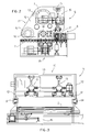
- Figure 1 shows diagrammatically a perspective view of the satin finishing system 1 according to the invention which comprises, in combination with each other:
- a characterising feature of the satin finishing system forming the subject matter of the present invention is the fact that the flap wheels 6 are mechanically fixed flap wheels, that is, the flaps 9 of each flap wheel 6 are fixed mechanically to the hub 10 of said wheel.
- each satin finishing station 5 comprises a mechanically fixed flap wheel 6 but, without departing from the scope of the invention, each satin finishing station 5 can comprise two or more mechanically fixed flap wheels 6, parallel to each other, and made to rotate by means 7.
- the mechanically fixed flap wheels 6 can be replaced by grinding wheels or any other of functionally equivalent abrasive means other than abrasive cloths or conventional flap wheels.
- the feed means are advantageously present at the beginning and at the end of the roller bed 2 and between two adjacent satin finishing stations 5.
- the heat produced during processing of the sheet metal by means of the mechanically fixed flap wheels 6 is less than that produced during processing by means of abrasive cloths or conventional flap wheels, during processing the sheet metal can be cooled by means of jets of air coming from delivery nozzles (omitted in the figures because they are per se known and in any case outside the scope of the present invention) placed upstream of each satin finishing station 5.
- the use of water as a cooling means with the consequent formation of sludge is thus avoided and it is possible to use a dust suction system, omitted in the figures because it is per se known and in any case outside the scope of the invention.
- Figure 2 shows diagrammatically a side view of one of the satin finishing stations 5 of Figure 1, whose inner parts are shown "in transparency”.
- the satin finishing station 5 of Figure 2 comprises a supporting structure 11, rocking around pivots 14 carried - in a per se known manner - by the support 3, inside which are placed at least:
- the supporting structure 11 consists of two side plates 12 (connected to each other by side members 13) which carry at least the mechanically fixed flap wheel 6, the means 7 adapted to make the mechanically fixed flap wheel 6 rotate, and the means 8 adapted to feed the sheet metal 4 through the at least one satin finishing station 5.
- each satin finishing station 5 advantageously further comprises adjustment means adapted to modify the speed of rotation of the flap wheel 6 and move it vertically.
- the adjustment means (not described in detail because they are per se known) comprise at least one sensor adapted to detect the current absorbed by the means 7 and a logic unit which, in response to a change in the current absorbed, modifies the intensity of the current supplied to the means 7 to keep the speed of rotation of the flap wheel 6 constant and controls means 15 adapted to move the supporting structure 11 vertically to keep the removal pressure of the flap wheel 6 constant;
- the means 15 consist of a hydraulic or pneumatic cylinder having one end connected to a side member 13 of the supporting structure 11 and the other to a bar 17 integral with the support 3.
- each satin finishing station 5 further comprises means (indicated as a whole with reference numeral 16 and not described herein because they are per se known) adapted to swing the satin finishing station 5 cyclically in a transverse direction with respect to the direction of feed of the sheet metal 4 to spread the wear on the mechanically fixed flap wheel 6 belonging to the satin finishing station 5 evenly along the whole length of said flap wheel.
- Figure 3 shows diagrammatically a head-on rear view of the satin finishing station 5 of Figure 2; visible in Figure 3 are the roller bed 2, the means 7 adapted to set in rotation the mechanically fixed flap wheel 6 (not visible in figure 3), the supporting structure 11 comprising the side plates 12 carried by the pivots 14 and connected by at least one side member 13, the means 15 adapted to move the supporting structure 11 vertically and the means 16 adapted to swing the satin finishing station 5 cyclically in a direction transversal to that of feeding of the sheet metal 4.
Landscapes
- Engineering & Computer Science (AREA)
- Mechanical Engineering (AREA)
- Polishing Bodies And Polishing Tools (AREA)
- Finish Polishing, Edge Sharpening, And Grinding By Specific Grinding Devices (AREA)
Abstract
Description
- The present invention refers to a system for satin finishing of sheet metal by means of mechanically fixed flap wheels (that is, flap wheels whose flaps are mechanically fixed to the hub of the flap wheel), which comprises at least one satin finishing station - equipped with at least one mechanically fixed flap wheel with a horizontal axis and with means adapted to cause the at least one mechanically fixed flap wheel to rotate - and means adapted to cause the sheet metal being processed to slide longitudinally through the satin finishing stations.
- For finishing (satin finishing and/or polishing) of sheet metal, systems with abrasive cloths are currently used, in which each finishing station comprises a pair of opposed finishing heads, each of which comprises a ring of abrasive cloth carried by a drive roller and by a roller which holds the abrasive cloth in contact with the surface to be processed.
- The finishing heads are positioned vertically and machine simultaneously the two opposite sides of a sheet metal fed in a per se known manner between the finishing heads.
- These known systems present numerous limits and drawbacks, amongst which:
- the abrasive cloths wear out very rapidly, drastically reducing their removal capacity and no longer guaranteeing the initial standard of finishing: it is therefore necessary to stop the system often to replace the worn-out cloths, which can sometimes be reused in the finishing heads that carry out rougher finishing;
- the heat produced during processing of sheet metal by means of the abrasive cloths makes it necessary to cool the sheets of metal with water, which results in the formation of sludge which must be removed.
- Also known to the art are systems for satin finishing of pipes by means of flap wheels, whose performance is nevertheless conditioned by the limitations inherent in the flap wheels traditionally used in the these systems, since it has been found experimentally that during satin finishing (also because of the heat that develops through friction between the flaps and the surface to be satin finished) the temperature of a conventional flap wheel (and in particular of its hub ) reaches such high values as (to be able) to cause a physical alteration in the components used to make the conventional flap wheel, degrading in particular the binding and cohesive characteristics of the material (normally a resin) used as adhesive to fix the flaps to the hub.
- This fact, together with the high speed of the wheel (which can reach 30 -- 35 m./s) means that the material used as adhesive loses (or can lose) its ability to retain the flaps in place, overcoming the centrifugal force acting on said flaps. It has in fact been found experimentally that the flaps gradually become detached from the wheel hub and consequently the life of the flap wheel and of its ability to remove material from the surface to be processed is reduced.
- The drawbacks and limitations inherent in conventional flap wheels have not thus far allowed flap wheel systems capable of satin finishing sheet metal with satisfactory results to be produced.
- In fact it has been found experimentally that the length of conventional flap wheels cannot exceed about 10 cm: to satin finish sheets of metal with a greater width it would be necessary to use two or more conventional flap wheels side by side but the satin finished sheet metal would have lines coinciding with the gaps that are inevitably present between the side-by-side flap wheels.
- Flap wheels of new design are currently available on the market, referred to in the present description as "mechanically fixed flap wheels", in which the flaps are fixed mechanically to the hub: these mechanically fixed flap wheels are free from the drawbacks and limitations inherent in conventional flap wheels.
- Mechanically fixed flap wheels are known, for example, from patent application number MI2005A000483 in the name of the applicant and are commercially available.
- Object of the present invention is to overcome the above-mentioned limits and drawbacks presented by satin finishing systems for sheet metal with sand belts and those with conventional flap wheels, allowing sheet metal to be satin finished -- with a uniformly even surface finish -- with a single mechanically fixed flap wheel, which has proved to be strong enough to be able to have the same width as the sheet metal to be satin finished.
- This object is achieved by means of a satin finishing system produced according to the present invention, which has the characterising features illustrated in claim 1; further advantageous characteristics of the invention form the subject matter of the dependent claims.
- Further characteristics of the invention will be made clearer by the detailed description that follows, referring to a purely exemplifying and therefore non-limiting embodiment, illustrated in the appended drawings, wherein:
- Figure 1 is a diagrammatic perspective view of a satin finishing system according to the invention;
- Figure 2 is a diagrammatic side view of one of the satin finishing stations of Figure 1, in which the inner parts have been shown "in transparency";
- Figure 3 is a diagrammatic head-on rear view of the satin finishing station of Figure 2.
- In the appended figures like elements will be identified by the same reference numerals.
- Figure 1 shows diagrammatically a perspective view of the satin finishing system 1 according to the invention which comprises, in combination with each other:
- a bed of
rollers 2 with horizontal axes, mounted idly and carried by a support 3, on which asheet metal 4 slides: theroller bed 2, the support 3 and the sheets ofmetal 4 will not be described because they are per se known; - at least one satin finishing station 5 (better described with reference to Figures 2 and 3), equipped with at least one
flap wheel 6 and with means 7 (not shown in Figure 1) adapted to set in rotation the at least oneflap wheel 6; in Figure 1 sixsatin finishing stations 5 are shown, which carry out an increasingly high standard of satin finishing; - feed means 8 (not shown in figure 1), adapted to feed the
sheet metal 4 along theroller bed 2 and through the at least onefinishing station 5. - A characterising feature of the satin finishing system forming the subject matter of the present invention is the fact that the
flap wheels 6 are mechanically fixed flap wheels, that is, theflaps 9 of eachflap wheel 6 are fixed mechanically to thehub 10 of said wheel. - In the embodiment described herein each
satin finishing station 5 comprises a mechanically fixedflap wheel 6 but, without departing from the scope of the invention, eachsatin finishing station 5 can comprise two or more mechanically fixedflap wheels 6, parallel to each other, and made to rotate bymeans 7. - Without departing from the scope of the invention, the mechanically fixed
flap wheels 6 can be replaced by grinding wheels or any other of functionally equivalent abrasive means other than abrasive cloths or conventional flap wheels. - The feed means are advantageously present at the beginning and at the end of the
roller bed 2 and between two adjacentsatin finishing stations 5. - Furthermore, since the heat produced during processing of the sheet metal by means of the mechanically fixed
flap wheels 6 is less than that produced during processing by means of abrasive cloths or conventional flap wheels, during processing the sheet metal can be cooled by means of jets of air coming from delivery nozzles (omitted in the figures because they are per se known and in any case outside the scope of the present invention) placed upstream of eachsatin finishing station 5. The use of water as a cooling means with the consequent formation of sludge is thus avoided and it is possible to use a dust suction system, omitted in the figures because it is per se known and in any case outside the scope of the invention. - For the sake of simplicity of the graphic representation, only one
satin finishing station 5, the mechanically fixedflap wheel 6 belonging to thestation 5, and theflaps 9 and thehub 10 belonging to said mechanically fixed flap wheel have been identified by the relative reference numerals in Figure 1. - Figure 2 shows diagrammatically a side view of one of the
satin finishing stations 5 of Figure 1, whose inner parts are shown "in transparency". - The
satin finishing station 5 of Figure 2 comprises a supportingstructure 11, rocking aroundpivots 14 carried - in a per se known manner - by the support 3, inside which are placed at least: - a mechanically fixed
flap wheel 6, - means 7 (per se known), adapted to make the mechanically fixed
flap wheel 6 rotate and consisting, in the embodiment described herein, of at least one electric motor connected in a per se known manner to the mechanically fixedflap wheel 6; - means 8 (per se known), adapted to feed the
sheet metal 4 through thesatin finishing station 5 and consisting, in the embodiment described herein, of at least one motorised roller acting on thesheet metal 4. - In the embodiment described herein the supporting
structure 11 consists of two side plates 12 (connected to each other by side members 13) which carry at least the mechanically fixedflap wheel 6, themeans 7 adapted to make the mechanically fixedflap wheel 6 rotate, and themeans 8 adapted to feed thesheet metal 4 through the at least onesatin finishing station 5. - In Figure 2 the ends of the two
side members 13 can be seen, one of which can be seen in Figure 3. - To compensate for wear on the mechanically fixed
flap wheel 6 and to keep its peripheral speed and removal pressure constant, eachsatin finishing station 5 advantageously further comprises adjustment means adapted to modify the speed of rotation of theflap wheel 6 and move it vertically. - For example, the adjustment means (not described in detail because they are per se known) comprise at least one sensor adapted to detect the current absorbed by the
means 7 and a logic unit which, in response to a change in the current absorbed, modifies the intensity of the current supplied to themeans 7 to keep the speed of rotation of theflap wheel 6 constant and controls means 15 adapted to move the supportingstructure 11 vertically to keep the removal pressure of theflap wheel 6 constant; in the embodiment described herein, themeans 15 consist of a hydraulic or pneumatic cylinder having one end connected to aside member 13 of the supportingstructure 11 and the other to abar 17 integral with the support 3. - If the width of the
sheet metal 4 is less than the length of the mechanically fixedflap wheels 6, eachsatin finishing station 5 further comprises means (indicated as a whole withreference numeral 16 and not described herein because they are per se known) adapted to swing thesatin finishing station 5 cyclically in a transverse direction with respect to the direction of feed of thesheet metal 4 to spread the wear on the mechanically fixedflap wheel 6 belonging to thesatin finishing station 5 evenly along the whole length of said flap wheel. - Figure 3 shows diagrammatically a head-on rear view of the
satin finishing station 5 of Figure 2; visible in Figure 3 are theroller bed 2, themeans 7 adapted to set in rotation the mechanically fixed flap wheel 6 (not visible in figure 3), the supportingstructure 11 comprising theside plates 12 carried by thepivots 14 and connected by at least oneside member 13, themeans 15 adapted to move the supportingstructure 11 vertically and themeans 16 adapted to swing thesatin finishing station 5 cyclically in a direction transversal to that of feeding of thesheet metal 4. - Without departing from the scope of the invention, a person skilled in the art can make to the satin finishing system previously described all the changes and improvements suggested by normal experience and/or by the natural evolution of the art.
Claims (7)
- A system (1) for satin finishing, by means of flap wheels (6), of sheet metal (4) moving on a bed of rollers (2) with a horizontal axis carried by a support (3), which comprises in combination with each other:- at least one satin finishing station (5) equipped with at least one flap wheel (6) and with means (7) adapted to cause the at least one flap wheel to rotate (6);- feed means (8), adapted to feed the sheet metal (4) along the roller bed (2) and through the at least one satin finishing station (5);characterised in that the at least one flap wheel (6) is a mechanically fixed flap wheel, whose flaps (9) are mechanically fixed to the hub (10) of the flap wheel (6).
- A satin finishing system (1) as in claim 1, characterised in that each satin finishing station (5) comprises a supporting structure (11), rocking around pivots (14) carried by the support (3), inside which is placed at least one mechanically fixed flap wheel (6), means (7) adapted to make the mechanically fixed flap wheel (6) rotate, and means (8) adapted to feed the sheets of metal (4) through the satin finishing station (5).
- A satin finishing system (1) as in claim 2, characterised in that the supporting structure (11) consists of two side plates (12) connected to each other by means of the side member (13) and in that the at least one mechanically fixed flap wheel (6), the means (7) adapted to make the at least one flap wheel rotate and the means (8) adapted to feed the sheets of metal (4) through the satin finishing station (5) are carried by the side plates (12).
- A satin finishing system (1) as in claim 2, characterised in that the means (7) adapted to cause the at least one mechanically fixed flap wheel (6) to rotate consist of at least one electric motor connected to the at least one mechanically fixed flap wheel (6).
- A satin finishing system (1) as in claim 2 characterised in that the means (8) adapted to feed the sheet metal (4) through the at least one satin finishing station (5) consist of at least one motorised roller acting on the sheet metal (4).
- A satin finishing system (1) as in claim 1, characterised in that each satin finishing station (5) further comprises adjustment means adapted to change the speed of rotation of the at least one mechanically fixed flap wheel (6) and move it vertically.
- A satin finishing system (1) as in at least one of the preceding claims for satin finishing of sheets of metal (4) having a width smaller than the length of the at least one mechanically fixed flap wheel (6), characterised in that each satin finishing station (5) further comprises means (16) adapted to swing the satin finishing station (5) cyclically in a direction transversal to the direction of feed of the sheet metal (4) to spread the wear of the at least one mechanically fixed flap wheel (6) belonging to the satin finishing station (5) evenly along the whole length of said flap wheel.
Applications Claiming Priority (1)
| Application Number | Priority Date | Filing Date | Title |
|---|---|---|---|
| IT002123A ITMI20052123A1 (en) | 2005-11-08 | 2005-11-08 | PLANT FOR SATIN FINISHING OF SHEETS BY LAMELLAR WHEELS WITH MECHANICAL FIXING |
Publications (2)
| Publication Number | Publication Date |
|---|---|
| EP1782920A1 true EP1782920A1 (en) | 2007-05-09 |
| EP1782920B1 EP1782920B1 (en) | 2013-08-21 |
Family
ID=37495182
Family Applications (1)
| Application Number | Title | Priority Date | Filing Date |
|---|---|---|---|
| EP06022590.1A Not-in-force EP1782920B1 (en) | 2005-11-08 | 2006-10-30 | System for satin finishing of sheet metal by means of mechanically fixed flap wheels |
Country Status (6)
| Country | Link |
|---|---|
| US (1) | US20070111646A1 (en) |
| EP (1) | EP1782920B1 (en) |
| JP (1) | JP2007130753A (en) |
| KR (1) | KR20070049557A (en) |
| CN (1) | CN1962193A (en) |
| IT (1) | ITMI20052123A1 (en) |
Cited By (3)
| Publication number | Priority date | Publication date | Assignee | Title |
|---|---|---|---|---|
| CN105583702A (en) * | 2016-01-27 | 2016-05-18 | 郑胜火 | Board polishing machine |
| CN108177041A (en) * | 2017-12-29 | 2018-06-19 | 浙江潮城互联网科技有限公司 | For the surface finishing device of photovoltaic bracket |
| CN108202290A (en) * | 2018-02-11 | 2018-06-26 | 谢斌 | Polissoir before a kind of teaching wooden rule production |
Families Citing this family (1)
| Publication number | Priority date | Publication date | Assignee | Title |
|---|---|---|---|---|
| CN102672569A (en) * | 2011-03-07 | 2012-09-19 | 吴江市中信科技有限公司 | Polishing machine |
Citations (8)
| Publication number | Priority date | Publication date | Assignee | Title |
|---|---|---|---|---|
| GB392692A (en) * | 1931-03-10 | 1933-05-25 | Budd Int Corp | Improvements in or relating to a method of and machine for removing projections suchas flash from metal sheets |
| US3645049A (en) | 1968-10-21 | 1972-02-29 | Minnesota Mining & Mfg | Wide flap wheel |
| GB1461570A (en) * | 1973-04-13 | 1977-01-13 | Hawker Siddeley Aviation Ltd | Deburring of workpieces |
| DE3803857C1 (en) * | 1988-02-09 | 1988-12-01 | Paul Dipl.-Ing. Ernst (Fh), 6925 Eschelbronn, De | Grinding machine for deburring and regrinding flat metal parts |
| US5921848A (en) | 1995-03-17 | 1999-07-13 | Flat Rock Metal, Inc. | Multi-directional abrading machine |
| EP1350600A1 (en) | 2002-04-02 | 2003-10-08 | Olimpia 80 SRL | Apparatus and procedure for surface finishing of pipes by means of lamellar wheels |
| WO2003092956A1 (en) | 2002-05-02 | 2003-11-13 | Costa Levigatrici Spa | Sanding machine |
| EP1704967A1 (en) | 2005-03-23 | 2006-09-27 | Olimpia 80 SRL | Flap wheel, in particular flap wheel for satin finishing systems for pipes or for sheet metal and method of producing the same |
Family Cites Families (8)
| Publication number | Priority date | Publication date | Assignee | Title |
|---|---|---|---|---|
| US4646473A (en) * | 1984-05-08 | 1987-03-03 | Udviklingscentret Hansen | Method and apparatus for finishing surfaces |
| IT1169618B (en) * | 1983-10-27 | 1987-06-03 | Dmc Div Mecc Cast | SANDING MACHINE FOR WOOD PANELS |
| US4733500A (en) * | 1985-07-11 | 1988-03-29 | Timesavers, Inc. | Wood surface treatment method and system employing tandemly oriented cross-belts and rotary abraders |
| JPS62152667A (en) * | 1986-08-08 | 1987-07-07 | Nec Corp | Thin plate grinding device |
| US5468173A (en) * | 1993-09-30 | 1995-11-21 | Winton, Iii; George R. | Automatic deburring machine |
| JP3010462B2 (en) * | 1994-02-18 | 2000-02-21 | 株式会社日立製作所 | Automatic polishing equipment |
| JPH1110517A (en) * | 1997-06-18 | 1999-01-19 | Hotani:Kk | Brush roll machine |
| JP4007420B2 (en) * | 2002-03-19 | 2007-11-14 | 株式会社丸源鐵工所 | The buffler in the buffalo polishing machine |
-
2005
- 2005-11-08 IT IT002123A patent/ITMI20052123A1/en unknown
-
2006
- 2006-10-30 EP EP06022590.1A patent/EP1782920B1/en not_active Not-in-force
- 2006-10-31 KR KR1020060106214A patent/KR20070049557A/en not_active Withdrawn
- 2006-11-02 US US11/591,545 patent/US20070111646A1/en not_active Abandoned
- 2006-11-07 CN CNA2006101385492A patent/CN1962193A/en active Pending
- 2006-11-07 JP JP2006301411A patent/JP2007130753A/en active Pending
Patent Citations (8)
| Publication number | Priority date | Publication date | Assignee | Title |
|---|---|---|---|---|
| GB392692A (en) * | 1931-03-10 | 1933-05-25 | Budd Int Corp | Improvements in or relating to a method of and machine for removing projections suchas flash from metal sheets |
| US3645049A (en) | 1968-10-21 | 1972-02-29 | Minnesota Mining & Mfg | Wide flap wheel |
| GB1461570A (en) * | 1973-04-13 | 1977-01-13 | Hawker Siddeley Aviation Ltd | Deburring of workpieces |
| DE3803857C1 (en) * | 1988-02-09 | 1988-12-01 | Paul Dipl.-Ing. Ernst (Fh), 6925 Eschelbronn, De | Grinding machine for deburring and regrinding flat metal parts |
| US5921848A (en) | 1995-03-17 | 1999-07-13 | Flat Rock Metal, Inc. | Multi-directional abrading machine |
| EP1350600A1 (en) | 2002-04-02 | 2003-10-08 | Olimpia 80 SRL | Apparatus and procedure for surface finishing of pipes by means of lamellar wheels |
| WO2003092956A1 (en) | 2002-05-02 | 2003-11-13 | Costa Levigatrici Spa | Sanding machine |
| EP1704967A1 (en) | 2005-03-23 | 2006-09-27 | Olimpia 80 SRL | Flap wheel, in particular flap wheel for satin finishing systems for pipes or for sheet metal and method of producing the same |
Cited By (3)
| Publication number | Priority date | Publication date | Assignee | Title |
|---|---|---|---|---|
| CN105583702A (en) * | 2016-01-27 | 2016-05-18 | 郑胜火 | Board polishing machine |
| CN108177041A (en) * | 2017-12-29 | 2018-06-19 | 浙江潮城互联网科技有限公司 | For the surface finishing device of photovoltaic bracket |
| CN108202290A (en) * | 2018-02-11 | 2018-06-26 | 谢斌 | Polissoir before a kind of teaching wooden rule production |
Also Published As
| Publication number | Publication date |
|---|---|
| JP2007130753A (en) | 2007-05-31 |
| ITMI20052123A1 (en) | 2007-05-09 |
| KR20070049557A (en) | 2007-05-11 |
| US20070111646A1 (en) | 2007-05-17 |
| CN1962193A (en) | 2007-05-16 |
| EP1782920B1 (en) | 2013-08-21 |
Similar Documents
| Publication | Publication Date | Title |
|---|---|---|
| JP3044289B2 (en) | Deburring device | |
| KR200489598Y1 (en) | Pre-grinding machine for cold-drawn steel bars for rack bars | |
| EP1208941A2 (en) | Method and machine for grinding coated sheets of glass | |
| WO2012046360A1 (en) | Plate glass conveyance device and chamfering device provided with same | |
| CN111002192B (en) | Automatic deburring machine for steel plate | |
| CA2496743C (en) | Sanding machine and method of sanding a workpiece | |
| CN111266951A (en) | Adjustable three-sand-frame metal sander | |
| EP1782920A1 (en) | System for satin finishing of sheet metal by means of mechanically fixed flap wheels | |
| CN209754834U (en) | A drying plate sander | |
| JP3727300B2 (en) | Chamfering device for plate material | |
| SE462078B (en) | SET FOR BAND GRINDING OF METAL AND METAL ALLOY PARTS | |
| KR20230022662A (en) | Stone composite panel polishing system | |
| CN211029447U (en) | Plane sander | |
| CN219882056U (en) | Chopping board processing production line | |
| CN119217194A (en) | Metal sheet trimming device | |
| JPH1015798A (en) | Deburring device | |
| JPH11241231A5 (en) | ||
| CN206010750U (en) | A kind of automatic stone buffing machine | |
| WO2009071093A1 (en) | Grinding apparatus and apparatus for grinding a surface on plate-shaped items | |
| CN115008290A (en) | Polishing apparatus and polishing method | |
| EP1625914B1 (en) | Satin finishing system with flap wheels for shaped tubes | |
| CN214080652U (en) | Mirror edge grinding machine | |
| HK1103050A (en) | System for satin finishing of sheet metal by means of mechanically fixed flap wheels | |
| CN102152205A (en) | Grinding machine | |
| JPH04176554A (en) | Belt sander machine of multistep head type |
Legal Events
| Date | Code | Title | Description |
|---|---|---|---|
| PUAI | Public reference made under article 153(3) epc to a published international application that has entered the european phase |
Free format text: ORIGINAL CODE: 0009012 |
|
| AK | Designated contracting states |
Kind code of ref document: A1 Designated state(s): AT BE BG CH CY CZ DE DK EE ES FI FR GB GR HU IE IS IT LI LT LU LV MC NL PL PT RO SE SI SK TR |
|
| AX | Request for extension of the european patent |
Extension state: AL BA HR MK YU |
|
| 17P | Request for examination filed |
Effective date: 20071107 |
|
| AKX | Designation fees paid |
Designated state(s): AT BE BG CH CY CZ DE DK EE ES FI FR GB GR HU IE IS IT LI LT LU LV MC NL PL PT RO SE SI SK TR |
|
| 17Q | First examination report despatched |
Effective date: 20081104 |
|
| GRAP | Despatch of communication of intention to grant a patent |
Free format text: ORIGINAL CODE: EPIDOSNIGR1 |
|
| GRAS | Grant fee paid |
Free format text: ORIGINAL CODE: EPIDOSNIGR3 |
|
| GRAA | (expected) grant |
Free format text: ORIGINAL CODE: 0009210 |
|
| AK | Designated contracting states |
Kind code of ref document: B1 Designated state(s): AT BE BG CH CY CZ DE DK EE ES FI FR GB GR HU IE IS IT LI LT LU LV MC NL PL PT RO SE SI SK TR |
|
| REG | Reference to a national code |
Ref country code: GB Ref legal event code: FG4D |
|
| REG | Reference to a national code |
Ref country code: CH Ref legal event code: EP |
|
| REG | Reference to a national code |
Ref country code: AT Ref legal event code: REF Ref document number: 627773 Country of ref document: AT Kind code of ref document: T Effective date: 20130915 |
|
| REG | Reference to a national code |
Ref country code: IE Ref legal event code: FG4D |
|
| REG | Reference to a national code |
Ref country code: DE Ref legal event code: R096 Ref document number: 602006037927 Country of ref document: DE Effective date: 20131017 |
|
| REG | Reference to a national code |
Ref country code: AT Ref legal event code: MK05 Ref document number: 627773 Country of ref document: AT Kind code of ref document: T Effective date: 20130821 Ref country code: NL Ref legal event code: VDEP Effective date: 20130821 |
|
| REG | Reference to a national code |
Ref country code: LT Ref legal event code: MG4D |
|
| PG25 | Lapsed in a contracting state [announced via postgrant information from national office to epo] |
Ref country code: AT Free format text: LAPSE BECAUSE OF FAILURE TO SUBMIT A TRANSLATION OF THE DESCRIPTION OR TO PAY THE FEE WITHIN THE PRESCRIBED TIME-LIMIT Effective date: 20130821 Ref country code: CY Free format text: LAPSE BECAUSE OF FAILURE TO SUBMIT A TRANSLATION OF THE DESCRIPTION OR TO PAY THE FEE WITHIN THE PRESCRIBED TIME-LIMIT Effective date: 20130717 Ref country code: IS Free format text: LAPSE BECAUSE OF FAILURE TO SUBMIT A TRANSLATION OF THE DESCRIPTION OR TO PAY THE FEE WITHIN THE PRESCRIBED TIME-LIMIT Effective date: 20131221 Ref country code: SE Free format text: LAPSE BECAUSE OF FAILURE TO SUBMIT A TRANSLATION OF THE DESCRIPTION OR TO PAY THE FEE WITHIN THE PRESCRIBED TIME-LIMIT Effective date: 20130821 Ref country code: LT Free format text: LAPSE BECAUSE OF FAILURE TO SUBMIT A TRANSLATION OF THE DESCRIPTION OR TO PAY THE FEE WITHIN THE PRESCRIBED TIME-LIMIT Effective date: 20130821 Ref country code: PT Free format text: LAPSE BECAUSE OF FAILURE TO SUBMIT A TRANSLATION OF THE DESCRIPTION OR TO PAY THE FEE WITHIN THE PRESCRIBED TIME-LIMIT Effective date: 20131223 |
|
| PG25 | Lapsed in a contracting state [announced via postgrant information from national office to epo] |
Ref country code: LV Free format text: LAPSE BECAUSE OF FAILURE TO SUBMIT A TRANSLATION OF THE DESCRIPTION OR TO PAY THE FEE WITHIN THE PRESCRIBED TIME-LIMIT Effective date: 20130821 Ref country code: ES Free format text: LAPSE BECAUSE OF FAILURE TO SUBMIT A TRANSLATION OF THE DESCRIPTION OR TO PAY THE FEE WITHIN THE PRESCRIBED TIME-LIMIT Effective date: 20130821 Ref country code: GR Free format text: LAPSE BECAUSE OF FAILURE TO SUBMIT A TRANSLATION OF THE DESCRIPTION OR TO PAY THE FEE WITHIN THE PRESCRIBED TIME-LIMIT Effective date: 20131122 Ref country code: FI Free format text: LAPSE BECAUSE OF FAILURE TO SUBMIT A TRANSLATION OF THE DESCRIPTION OR TO PAY THE FEE WITHIN THE PRESCRIBED TIME-LIMIT Effective date: 20130821 Ref country code: PL Free format text: LAPSE BECAUSE OF FAILURE TO SUBMIT A TRANSLATION OF THE DESCRIPTION OR TO PAY THE FEE WITHIN THE PRESCRIBED TIME-LIMIT Effective date: 20130821 Ref country code: SI Free format text: LAPSE BECAUSE OF FAILURE TO SUBMIT A TRANSLATION OF THE DESCRIPTION OR TO PAY THE FEE WITHIN THE PRESCRIBED TIME-LIMIT Effective date: 20130821 Ref country code: BE Free format text: LAPSE BECAUSE OF FAILURE TO SUBMIT A TRANSLATION OF THE DESCRIPTION OR TO PAY THE FEE WITHIN THE PRESCRIBED TIME-LIMIT Effective date: 20130821 |
|
| PG25 | Lapsed in a contracting state [announced via postgrant information from national office to epo] |
Ref country code: CY Free format text: LAPSE BECAUSE OF FAILURE TO SUBMIT A TRANSLATION OF THE DESCRIPTION OR TO PAY THE FEE WITHIN THE PRESCRIBED TIME-LIMIT Effective date: 20130821 |
|
| PG25 | Lapsed in a contracting state [announced via postgrant information from national office to epo] |
Ref country code: EE Free format text: LAPSE BECAUSE OF FAILURE TO SUBMIT A TRANSLATION OF THE DESCRIPTION OR TO PAY THE FEE WITHIN THE PRESCRIBED TIME-LIMIT Effective date: 20130821 Ref country code: SK Free format text: LAPSE BECAUSE OF FAILURE TO SUBMIT A TRANSLATION OF THE DESCRIPTION OR TO PAY THE FEE WITHIN THE PRESCRIBED TIME-LIMIT Effective date: 20130821 Ref country code: NL Free format text: LAPSE BECAUSE OF FAILURE TO SUBMIT A TRANSLATION OF THE DESCRIPTION OR TO PAY THE FEE WITHIN THE PRESCRIBED TIME-LIMIT Effective date: 20130821 Ref country code: RO Free format text: LAPSE BECAUSE OF FAILURE TO SUBMIT A TRANSLATION OF THE DESCRIPTION OR TO PAY THE FEE WITHIN THE PRESCRIBED TIME-LIMIT Effective date: 20130821 Ref country code: DK Free format text: LAPSE BECAUSE OF FAILURE TO SUBMIT A TRANSLATION OF THE DESCRIPTION OR TO PAY THE FEE WITHIN THE PRESCRIBED TIME-LIMIT Effective date: 20130821 Ref country code: CZ Free format text: LAPSE BECAUSE OF FAILURE TO SUBMIT A TRANSLATION OF THE DESCRIPTION OR TO PAY THE FEE WITHIN THE PRESCRIBED TIME-LIMIT Effective date: 20130821 |
|
| PG25 | Lapsed in a contracting state [announced via postgrant information from national office to epo] |
Ref country code: MC Free format text: LAPSE BECAUSE OF FAILURE TO SUBMIT A TRANSLATION OF THE DESCRIPTION OR TO PAY THE FEE WITHIN THE PRESCRIBED TIME-LIMIT Effective date: 20130821 |
|
| REG | Reference to a national code |
Ref country code: CH Ref legal event code: PL |
|
| PLBE | No opposition filed within time limit |
Free format text: ORIGINAL CODE: 0009261 |
|
| STAA | Information on the status of an ep patent application or granted ep patent |
Free format text: STATUS: NO OPPOSITION FILED WITHIN TIME LIMIT |
|
| GBPC | Gb: european patent ceased through non-payment of renewal fee |
Effective date: 20131121 |
|
| 26N | No opposition filed |
Effective date: 20140522 |
|
| REG | Reference to a national code |
Ref country code: IE Ref legal event code: MM4A |
|
| PG25 | Lapsed in a contracting state [announced via postgrant information from national office to epo] |
Ref country code: LI Free format text: LAPSE BECAUSE OF NON-PAYMENT OF DUE FEES Effective date: 20131031 Ref country code: CH Free format text: LAPSE BECAUSE OF NON-PAYMENT OF DUE FEES Effective date: 20131031 |
|
| REG | Reference to a national code |
Ref country code: DE Ref legal event code: R119 Ref document number: 602006037927 Country of ref document: DE Effective date: 20140501 |
|
| REG | Reference to a national code |
Ref country code: FR Ref legal event code: ST Effective date: 20140630 |
|
| PG25 | Lapsed in a contracting state [announced via postgrant information from national office to epo] |
Ref country code: DE Free format text: LAPSE BECAUSE OF NON-PAYMENT OF DUE FEES Effective date: 20140501 Ref country code: FR Free format text: LAPSE BECAUSE OF NON-PAYMENT OF DUE FEES Effective date: 20131031 |
|
| PG25 | Lapsed in a contracting state [announced via postgrant information from national office to epo] |
Ref country code: IE Free format text: LAPSE BECAUSE OF NON-PAYMENT OF DUE FEES Effective date: 20131030 |
|
| PG25 | Lapsed in a contracting state [announced via postgrant information from national office to epo] |
Ref country code: GB Free format text: LAPSE BECAUSE OF NON-PAYMENT OF DUE FEES Effective date: 20131121 |
|
| PG25 | Lapsed in a contracting state [announced via postgrant information from national office to epo] |
Ref country code: TR Free format text: LAPSE BECAUSE OF FAILURE TO SUBMIT A TRANSLATION OF THE DESCRIPTION OR TO PAY THE FEE WITHIN THE PRESCRIBED TIME-LIMIT Effective date: 20130821 |
|
| PG25 | Lapsed in a contracting state [announced via postgrant information from national office to epo] |
Ref country code: BG Free format text: LAPSE BECAUSE OF FAILURE TO SUBMIT A TRANSLATION OF THE DESCRIPTION OR TO PAY THE FEE WITHIN THE PRESCRIBED TIME-LIMIT Effective date: 20130821 Ref country code: HU Free format text: LAPSE BECAUSE OF FAILURE TO SUBMIT A TRANSLATION OF THE DESCRIPTION OR TO PAY THE FEE WITHIN THE PRESCRIBED TIME-LIMIT; INVALID AB INITIO Effective date: 20061030 Ref country code: LU Free format text: LAPSE BECAUSE OF NON-PAYMENT OF DUE FEES Effective date: 20131030 |
|
| PGFP | Annual fee paid to national office [announced via postgrant information from national office to epo] |
Ref country code: IT Payment date: 20181029 Year of fee payment: 13 |
|
| PG25 | Lapsed in a contracting state [announced via postgrant information from national office to epo] |
Ref country code: IT Free format text: LAPSE BECAUSE OF NON-PAYMENT OF DUE FEES Effective date: 20191030 |