EP1782553B1 - Vorrichtung und verfahren zum erhalten von verzögerungs-diversity - Google Patents
Vorrichtung und verfahren zum erhalten von verzögerungs-diversity Download PDFInfo
- Publication number
- EP1782553B1 EP1782553B1 EP04764569A EP04764569A EP1782553B1 EP 1782553 B1 EP1782553 B1 EP 1782553B1 EP 04764569 A EP04764569 A EP 04764569A EP 04764569 A EP04764569 A EP 04764569A EP 1782553 B1 EP1782553 B1 EP 1782553B1
- Authority
- EP
- European Patent Office
- Prior art keywords
- values
- sequence
- input sequence
- shifted
- copy
- Prior art date
- Legal status (The legal status is an assumption and is not a legal conclusion. Google has not performed a legal analysis and makes no representation as to the accuracy of the status listed.)
- Expired - Fee Related
Links
Images


Classifications
-
- H—ELECTRICITY
- H04—ELECTRIC COMMUNICATION TECHNIQUE
- H04B—TRANSMISSION
- H04B7/00—Radio transmission systems, i.e. using radiation field
- H04B7/02—Diversity systems; Multi-antenna system, i.e. transmission or reception using multiple antennas
- H04B7/04—Diversity systems; Multi-antenna system, i.e. transmission or reception using multiple antennas using two or more spaced independent antennas
- H04B7/06—Diversity systems; Multi-antenna system, i.e. transmission or reception using multiple antennas using two or more spaced independent antennas at the transmitting station
- H04B7/0613—Diversity systems; Multi-antenna system, i.e. transmission or reception using multiple antennas using two or more spaced independent antennas at the transmitting station using simultaneous transmission
- H04B7/0667—Diversity systems; Multi-antenna system, i.e. transmission or reception using multiple antennas using two or more spaced independent antennas at the transmitting station using simultaneous transmission of delayed versions of same signal
- H04B7/0671—Diversity systems; Multi-antenna system, i.e. transmission or reception using multiple antennas using two or more spaced independent antennas at the transmitting station using simultaneous transmission of delayed versions of same signal using different delays between antennas
-
- H—ELECTRICITY
- H04—ELECTRIC COMMUNICATION TECHNIQUE
- H04B—TRANSMISSION
- H04B7/00—Radio transmission systems, i.e. using radiation field
- H04B7/02—Diversity systems; Multi-antenna system, i.e. transmission or reception using multiple antennas
- H04B7/04—Diversity systems; Multi-antenna system, i.e. transmission or reception using multiple antennas using two or more spaced independent antennas
- H04B7/08—Diversity systems; Multi-antenna system, i.e. transmission or reception using multiple antennas using two or more spaced independent antennas at the receiving station
- H04B7/0891—Space-time diversity
-
- H—ELECTRICITY
- H04—ELECTRIC COMMUNICATION TECHNIQUE
- H04L—TRANSMISSION OF DIGITAL INFORMATION, e.g. TELEGRAPHIC COMMUNICATION
- H04L27/00—Modulated-carrier systems
- H04L27/26—Systems using multi-frequency codes
- H04L27/2601—Multicarrier modulation systems
- H04L27/2626—Arrangements specific to the transmitter only
- H04L27/2646—Arrangements specific to the transmitter only using feedback from receiver for adjusting OFDM transmission parameters, e.g. transmission timing or guard interval length
-
- H—ELECTRICITY
- H04—ELECTRIC COMMUNICATION TECHNIQUE
- H04L—TRANSMISSION OF DIGITAL INFORMATION, e.g. TELEGRAPHIC COMMUNICATION
- H04L5/00—Arrangements affording multiple use of the transmission path
- H04L5/0001—Arrangements for dividing the transmission path
- H04L5/0014—Three-dimensional division
- H04L5/0023—Time-frequency-space
Definitions
- the present invention is in the field of telecommunications and in particular in the field of diversity techniques.
- transmit diversity techniques are used in order to mitigate the detrimental effects of fading.
- a simple transmit diversity technique is delay diversity, where the same signal is transmitted from multiple antennas with different delay. This results in an equivalent single-input channel with increased frequency-selectivity - and therefore increased frequency diversity - compared to the original sub-channels from each transmit to each receive antenna.
- OFDM orthogonal frequency division multiplex
- this frequency diversity can be exploited by a forward error correcting decoder.
- introducing additional delay requires a longer guard interval and consequently results in reduced bandwidth efficiency. If the guard interval is not sufficiently long, the additional delay will cause inter-carrier interference.
- An elegant way to produce increased frequency selectivity without exceeding the guard interval was proposed in A. Dammann and S.
- Kaiser Standard conformable antenna diversity techniques for OFDM systems and its application to the DVB-T system, IEEE Globecom, pages 3100-3105, November 2001, A.Dammann and S. Kaiser : Low complex standard conformable antenna diversity techniques for OFDM systems and its application to the DVB-T system, 4th International ITG Conference on Source and Channel Coding, pages 253-259, January 2002, A. Dammann, R. Raulefs, and S. Kaiser : Beamforming in combination with space-time diversity for broadband OFDM systems, IEEE International Conference on Communications (ICC), pages 165-171, April 2002, and in D. Gore, S. Sandhu, and A. Paulraj . Delay diversity codes for frequency selective channels, International Conference on Communications (ICC), pages 1949-1953. IEEE, April 2002 , as cyclic delay diversity. Here, the delay is done in a cyclic manner such that the guard interval is not exceeded.
- the choice of the cyclic delay is the essential design parameter. In order to allow exploitation of the full spatial diversity, the cyclic delay has to be chosen larger than the maximum channel delay. However, this criterion is not sufficient in terms of maximizing capacity. Furthermore, real world FEC codes have limited constraint length. Therefore, the full spatial diversity should be transformed into frequency diversity of a limited, controllable number of sub-carriers. This can be achieved by choosing large cyclic delays, which are a multiple of 2. Particularly, in a two transmit antenna system with a cyclic delay of N s /2, where N s is the FFT size of the OFDM modulator, the spatial diversity is transformed into frequency diversity between only two neighbouring sub-carriers.
- cyclic delay diversity The principle of cyclic delay diversity is depicted in Figs. 6 and 7 .
- the data is encoded by a forward error correcting (FEC) encoder.
- FEC forward error correcting
- ⁇ the code bits are modulated e.g. on QAM or PSK symbols.
- OFDM is implemented using the inverse fast Fourier transform (IFFT) of size N s , where N s is the number of sub-carriers.
- IFFT inverse fast Fourier transform
- N s is the number of sub-carriers.
- a cyclic guard interval is included at each transmit antenna as it is usually done in OFDM.
- the receiver is a standard OFDM receiver, which removes the guard interval and performs the FFT before demodulation and decoding.
- cyclic delay diversity has transformed the multiple-input multiple-output (MIMO) channel into a single-input multiple-output (SIMO) channel with increased frequency-selectivity, i.e. the spatial diversity is transformed to frequency diversity.
- MIMO multiple-input multiple-output
- SIMO single-input multiple-output
- the effect is illuminated in Fig. 8 .
- the bit error rate (BER) will be the same on each sub-carrier.
- Cyclic delay diversity transforms the channel into a frequency-selective channel as depicted on the right hand side of Fig. 8 .
- the average BER for encoded transmission will be the same as in the flat fading channel. However, the BER is not constant over the sub-carriers.
- An outer FEC decoder can pick up the available frequency diversity. Cyclic delay diversity requires an FEC decoder in order to exploit the diversity.
- the frequency domain channel coefficients of the effective channel according to (5) can take a limited number of distinct states.
- the term e j 2 ⁇ d ⁇ n / N s can take 2 different states:
- H k m d H k 1 ⁇ m d + H k 2 ⁇ m d , d even
- H k m d H k 1 ⁇ m d - H k 2 ⁇ m d , d odd .
- FIG. 9 An example for a flat fading MIMO channel is depicted in Fig. 9 .
- the correlation matrix R m E H k m ⁇ H ⁇ H k m
- the correlation function R 1 ⁇ d m for the first sub-carrier is plotted in Fig. 10 . It can be seen that the channel coefficient of every other sub-carrier is identical whereas neighbouring sub-carriers are uncorrelated.
- the spatial diversity is transformed into frequency diversity between neighbouring sub-carriers.
- the present invention is based on the finding that a performance of a frequency diversity scheme being obtained by either a cyclic delay diversity scheme or by a phase diversity scheme can be improved when the frequency diversity scheme is variably adapted to varying transmission conditions.
- a cyclic delay diversity scheme can be improved by an adaptive cyclic delay control in order to adapt the cyclic delay diversity scheme to varying transmission conditions, like for example different coding schemes used for encoding information sequences in order to match a frequency diversity resulting when introducing the cyclic delay diversity to the coding scheme so that, at a receiver, a diversity decoding gain can be obtained.
- introducing cyclic delay diversity has an impact on a channel capacity of an effective channel resulting when transmitting a plurality of transmit sequences through the plurality of channels using cyclic delay diversity technique.
- a capacity of the effective channel can be increased by controlling the cyclic delays, or, equivalently, cyclic shifts, wherein the cyclic delays can be found on a basis on an analysis by synthesis approach in order to find a set of cyclic delays in order to control the cyclic delay diversity such that the capacity of the effective channel is increased.
- controllable cyclic delay diversity can be introduced in a receiver by controllably cyclically delaying the received versions to fulfil e.g. one of the transition requirements mentioned above due to linearity of the cyclic delay diversity scheme.
- variable frequency diversity by the means of introducing variable phase shifts in frequency domain due to a close relationship between a delay in time domain and a phase shift in frequency domain.
- Fig. 1 shows a block diagram of an apparatus for generating a plurality of output sequences from an input sequence for obtaining cyclic delay diversity according to an embodiment of the present invention.
- the apparatus shown in Fig. 1 comprises a copier 101 having an input 103 and a plurality of outputs 105.
- the apparatus further comprises a cyclic shift element 107, the cyclic shift element having an input coupled to an output of the plurality of outputs of the copier 101.
- the cyclic shift element has an output at a control input 109, to which an output of a controller 111 is coupled. Via the output of the cyclic shift element 107 an output sequence of a plurality of output sequences 113 is provided.
- the copier 101 is configured for providing a plurality of copies of an input sequence, the input sequence being provided via the input 103, the plurality of copies of the input sequence being provided via the plurality of outputs 105 of the copier 101, wherein a copy of the input sequence is provided via an output associated therewith.
- Fig. 1 depicts the case where the first copy of the input sequence is directly provided as a first output sequence of the plurality of output sequences without being cyclically shifted.
- the first copy of the input sequence can cyclically be shifted using e.g. an inventive variable cyclic shift element for introducing cyclic delay diversity.
- the cyclic shift element 107 is configured for variably cyclically shifting a copy of the input sequence provided to the cyclic shift element 107 to obtain an output sequence of the plurality of output sequences, wherein the output sequence is provided via the output of the cyclic shift element 107.
- the cyclic shift element 107 is configured for receiving a variable control signal indicating a number of values the copy of the input sequence is to be shifted by and, in response to the variable control signal, for cyclically shifting the copy of the input sequence by the number of values so that controllable cyclic delay diversity can be introduced.
- the control signal may be provided by the controller 111 to the control input 109 of the cyclic shift element 107.
- the plurality of output sequences 113 is to be transmitted by the plurality of transmit points, each transmit point comprising a transmit antenna, through the plurality of channels to a receiver.
- the controller 111 may be configured for providing the variable control signal to the cyclic shift element 107 in order to control the cyclic delay diversity and therefore in order to control the resulting frequency diversity, depending on the cyclic delay diversity scheme.
- the controller 111 may be configured for generating the variable control signal in order to adapt the cyclic delay diversity to a variable transmission condition.
- the transmission condition reflects the fact that cyclic delay diversity introducing frequency diversity can contribute to decreasing a bit error rate when, at a receiver, decoding a received sequence by exploiting frequency diversity introduced by the cyclic delay diversity.
- the controller 111 may be configured for determining a first number of values the copy of the input sequence is to be shifted by, a second number of values the copy of the input sequence is to be shifted by, to determine which number of values corresponds to an increased diversity coding gain when using a decoding scheme at a receiver, and to provide the number of values to the cyclic shift element 107, which is associated with the greater diversity coding gain.
- the transmission condition may further comprise a code rate or a coding scheme so that the cyclic delay diversity can be adapted to the coding scheme or to the code rate in order to introduce frequency diversity supporting decoding at a receiver with a smaller bit error rate.
- the transmission condition may comprise a capacity of a channel, for example, the effective channel mentioned above, so that the controller 111 may be configured to determine the number of values for e.g. a certain state of the plurality of communication channels so that the capacity of the effective channel observed at a receiver.
- the controller 111 may be configured for determining a plurality of number of values, for determining the resulting channel capacity for each number of values, for comparing the resulting channel capacities and for providing the number of values associated with the greatest channel capacity to the cyclic shift element 107.
- the transmission condition may include a code rate or an available bandwidth or a number of user signals comprised by the input sequence in a multi-user scenario, or a number of transmit or receive points associated with the number of transmit antennas or receive antennas, or a modulation or demodulation scheme, or a quality of service requirement, or a length of the input sequence, the input sequence comprising e.g. a plurality of code words resulting when encoding an information sequence, each code word having a certain code word length, the code word length being associated with a code rate resulting when a coding scheme is used.
- variable transmission condition may comprise the code rate mentioned above.
- the controller 111 may be configured for determining the number of values the copy of the input sequence is to be shifted by in dependence on the code rate in order to adapt the cyclic delay diversity to adapt the resulting frequency diversity to the code rate.
- the controller 111 is configured for controlling the cyclic delay diversity resulting when cyclically shifting copies of the input sequence such that the channel transfer function of the effective channel resulting when the cyclic delay diversity is introduced is matched to the frequency diversity.
- the cyclic delays are chosen, e.g. in dependence on a code rate R , such that the equivalent frequency domain channel will have S different states given that the original channel was frequency flat.
- the cyclic shift element 107 is controlled in such a way that a number of different channel states is introduced into the resulting effective channel transfer function, wherein the number of different channel states S is chosen such that the following requirement is fulfilled R ⁇ S - 1 S , wherein R denotes a code rate.
- S is a smallest number fulfilling the above requirement, e.g. upperbounding R.
- the controller 111 may be configured for determining a number of values the copy of the input frequency is to be shifted by from a look-up table comprising different numbers of values for different code rates.
- the different numbers of values are a priori predetermined and stored into the look-up table for quick access.
- the controller 111 be configured for determining the number of values the copy of the input sequence is to be shifted by such that a number of different channel states is introduced to an effective channel, the effective channel resulting when transmitting the plurality of output sequences to the plurality of communication channels, wherein the number of different channel states may depend on the code rate as has been described above.
- the transmission condition comprises the code rate associated with a coding scheme.
- the controller 111 is configured for determining the number of values the copy of the output sequence is to be shifted by such that a number of different sets of correlated coefficients of a channel transfer function of the effective channel results, wherein coefficients belonging to different sets are at least partly uncorrelated, and wherein the number of different sets of correlated coefficients corresponds to the number of channel states.
- the number of values the output sequence is to be shifted by is chosen such that every second carrier is correlated and such that every other second sub-carrier is correlated which results in two sets of correlated sub-carriers, the correlated sub-carriers corresponding to correlated coefficients of the transfer function of the effective channel.
- the input sequence may comprise a multi-carrier sequence in frequency-time transform using a N s -point frequency-time transform, for example, Fourier transform.
- the multi-carrier sequence is obtained from an information sequence being coded using a coding scheme, for example, using a block coding scheme.
- variable transmission condition may comprise a capacity of an effective channel, the effective channel resulting when transmitting the plurality of output sequences through the plurality of channels, as has been described above.
- a capacity of the effective channel depends on a cyclic delay diversity scheme.
- the capacity of the effective channel depends on a number of values a copy of the input sequence is to be shifted by.
- the controller 111 is configured for determining the number of values such that the capacity of the effective channel is increased.
- the controller 111 may be configured for determining the number of values using an inventive formula for determining a channel capacity, which formula will be described later.
- the controller 111 is configured for determining a number of values only of a set of values comprising values having a greatest common divisor being equal to 1. In order to find a number of values a copy of the input sequences to be shifted by, the number of values being associated e.g. with a greatest channel capacity when compared to channel capacities obtainable when using the other number of values in the set of values. In other words, the controller 111 is configured for determining the number of values only from the set of values in the set of values. For example, a smallest number of values in the set of values is greater than 1, for example, 3 or 15, if large cyclic delays are required for increasing channel capacity.
- the set of values may comprise absolute prime values, like e.g. 3, 5, 7, 11 etc.
- the transmission condition may comprise a channel state information.
- the controller 111 may be configured for determining the number of values on a basis of the channel state information in order to control the cyclically shifting the copy of the input sequence in dependence on the channel state information.
- the channel state information may indicate a channel state of each state of the plurality of channels so that channel state information for the effective channel resulting when introducing cyclic delay may be determined. If, for example, the channel state information indicates that the effective channel resulting when introducing cyclic delay diversity actually comprises frequency diversity, then the number of values the copy of the input sequences to be shifted by may be chosen such that only a certain amount of frequency diversity is additionally introduced into the resulting effective channel.
- the controller 111 is configured to derive an information on the frequency diversity of the effective communication channel from the channel state information, to verify whether an increased frequency diversity would be advantageous for a given coding scheme and to control the cyclic shift element 107 in order to increase the frequency diversity when necessary.
- neighbouring sub-carriers are still uncorrelated. Therefore, spatial diversity of the original channel is obtained from neighbouring sub-carriers whereas frequency diversity of the original channel can be obtained by coding through even and odd numbered sub-carriers.
- ⁇ 2 N s 4
- e j 2 ⁇ d ⁇ n / N s in (5) can take four different values, i.e. in a flat channel we observe four different channel states of the resulting frequency domain channel H k m .
- the channel coefficients are assumed to be independent complex Gaussian random variables.
- the channel is assumed to be constant during transmission of an OFDM symbol such that - in case of a sufficiently long guard interval, no inter-carrier interference occurs.
- T S denotes the time domain sample spacing.
- Additive white Gaussian noise would be added at each receive antenna.
- the total transmit energy per time slot is denoted S S , i.e. the energy per sub-symbol transmitted from each antenna.
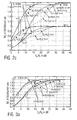
- Fig. 2a shows the one per set capacity for two transmit antennas in a frequency flat channel with Gaussian transmit symbols.
- cyclic delays yield the same capacity except for a cyclic delay of 32, which shows a slight degradation.
- this effect vanishes.
- cyclic delay diversity almost achieves the channel capacity for two transmit antennas and shows a significant diversity advantage over a single transmit antenna system.
- For two receive antennas there is still a clear diversity gain over a single transmit antenna system.
- transfer diversity schemes cannot reach the channel capacity in case of multiple receive antennas, there is a degradation compared to the channel capacity for two transmit antennas, which results from the different asymptotic slopes of the capacity curves.
- Fig. 3b demonstrates the performance for frequency selective channels for two transmit antennas, where all cyclic delays, which meet ⁇ 2 greater than D shows similar performance.
- Fig. 3b also demonstrates that cyclic delays need to be chosen larger than the maximum channel delay. Otherwise, the effective time-domain channel will include non-resolvable taps , which consist of sums of taps from different transmit antennas resulting in reduced diversity level.
- the present invention further provides a transmit apparatus comprising a processor for processing an information sequence using a processing scheme to obtain an input sequence and the apparatus for generating a plurality of output sequences from the input sequence to obtain cyclic diversity, as has been described above.
- the apparatus for generating the plurality of output sequences to be transmitted by a plurality of transmit points, each transmit point including a transmit antenna comprises a controller for controlling the cyclic shift element in order to adapt a number of values a copy of the cyclic shift element is to be shifted by to the processing scheme.
- the processing scheme may comprise any of the transmission conditions mentioned above.
- the processor comprises a coder for encoding the information sequence using a coding scheme
- the controller comprises by the apparatus for generating the plurality of output sequences (e.g. the controller 107) is configured for controlling the number of values a copy of the input sequence is to be shifted by for adapting the cyclic delay diversity to the coding scheme as has been described above.
- the coding scheme is associated with a code rate.
- the controller may be configured for controlling the number of values a copy of the input sequence is to be shifted in dependence on the code rate.
- the controller may configured for controlling the coder in order to e.g.
- the controller may be configured for determining the number of values in dependence on the coding scheme in order to e.g. take the code rate into account when introducing additional frequency diversity by the means of cyclically delaying the copies of the input sequence, as has been described above.
- the controller may refer to any known approaches providing an appropriate coding scheme for a given channel state.
- the controller may be configured for determining a code rate R in dependence on a number S of different channel states being introduced by the cyclic delay diversity scheme.
- the controller may be configured for determining R such that the following requirement is fulfilled: R ⁇ S - 1 S
- the transmit apparatus may comprise an assigner for assigning a number of successive symbols of each stream of symbols to a different set of successive sub-carriers in order to obtain a multi-carrier signal in frequency domain.
- the transmitter may comprise a frequency time transformer, e.g. an inverse Fourier transformer, for transforming the multi-carrier signal to obtain the input sequence, serving as a basis for providing the plurality of output sequences by the inventive apparatus for generating the plurality of output sequences.
- the controller comprised by the apparatus for generating the plurality of transmit sequences (output sequences) may be configured for providing the control signal to the de-multiplexer indicating the number of streams of values to be provided, wherein the number of streams of values depends on the coding scheme.
- the number of stream of values is closely related to a code rate resulting when using a certain code scheme and corresponds to e.g. a code word length.
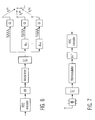
- FIG. 4 An embodiment of a transmitter apparatus incorporating the above-mentioned inventive concept is shown in Fig. 4 .
- FEC Forward Error Correction
- the switch 409 has a number of outputs, the number of outputs corresponding to the number of streams S mentioned above, wherein each output is associated with a signal processing path of S signal processing path.
- Each signalprocessing path comprises an interleaver 411 coupled between the respective output of the switch 409 and a mapper 413.
- Each mapper 413 has an output, wherein the S output of the mapper 413 is coupled to an assigner 415.
- the IFFT transformer has an output coupled to an input of the inventive apparatus 419 for generating the plurality of output sequences (transmit sequences).
- the inventive apparatus 419 comprises a copier for providing a plurality of copies of the input sequence provided by the IFFT transformer 419, wherein, the copier is represented by a node. Except for a first copy of the input sequence, all other copies of the input sequence are shifted using a controllable cyclic shift element 421 being comprised by the inventive apparatus 419.
- Each output sequence is provided to a guard insertion interval 423 (GI) in order to insert a guard interval, for example, a cyclic prefix according to an OFDM transmission scheme.
- GI guard insertion interval 423
- Each guard interval element 423 is associated with an antenna, as is depicted in Fig. 4 for the sake of completeness.
- the apparatus shown in Fig. 4 further comprises a rate adaptation unit 425, the rate adaptation unit 425 comprising the functionality of the inventive controller being described above.
- the rate adaptation unit 425 may be configured for controlling the encoder 405 in order to determine a coding scheme to be used by the encoder 405, the coding scheme being associated with a code rate R , and/or for controlling the switch 409 in order to determine the number of streams S , and/or for controlling the cyclic delays, i.e. the number of values the copies of the input sequence are to be shifted by.
- the encoder 402 may be configured for generating a control signal for controlling the encoder 401 and/or for controlling the switch 409 and/or for controlling the cyclic delay elements 421 in dependence on a transmission condition comprising e.g. a general state information (CSI), quality of service (QOS) or other transmission conditions, wherein the transmission condition may be provided to the rate adaptation unit 425 via a control input 427 from a further control entity comprised by the inventive transmitter, the further entity being configured e.g. for controlling the whole transmission process.
- CSI general state information
- QOS quality of service
- the information bits are encoded by the encoder of a forward error control (FEC) code.
- the code bits are de-multiplexed into S streams.
- optional interleaving is performed by a set of bit-interleavers ⁇ ( s ) .
- the interleaved code bits are mapped on transmit symbols according to the mapping rule of a digital modulation scheme, e.g. QAM, PSK, or a differential modulation scheme.
- the transmit symbols are mapped on sub-carriers of a multi-carrier modulation scheme such as OFDM by the sub-carrier assignment unit ⁇ f .
- the OFDM modulation is performed by the inverse fast Fourier transform (IFFT).
- IFFT inverse fast Fourier transform
- the code rate R is determined from a rate adaptation unit based on criteria such as current channel state or required quality of service.
- the rate adaptation unit also determines the cyclic delays ⁇ n and the number S of interleaver streams. For the choice of the cyclic delay and S , there are three modes:
- the cyclic delays are chosen independent of the code rate.
- the cyclic delays are chosen independent of the code rate.
- a more relaxed condition is that not all ⁇ n are relatively prime but at least some of them.
- the cyclic delays are chosen depending on the code rate R . Particularly, cyclic delays are chosen such that the equivalent frequency domain channel will have S different states given that the original channel was frequency flat. The value of S is obtained from Fig. 5 .
- the rate adaptation unit chooses the code rate depending on a criterion such as channel state or QoS. Depending on the code rate it chooses the smallest value of S from Fig. 5 , which is possible for the given number n T of transmit antennas.
- the cyclic delays are determined such that S different channel states would result in a flat fading channel.
- the interleaving scheme is also modified such that the code bits are de-multiplexed into S streams.
- Each stream performs optional interleaving according to the permutation rules ⁇ ( s ) .
- the permuted bits are mapped on complex constellation elements of a digital modulation method such as QAM or PSK. Differential modulation is also possible in each stream.
- the transmit symbols are mapped on sub-carriers by the sub-carrier assignment unit ⁇ f . This is done such that the symbols of a particular stream s are assigned to sub-carriers, which would face the same channel state in a flat fading channel. This is accomplished as indicated in Fig. 9 , where the symbols of the S streams are assigned to S neighbouring sub-carriers. Additional frequency interleaving of groups of size S is possible.
- the receiver is informed about the current code rate and the number of streams. Essentially, it is sufficient if the receiver is informed about the code rate R . From the code rate it can determine the cyclic delays from a look-up table, which is stored in the receiver.
- the receiver performs the reverse operation of the transmitter: After the FFT, a demapping unit demaps the received symbols to bits. Preferably, soft values, e.g. log-likelihood ratios are computed. These output values of the demapper are deinter-leaved in each of the S streams.
- the S streams are multiplexed and fed to the FEC decoder.
- cyclic delay diversity can also be introduced at the receiver in order to increase a frequency selectivity of a resulting effective channel.
- the present invention further provides an apparatus for generating an output sequence from a plurality of input sequences, for example from n T input sequences, for obtaining cyclic delay diversity.
- the plurality of input sequences may be associated with the plurality of receiving points, each receiving point comprising a receive antenna, the receiving points being configured for providing different receive versions of a transmit sequence being transmitted through a communication channel.
- the inventive apparatus comprises n T -1 cyclic shift elements for variably cyclically shifting T input sequences to obtain n T -1 shifted sequences, wherein each cyclic shift element is configured for receiving a variable control signal indicating a number of values an input sequence is to be shifted by, and, in response to the variable control signal, for cyclically shifting the input sequence by the number of values. Furthermore, the apparatus comprises an adder for adding the n T -1 shifted sequences and a first input sequence or a shifted version thereof to obtain the output sequence.
- the apparatus for generating the output sequence may comprise a controller having the functionalities described above for controlling the shift elements in order to adjust the cyclic delay diversity depending e.g. on a transmission condition, as has been described above.
- the apparatus for generating the output sequence may be used in a receiver, for example, in a multi-carrier receiver having been configured e.g. for receiving signals being provided by the inventive transmit apparatus described above.
- the receiver comprises a functionality, which is inverse to that of the transmit apparatus described above.
- the present invention further provides a receiver apparatus for providing a received version of an information sequence from a receive sequence, the receive sequence comprising a superposition of a plurality of transmit sequences being transmitted through the plurality of communication channels, a transmit sequence resulting from cyclically shifting a copy of an input sequence by a number of values, the input sequence resulting from frequency-time transforming a multi-carrier signal, the multi-carrier signal comprising different sets of successive sub-carriers, each set of successive sub-carriers resulting from assigning a number of successive symbols of a stream of symbols of a number of streams of symbols to successive sub-carriers, a stream of symbols resulting from mapping groups of streams of values onto symbols according to a mapping scheme, e.g.
- the receive sequence is a received version of a transmit sequence being generated by the inventive transmit apparatus described above.
- the receive apparatus comprises means for providing information on the coding scheme in order to reprocess the received sequence using an inverse processing scheme to that used at the transmitter.
- the receive apparatus comprises a time-frequency transformer, for example a Fourier transformer, for transforming the receive sequence into a transformed sequence.
- a time-frequency transformer for example a Fourier transformer
- the receive apparatus comprises a reassigner being coupled to a plurality of outputs of the time-frequency transformer, the reassigner being configured for performing an operation which is inverse to the operation of the assigner 415 shown in Fig. 4 .
- the reassigner has S outputs, each output being coupled to a demapper, each demapper being coupled to a deinterleaver.
- the demapper and the interleaver are configured for performing inverse operations to those performed by the mapper 413 and interleaver 411 shown in Fig. 4 , by way of example only. It is to be noted that the interleaver 411 and the deinterleaver are optional.
- the S outputs of the S demapper are coupled to a multiplexer being configured for multiplexing the data to a sequence to be decoded by a decoder in order to obtain the received version of the information sequence.
- the means for providing information on the coding scheme may be configured for deriving the number of streams S from the coding scheme and for controlling the reassigner 415 in order to obtain the S streams to be demapped.
- the receive apparatus may comprise a channel estimator being configured for estimating the plurality of channels from an estimate of the effective channel.
- the channel estimator may require information on currently being used cyclic delays. This information can be provided by the means for providing the information on the coding scheme. More specifically, the means for providing information on the coding scheme may be configured for deriving the number S from the code rate and to derive the used cyclic delays using the number S, by way of example only.
- the capacity of cyclic delay diversity can be computed from the frequency domain representation (5) of the equivalent frequency-selective single-input multiple-output (SIMO) channel.
- SIMO single-input multiple-output
- the x% outage capacity C x is the capacity, which is guaranteed in (100-x)% of the channel realizations, i.e. we expect an outage of x%.
- the code rates and modulation formats will be chosen adaptively, depending on criteria like current channel state or quality of service (QoS) requirements.
- QoS quality of service
- the present invention provides, therefore, an adaptive cyclic delay diversity scheme, which uses the optimum cyclic delay according to e.g. a current code rate.
- inventive interleaving scheme can also be adapted in order to provide full spatial diversity.
- the present invention further provides modes where cyclic delay may be chosen independently of the code rate such that the scheme is optimum in terms of capacity for all code rates.
- cyclic delay is chosen depending on a code rate of the FEC code.
- the inventive scheme transforms the spatial diversity into frequency diversity between a minimum number of neighbouring sub-carriers, which is optimum for a current code rate. This will yield optimum FER performance in systems with adaptive coding using codes of limited constraint length.
- the inventive cyclic delay diversity scheme enables exploiting spatial diversity in a coded OFDM system without increasing the receiver's complexity compared to a single antenna system. Moreover, guard interval need not to be exceeded. Furthermore, adaptive code rates are supported by adapting the cyclic delays to the chosen code rates such that the optimum cyclic delays for each code rate are chosen. Additionally, differential modulation in frequency domain is supported by the proposed adaptive choice of the cyclic delays.
- the present invention further provides a transmitter apparatus a plurality of transmit sequences, comprising an encoder for encoding an information sequence using a coding scheme to obtain an encoded sequence, a de-multiplexer for de-multiplexing the encoded sequence into a number of streams of values in response to a control signal indicating the number of streams of values, for a stream of values, preferably for each stream of values, a mapper for mapping groups of stream values onto symbols according to a mapping scheme to obtain the number of streams of symbols, an assigner for assigning a number of successive symbols for each stream of symbols to a different set of successive sub-carriers to obtain a multicarrier sequence, a copier for providing a number of copies of the multi carrier sequence, for a copy of the multicarrier sequence, a variable phase shift element for introducing a variable phase shift into a copy of the multicarrier sequence to obtain a phase shifted copy of the multicarrier sequence, for a phase shifted copy of the multicarrier sequence, a frequency time transformer to obtain a
- controller may be configured for providing a control signal indicating the number of copies of the multi carrier signal, and wherein the copier is configured for generating the number of copies of the multi carrier signal in response to the control signal.
- each transmit sequence of the plurality of transmit sequences is to be transmitted by a different transmitting point including e.g. a transmit antenna, of a number of transmitting points, the number of transmitting points being equal to the number of transmit sequences. Therefore, the apparatus may comprise the number of transmitting points for transmitting the transmit sequences.
- the apparatus comprises a number of phase shift elements being equal to or less than the number of copies of the multicarrier sequence.
- a first transmit sequence may correspond to an unshifted version of the multicarrier sequence.
- the number of phase shift elements is smaller than the number of copies of the multicarrier sequence.
- the number of phase shift elements may be equal to the number of copies of the multicarrier sequence for introducing a phase shift into each copy of the multicarrier sequence.
- the transmit apparatus comprises the full functionality of the apparatus described with respect to Fig. 4 .
- the encoder, the demultiplexer, the mapper, the assigner and the controller comprise the functionalities of the corresponding elements being described above, e.g. with respect to the corresponding elements being described with respect to Fig. 4 .
- the apparatus is configured for introducing the frequency diversity by the means of phase shifting, wherein the variable phase shifts correspond to the variable cyclic delays described above. Since a cyclic delay in time domain introduces a certain phase shift in frequency domain, the inventive variable cyclic delay diversity scheme may be replaced by a variable phase shift scheme, wherein the variable phase shifts are frequency domain representations of the cyclic shifts described above.
- the inventive methods can be implemented in hardware or in software.
- the implementation can be performed using a digital storage medium, in particular a disk or a CD having electronically readable control signals stored thereon, which can cooperate with a programmable computer system such that the inventive methods are performed.
- the present invention is, therefore, a computer program product with a program code stored on a machine-readable carrier, the program code being configured for performing at least one of the inventive methods, when the computer program products runs on a computer.
- the inventive methods are, therefore, a computer program having a program code for performing the inventive methods, when the computer program runs on a computer.
Landscapes
- Engineering & Computer Science (AREA)
- Computer Networks & Wireless Communication (AREA)
- Signal Processing (AREA)
- Radio Transmission System (AREA)
Claims (20)
- Vorrichtung zum Erzeugen einer Mehrzahl von Ausgangssequenzen aus einer Eingangssequenz zum Erhalten einer zyklischen Verzögerungsdiversität, wobei die Vorrichtung folgende Merkmale aufweist:einen Kopierer (101) zum Liefern einer Mehrzahl von Kopien der Eingangssequenz;ein zyklisches Schiebeelement (107) zum variablen zyklischen Schieben einer Kopie der Eingangssequenz, um eine Ausgangssequenz der Mehrzahl von Ausgangssequenzen zu erhalten, wobeidas zyklische Schiebeelement (107) konfiguriert ist, um ein variables Steuersignal zu empfangen, das eine Anzahl von Werten anzeigt, um die die Kopie der Eingangssequenz verschoben werden soll, und ansprechend auf das variable Steuersignal, zum zyklischen Verschieben der Kopie der Eingangssequenz um die Anzahl von Werten,wobei die Mehrzahl von Ausgangssequenzen durch eine Mehrzahl von Sendepunkten durch die Mehrzahl von variierenden Kanälen gesendet werden soll, wobei die Vorrichtung eine Steuerung (111) aufweist, die zum Erzeugen des variablen Steuersignals konfiguriert ist, um die zyklische Verzögerungsdiversität an eine variable Sendebedingung anzupassen,wobei die variable Sendebedingung eine Coderate aufweist, wobei die Steuerung (111) konfiguriert ist, um eine Anzahl von Werten zu bestimmen, um die die Kopie der Eingangssequenz verschoben werden soll, abhängig von der Coderate.
- Vorrichtung gemäß Anspruch 1, bei der die variable Sendebedingung einen Diversitätscodierungsgewinn oder ein Codierungsschema oder eine Kapazität eines Kanals oder Kanalzustandsinformationen oder eine Kapazität eines effektiven Kanals die resultiert, wenn eine zyklische Verzögerungsdiversität eingebracht wird, oder eine Bitfehlerrate oder eine verfügbare Bandbreite oder eine Anzahl von Benutzersignalen, die in der Eingangssequenz bei einem Mehrbenutzerszenario enthalten sind, oder eine Anzahl von Sendepunkten oder eine Anzahl von Empfangspunkten oder ein Modulations- oder ein Demodulations-Schema oder eine Dienstqualitätsanforderung oder eine Länge der Eingangssequenz aufweist.
- Vorrichtung gemäß Anspruch 1 oder 2, bei der die variable Sendebedingung unterschiedliche Coderaten aufweist, wobei die Steuerung (111) konfiguriert ist zum Bestimmen der Anzahl von Werten, um die die Kopie der Eingangssequenz verschoben werden soll, abhängig von einer Coderatenoberbegrenzung unterschiedlicher Coderaten.
- Vorrichtung gemäß einem der Ansprüche 1 bis 3, bei der die Steuerung (111) zum Bestimmen einer Anzahl von Werten konfiguriert ist, um die die Kopie der Eingangssequenz verschoben werden soll, aus einer Nachschlagtabelle, die unterschiedliche Zahlen von Werten für unterschiedliche Coderaten aufweist.
- Vorrichtung gemäß einem der Ansprüche 1 bis 4, bei der die Eingangssequenz aus der Verarbeitung einer Informationssequenz resultiert, wobei die Informationssequenz unter Verwendung eines Codierungsschemas codiert ist, wobei die variable Sendebedingung eine Coderate R ist, die dem Codierungsschema zugeordnet ist, wobei die Steuerung (111) zum Bestimmen der Anzahl von Werten konfiguriert ist, derart, dass eine Anzahl unterschiedlicher Kanalzustände in einen effektiven Kanal eingebracht ist, wobei der effektive Kanal resultiert, wenn die Mehrzahl von Ausgangssequenzen durch die Mehrzahl von Kommunikationskanälen übertragen werden, wobei die Anzahl unterschiedlicher Kanalzustände S derart ausgewählt ist, dass die nachfolgende Anforderung erfüllt ist.

- Vorrichtung gemäß Anspruch 5, bei der die Anzahl von Kanalzuständen eine Anzahl unterschiedlicher Sätze aus korrelierten Koeffizienten einer Übertragungsfunktion des effektiven Kanals bestimmt, wobei Koeffizienten, die zu unterschiedlichen Sätzen gehören, zumindest teilweise unkorreliert sind.
- Vorrichtung gemäß einem der Ansprüche 1 bis 6, bei der die Eingangssequenz eine Mehrfachträgersequenz aufweist, die Frequenz-Zeit transformiert ist, unter Verwendung einer NS-Punkt-Frequenz-Zeit-Transformation, wobei die Mehrfachträgersequenz aus einer Informationssequenz erhalten wird, die unter Verwendung eines Codierungsschemas codiert ist, wobei die Vorrichtung eine Steuerung zum Erzeugen des variablen Steuerungssignals aufweist, das eine Anzahl von Werten anzeigt, um die eine n-te Kopie der Eingangssequenz verschoben werden soll, wobei die Anzahl aus Werten aus der folgenden Gleichung hergeleitet werden kann:

- Vorrichtung gemäß einem der Ansprüche 1 bis 7, bei der die variable Sendebedingung eine Kapazität eines effektiven Kanals aufweist, wobei der effektive Kanal resultiert, wenn die Mehrzahl von Ausgangssequenzen durch die Mehrzahl von Kanälen transformiert wird, wobei die Kapazität des effektiven Kanals von einer Anzahl von Werten abhängt, um die eine Kopie der Eingangssequenz verschoben werden soll, wobei die Steuerung konfiguriert ist, um die Anzahl von Werten derart zu bestimmen, dass die Kapazität des effektiven Kanals erhöht wird.
- Vorrichtung gemäß Anspruch 8, bei der die Steuerung konfiguriert ist, um die Anzahl von Werten nur aus einem Satz von Werten zu bestimmen, die Werte aufweisen, die einen größten gemeinsamen Teiler gleich Eins aufweisen.
- Vorrichtung gemäß einem der Ansprüche 1 bis 9, wobei die Vorrichtung eine Steuerung aufweist, wobei die Steuerung konfiguriert ist, um die Anzahl von Werten auf der Basis von Kanalzustandsinformationen zu bestimmen, um die zyklische Verschiebung der Kopie der Eingangssequenz abhängig von den Kanalzustandsinformationen zu steuern.
- Sendervorrichtung, die folgende Merkmale aufweist:einen Prozessor zum Verarbeiten einer Informationssequenz unter Verwendung eines Verarbeitungsschemas, um eine Eingangssequenz zu erhalten;die Vorrichtung gemäß einem der Ansprüche 1 bis 10 zum Erzeugen einer Mehrzahl von Ausgangssequenzen aus der Eingangssequenz, um eine zyklische Verzögerungsdiversität zu erhalten, wobei die Mehrzahl von Ausgangssequenzen durch eine Mehrzahl von Sendepunkten gesendet werden soll, wobei die Vorrichtung zum Erzeugen der Mehrzahl von Ausgangssequenzen eine Steuerung zum Steuern des zyklischen Schiebeelements aufweist, um die Anzahl von Werten, um die eine Kopie der Eingangssequenz verschoben werden soll, an das Verarbeitungsschema anzupassen.
- Sendervorrichtung gemäß Anspruch 11, bei der der Prozessor einen Codierer zum Codieren der Informationssequenz unter Verwendung eines Codierungsschemas aufweist, wobei die Steuerung zum Steuern der Anzahl von Werten konfiguriert ist, um die eine Kopie der Eingangssequenz verschoben werden soll, zum Anpassen der zyklischen Verzögerungsdiversität an das Codierungsschema.
- Sendervorrichtung gemäß Anspruch 12, bei der das Codierungsschema einer Coderate zugeordnet ist, wobei die Steuerung konfiguriert ist, um die Anzahl von Werten zu steuern, um die eine Kopie der Eingangssequenz verschoben werden soll, abhängig von der Coderate.
- Sendervorrichtung gemäß Anspruch 12 oder 13, bei der die Steuerung konfiguriert ist, um das Codierungsschema abhängig von einer Sendebedingung zu bestimmen, und um die Anzahl von Werten abhängig von dem Codierungsschema zu bestimmen.
- Sendervorrichtung gemäß einem der Ansprüche 11 bis 14, bei der der Prozessor folgende Merkmale aufweist:einen Codierer zum Codieren der Informationssequenz unter Verwendung eines Codierungsschemas, um eine codierte Sequenz zu erhalten;einen Demultiplexer zum Demultiplexen der codierten Sequenz in eine Anzahl von Strömen von Werten ansprechend auf ein Steuersignal, das die Anzahl von Strömen von Werten anzeigt;für jeden Strom aus Werten, eine Abbildungseinrichtung zum Abbilden von Gruppen aus Stromwerten auf Symbole gemäß einem Abbildungsschema, um die Anzahl von Strömen von Symbolen zu erhalten;eine Zuordnungseinrichtung zum Zuordnen einer Anzahl von aufeinander folgenden Symbolen jedes Stroms aus Symbolen zu einem unterschiedlichen Satz aus aufeinander folgenden Teilträgern, um ein Mehrfachträgersignal zu erhalten;einen Frequenz-Zeit-Transformator, um das Mehrfachträgersignal zu transformieren, um die Eingangssequenz zu erhalten;wobei die Steuerung konfiguriert ist, um das Steuersignal zu liefern, das die Anzahl von Strömen von Werten anzeigt, wobei die Anzahl von Strömen von Werten von dem Codierungsschema abhängt.
- Vorrichtung zum Erzeugen einer Ausgangssequenz aus nT Eingangssequenzen zum Erhalten einer zyklischen Verzögerungsdiversität, wobei die Eingangssequenzen durch eine Mehrzahl von Empfangpunkten durch eine Mehrzahl von variierenden Kanälen empfangen werden, wobei die Vorrichtung folgende Merkmale aufweist:eine Steuerung, die zum Erzeugen eines variablen Steuersignals konfiguriert ist, um die zyklische Verzögerungsdiversität an eine variable Sendebedingung anzupassen, wobei die variable Sendebedingung eine Coderate aufweist, wobei die Steuerung konfiguriert ist, um eine Anzahl von Werten zu bestimmen, um die die Kopie der Eingangssequenzen verschoben werden soll, abhängig von der Coderate;nT-1 zyklische Schiebeelemente zum variablen zyklischen Verschieben von nT-1 Eingangssequenzen, um nT-1 verschobene Sequenzen zu erhalten, wobei jedes zyklische Schiebeelement konfiguriert ist, um das variable Steuersignal zu empfangen, das eine Anzahl von Werten anzeigt, um die eine Eingangssequenz verschoben werden soll, und, ansprechend auf das variable Steuersignal, zum zyklischen Verschieben der Eingangssequenz um die Anzahl von Werten; undeinen Addierer zum Addieren der nT-1 verschobenen Sequenzen und einer ersten Eingangssequenz oder einer verschobenen Version derselben, um die Ausgangssequenz zu erhalten.
- Verfahren zum Erzeugen einer Mehrzahl von Ausgangssequenzen aus einer Eingangssequenz, um eine zyklische Verzögerungsdiversität zu erhalten, wobei die Mehrzahl von Ausgangssequenzen durch eine Mehrzahl von Sendepunkten durch eine Mehrzahl variierender Kanäle gesendet werden soll, wobei das Verfahren folgende Schritte aufweist:Bereitstellen einer Mehrzahl von Kopien der Eingangssequenz;Erzeugen eines variablen Steuersignals, um die zyklische Verzögerungsdiversität an eine variable Sendebedingung anzupassen, wobei die variable Sendebedingung eine Coderate aufweist,wobei der Schritt des Erzeugens den Schritt des Bestimmens einer Anzahl von Werten aufweist, um die die Kopie der Eingangssequenz verschoben werden soll, abhängig von der Coderate; undvariables, zyklisches Verschieben einer Kopie der Eingangssequenz, um eine Ausgangssequenz der Mehrzahl von Ausgangssequenzen auf das Empfangen des variablen Steuersignals hin zu erhalten, das eine Anzahl von Werten anzeigt, um die die Kopie der Eingangssequenz verschoben werden soll, und, ansprechend auf das variable Steuersignal, zum zyklischen Verschieben der Kopie der Eingangssequenz um die Anzahl von Werten.
- Verfahren, das folgende Schritte aufweist:Verarbeiten einer Informationssequenz unter Verwendung eines Verarbeitungsschemas, um eine Eingangssequenz zu erhalten;Erzeugen einer Mehrzahl von Ausgangssequenzen aus der Eingangssequenz gemäß dem Verfahren von Anspruch 17;Steuern der zyklischen Verschiebung einer Kopie der Eingangssequenz, um eine Anzahl von Werten, um die eine Kopie der Eingangssequenz verschoben werden soll, an das Verarbeitungsschema anzupassen.
- Verfahren zum Erzeugen einer Ausgangssequenz aus nT Eingangssequenzen, um eine zyklische Verzögerungsdiversität zu erhalten, wobei die Eingangssequenzen durch eine Mehrzahl von Empfangspunkten durch eine Mehrzahl von variierenden Kanälen empfangen werden, wobei das Verfahren folgende Schritte aufweist:Erzeugen eines variablen Steuersignals, um die zyklische Verzögerungsdiversität an eine variable Empfangsbedingung anzupassen, wobei die variable Sendebedingung eine Coderate aufweist, wobei der Schritt des Erzeugens das Bestimmen einer Anzahl von Werten aufweist, um die die Kopie der Eingangssequenzen verschoben werden soll, abhängig von der Coderate;Empfangen des variablen Steuersignals, das eine Anzahl von Werten anzeigt, um die eine Eingangssequenz verschoben werden soll, und ansprechend auf das variable Steuersignal, variables zyklisches Verschieben von nT-1 Eingangssequenzen, um nT verschobene Sequenzen zu erhalten; undAddieren der nT-1 verschobenen Sequenzen und einer ersten Eingangssequenz oder einer verschobenen Version derselben, um die Ausgangssequenz zu erhalten.
- Computerprogramm, das eine Programmeinrichtung zum Ausführen der Schritte von zumindest einem der Verfahren von Anspruch 17 bis 19 aufweist, wenn das Computerprogramm auf einem Computer ausgeführt wird.
Applications Claiming Priority (1)
| Application Number | Priority Date | Filing Date | Title |
|---|---|---|---|
| PCT/EP2004/009595 WO2006021227A1 (en) | 2004-08-27 | 2004-08-27 | Apparatus and method for obtaining delay diversity |
Publications (2)
| Publication Number | Publication Date |
|---|---|
| EP1782553A1 EP1782553A1 (de) | 2007-05-09 |
| EP1782553B1 true EP1782553B1 (de) | 2009-05-13 |
Family
ID=34958581
Family Applications (1)
| Application Number | Title | Priority Date | Filing Date |
|---|---|---|---|
| EP04764569A Expired - Fee Related EP1782553B1 (de) | 2004-08-27 | 2004-08-27 | Vorrichtung und verfahren zum erhalten von verzögerungs-diversity |
Country Status (4)
| Country | Link |
|---|---|
| EP (1) | EP1782553B1 (de) |
| JP (1) | JP4195073B2 (de) |
| DE (1) | DE602004021143D1 (de) |
| WO (1) | WO2006021227A1 (de) |
Families Citing this family (10)
| Publication number | Priority date | Publication date | Assignee | Title |
|---|---|---|---|---|
| DE602004012460T2 (de) * | 2004-08-27 | 2009-03-12 | Ntt Docomo Inc. | Vorrichtung und verfahren zum erhalten von cyclischer verzögerungs-diversity |
| JP4978384B2 (ja) | 2006-10-31 | 2012-07-18 | 日本電気株式会社 | 移動通信システム、送信装置、および送信信号生成方法 |
| JP2008118650A (ja) * | 2006-10-31 | 2008-05-22 | Ntt Docomo Inc | 循環遅延ダイバーシティ遅延値の確定方法、システム、基地局及びue |
| US8780771B2 (en) * | 2007-02-06 | 2014-07-15 | Qualcomm Incorporated | Cyclic delay diversity and precoding for wireless communication |
| US8509710B2 (en) | 2007-02-06 | 2013-08-13 | Qualcomm Incorporated | MIMO transmission with explicit and implicit cyclic delays |
| CN101282198B (zh) * | 2007-04-05 | 2012-03-28 | 电信科学技术研究院 | 一种时分双工tdd系统中的上行多天线传输方法及终端 |
| GB2449858B (en) * | 2007-06-04 | 2012-10-17 | British Broadcasting Corp | Delay diversity transmission apparatus and method |
| US8325852B2 (en) * | 2007-06-08 | 2012-12-04 | Samsung Electronics Co., Ltd. | CDD precoding for open loop SU MIMO |
| WO2009089656A1 (fr) | 2008-01-17 | 2009-07-23 | Alcatel Shanghai Bell Company, Ltd. | Procédé et appareil pour effectuer une mise en correspondance de retard cyclique avec le signal dans un émetteur doté de multiples antennes |
| JP5031670B2 (ja) * | 2008-06-02 | 2012-09-19 | 株式会社日立製作所 | 送信装置、基地局及びシンボル送信方法 |
Family Cites Families (4)
| Publication number | Priority date | Publication date | Assignee | Title |
|---|---|---|---|---|
| US6377632B1 (en) * | 2000-01-24 | 2002-04-23 | Iospan Wireless, Inc. | Wireless communication system and method using stochastic space-time/frequency division multiplexing |
| US6842487B1 (en) * | 2000-09-22 | 2005-01-11 | Telefonaktiebolaget Lm Ericsson (Publ) | Cyclic delay diversity for mitigating intersymbol interference in OFDM systems |
| JP3679075B2 (ja) * | 2002-09-13 | 2005-08-03 | 松下電器産業株式会社 | 無線送信装置および無線送信方法 |
| US20040087294A1 (en) * | 2002-11-04 | 2004-05-06 | Tia Mobile, Inc. | Phases array communication system utilizing variable frequency oscillator and delay line network for phase shift compensation |
-
2004
- 2004-08-27 EP EP04764569A patent/EP1782553B1/de not_active Expired - Fee Related
- 2004-08-27 WO PCT/EP2004/009595 patent/WO2006021227A1/en active Application Filing
- 2004-08-27 DE DE602004021143T patent/DE602004021143D1/de active Active
- 2004-08-27 JP JP2007528607A patent/JP4195073B2/ja not_active Expired - Fee Related
Also Published As
| Publication number | Publication date |
|---|---|
| EP1782553A1 (de) | 2007-05-09 |
| JP2008511220A (ja) | 2008-04-10 |
| WO2006021227A1 (en) | 2006-03-02 |
| JP4195073B2 (ja) | 2008-12-10 |
| DE602004021143D1 (de) | 2009-06-25 |
Similar Documents
| Publication | Publication Date | Title |
|---|---|---|
| Ma et al. | Full-diversity full-rate complex-field space-time coding | |
| US7430243B2 (en) | Space-time-frequency coded OFDM communications over frequency-selective fading channels | |
| CN100403808C (zh) | 多信道通信系统的速率控制 | |
| JP3962020B2 (ja) | 直交周波数分割多重方式の移動通信システムにおける時空間−周波数符号化/復号化装置及び方法 | |
| EP1628426B1 (de) | Vorrichtung und Verfahren zur Leistungsverbesserung von Raum-Zeit-Frequenz Blockkodierungen | |
| US7280604B2 (en) | Space-time doppler coding schemes for time-selective wireless communication channels | |
| KR101280734B1 (ko) | Mimo 통신 시스템에서의 증분 리던던시 송신 | |
| US20060146692A1 (en) | Methods and apparatus for mitigating multi-antenna correlation effect in communication systems | |
| JP5619146B2 (ja) | Su−mimoシステムのための受信端末駆動型エンコーダ/デコーダモード同時適応 | |
| JP2005510126A6 (ja) | 直交周波数分割多重方式の移動通信システムにおける時空間−周波数符号化/復号化装置及び方法 | |
| WO2006049426A1 (en) | Apparatus and method for transmitting and receiving data using space-time block coding | |
| EP1747632A1 (de) | Raum-zeit-blockcodierung in orthogonal-frequenzmultiplex-kommunikationssystemen | |
| KR100849338B1 (ko) | 직교주파수분할다중 방식의 이동통신시스템에서시공간-주파수 부호화/복호화 장치 및 방법 | |
| EP1573936B1 (de) | Vorrichtung und verfahren zur zyklischen verzögerungsdiversität | |
| EP1782553B1 (de) | Vorrichtung und verfahren zum erhalten von verzögerungs-diversity | |
| US8139668B2 (en) | Unified STTC encoder for WAVE transceivers | |
| KR100866195B1 (ko) | 직교주파수분할다중 방식의 이동통신시스템에서 시공간-주파수 부호화/복호화 장치 및 방법 | |
| WO2007111198A1 (ja) | 送信方法及び送信装置 | |
| EP1661346B1 (de) | Vorrichtung und verfahren zur bereitstellung eines zu sendenden mehrträgersignals und vorrichtung und verfahren zur bereitstellung eines ausgangssignals aus einem empfangenen mehrträgersignal | |
| EP1782565B1 (de) | Vorrichtung und verfahren zum erhalten von cyclischer verzögerungs-diversity | |
| RU2419212C2 (ru) | Способ преобразования уровней и способ передачи данных для системы mimo | |
| WO2008130102A1 (en) | Close loop transmission method and apparatus | |
| Zeydan et al. | Differential space-frequency group codes for MIMO-OFDM | |
| Bandyopadhyay et al. | Joint optimal pilot placement and space frequency (SF) code design for MIMO-OFDM systems | |
| Kumaratharan et al. | Performance Improvement of ICE for Orthogonal STBC MC-CDMA Systems over MIMO Channels |
Legal Events
| Date | Code | Title | Description |
|---|---|---|---|
| PUAI | Public reference made under article 153(3) epc to a published international application that has entered the european phase |
Free format text: ORIGINAL CODE: 0009012 |
|
| 17P | Request for examination filed |
Effective date: 20070102 |
|
| AK | Designated contracting states |
Kind code of ref document: A1 Designated state(s): DE GB |
|
| DAX | Request for extension of the european patent (deleted) | ||
| RBV | Designated contracting states (corrected) |
Designated state(s): DE GB |
|
| GRAP | Despatch of communication of intention to grant a patent |
Free format text: ORIGINAL CODE: EPIDOSNIGR1 |
|
| GRAS | Grant fee paid |
Free format text: ORIGINAL CODE: EPIDOSNIGR3 |
|
| GRAA | (expected) grant |
Free format text: ORIGINAL CODE: 0009210 |
|
| AK | Designated contracting states |
Kind code of ref document: B1 Designated state(s): DE GB |
|
| REG | Reference to a national code |
Ref country code: GB Ref legal event code: FG4D |
|
| REF | Corresponds to: |
Ref document number: 602004021143 Country of ref document: DE Date of ref document: 20090625 Kind code of ref document: P |
|
| PLBE | No opposition filed within time limit |
Free format text: ORIGINAL CODE: 0009261 |
|
| STAA | Information on the status of an ep patent application or granted ep patent |
Free format text: STATUS: NO OPPOSITION FILED WITHIN TIME LIMIT |
|
| 26N | No opposition filed |
Effective date: 20100216 |
|
| PGFP | Annual fee paid to national office [announced via postgrant information from national office to epo] |
Ref country code: DE Payment date: 20130821 Year of fee payment: 10 |
|
| PGFP | Annual fee paid to national office [announced via postgrant information from national office to epo] |
Ref country code: GB Payment date: 20130821 Year of fee payment: 10 |
|
| REG | Reference to a national code |
Ref country code: DE Ref legal event code: R119 Ref document number: 602004021143 Country of ref document: DE |
|
| GBPC | Gb: european patent ceased through non-payment of renewal fee |
Effective date: 20140827 |
|
| REG | Reference to a national code |
Ref country code: DE Ref legal event code: R119 Ref document number: 602004021143 Country of ref document: DE Effective date: 20150303 |
|
| PG25 | Lapsed in a contracting state [announced via postgrant information from national office to epo] |
Ref country code: DE Free format text: LAPSE BECAUSE OF NON-PAYMENT OF DUE FEES Effective date: 20150303 Ref country code: GB Free format text: LAPSE BECAUSE OF NON-PAYMENT OF DUE FEES Effective date: 20140827 |