EP1782004B1 - Cooling cylinder for ice-flake making apparatus - Google Patents
Cooling cylinder for ice-flake making apparatus Download PDFInfo
- Publication number
- EP1782004B1 EP1782004B1 EP05752779A EP05752779A EP1782004B1 EP 1782004 B1 EP1782004 B1 EP 1782004B1 EP 05752779 A EP05752779 A EP 05752779A EP 05752779 A EP05752779 A EP 05752779A EP 1782004 B1 EP1782004 B1 EP 1782004B1
- Authority
- EP
- European Patent Office
- Prior art keywords
- jacket
- cylinder
- cylindrical body
- channel
- path
- Prior art date
- Legal status (The legal status is an assumption and is not a legal conclusion. Google has not performed a legal analysis and makes no representation as to the accuracy of the status listed.)
- Active
Links
Images


Classifications
-
- F—MECHANICAL ENGINEERING; LIGHTING; HEATING; WEAPONS; BLASTING
- F25—REFRIGERATION OR COOLING; COMBINED HEATING AND REFRIGERATION SYSTEMS; HEAT PUMP SYSTEMS; MANUFACTURE OR STORAGE OF ICE; LIQUEFACTION SOLIDIFICATION OF GASES
- F25C—PRODUCING, WORKING OR HANDLING ICE
- F25C1/00—Producing ice
- F25C1/12—Producing ice by freezing water on cooled surfaces, e.g. to form slabs
- F25C1/14—Producing ice by freezing water on cooled surfaces, e.g. to form slabs to form thin sheets which are removed by scraping or wedging, e.g. in the form of flakes
Definitions
- the invention relates to a cooling cylinder for forming ice flakes or granular ice according to the preamble of claim 1.
- a cooling cylinder is known for example from US-A-2001/0 045 275 .
- This type of ice which is widely used to keep at a low temperature food inside containers for display or transportation, is obtained by means of apparatus which use a cooling cylinder such as, for example, that forming the subject of Italian Utility Model No. 0216265 .
- the cylinder of these apparatus consists of a central body in the form of a tubular interspace which is closed at the ends by two flanges; the interspace has, arranged inside it, radial baffles which define a channel extending along the generatrices of the cylinder.
- the refrigerating fluid is made to evaporate inside the channel and thus cools the outer surface of the cylinder onto which the water is sprayed: the latter freezes and is scraped off in the form of flakes by a knife rotating about the cylinder.
- the Applicant is of the opinion that it is advantageous to increase the heat exchange of the refrigerating fluid with the cooling cylinder since in this way it is possible to increase the hourly production of ice, all other conditions being equal, such as for example the fluid and water flowrate, the dimensions of the cylinder, etc.
- the idea for solving this problem consists in providing a novel cooling cylinder in which the path along which the refrigerating fluid flows has a winding progression with coil-like sections, which are preferably short compared to the height of the cylinder, such that the turbulence of the flow and consequently also the heat exchange increases.
- the flow is obtained with a channel formed on the surface of the cylinder body, closed externally by a tubular jacket mounted on the aforementioned body.
- FIGS. 1-10 show an overall view of a cooling cylinder 10, according to the invention, which is intended to be used in combination with a compressor and a condenser, not shown in the drawings, in accordance with the usual operating principle of known refrigerating units.
- the cylinder 10 acts instead as an evaporator of the unit and comprises a central body 20 with a cylindrical geometry, to which a jacket 40 is joined externally; in accordance with a preferred embodiment, the cylindrical body 20 is made of high-impact strength steel (instead of aluminium) and the jacket 40 is welded onto it at the ends so as not to require seals for sealing thereof.
- cylindrical body 20 may be made of aluminium and the jacket 40 shrunk on it, while the seal between them is ensured by means of sealing gaskets.
- Respective flanges 80 and 81 are mounted on the top and bottom ends of the body 20, thus closing off the space inside them; these flanges are constrained together with isolating spacers 82 and 83 by means of bolts 84 and the upper flange has a neck 86 through which two pipes 22, 24 for entry and return, respectively, of a refrigerating fluid pass.
- a collar 87 is mounted on the outside of the neck 86 and is able to rotate on revolving bearings 88; a gear wheel 89 is fixed (by means of screws visible in Fig. 2 ) around the collar 87, while a scraper knife 90 projects radially therefrom; the knife has a series of comb-like blades 91 of the known type and is connected at the bottom by means of a radial tie-rod 92 to a rotating ring 93, so as to be free to rotate with respect to the vertical axis of the cylinder.
- the apparatus in which the cooling cylinder 10 is used has a motor-driven pinion (not shown in the drawings) which meshes with the gear wheel 89, causing rotation of the knife 90 so as to scrape off the ice.
- the latter is formed as a result of freezing of the water which is sprayed onto the outside of the jacket 40 by means of a pipe (not shown in the drawings) which rotates about the cylindrical body 20, integrally with the knife 91.
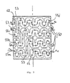
- This cooling action is achieved as a result of evaporation of the refrigerating fluid along a channel 50 (visible in detail in Figs. 3 and 4 ) formed on the outer surface of the cylindrical body 20; as can be seen, this channel 50 has a coil-like progression along superimposed horizontal circular bands 55a, 55b, 55c, 55d which are connected together by means of vertical sections 53.
- the jacket 40 is joined to the cylinder 20 so that the respective surfaces are juxtaposed and the channel 50 closed on the outside, thus defining a continuous path for the refrigerating fluid, at the ends of which an inlet 61 and an outlet 62 connected respectively to the pipes 22 and 24 are situated.
- the refrigerating fluid supplied by means of a compressor reaches the cylinder 20 in the liquid condition, passes into the pipe 22, enters the inlet 61 which is situated at the bottom of the body 20 (c.f. Fig. 3 ) and flows along the channel 50 along which it evaporates, cooling the jacket 40; when it reaches the outlet 62 it is in the gaseous state and is evacuated from the top via the return pipe 24.
- the methods with which the ice is formed are substantially similar to the known methods, in the sense that the water is sprayed onto the outer surface of the jacket 40 and freezes in contact with it when it is cooled from the inside by the refrigerating fluid which flows inside the channel 50; the ice is scraped off by the blades 91 of the knife 90 which rotates about the axis of the cylinder 20 as a result of operation by means of the gear wheel 89.
- the coil-like progression of the channel 50 which extends in the form of the various circular bands 55a, b, c, d causes a turbulent flow of the refrigerating fluid, thus favouring the heat exchange for cooling the jacket 40; in this connection it is important to note the considerable difference from the Italian Utility Model referred to further above in which the refrigerating fluid flows along straight sections oriented in the manner of the generatrices of the cooling cylinder so as to produce in fact a laminar movement without turbulence.
- a possible modification consists in forming the path for the refrigerating fluid by means of a raised rib on the wall of the body 20, instead of forming thereon the channel 50 as in the example shown in the drawings; it is obvious, however, that by mounting the jacket 40 externally, a fluid flow path equivalent to that already seen is obtained.
- the channel 50 (or aforementioned rib) may be formed on the jacket 40 instead of on the cylinder 20, which in this case will instead be smooth; in other words it is possible to reverse the position of the smooth or channelled surfaces which together form the coil-like flow path of the refrigerating fluid.
- This path may obviously be configured differently provided that it is able to promote the turbulence and therefore the heat exchange for cooling the jacket 40 of the cylinder 10; for example, instead of following the circular bands 55a, 55b, 55c, 55d which extend horizontally with respect to the cylindrical body 20, it could be possible to form a channel 50 with vertical sections, namely arranged along the generatrices of the body 20 as in the already mentioned Italian Utility Model, but with the coil-like progression explained above.
- This machine comprises a tubular body 120 on the outer surface of which a channel 150 identical to that formed on the cylindrical body 20 seen above is formed; a rotating screw (not shown in the drawing) is housed inside the body 120.
- a jacket or sleeve 140 is mounted on the outside of the tubular body 120 and closes off the channel 150 so as to define together therewith a path in which the refrigerating fluid supplied by an output pipe 122 and a return pipe 124 flows.
- the bottom part of the tubular body 120 is filled with water supplied by a pipe 125 and raised upwards by the screw, while at the same time the refrigerating fluid circulates inside the channel 150 and, evaporating, cools the wall of the tubular body 120.
- the ice is formed inside the cylinder, instead of outside, as in the example of Figs. 1-5 ; the operating principle and the advantages achieved by the channel are in any case the same.
Abstract
Description
- The invention relates to a cooling cylinder for forming ice flakes or granular ice according to the preamble of claim 1. Such a cooling cylinder is known for example from
US-A-2001/0 045 275 . - This type of ice, which is widely used to keep at a low temperature food inside containers for display or transportation, is obtained by means of apparatus which use a cooling cylinder such as, for example, that forming the subject of Italian Utility Model No.
0216265 - In short it may be stated that the cylinder of these apparatus consists of a central body in the form of a tubular interspace which is closed at the ends by two flanges; the interspace has, arranged inside it, radial baffles which define a channel extending along the generatrices of the cylinder. The refrigerating fluid is made to evaporate inside the channel and thus cools the outer surface of the cylinder onto which the water is sprayed: the latter freezes and is scraped off in the form of flakes by a knife rotating about the cylinder.
- The known apparatus described above is advantageous from a constructional point of view since the body of the cylinder may be manufactured by means of single casting of aluminium or the like: on the other hand, however, this constructional solution requires seals between the body of the cylinder and the flanges arranged at the ends in order to prevent leaks of the circulating fluid.
- Furthermore, the Applicant is of the opinion that it is advantageous to increase the heat exchange of the refrigerating fluid with the cooling cylinder since in this way it is possible to increase the hourly production of ice, all other conditions being equal, such as for example the fluid and water flowrate, the dimensions of the cylinder, etc.
- The technical problem which forms the basis of the present invention is therefore that of achieving these results: the idea for solving this problem consists in providing a novel cooling cylinder in which the path along which the refrigerating fluid flows has a winding progression with coil-like sections, which are preferably short compared to the height of the cylinder, such that the turbulence of the flow and consequently also the heat exchange increases.
- According to the invention this problem is solved by a cooling cylinder having the features of claim 1.
- Preferably the flow is obtained with a channel formed on the surface of the cylinder body, closed externally by a tubular jacket mounted on the aforementioned body.
- These and other characteristic features of the invention will be understood more clearly in the light of the description which is provided hereinbelow, relating to a preferred and non-exclusive example of embodiment, illustrated in the accompanying drawings in which:
-
Fig. 1 shows a cooling cylinder according to the invention; -
Fig. 2 shows a cross-section through the above cylinder, along the plane A-A ofFig. 1 ; -
Fig. 3 shows in detail the outer surface of the cooling cylinder according toFig. 1 ; -
Fig. 4 shows the planar extension of the surface according toFig. 3 ; -
Fig. 5 shows a horizontal cross-section through the apparatus according toFig. 1 along the plane B-B; -
Fig. 6 shows another application of the invention. - With reference to these figures, these show an overall view of a
cooling cylinder 10, according to the invention, which is intended to be used in combination with a compressor and a condenser, not shown in the drawings, in accordance with the usual operating principle of known refrigerating units. - The
cylinder 10 acts instead as an evaporator of the unit and comprises acentral body 20 with a cylindrical geometry, to which ajacket 40 is joined externally; in accordance with a preferred embodiment, thecylindrical body 20 is made of high-impact strength steel (instead of aluminium) and thejacket 40 is welded onto it at the ends so as not to require seals for sealing thereof. - Alternatively, the
cylindrical body 20 may be made of aluminium and thejacket 40 shrunk on it, while the seal between them is ensured by means of sealing gaskets. -
Respective flanges body 20, thus closing off the space inside them; these flanges are constrained together with isolatingspacers bolts 84 and the upper flange has aneck 86 through which twopipes - A collar 87 is mounted on the outside of the
neck 86 and is able to rotate on revolving bearings 88; agear wheel 89 is fixed (by means of screws visible inFig. 2 ) around the collar 87, while ascraper knife 90 projects radially therefrom; the knife has a series of comb-like blades 91 of the known type and is connected at the bottom by means of a radial tie-rod 92 to a rotatingring 93, so as to be free to rotate with respect to the vertical axis of the cylinder. - For this purpose, the apparatus in which the
cooling cylinder 10 is used has a motor-driven pinion (not shown in the drawings) which meshes with thegear wheel 89, causing rotation of theknife 90 so as to scrape off the ice. - The latter is formed as a result of freezing of the water which is sprayed onto the outside of the
jacket 40 by means of a pipe (not shown in the drawings) which rotates about thecylindrical body 20, integrally with theknife 91. - This cooling action is achieved as a result of evaporation of the refrigerating fluid along a channel 50 (visible in detail in
Figs. 3 and4 ) formed on the outer surface of thecylindrical body 20; as can be seen, thischannel 50 has a coil-like progression along superimposed horizontalcircular bands vertical sections 53. - The
jacket 40 is joined to thecylinder 20 so that the respective surfaces are juxtaposed and thechannel 50 closed on the outside, thus defining a continuous path for the refrigerating fluid, at the ends of which aninlet 61 and anoutlet 62 connected respectively to thepipes - Therefore, the refrigerating fluid supplied by means of a compressor (not shown in the drawings) reaches the
cylinder 20 in the liquid condition, passes into thepipe 22, enters theinlet 61 which is situated at the bottom of the body 20 (c.f.Fig. 3 ) and flows along thechannel 50 along which it evaporates, cooling thejacket 40; when it reaches theoutlet 62 it is in the gaseous state and is evacuated from the top via thereturn pipe 24. - From the explanation provided hitherto it is easy to understand the operating principle of the invention.
- In fact the methods with which the ice is formed are substantially similar to the known methods, in the sense that the water is sprayed onto the outer surface of the
jacket 40 and freezes in contact with it when it is cooled from the inside by the refrigerating fluid which flows inside thechannel 50; the ice is scraped off by theblades 91 of theknife 90 which rotates about the axis of thecylinder 20 as a result of operation by means of thegear wheel 89. - The coil-like progression of the
channel 50 which extends in the form of the variouscircular bands 55a, b, c, d causes a turbulent flow of the refrigerating fluid, thus favouring the heat exchange for cooling thejacket 40; in this connection it is important to note the considerable difference from the Italian Utility Model referred to further above in which the refrigerating fluid flows along straight sections oriented in the manner of the generatrices of the cooling cylinder so as to produce in fact a laminar movement without turbulence. - Consequently the efficiency of the
cylinder 10 according to the present invention is greater, all other conditions being equal, than that of the already mentioned known cylinder. - Variations of the invention with respect to that described hitherto are nevertheless possible.
- For example, a possible modification consists in forming the path for the refrigerating fluid by means of a raised rib on the wall of the
body 20, instead of forming thereon thechannel 50 as in the example shown in the drawings; it is obvious, however, that by mounting thejacket 40 externally, a fluid flow path equivalent to that already seen is obtained. - It moreover needs to be mentioned that the channel 50 (or aforementioned rib) may be formed on the
jacket 40 instead of on thecylinder 20, which in this case will instead be smooth; in other words it is possible to reverse the position of the smooth or channelled surfaces which together form the coil-like flow path of the refrigerating fluid. - This path may obviously be configured differently provided that it is able to promote the turbulence and therefore the heat exchange for cooling the
jacket 40 of thecylinder 10; for example, instead of following thecircular bands cylindrical body 20, it could be possible to form achannel 50 with vertical sections, namely arranged along the generatrices of thebody 20 as in the already mentioned Italian Utility Model, but with the coil-like progression explained above. - Finally it is possible that the principle of the invention may also be applied to apparatus of a type different that considered here.
- This possibility is illustrated in the last figure which shows (with a part removed) the
cooling cylinder 100 of a granular ice making machine; for the sake of simplicity, in this variant the elements common with the previous example have been indicated by the prefix "1". - This machine comprises a
tubular body 120 on the outer surface of which achannel 150 identical to that formed on thecylindrical body 20 seen above is formed; a rotating screw (not shown in the drawing) is housed inside thebody 120. - A jacket or sleeve 140 is mounted on the outside of the
tubular body 120 and closes off thechannel 150 so as to define together therewith a path in which the refrigerating fluid supplied by an output pipe 122 and areturn pipe 124 flows. - During operation of the apparatus, the bottom part of the
tubular body 120 is filled with water supplied by apipe 125 and raised upwards by the screw, while at the same time the refrigerating fluid circulates inside thechannel 150 and, evaporating, cools the wall of thetubular body 120. - As the water rises, it flows over the inner surface of the
body 120, freezing, and is then scraped off by the screw which conveys the ice towards the top end of thetubular body 120, from which it emerges in the form of flakes. - Basically, in this case the ice is formed inside the cylinder, instead of outside, as in the example of
Figs. 1-5 ; the operating principle and the advantages achieved by the channel are in any case the same. - It is therefore clear that the teaching of the invention is applicable with success to all ice-making machines where a wall is cooled by means of heat exchange with a refrigerating fluid which flows in contact with the said wall.
Claims (12)
- Cooling cylinder for forming granular ice, comprising a cylindrical body (20), a jacket (40) mounted on the outside thereof, a flow path (50) for refrigerating fluid defined between the outer surface of the cylindrical body (20) and the jacket (40), said flow path (50) being formed by superimposed horizontal circumferential bands (55a, 55b, 55c, 55d) which are connected together by means of vertical sections (53),
characterised in that each of said horizontal circumferential bands (55a, 55b, 55c, 55d) has a coil-like progression. - Cylinder according to Claim 1, in which said path (50) extends peripherally with respect to the cylindrical body (20).
- Cylinder according to Claims 1 and 2, in which said path (50) extends mainly in a circumferential direction with respect to the cylindrical body (20).
- Cylinder according to Claim 1, in which said path comprises a channel (50) formed on the outer surface of the cylindrical body (20) and the jacket (40) joined thereto.
- Cylinder according to Claim 1, in which said path comprises a channel (50) formed on the inner surface of the jacket (40) and the smooth outer surface of the cylindrical body (20).
- Cylinder according to Claims 4 and 5, in which the jacket (40) is welded to the cylindrical body (20) in a sealed manner.
- Ice-flake making apparatus, characterized in that it comprises a cooling cylinder (10) in accordance with Claim 1 to 6.
- Granular ice making apparatus comprising a cooling cylinder according to any claims 1 to 6 having a screw (125) arranged inside the cylindrical body of said cooling cylinder.
- Apparatus according to Claim 8, in which said path comprises a channel (150) formed on the outer surface of the tubular body (120) and the jacket (140) joined thereto.
- Apparatus according to Claim 8, in which said path comprises a channel (150) formed on the inner surface of the jacket (140) and the smooth outer surface of the tubular body (120).
- Apparatus according to Claims 8, 9 or 10, in which the part of the tubular body (120) where said path is defined consists of a drum assembled on the rest of the tubular body (120).
- Apparatus according to Claim 8, in which the drum is connected to the rest of the tubular body (120) by means of a joint with flanges or the like.
Priority Applications (1)
| Application Number | Priority Date | Filing Date | Title |
|---|---|---|---|
| PL05752779T PL1782004T3 (en) | 2004-07-16 | 2005-05-19 | Cooling cylinder for ice-flake making apparatus |
Applications Claiming Priority (2)
| Application Number | Priority Date | Filing Date | Title |
|---|---|---|---|
| IT001437A ITMI20041437A1 (en) | 2004-07-16 | 2004-07-16 | COOLING CYLINDER FOR ICE FORMING EQUIPMENT IN FLAKES |
| PCT/EP2005/052305 WO2006008203A1 (en) | 2004-07-16 | 2005-05-19 | Cooling cylinder for ice-flake making apparatus |
Publications (2)
| Publication Number | Publication Date |
|---|---|
| EP1782004A1 EP1782004A1 (en) | 2007-05-09 |
| EP1782004B1 true EP1782004B1 (en) | 2010-09-08 |
Family
ID=34970198
Family Applications (1)
| Application Number | Title | Priority Date | Filing Date |
|---|---|---|---|
| EP05752779A Active EP1782004B1 (en) | 2004-07-16 | 2005-05-19 | Cooling cylinder for ice-flake making apparatus |
Country Status (7)
| Country | Link |
|---|---|
| EP (1) | EP1782004B1 (en) |
| AT (1) | ATE480743T1 (en) |
| DE (1) | DE602005023486D1 (en) |
| ES (1) | ES2349796T3 (en) |
| IT (1) | ITMI20041437A1 (en) |
| PL (1) | PL1782004T3 (en) |
| WO (1) | WO2006008203A1 (en) |
Families Citing this family (2)
| Publication number | Priority date | Publication date | Assignee | Title |
|---|---|---|---|---|
| KR101742312B1 (en) | 2016-01-05 | 2017-05-31 | 송화종 | Cooling Drum for ice machine |
| KR101939048B1 (en) * | 2017-01-10 | 2019-01-17 | 주식회사 대일 | Double Tube Type Sea Water Sherbet Ice Generator |
Family Cites Families (5)
| Publication number | Priority date | Publication date | Assignee | Title |
|---|---|---|---|---|
| AU627651B2 (en) * | 1990-07-13 | 1992-08-27 | Alden Commercial Refrigeration Pty. Ltd. | Ice making apparatus |
| US5799726A (en) * | 1996-01-23 | 1998-09-01 | Frank; Jimmy I. | Refrigerated mixing chamber and method for making same |
| US6253573B1 (en) * | 1999-03-10 | 2001-07-03 | Specialty Equipment Companies, Inc. | High efficiency refrigeration system |
| US6343416B1 (en) * | 1999-07-07 | 2002-02-05 | Hoshizaki America, Inc. | Method of preparing surfaces of a heat exchanger |
| US20010045275A1 (en) * | 2000-05-25 | 2001-11-29 | Hoshizaki Denki Kabushiki Kaisha | Cylindrical heat exchanger |
-
2004
- 2004-07-16 IT IT001437A patent/ITMI20041437A1/en unknown
-
2005
- 2005-05-19 DE DE602005023486T patent/DE602005023486D1/en active Active
- 2005-05-19 AT AT05752779T patent/ATE480743T1/en not_active IP Right Cessation
- 2005-05-19 EP EP05752779A patent/EP1782004B1/en active Active
- 2005-05-19 ES ES05752779T patent/ES2349796T3/en active Active
- 2005-05-19 WO PCT/EP2005/052305 patent/WO2006008203A1/en active Application Filing
- 2005-05-19 PL PL05752779T patent/PL1782004T3/en unknown
Also Published As
| Publication number | Publication date |
|---|---|
| ITMI20041437A1 (en) | 2004-10-16 |
| ES2349796T3 (en) | 2011-01-11 |
| WO2006008203A1 (en) | 2006-01-26 |
| DE602005023486D1 (en) | 2010-10-21 |
| ATE480743T1 (en) | 2010-09-15 |
| EP1782004A1 (en) | 2007-05-09 |
| PL1782004T3 (en) | 2011-03-31 |
Similar Documents
| Publication | Publication Date | Title |
|---|---|---|
| US8132424B2 (en) | Ice machines with extruded heat exchanger | |
| US9714783B2 (en) | Extruded ice making machine with extrusion die secured without screws | |
| EP1782004B1 (en) | Cooling cylinder for ice-flake making apparatus | |
| CN101744084A (en) | Ice cream mixing drum | |
| KR100296653B1 (en) | Heat exchanger for ice making apparatus in cooling system | |
| CN210584952U (en) | Steaming reaction device for producing all-round alkali-resistant closed primer | |
| US2354752A (en) | Strainer | |
| US5735136A (en) | Flake freezing machine and system using same | |
| JP2927439B2 (en) | Ice making equipment | |
| US3277667A (en) | Freezing | |
| US20130192290A1 (en) | Device for the Production of Flake Ice | |
| KR20120126488A (en) | Piece ice manufacturing implement | |
| US2307311A (en) | Refrigerating machine | |
| CN104075515A (en) | Multi-sectional modularized scrapping blade combined type fluidized ice crystal machine | |
| US2237107A (en) | Liquid cooler | |
| CN219879109U (en) | Thin film evaporator with built-in condenser | |
| US2102866A (en) | Chilling device | |
| WO2019139015A1 (en) | Double-piped ice-making machine | |
| CN215412618U (en) | Evaporator for ice maker | |
| CN220242055U (en) | Reclaimed rubber refiner | |
| JP2009168407A (en) | Drum type ice making machine | |
| CN103851848A (en) | Suspension scraping plate type ice slurry ice crystallizer | |
| RU2221202C1 (en) | Crystallizer for continuous freezing-out and flake ice producing | |
| RU2094074C1 (en) | Roll crystallizer | |
| CN108120092A (en) | Shell is connected double space plate cold-water heat exchanger |
Legal Events
| Date | Code | Title | Description |
|---|---|---|---|
| PUAI | Public reference made under article 153(3) epc to a published international application that has entered the european phase |
Free format text: ORIGINAL CODE: 0009012 |
|
| 17P | Request for examination filed |
Effective date: 20070111 |
|
| AK | Designated contracting states |
Kind code of ref document: A1 Designated state(s): AT BE BG CH CY CZ DE DK EE ES FI FR GB GR HU IE IS IT LI LT LU MC NL PL PT RO SE SI SK TR |
|
| AX | Request for extension of the european patent |
Extension state: AL |
|
| RAX | Requested extension states of the european patent have changed |
Extension state: AL Payment date: 20070111 |
|
| 17Q | First examination report despatched |
Effective date: 20100311 |
|
| GRAP | Despatch of communication of intention to grant a patent |
Free format text: ORIGINAL CODE: EPIDOSNIGR1 |
|
| GRAS | Grant fee paid |
Free format text: ORIGINAL CODE: EPIDOSNIGR3 |
|
| GRAA | (expected) grant |
Free format text: ORIGINAL CODE: 0009210 |
|
| AK | Designated contracting states |
Kind code of ref document: B1 Designated state(s): AT BE BG CH CY CZ DE DK EE ES FI FR GB GR HU IE IS IT LI LT LU MC NL PL PT RO SE SI SK TR |
|
| AX | Request for extension of the european patent |
Extension state: AL |
|
| REG | Reference to a national code |
Ref country code: GB Ref legal event code: FG4D |
|
| REG | Reference to a national code |
Ref country code: CH Ref legal event code: EP |
|
| REG | Reference to a national code |
Ref country code: IE Ref legal event code: FG4D |
|
| REF | Corresponds to: |
Ref document number: 602005023486 Country of ref document: DE Date of ref document: 20101021 Kind code of ref document: P |
|
| REG | Reference to a national code |
Ref country code: RO Ref legal event code: EPE |
|
| REG | Reference to a national code |
Ref country code: GR Ref legal event code: EP Ref document number: 20100402645 Country of ref document: GR |
|
| REG | Reference to a national code |
Ref country code: NL Ref legal event code: VDEP Effective date: 20100908 |
|
| REG | Reference to a national code |
Ref country code: ES Ref legal event code: FG2A Effective date: 20101228 |
|
| PG25 | Lapsed in a contracting state [announced via postgrant information from national office to epo] |
Ref country code: LT Free format text: LAPSE BECAUSE OF FAILURE TO SUBMIT A TRANSLATION OF THE DESCRIPTION OR TO PAY THE FEE WITHIN THE PRESCRIBED TIME-LIMIT Effective date: 20100908 Ref country code: FI Free format text: LAPSE BECAUSE OF FAILURE TO SUBMIT A TRANSLATION OF THE DESCRIPTION OR TO PAY THE FEE WITHIN THE PRESCRIBED TIME-LIMIT Effective date: 20100908 Ref country code: AT Free format text: LAPSE BECAUSE OF FAILURE TO SUBMIT A TRANSLATION OF THE DESCRIPTION OR TO PAY THE FEE WITHIN THE PRESCRIBED TIME-LIMIT Effective date: 20100908 |
|
| LTIE | Lt: invalidation of european patent or patent extension |
Effective date: 20100908 |
|
| PG25 | Lapsed in a contracting state [announced via postgrant information from national office to epo] |
Ref country code: SI Free format text: LAPSE BECAUSE OF FAILURE TO SUBMIT A TRANSLATION OF THE DESCRIPTION OR TO PAY THE FEE WITHIN THE PRESCRIBED TIME-LIMIT Effective date: 20100908 Ref country code: CY Free format text: LAPSE BECAUSE OF FAILURE TO SUBMIT A TRANSLATION OF THE DESCRIPTION OR TO PAY THE FEE WITHIN THE PRESCRIBED TIME-LIMIT Effective date: 20100908 |
|
| REG | Reference to a national code |
Ref country code: SK Ref legal event code: T3 Ref document number: E 8294 Country of ref document: SK |
|
| PG25 | Lapsed in a contracting state [announced via postgrant information from national office to epo] |
Ref country code: NL Free format text: LAPSE BECAUSE OF FAILURE TO SUBMIT A TRANSLATION OF THE DESCRIPTION OR TO PAY THE FEE WITHIN THE PRESCRIBED TIME-LIMIT Effective date: 20100908 Ref country code: SE Free format text: LAPSE BECAUSE OF FAILURE TO SUBMIT A TRANSLATION OF THE DESCRIPTION OR TO PAY THE FEE WITHIN THE PRESCRIBED TIME-LIMIT Effective date: 20100908 |
|
| REG | Reference to a national code |
Ref country code: PL Ref legal event code: T3 |
|
| PG25 | Lapsed in a contracting state [announced via postgrant information from national office to epo] |
Ref country code: EE Free format text: LAPSE BECAUSE OF FAILURE TO SUBMIT A TRANSLATION OF THE DESCRIPTION OR TO PAY THE FEE WITHIN THE PRESCRIBED TIME-LIMIT Effective date: 20100908 Ref country code: PT Free format text: LAPSE BECAUSE OF FAILURE TO SUBMIT A TRANSLATION OF THE DESCRIPTION OR TO PAY THE FEE WITHIN THE PRESCRIBED TIME-LIMIT Effective date: 20110110 Ref country code: IS Free format text: LAPSE BECAUSE OF FAILURE TO SUBMIT A TRANSLATION OF THE DESCRIPTION OR TO PAY THE FEE WITHIN THE PRESCRIBED TIME-LIMIT Effective date: 20110108 |
|
| PG25 | Lapsed in a contracting state [announced via postgrant information from national office to epo] |
Ref country code: BE Free format text: LAPSE BECAUSE OF FAILURE TO SUBMIT A TRANSLATION OF THE DESCRIPTION OR TO PAY THE FEE WITHIN THE PRESCRIBED TIME-LIMIT Effective date: 20100908 |
|
| PLBE | No opposition filed within time limit |
Free format text: ORIGINAL CODE: 0009261 |
|
| STAA | Information on the status of an ep patent application or granted ep patent |
Free format text: STATUS: NO OPPOSITION FILED WITHIN TIME LIMIT |
|
| 26N | No opposition filed |
Effective date: 20110609 |
|
| PG25 | Lapsed in a contracting state [announced via postgrant information from national office to epo] |
Ref country code: DK Free format text: LAPSE BECAUSE OF FAILURE TO SUBMIT A TRANSLATION OF THE DESCRIPTION OR TO PAY THE FEE WITHIN THE PRESCRIBED TIME-LIMIT Effective date: 20100908 |
|
| REG | Reference to a national code |
Ref country code: DE Ref legal event code: R097 Ref document number: 602005023486 Country of ref document: DE Effective date: 20110609 |
|
| PG25 | Lapsed in a contracting state [announced via postgrant information from national office to epo] |
Ref country code: MC Free format text: LAPSE BECAUSE OF NON-PAYMENT OF DUE FEES Effective date: 20110531 |
|
| REG | Reference to a national code |
Ref country code: CH Ref legal event code: PL |
|
| GBPC | Gb: european patent ceased through non-payment of renewal fee |
Effective date: 20110519 |
|
| PG25 | Lapsed in a contracting state [announced via postgrant information from national office to epo] |
Ref country code: LI Free format text: LAPSE BECAUSE OF NON-PAYMENT OF DUE FEES Effective date: 20110531 Ref country code: CH Free format text: LAPSE BECAUSE OF NON-PAYMENT OF DUE FEES Effective date: 20110531 |
|
| REG | Reference to a national code |
Ref country code: IE Ref legal event code: MM4A |
|
| REG | Reference to a national code |
Ref country code: DE Ref legal event code: R119 Ref document number: 602005023486 Country of ref document: DE Effective date: 20111201 |
|
| PG25 | Lapsed in a contracting state [announced via postgrant information from national office to epo] |
Ref country code: IE Free format text: LAPSE BECAUSE OF NON-PAYMENT OF DUE FEES Effective date: 20110519 |
|
| PG25 | Lapsed in a contracting state [announced via postgrant information from national office to epo] |
Ref country code: GB Free format text: LAPSE BECAUSE OF NON-PAYMENT OF DUE FEES Effective date: 20110519 |
|
| PG25 | Lapsed in a contracting state [announced via postgrant information from national office to epo] |
Ref country code: LU Free format text: LAPSE BECAUSE OF NON-PAYMENT OF DUE FEES Effective date: 20110519 |
|
| PG25 | Lapsed in a contracting state [announced via postgrant information from national office to epo] |
Ref country code: DE Free format text: LAPSE BECAUSE OF NON-PAYMENT OF DUE FEES Effective date: 20111201 |
|
| PG25 | Lapsed in a contracting state [announced via postgrant information from national office to epo] |
Ref country code: BG Free format text: LAPSE BECAUSE OF FAILURE TO SUBMIT A TRANSLATION OF THE DESCRIPTION OR TO PAY THE FEE WITHIN THE PRESCRIBED TIME-LIMIT Effective date: 20101208 |
|
| PG25 | Lapsed in a contracting state [announced via postgrant information from national office to epo] |
Ref country code: HU Free format text: LAPSE BECAUSE OF FAILURE TO SUBMIT A TRANSLATION OF THE DESCRIPTION OR TO PAY THE FEE WITHIN THE PRESCRIBED TIME-LIMIT Effective date: 20100908 |
|
| REG | Reference to a national code |
Ref country code: FR Ref legal event code: PLFP Year of fee payment: 12 |
|
| REG | Reference to a national code |
Ref country code: FR Ref legal event code: PLFP Year of fee payment: 13 |
|
| REG | Reference to a national code |
Ref country code: FR Ref legal event code: PLFP Year of fee payment: 14 |
|
| PGFP | Annual fee paid to national office [announced via postgrant information from national office to epo] |
Ref country code: RO Payment date: 20200626 Year of fee payment: 16 Ref country code: CZ Payment date: 20200624 Year of fee payment: 16 Ref country code: GR Payment date: 20200624 Year of fee payment: 16 |
|
| PGFP | Annual fee paid to national office [announced via postgrant information from national office to epo] |
Ref country code: SK Payment date: 20200625 Year of fee payment: 16 |
|
| REG | Reference to a national code |
Ref country code: SK Ref legal event code: MM4A Ref document number: E 8294 Country of ref document: SK Effective date: 20210519 |
|
| PG25 | Lapsed in a contracting state [announced via postgrant information from national office to epo] |
Ref country code: CZ Free format text: LAPSE BECAUSE OF NON-PAYMENT OF DUE FEES Effective date: 20210519 Ref country code: SK Free format text: LAPSE BECAUSE OF NON-PAYMENT OF DUE FEES Effective date: 20210519 Ref country code: RO Free format text: LAPSE BECAUSE OF NON-PAYMENT OF DUE FEES Effective date: 20210519 |
|
| PG25 | Lapsed in a contracting state [announced via postgrant information from national office to epo] |
Ref country code: GR Free format text: LAPSE BECAUSE OF NON-PAYMENT OF DUE FEES Effective date: 20211207 |
|
| PGFP | Annual fee paid to national office [announced via postgrant information from national office to epo] |
Ref country code: IT Payment date: 20230126 Year of fee payment: 19 |
|
| PGFP | Annual fee paid to national office [announced via postgrant information from national office to epo] |
Ref country code: FR Payment date: 20230517 Year of fee payment: 19 Ref country code: ES Payment date: 20230621 Year of fee payment: 19 |
|
| PGFP | Annual fee paid to national office [announced via postgrant information from national office to epo] |
Ref country code: TR Payment date: 20230515 Year of fee payment: 19 Ref country code: PL Payment date: 20230508 Year of fee payment: 19 |