EP1782002B1 - Oil separator for vapor compression system compressor - Google Patents
Oil separator for vapor compression system compressor Download PDFInfo
- Publication number
- EP1782002B1 EP1782002B1 EP05763149.1A EP05763149A EP1782002B1 EP 1782002 B1 EP1782002 B1 EP 1782002B1 EP 05763149 A EP05763149 A EP 05763149A EP 1782002 B1 EP1782002 B1 EP 1782002B1
- Authority
- EP
- European Patent Office
- Prior art keywords
- refrigerant
- oil
- oil separator
- motor
- compressor
- Prior art date
- Legal status (The legal status is an assumption and is not a legal conclusion. Google has not performed a legal analysis and makes no representation as to the accuracy of the status listed.)
- Not-in-force
Links
Images

Classifications
-
- F—MECHANICAL ENGINEERING; LIGHTING; HEATING; WEAPONS; BLASTING
- F25—REFRIGERATION OR COOLING; COMBINED HEATING AND REFRIGERATION SYSTEMS; HEAT PUMP SYSTEMS; MANUFACTURE OR STORAGE OF ICE; LIQUEFACTION SOLIDIFICATION OF GASES
- F25B—REFRIGERATION MACHINES, PLANTS OR SYSTEMS; COMBINED HEATING AND REFRIGERATION SYSTEMS; HEAT PUMP SYSTEMS
- F25B9/00—Compression machines, plants or systems, in which the refrigerant is air or other gas of low boiling point
- F25B9/002—Compression machines, plants or systems, in which the refrigerant is air or other gas of low boiling point characterised by the refrigerant
- F25B9/008—Compression machines, plants or systems, in which the refrigerant is air or other gas of low boiling point characterised by the refrigerant the refrigerant being carbon dioxide
-
- F—MECHANICAL ENGINEERING; LIGHTING; HEATING; WEAPONS; BLASTING
- F04—POSITIVE - DISPLACEMENT MACHINES FOR LIQUIDS; PUMPS FOR LIQUIDS OR ELASTIC FLUIDS
- F04B—POSITIVE-DISPLACEMENT MACHINES FOR LIQUIDS; PUMPS
- F04B39/00—Component parts, details, or accessories, of pumps or pumping systems specially adapted for elastic fluids, not otherwise provided for in, or of interest apart from, groups F04B25/00 - F04B37/00
- F04B39/06—Cooling; Heating; Prevention of freezing
- F04B39/066—Cooling by ventilation
-
- F—MECHANICAL ENGINEERING; LIGHTING; HEATING; WEAPONS; BLASTING
- F04—POSITIVE - DISPLACEMENT MACHINES FOR LIQUIDS; PUMPS FOR LIQUIDS OR ELASTIC FLUIDS
- F04B—POSITIVE-DISPLACEMENT MACHINES FOR LIQUIDS; PUMPS
- F04B39/00—Component parts, details, or accessories, of pumps or pumping systems specially adapted for elastic fluids, not otherwise provided for in, or of interest apart from, groups F04B25/00 - F04B37/00
- F04B39/16—Filtration; Moisture separation
-
- F—MECHANICAL ENGINEERING; LIGHTING; HEATING; WEAPONS; BLASTING
- F25—REFRIGERATION OR COOLING; COMBINED HEATING AND REFRIGERATION SYSTEMS; HEAT PUMP SYSTEMS; MANUFACTURE OR STORAGE OF ICE; LIQUEFACTION SOLIDIFICATION OF GASES
- F25B—REFRIGERATION MACHINES, PLANTS OR SYSTEMS; COMBINED HEATING AND REFRIGERATION SYSTEMS; HEAT PUMP SYSTEMS
- F25B43/00—Arrangements for separating or purifying gases or liquids; Arrangements for vaporising the residuum of liquid refrigerant, e.g. by heat
- F25B43/02—Arrangements for separating or purifying gases or liquids; Arrangements for vaporising the residuum of liquid refrigerant, e.g. by heat for separating lubricants from the refrigerant
-
- F—MECHANICAL ENGINEERING; LIGHTING; HEATING; WEAPONS; BLASTING
- F25—REFRIGERATION OR COOLING; COMBINED HEATING AND REFRIGERATION SYSTEMS; HEAT PUMP SYSTEMS; MANUFACTURE OR STORAGE OF ICE; LIQUEFACTION SOLIDIFICATION OF GASES
- F25B—REFRIGERATION MACHINES, PLANTS OR SYSTEMS; COMBINED HEATING AND REFRIGERATION SYSTEMS; HEAT PUMP SYSTEMS
- F25B2309/00—Gas cycle refrigeration machines
- F25B2309/06—Compression machines, plants or systems characterised by the refrigerant being carbon dioxide
- F25B2309/061—Compression machines, plants or systems characterised by the refrigerant being carbon dioxide with cycle highest pressure above the supercritical pressure
-
- F—MECHANICAL ENGINEERING; LIGHTING; HEATING; WEAPONS; BLASTING
- F25—REFRIGERATION OR COOLING; COMBINED HEATING AND REFRIGERATION SYSTEMS; HEAT PUMP SYSTEMS; MANUFACTURE OR STORAGE OF ICE; LIQUEFACTION SOLIDIFICATION OF GASES
- F25B—REFRIGERATION MACHINES, PLANTS OR SYSTEMS; COMBINED HEATING AND REFRIGERATION SYSTEMS; HEAT PUMP SYSTEMS
- F25B31/00—Compressor arrangements
- F25B31/006—Cooling of compressor or motor
Definitions
- This invention relates to a compressor for a vapor compression system including an oil separator.
- Compressors employ a motor for driving a pump mechanism to compress fluid and, therefore, typically contain lubricant for reducing friction between sliding surfaces.
- an electric motor drives the pump mechanism through a driveline assembly.
- Refrigerant from the vapor compression system may flow over and around the motor and portions of the driveline.
- Lubricant typically flows through and around portions of the driveline to lubricate the sliding surfaces.
- Lubricant mixed in with the refrigerant can reduce efficiency and reliability of the vapor compression system.
- Lubricant carried along with the refrigerant flow can inhibit heat transfer and reduce the effectiveness of heat exchangers.
- lubricant carried with the refrigerant can plug small holes and inhibit performance of system components such as expanders.
- lubricant carried with the refrigerant can accumulate in unwanted or unexpected places within the compression system and may result in a loss of lubricant available for reducing friction and wear inside the compressor, thus reducing reliability.
- a transcritical vapor compression system includes a refrigerant exiting the compressor in a supercritical state.
- Refrigerant enters the compressor in a low-pressure state and commonly flows over the electric motor to aid in cooling the motor and reducing its operating temperature.
- Oil from the driveline can mix with the refrigerant and enter a compression chamber with the refrigerant.
- an oil-separating device to separate the oil from the refrigerant.
- an oil-separating device is employed after the compression chamber in the high-pressure portion of the system. In a transcritical system, this in the supercritical state.
- Oil separators typically include a passage for draining oil back to an oil sump on the low-pressure, sub-critical portion of the vapor compression system. This passage creates a constant leak within the vapor compression system that can reduce system efficiency.
- Oil separators disposed after the compression chamber must include relatively thicker walls, and high-pressure seals to accommodated the greater pressures. Further, refrigerants in a super-critical state, particularly carbon dioxide, tend to be extremely soluble. This causes oil to be saturated within the supercritical refrigerant. Oil saturated within the super critical refrigerant is very difficult to remove efficiently. The difficulties caused by the use of an oil separator on the supercritical side of a vapor compression system limit some systems to run entirely below a critical point. This can limit the type of refrigerant utilized in the system.
- This invention is a compressor including a low-pressure oil separator for a transcritical vapor compression system that separates oil from refrigerant after the refrigerant passes over a drive motor and before entering a compression chamber.
- the compressor assembly includes a motor, a drive assembly, an oil separator, a compressor chamber and an oil sump. Refrigerant flows over and around the drive motor to reduce its operating temperature.
- the drive assembly includes moving parts that are lubricated by oil. Oil within the drive assembly in some instances mixes with the refrigerant.
- the oil separator is disposed after the compressor motor but before the compression chamber. In this position oil is removed from the refrigerant prior to compression above the critical point. The oil separator removes substantially all of the oil that may become mixed with refrigerant prior to the refrigerant entering the compression chamber. Oil removed with an oil separator is transferred to an oil sump that is also on the low-pressure or sub-critical portion of the transcritical vapor compression system.
- the compressor of this invention includes a low-pressure side oil separator for removing oil from refrigerant before the refrigerant enters the compression chamber.
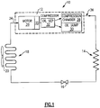
- a transcritical vapor compression system 10 includes a compressor 12, a heat exchanger 14, an expansion valve 16, and an evaporator 18.
- a fan 20 is provided for blowing air across the evaporator 18.
- the vapor compression system 10 preferably uses carbon dioxide as the refrigerant. However, other refrigerants that are known to workers skilled in the art are also within the contemplation of this invention.
- Refrigerant within the vapor compression system 10 exits the compression chamber 28 of the compressor 12 at a temperature and pressure above a critical point.
- the refrigerant flows through the heat exchanger 14. Heat from the refrigerant is rejected to another fluid medium for use in heating water or air.
- the high-pressure, high temperature refrigerant then moves from the heat exchanger 14 to an expansion valve 16.
- the expansion valve 16 regulates flow of refrigerant between high and low pressures.
- Refrigerant exiting the expansion valve 16 flows to the evaporator 18.
- the refrigerant accepts heat from the outside air.
- the fan 20 blows air across the evaporator 18 to improve the efficiency of this process.
- Refrigerant leaving the evaporator 18 enters the compressor 12 at an inlet 34.
- Refrigerant flows around and over a motor 26. Refrigerant flowing around the motor absorbs a portion of heat generated by the motor 26 to reduce its operating temperature.
- a driveline assembly 25 connected to the motor 26 inside compressor 12 require lubrication and are therefore provided with a lubricant such as oil.
- This lubricant is preferably maintained within the driveline assembly 25 attached to motor 26 such that no oil is emitted into the refrigerant flow. However, in some instances some oil becomes intermixed with the refrigerant used to cool the motor 26.
- the compressor 12 of this invention includes an oil separator 32 that is disposed between the motor 26 and the compression chamber 28. Refrigerant flowing over the motor 26 flows into an oil separator 32. The oil is then substantially removed from the refrigerant and directed towards an oil sump 30 for reuse to lubricate the moving parts of the drive assembly 25 attached to the motor 26 inside the compressor 12. The substantially oil free refrigerant exits the oil separator 32 and enters the compression chamber 28.
- the oil separator 32 can comprise coalescing medium, serpentine passages, centrifugal separators or other devices.
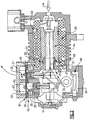
- a cross-sectional view of a compressor 12 according to an embodiment of this invention is shown and includes an inlet 34 for entering sub-critical refrigerant and an outlet 36 for exiting supercritical refrigerant.
- Refrigerant flows through a flow path 50 disposed adjacent the motor 26.
- the flow path 50 directs refrigerant flow around the motor 26 to absorb heat radiating from the motor 26.
- the flow path 50 directs refrigerant flow from the inlet 34 over the motor 26 and to a suction plenum 42.
- the flow path 50 is annular about the motor 26.
- the motor 26 includes a rotor 44 supported on at least one bearing 46.
- the bearing 46 includes a lubricant to limit or eliminate friction between sliding surfaces.
- the oil 48 in some instances can exit bearing 46 creating an oil-containing portion 51 within the flow path 50.
- the oil-containing portion 51 is disposed substantially adjacent bearing 46. Oil within the refrigerant flow, if allowed to remain within the refrigerant flow would enter the compression chamber 28 of the compressor 12 and flow with the refrigerant to the high-pressure portion of this system.
- a valve plate 38 is mounted to a crankcase 39 and a head cover 37 is attached to the valve plate 38. Gaskets 40 seal the interface between the crankcase 39, valve plate 38 and head cover 37.
- the oil separator 32 is disposed within the suction plenum 42.
- the suction plenum 42 is in communication with a plurality of passages 43 defined within the valve plate 38. The passages within the valve plate 38 communicate refrigerant from the flow path 50 to the suction plenum 42.
- a coalescing material 45 is disposed within the suction plenum 42.
- the coalescing material 45 is preferably a highly porous material that allows refrigerant flow while capturing oil droplets.
- the coalescing material may be a porous metal or synthetic material.
- Refrigerant containing oil 48 flows through the suction plenum 42 to the compression chambers 28. Oil within the refrigerant is separated and accumulated within the coalescing material 45.
- the coalescing material 45 collects and gathers the oil and drains it to a sump.
- An oil outlet 41 is provided to communicate oil from the suction plenum 42 to the oil sump.
- the suction plenum 42 includes the coalescing medium 45.
- the suction plenum 42 is shown where the refrigerant is collected before entering the compression chambers 28 through the passages 43. Refrigerant enters the suction plenum 42 through inlet 47.
- the suction plenum 42 is filled with coalescing medium 45. Refrigerant permeates through the coalescing medium 45 while the oil is collected on the surface of the coalescing material 45. Oil drains off through the outlet 41 to the oil sump 30.
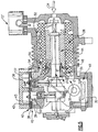
- FIG. 5 is a cross-sectional view of a compressor 12' according to another embodiment of this invention.
- the compressor 12' includes a passage 54 that directs refrigerant flowing around the motor 26 to the suction plenum 42.
- the passage 54 extends into the refrigerant, flow path 50 a distance from the oil containing portion 51 , and includes an inlet 56 spaced apart from the oil-containing portion 51 of the flow path 50. Because the inlet 56 of the passage 54 is spaced apart from the oil-containing portion 51 of the refrigerant flow path 50, refrigerant entering the inlet 56 does not contain oil that may have been emitted from bearing assemblies 46.
- Passage 54 isolates refrigerant of the oil-containing portion 51 from refrigerant within the flow path 50. Isolation of the oil-containing portion 51 of the refrigerant substantially prevents oil 48 from becoming intermixed with refrigerant flowing into the compression chambers 28.
- refrigerant enters the inlet 34 at a sub-critical point and flows around the motor 26.
- the refrigerant flows around the motor 26 in an annular flow path 50.
- Refrigerant within the annular flow path 50 absorbs heat from the motor 26 to reduce its operating temperature.
- the inlet 56 of the passage 54 is spaced apart from the bearing 46 to direct refrigerant into the suction plenum 42 before becoming intermixed with oil in the oil-containing portion 51.
- the inlet 56 is spaced apart from the bearing 46 such that substantially no oil is drawn into the compression chamber 28.
Description
- This invention relates to a compressor for a vapor compression system including an oil separator.
- Compressors employ a motor for driving a pump mechanism to compress fluid and, therefore, typically contain lubricant for reducing friction between sliding surfaces. In hermetic or semi-hermetic compressors, an electric motor drives the pump mechanism through a driveline assembly. Refrigerant from the vapor compression system may flow over and around the motor and portions of the driveline. Lubricant typically flows through and around portions of the driveline to lubricate the sliding surfaces.
- Although the primary lubricant flow path is mostly separate from the refrigerant flow path, some lubricant still can become mixed with the refrigerant. Lubricant mixed in with the refrigerant can reduce efficiency and reliability of the vapor compression system. Lubricant carried along with the refrigerant flow can inhibit heat transfer and reduce the effectiveness of heat exchangers. Further, lubricant carried with the refrigerant can plug small holes and inhibit performance of system components such as expanders. In addition, lubricant carried with the refrigerant can accumulate in unwanted or unexpected places within the compression system and may result in a loss of lubricant available for reducing friction and wear inside the compressor, thus reducing reliability.
- A transcritical vapor compression system includes a refrigerant exiting the compressor in a supercritical state. Refrigerant enters the compressor in a low-pressure state and commonly flows over the electric motor to aid in cooling the motor and reducing its operating temperature. Oil from the driveline can mix with the refrigerant and enter a compression chamber with the refrigerant. It is common to employ an oil-separating device to separate the oil from the refrigerant. Typically, an oil-separating device is employed after the compression chamber in the high-pressure portion of the system. In a transcritical system, this in the supercritical state. Oil separators typically include a passage for draining oil back to an oil sump on the low-pressure, sub-critical portion of the vapor compression system. This passage creates a constant leak within the vapor compression system that can reduce system efficiency.
- Oil separators disposed after the compression chamber must include relatively thicker walls, and high-pressure seals to accommodated the greater pressures. Further, refrigerants in a super-critical state, particularly carbon dioxide, tend to be extremely soluble. This causes oil to be saturated within the supercritical refrigerant. Oil saturated within the super critical refrigerant is very difficult to remove efficiently. The difficulties caused by the use of an oil separator on the supercritical side of a vapor compression system limit some systems to run entirely below a critical point. This can limit the type of refrigerant utilized in the system.
- Accordingly, it is desirable to develop a low-pressure side oil separator for separating oil from refrigerant.
- A prior art vapor compression system, having the features of the preamble of claim 1, is shown in
US 4,592,703 .JP-10103246 - According to the present invention, there is provided a vapor compression system as claimed in claim 1.
- This invention is a compressor including a low-pressure oil separator for a transcritical vapor compression system that separates oil from refrigerant after the refrigerant passes over a drive motor and before entering a compression chamber.
- A transcritical vapor compression system utilizing carbon dioxide as the refrigerant cycles between a high pressure above a critical point and a low pressure below the critical point. The compressor assembly includes a motor, a drive assembly, an oil separator, a compressor chamber and an oil sump. Refrigerant flows over and around the drive motor to reduce its operating temperature. The drive assembly includes moving parts that are lubricated by oil. Oil within the drive assembly in some instances mixes with the refrigerant.
- The oil separator is disposed after the compressor motor but before the compression chamber. In this position oil is removed from the refrigerant prior to compression above the critical point. The oil separator removes substantially all of the oil that may become mixed with refrigerant prior to the refrigerant entering the compression chamber. Oil removed with an oil separator is transferred to an oil sump that is also on the low-pressure or sub-critical portion of the transcritical vapor compression system.
- Accordingly, the compressor of this invention includes a low-pressure side oil separator for removing oil from refrigerant before the refrigerant enters the compression chamber.
- The various features and advantages of this invention will become apparent to those skilled in the art from the following detailed description of the currently preferred embodiment. The drawings that accompany the detailed description can be briefly described as follows:
-
Figure 1 is a schematic view of a transcritical vapor compression system according to this invention; -
Figure 2 is a cross-sectional view of a compressor including an oil separator according to this invention; -
Figure 3 is an enlarged cross sectional view of the compressor according to this invention; -
Figure 4 is a top view of a suction plenum including an oil coalescing medium; and -
Figure 5 is a cross-sectional view of a compressor including an oil isolation passage according to this invention. - Referring to
Figure 1 , a transcriticalvapor compression system 10 includes acompressor 12, aheat exchanger 14, anexpansion valve 16, and anevaporator 18. Afan 20 is provided for blowing air across theevaporator 18. Thevapor compression system 10 preferably uses carbon dioxide as the refrigerant. However, other refrigerants that are known to workers skilled in the art are also within the contemplation of this invention. - Refrigerant within the
vapor compression system 10 exits thecompression chamber 28 of thecompressor 12 at a temperature and pressure above a critical point. The refrigerant flows through theheat exchanger 14. Heat from the refrigerant is rejected to another fluid medium for use in heating water or air. The high-pressure, high temperature refrigerant then moves from theheat exchanger 14 to anexpansion valve 16. Theexpansion valve 16 regulates flow of refrigerant between high and low pressures. - Refrigerant exiting the
expansion valve 16 flows to theevaporator 18. In theevaporator 18 the refrigerant accepts heat from the outside air. Thefan 20 blows air across theevaporator 18 to improve the efficiency of this process. Refrigerant leaving theevaporator 18 enters thecompressor 12 at aninlet 34. Refrigerant flows around and over amotor 26. Refrigerant flowing around the motor absorbs a portion of heat generated by themotor 26 to reduce its operating temperature. - The moving parts of a
driveline assembly 25 connected to themotor 26 insidecompressor 12 require lubrication and are therefore provided with a lubricant such as oil. This lubricant is preferably maintained within thedriveline assembly 25 attached tomotor 26 such that no oil is emitted into the refrigerant flow. However, in some instances some oil becomes intermixed with the refrigerant used to cool themotor 26. - The
compressor 12 of this invention includes anoil separator 32 that is disposed between themotor 26 and thecompression chamber 28. Refrigerant flowing over themotor 26 flows into anoil separator 32. The oil is then substantially removed from the refrigerant and directed towards anoil sump 30 for reuse to lubricate the moving parts of thedrive assembly 25 attached to themotor 26 inside thecompressor 12. The substantially oil free refrigerant exits theoil separator 32 and enters thecompression chamber 28. Theoil separator 32 can comprise coalescing medium, serpentine passages, centrifugal separators or other devices. - Referring to
Figure 2 , a cross-sectional view of acompressor 12 according to an embodiment of this invention is shown and includes aninlet 34 for entering sub-critical refrigerant and anoutlet 36 for exiting supercritical refrigerant. Refrigerant flows through aflow path 50 disposed adjacent themotor 26. Theflow path 50 directs refrigerant flow around themotor 26 to absorb heat radiating from themotor 26. Theflow path 50 directs refrigerant flow from theinlet 34 over themotor 26 and to asuction plenum 42. - Preferably, the
flow path 50 is annular about themotor 26. Themotor 26 includes arotor 44 supported on at least onebearing 46. Thebearing 46 includes a lubricant to limit or eliminate friction between sliding surfaces. Theoil 48 in some instances can exitbearing 46 creating an oil-containingportion 51 within theflow path 50. The oil-containingportion 51 is disposed substantiallyadjacent bearing 46. Oil within the refrigerant flow, if allowed to remain within the refrigerant flow would enter thecompression chamber 28 of thecompressor 12 and flow with the refrigerant to the high-pressure portion of this system. - A
valve plate 38 is mounted to acrankcase 39 and ahead cover 37 is attached to thevalve plate 38.Gaskets 40 seal the interface between thecrankcase 39,valve plate 38 andhead cover 37. Theoil separator 32 is disposed within thesuction plenum 42. Thesuction plenum 42 is in communication with a plurality ofpassages 43 defined within thevalve plate 38. The passages within thevalve plate 38 communicate refrigerant from theflow path 50 to thesuction plenum 42. - A coalescing
material 45 is disposed within thesuction plenum 42. The coalescingmaterial 45 is preferably a highly porous material that allows refrigerant flow while capturing oil droplets. The coalescing material may be a porous metal or synthetic material.Refrigerant containing oil 48 flows through thesuction plenum 42 to thecompression chambers 28. Oil within the refrigerant is separated and accumulated within the coalescingmaterial 45. The coalescingmaterial 45 collects and gathers the oil and drains it to a sump. Anoil outlet 41 is provided to communicate oil from thesuction plenum 42 to the oil sump. By locating theoil separator 32 before thecompression chambers 28, in the sub-critical portion of the transcriticalvapor compression system 10, the oil can be more effectively removed from the refrigerant flow. - Referring to
Figure 3 , an enlarged cross-section of thecompression chamber 28 andcrankcase 39 is shown. Thesuction plenum 42 includes the coalescingmedium 45. - Referring to
Figure 4 , thesuction plenum 42 is shown where the refrigerant is collected before entering thecompression chambers 28 through thepassages 43. Refrigerant enters thesuction plenum 42 throughinlet 47. Thesuction plenum 42 is filled with coalescingmedium 45. Refrigerant permeates through the coalescingmedium 45 while the oil is collected on the surface of the coalescingmaterial 45. Oil drains off through theoutlet 41 to theoil sump 30. -
Figure 5 is a cross-sectional view of a compressor 12' according to another embodiment of this invention. The compressor 12' includes a passage 54 that directs refrigerant flowing around themotor 26 to thesuction plenum 42. The passage 54 extends into the refrigerant, flow path 50 a distance from theoil containing portion 51 , and includes an inlet 56 spaced apart from the oil-containingportion 51 of theflow path 50. Because the inlet 56 of the passage 54 is spaced apart from the oil-containingportion 51 of therefrigerant flow path 50, refrigerant entering the inlet 56 does not contain oil that may have been emitted from bearingassemblies 46. Passage 54 isolates refrigerant of the oil-containingportion 51 from refrigerant within theflow path 50. Isolation of the oil-containingportion 51 of the refrigerant substantially preventsoil 48 from becoming intermixed with refrigerant flowing into thecompression chambers 28. - In operation refrigerant enters the
inlet 34 at a sub-critical point and flows around themotor 26. The refrigerant flows around themotor 26 in anannular flow path 50. Refrigerant within theannular flow path 50 absorbs heat from themotor 26 to reduce its operating temperature. The inlet 56 of the passage 54 is spaced apart from the bearing 46 to direct refrigerant into thesuction plenum 42 before becoming intermixed with oil in the oil-containingportion 51. Thus, the inlet 56 is spaced apart from the bearing 46 such that substantially no oil is drawn into thecompression chamber 28. - Location of the
oil separator 32 after themotor 26 and before thecompression chamber 28 in the sub-critical portion of thevapor compression system 10, removes oil more effectively without the difficulties experienced by removing oil in the supercritical portion of the vapor compression system. - The foregoing description is exemplary and not just a material specification. The invention has been described in an illustrative manner, and should be understood that the terminology used is intended to be in the nature of words of description rather than of limitation. Many modifications and variations of the present invention are possible in light of the above teachings. The preferred embodiments of this invention have been disclosed, however, one of ordinary skill in the art would recognize that certain modifications are within the scope of this invention. It is understood that within the scope of the appended claims, the invention may be practiced otherwise than as specifically described. For that reason the following claims should be studied to determine the true scope and content of this invention.
Claims (9)
- A vapor compression system (10) comprising:a circuit containing refrigerant;a compressor (12) comprising a motor (26), a driveline assembly (25), and a compression chamber (28); andan oil separator (32), whereinsaid oil separator is disposed after said motor (26) and before said compression chamber (28);characterised in that:
said compressor (12) comprises a suction plenum (42), said oil separator (32) is disposed within said suction plenum (42), and the system (10) further comprises a coalescing medium (45) disposed within the suction plenum (42) and configured to gather oil and an oil outlet (41) configured to drain the oil from the suction plenum (42) to an oil sump (30). - The system (10) of claim 1, wherein a pressure of said refrigerant within said oil separator (32) is less than a pressure of refrigerant exiting said compression chamber (28).
- The system (10) of claim 1, wherein said refrigerant comprises Carbon Dioxide.
- The system (10) of claim 1 , wherein said refrigerant is above a critical point upon exiting said compression chamber (28), and below said critical point within said oil separator (32).
- The system (10) of claim 1, wherein said vapor compression system is transcritical.
- The system (10) of claim 1, wherein said oil separator (32) comprises a plurality of serpentine passages.
- The system (10) of any preceding claim, wherein said coalescing medium (45) comprises steel foam.
- The system (10) of claim 1, wherein said compressor (12) comprises a suction flow path through which said refrigerant flows to absorb heat generated by said motor (26).
- The system (10) of claim 8, comprising a passage extending into said suction flow path for directing refrigerant into said compression chamber (28), said passage including an inlet spaced apart from oil escapement areas of said driveline assembly (25).
Priority Applications (1)
| Application Number | Priority Date | Filing Date | Title |
|---|---|---|---|
| PL05763149T PL1782002T3 (en) | 2004-07-13 | 2005-06-23 | Oil separator for vapor compression system compressor |
Applications Claiming Priority (2)
| Application Number | Priority Date | Filing Date | Title |
|---|---|---|---|
| US10/889,701 US7082785B2 (en) | 2004-07-13 | 2004-07-13 | Oil separator for vapor compression system compressor |
| PCT/US2005/022216 WO2006016988A1 (en) | 2004-07-13 | 2005-06-23 | Oil separator for vapor compression system compressor |
Related Child Applications (1)
| Application Number | Title | Priority Date | Filing Date |
|---|---|---|---|
| EP13163787.8 Division-Into | 2013-04-15 |
Publications (3)
| Publication Number | Publication Date |
|---|---|
| EP1782002A1 EP1782002A1 (en) | 2007-05-09 |
| EP1782002A4 EP1782002A4 (en) | 2010-07-28 |
| EP1782002B1 true EP1782002B1 (en) | 2019-03-13 |
Family
ID=35597985
Family Applications (1)
| Application Number | Title | Priority Date | Filing Date |
|---|---|---|---|
| EP05763149.1A Not-in-force EP1782002B1 (en) | 2004-07-13 | 2005-06-23 | Oil separator for vapor compression system compressor |
Country Status (8)
| Country | Link |
|---|---|
| US (1) | US7082785B2 (en) |
| EP (1) | EP1782002B1 (en) |
| JP (1) | JP2008506882A (en) |
| CN (1) | CN1985135B (en) |
| ES (1) | ES2726353T3 (en) |
| HK (1) | HK1108020A1 (en) |
| PL (1) | PL1782002T3 (en) |
| WO (1) | WO2006016988A1 (en) |
Families Citing this family (17)
| Publication number | Priority date | Publication date | Assignee | Title |
|---|---|---|---|---|
| US7219503B2 (en) * | 2005-04-28 | 2007-05-22 | Redi Controls, Inc. | Quick-change coalescent oil separator |
| US7533563B2 (en) * | 2007-07-16 | 2009-05-19 | Horak Michael N | System and method for testing fuel injectors |
| US9989280B2 (en) * | 2008-05-02 | 2018-06-05 | Heatcraft Refrigeration Products Llc | Cascade cooling system with intercycle cooling or additional vapor condensation cycle |
| US8850835B2 (en) | 2010-01-06 | 2014-10-07 | Carrier Corporation | Reciprocating refrigeration compressor oil separation |
| CN103115452B (en) * | 2013-03-05 | 2015-12-09 | 昆山台佳机电有限公司 | A kind of multi-compressor heavy duty detergent unit |
| CN105020152B (en) * | 2014-04-29 | 2018-04-06 | 重庆美的通用制冷设备有限公司 | Compressor with oil mist separation system |
| US10465962B2 (en) * | 2015-11-16 | 2019-11-05 | Emerson Climate Technologies, Inc. | Compressor with cooling system |
| CN109139419A (en) * | 2017-06-28 | 2019-01-04 | 郑州宇通客车股份有限公司 | A kind of vehicle and its air compressor crankcase exhaust gas treatment method, system |
| US11054178B2 (en) | 2017-11-15 | 2021-07-06 | Vilter Manufacturing Llc | Crankcase oil separation for high pressure reciprocating compressors |
| US11585608B2 (en) | 2018-02-05 | 2023-02-21 | Emerson Climate Technologies, Inc. | Climate-control system having thermal storage tank |
| US11149971B2 (en) | 2018-02-23 | 2021-10-19 | Emerson Climate Technologies, Inc. | Climate-control system with thermal storage device |
| WO2019222394A1 (en) | 2018-05-15 | 2019-11-21 | Emerson Climate Technologies, Inc. | Climate-control system with ground loop |
| DE102018208970A1 (en) | 2018-06-06 | 2019-12-12 | Fraunhofer-Gesellschaft zur Förderung der angewandten Forschung e.V. | Compressor, heat pump or air conditioning or cold machine and method of compacting |
| US11346583B2 (en) | 2018-06-27 | 2022-05-31 | Emerson Climate Technologies, Inc. | Climate-control system having vapor-injection compressors |
| US20200102943A1 (en) | 2018-10-02 | 2020-04-02 | Vilter Manufacturing Llc | 3D-Printed Oil Separation for Reciprocating Compressors |
| GB201913880D0 (en) * | 2019-09-26 | 2019-11-13 | Rolls Royce Plc | Trans-critical thermodynamic system and method for removing solutes from fluid |
| US11666839B2 (en) | 2020-06-15 | 2023-06-06 | Westermeyer Industries Inc. | Oil filtration assembly, system, and methods of making and using the same |
Family Cites Families (29)
| Publication number | Priority date | Publication date | Assignee | Title |
|---|---|---|---|---|
| US3064449A (en) * | 1960-11-28 | 1962-11-20 | Task Corp | Refrigerant compressor |
| US3149478A (en) * | 1961-02-24 | 1964-09-22 | American Radiator & Standard | Liquid refrigerant cooling of hermetic motors |
| US3163999A (en) * | 1962-08-01 | 1965-01-05 | Westinghouse Electric Corp | Centrifugal compressor lubricating and motor cooling systems |
| US3408828A (en) * | 1967-09-08 | 1968-11-05 | Dunham Bush Inc | Refrigeration system and system for separating oil from compressed gas |
| US3945219A (en) * | 1970-08-25 | 1976-03-23 | Kabushiki Kaisha Maekawa Seisakusho | Method of and apparatus for preventing overheating of electrical motors for compressors |
| JPS5134003A (en) * | 1974-09-14 | 1976-03-23 | Unitika Ltd | SUKURIININSATSUBANYOKANKOSEIJUSHISOSEIBUTSU |
| US3945329A (en) * | 1975-05-19 | 1976-03-23 | Bywater Alan W | Water barrier for floor safes or the like |
| JPS5385513A (en) * | 1977-01-05 | 1978-07-28 | Hitachi Ltd | Hermetic compressor |
| JPS6035014Y2 (en) | 1977-12-29 | 1985-10-18 | セイコーインスツルメンツ株式会社 | Oil separator in gas compressor |
| JPS5915595B2 (en) * | 1979-02-20 | 1984-04-10 | 松下電器産業株式会社 | vertical synchronizer |
| JPS58117378A (en) * | 1981-12-28 | 1983-07-12 | Mitsubishi Electric Corp | Scroll compressor |
| JPS59176494A (en) * | 1983-03-26 | 1984-10-05 | Mitsubishi Electric Corp | Scroll compressor |
| US5219281A (en) * | 1986-08-22 | 1993-06-15 | Copeland Corporation | Fluid compressor with liquid separating baffle overlying the inlet port |
| JPS63136289A (en) * | 1986-11-28 | 1988-06-08 | Toshiba Corp | Character input device |
| JPH02230979A (en) | 1989-03-02 | 1990-09-13 | Toyota Autom Loom Works Ltd | Swash plate type compressor |
| DK162464C (en) * | 1989-03-30 | 1992-03-23 | Aage Bisgaard Winther | OIL, AIR AND FOREIGN EXHAUSTS FOR COOLING SYSTEMS |
| DE69006551T2 (en) | 1989-07-05 | 1994-09-01 | Nippon Denso Co | Oil separator attached to a compressor, which forms a structural unit with it. |
| US5001908A (en) * | 1990-02-23 | 1991-03-26 | Thermo King Corporation | Oil separator for refrigeration apparatus |
| JPH04171279A (en) * | 1990-10-31 | 1992-06-18 | Daikin Ind Ltd | Enclosed type compressor |
| US5421708A (en) | 1994-02-16 | 1995-06-06 | Alliance Compressors Inc. | Oil separation and bearing lubrication in a high side co-rotating scroll compressor |
| JPH10103246A (en) * | 1996-09-27 | 1998-04-21 | Sanyo Electric Co Ltd | Sealed type compressor |
| JP3365273B2 (en) * | 1997-09-25 | 2003-01-08 | 株式会社デンソー | Refrigeration cycle |
| JP2000055488A (en) * | 1998-08-05 | 2000-02-25 | Sanden Corp | Refrigerating device |
| JP2000274844A (en) | 1999-03-25 | 2000-10-06 | Sanyo Electric Co Ltd | Refrigerator |
| JP2001294886A (en) | 2000-04-10 | 2001-10-23 | Japan Energy Corp | Lubricant composition for refrigeration unit using carbon dioxide refrigerant, working fluid, refrigeration cycle or heat pump cycle, and refrigeration unit |
| JP2001304701A (en) * | 2000-04-19 | 2001-10-31 | Denso Corp | Heat pump type water heater |
| JP4114337B2 (en) | 2001-10-31 | 2008-07-09 | ダイキン工業株式会社 | Refrigeration equipment |
| DE10161238A1 (en) | 2001-12-13 | 2003-06-26 | Behr Gmbh & Co | Low pressure accumulator, in particular for a CO2 air conditioning system |
| US6631617B1 (en) * | 2002-06-27 | 2003-10-14 | Tecumseh Products Company | Two stage hermetic carbon dioxide compressor |
-
2004
- 2004-07-13 US US10/889,701 patent/US7082785B2/en active Active
-
2005
- 2005-06-23 JP JP2007521479A patent/JP2008506882A/en not_active Withdrawn
- 2005-06-23 CN CN2005800238432A patent/CN1985135B/en not_active Expired - Fee Related
- 2005-06-23 WO PCT/US2005/022216 patent/WO2006016988A1/en active Application Filing
- 2005-06-23 ES ES05763149T patent/ES2726353T3/en active Active
- 2005-06-23 EP EP05763149.1A patent/EP1782002B1/en not_active Not-in-force
- 2005-06-23 PL PL05763149T patent/PL1782002T3/en unknown
-
2007
- 2007-12-12 HK HK07113539.4A patent/HK1108020A1/en not_active IP Right Cessation
Non-Patent Citations (1)
| Title |
|---|
| None * |
Also Published As
| Publication number | Publication date |
|---|---|
| HK1108020A1 (en) | 2008-04-25 |
| US20060010904A1 (en) | 2006-01-19 |
| CN1985135B (en) | 2010-10-27 |
| PL1782002T3 (en) | 2019-12-31 |
| EP1782002A4 (en) | 2010-07-28 |
| WO2006016988A1 (en) | 2006-02-16 |
| CN1985135A (en) | 2007-06-20 |
| US7082785B2 (en) | 2006-08-01 |
| EP1782002A1 (en) | 2007-05-09 |
| JP2008506882A (en) | 2008-03-06 |
| ES2726353T3 (en) | 2019-10-03 |
Similar Documents
| Publication | Publication Date | Title |
|---|---|---|
| EP1782002B1 (en) | Oil separator for vapor compression system compressor | |
| CN101267871B (en) | Coalescing filter element with drainage mechanism | |
| US4780061A (en) | Screw compressor with integral oil cooling | |
| CA2189879C (en) | Non-concentric oil separator | |
| KR0118810Y1 (en) | Oil separator for airconditioner | |
| CN202579183U (en) | Compressor | |
| CA1062483A (en) | Cooling system for hermetic compressor | |
| US5221191A (en) | Horizontal rotary compressor | |
| JPS6310313B2 (en) | ||
| CA2026729C (en) | Oil separator for refrigeration systems | |
| US6658885B1 (en) | Rotary compressor with muffler discharging into oil sump | |
| JPH11351168A (en) | Screw type refrigerating device | |
| KR950002057B1 (en) | Screw compressor means for lubrication of rotor bearing | |
| CN101900113B (en) | Compressor and oil-cooling system | |
| CN108072198B (en) | Compressor assembly, control method thereof and refrigerating/heating system | |
| US6619430B2 (en) | Refrigerant gas buffered seal system | |
| EP3736511B1 (en) | Refrigerant lubrication system with side channel pump | |
| JP2018004220A (en) | Refrigerator | |
| JP3443507B2 (en) | Screw refrigerator | |
| JP2005308330A (en) | Screw refrigeration unit | |
| JP2004150746A (en) | Screw freezer | |
| KR20100007567A (en) | Air conditioning system for automotive vehicles |
Legal Events
| Date | Code | Title | Description |
|---|---|---|---|
| PUAI | Public reference made under article 153(3) epc to a published international application that has entered the european phase |
Free format text: ORIGINAL CODE: 0009012 |
|
| 17P | Request for examination filed |
Effective date: 20070131 |
|
| AK | Designated contracting states |
Kind code of ref document: A1 Designated state(s): AT BE BG CH CY CZ DE DK EE ES FI FR GB GR HU IE IS IT LI LT LU MC NL PL PT RO SE SI SK TR |
|
| DAX | Request for extension of the european patent (deleted) | ||
| A4 | Supplementary search report drawn up and despatched |
Effective date: 20100630 |
|
| 17Q | First examination report despatched |
Effective date: 20110405 |
|
| STAA | Information on the status of an ep patent application or granted ep patent |
Free format text: STATUS: EXAMINATION IS IN PROGRESS |
|
| GRAP | Despatch of communication of intention to grant a patent |
Free format text: ORIGINAL CODE: EPIDOSNIGR1 |
|
| STAA | Information on the status of an ep patent application or granted ep patent |
Free format text: STATUS: GRANT OF PATENT IS INTENDED |
|
| INTG | Intention to grant announced |
Effective date: 20180918 |
|
| GRAS | Grant fee paid |
Free format text: ORIGINAL CODE: EPIDOSNIGR3 |
|
| GRAA | (expected) grant |
Free format text: ORIGINAL CODE: 0009210 |
|
| STAA | Information on the status of an ep patent application or granted ep patent |
Free format text: STATUS: THE PATENT HAS BEEN GRANTED |
|
| AK | Designated contracting states |
Kind code of ref document: B1 Designated state(s): AT BE BG CH CY CZ DE DK EE ES FI FR GB GR HU IE IS IT LI LT LU MC NL PL PT RO SE SI SK TR |
|
| REG | Reference to a national code |
Ref country code: GB Ref legal event code: FG4D |
|
| REG | Reference to a national code |
Ref country code: CH Ref legal event code: EP Ref country code: AT Ref legal event code: REF Ref document number: 1108269 Country of ref document: AT Kind code of ref document: T Effective date: 20190315 |
|
| REG | Reference to a national code |
Ref country code: DE Ref legal event code: R096 Ref document number: 602005055507 Country of ref document: DE |
|
| REG | Reference to a national code |
Ref country code: IE Ref legal event code: FG4D |
|
| REG | Reference to a national code |
Ref country code: NL Ref legal event code: FP |
|
| REG | Reference to a national code |
Ref country code: SE Ref legal event code: TRGR |
|
| PGFP | Annual fee paid to national office [announced via postgrant information from national office to epo] |
Ref country code: NL Payment date: 20190527 Year of fee payment: 15 |
|
| REG | Reference to a national code |
Ref country code: CH Ref legal event code: NV Representative=s name: VALIPAT S.A. C/O BOVARD SA NEUCHATEL, CH |
|
| REG | Reference to a national code |
Ref country code: LT Ref legal event code: MG4D |
|
| PG25 | Lapsed in a contracting state [announced via postgrant information from national office to epo] |
Ref country code: LT Free format text: LAPSE BECAUSE OF FAILURE TO SUBMIT A TRANSLATION OF THE DESCRIPTION OR TO PAY THE FEE WITHIN THE PRESCRIBED TIME-LIMIT Effective date: 20190313 |
|
| PGFP | Annual fee paid to national office [announced via postgrant information from national office to epo] |
Ref country code: FI Payment date: 20190522 Year of fee payment: 15 Ref country code: DE Payment date: 20190521 Year of fee payment: 15 Ref country code: IT Payment date: 20190521 Year of fee payment: 15 |
|
| PG25 | Lapsed in a contracting state [announced via postgrant information from national office to epo] |
Ref country code: GR Free format text: LAPSE BECAUSE OF FAILURE TO SUBMIT A TRANSLATION OF THE DESCRIPTION OR TO PAY THE FEE WITHIN THE PRESCRIBED TIME-LIMIT Effective date: 20190614 Ref country code: BG Free format text: LAPSE BECAUSE OF FAILURE TO SUBMIT A TRANSLATION OF THE DESCRIPTION OR TO PAY THE FEE WITHIN THE PRESCRIBED TIME-LIMIT Effective date: 20190613 |
|
| PGFP | Annual fee paid to national office [announced via postgrant information from national office to epo] |
Ref country code: FR Payment date: 20190522 Year of fee payment: 15 Ref country code: SE Payment date: 20190527 Year of fee payment: 15 |
|
| REG | Reference to a national code |
Ref country code: AT Ref legal event code: MK05 Ref document number: 1108269 Country of ref document: AT Kind code of ref document: T Effective date: 20190313 |
|
| PGFP | Annual fee paid to national office [announced via postgrant information from national office to epo] |
Ref country code: CH Payment date: 20190522 Year of fee payment: 15 |
|
| REG | Reference to a national code |
Ref country code: ES Ref legal event code: FG2A Ref document number: 2726353 Country of ref document: ES Kind code of ref document: T3 Effective date: 20191003 |
|
| PG25 | Lapsed in a contracting state [announced via postgrant information from national office to epo] |
Ref country code: EE Free format text: LAPSE BECAUSE OF FAILURE TO SUBMIT A TRANSLATION OF THE DESCRIPTION OR TO PAY THE FEE WITHIN THE PRESCRIBED TIME-LIMIT Effective date: 20190313 Ref country code: RO Free format text: LAPSE BECAUSE OF FAILURE TO SUBMIT A TRANSLATION OF THE DESCRIPTION OR TO PAY THE FEE WITHIN THE PRESCRIBED TIME-LIMIT Effective date: 20190313 Ref country code: CZ Free format text: LAPSE BECAUSE OF FAILURE TO SUBMIT A TRANSLATION OF THE DESCRIPTION OR TO PAY THE FEE WITHIN THE PRESCRIBED TIME-LIMIT Effective date: 20190313 Ref country code: PT Free format text: LAPSE BECAUSE OF FAILURE TO SUBMIT A TRANSLATION OF THE DESCRIPTION OR TO PAY THE FEE WITHIN THE PRESCRIBED TIME-LIMIT Effective date: 20190713 Ref country code: SK Free format text: LAPSE BECAUSE OF FAILURE TO SUBMIT A TRANSLATION OF THE DESCRIPTION OR TO PAY THE FEE WITHIN THE PRESCRIBED TIME-LIMIT Effective date: 20190313 |
|
| PGFP | Annual fee paid to national office [announced via postgrant information from national office to epo] |
Ref country code: ES Payment date: 20190701 Year of fee payment: 15 Ref country code: GB Payment date: 20190522 Year of fee payment: 15 |
|
| REG | Reference to a national code |
Ref country code: DE Ref legal event code: R097 Ref document number: 602005055507 Country of ref document: DE |
|
| PG25 | Lapsed in a contracting state [announced via postgrant information from national office to epo] |
Ref country code: AT Free format text: LAPSE BECAUSE OF FAILURE TO SUBMIT A TRANSLATION OF THE DESCRIPTION OR TO PAY THE FEE WITHIN THE PRESCRIBED TIME-LIMIT Effective date: 20190313 Ref country code: IS Free format text: LAPSE BECAUSE OF FAILURE TO SUBMIT A TRANSLATION OF THE DESCRIPTION OR TO PAY THE FEE WITHIN THE PRESCRIBED TIME-LIMIT Effective date: 20190713 |
|
| PLBE | No opposition filed within time limit |
Free format text: ORIGINAL CODE: 0009261 |
|
| STAA | Information on the status of an ep patent application or granted ep patent |
Free format text: STATUS: NO OPPOSITION FILED WITHIN TIME LIMIT |
|
| PG25 | Lapsed in a contracting state [announced via postgrant information from national office to epo] |
Ref country code: MC Free format text: LAPSE BECAUSE OF FAILURE TO SUBMIT A TRANSLATION OF THE DESCRIPTION OR TO PAY THE FEE WITHIN THE PRESCRIBED TIME-LIMIT Effective date: 20190313 Ref country code: DK Free format text: LAPSE BECAUSE OF FAILURE TO SUBMIT A TRANSLATION OF THE DESCRIPTION OR TO PAY THE FEE WITHIN THE PRESCRIBED TIME-LIMIT Effective date: 20190313 |
|
| 26N | No opposition filed |
Effective date: 20191216 |
|
| PG25 | Lapsed in a contracting state [announced via postgrant information from national office to epo] |
Ref country code: SI Free format text: LAPSE BECAUSE OF FAILURE TO SUBMIT A TRANSLATION OF THE DESCRIPTION OR TO PAY THE FEE WITHIN THE PRESCRIBED TIME-LIMIT Effective date: 20190313 |
|
| PGFP | Annual fee paid to national office [announced via postgrant information from national office to epo] |
Ref country code: PL Payment date: 20190530 Year of fee payment: 15 |
|
| REG | Reference to a national code |
Ref country code: BE Ref legal event code: MM Effective date: 20190630 |
|
| PG25 | Lapsed in a contracting state [announced via postgrant information from national office to epo] |
Ref country code: TR Free format text: LAPSE BECAUSE OF FAILURE TO SUBMIT A TRANSLATION OF THE DESCRIPTION OR TO PAY THE FEE WITHIN THE PRESCRIBED TIME-LIMIT Effective date: 20190313 |
|
| PG25 | Lapsed in a contracting state [announced via postgrant information from national office to epo] |
Ref country code: IE Free format text: LAPSE BECAUSE OF NON-PAYMENT OF DUE FEES Effective date: 20190623 |
|
| PG25 | Lapsed in a contracting state [announced via postgrant information from national office to epo] |
Ref country code: BE Free format text: LAPSE BECAUSE OF NON-PAYMENT OF DUE FEES Effective date: 20190630 Ref country code: LU Free format text: LAPSE BECAUSE OF NON-PAYMENT OF DUE FEES Effective date: 20190623 |
|
| REG | Reference to a national code |
Ref country code: DE Ref legal event code: R119 Ref document number: 602005055507 Country of ref document: DE |
|
| REG | Reference to a national code |
Ref country code: FI Ref legal event code: MAE |
|
| PG25 | Lapsed in a contracting state [announced via postgrant information from national office to epo] |
Ref country code: FI Free format text: LAPSE BECAUSE OF NON-PAYMENT OF DUE FEES Effective date: 20200623 |
|
| REG | Reference to a national code |
Ref country code: CH Ref legal event code: PL |
|
| REG | Reference to a national code |
Ref country code: NL Ref legal event code: MM Effective date: 20200701 |
|
| GBPC | Gb: european patent ceased through non-payment of renewal fee |
Effective date: 20200623 |
|
| PG25 | Lapsed in a contracting state [announced via postgrant information from national office to epo] |
Ref country code: LI Free format text: LAPSE BECAUSE OF NON-PAYMENT OF DUE FEES Effective date: 20200630 Ref country code: CH Free format text: LAPSE BECAUSE OF NON-PAYMENT OF DUE FEES Effective date: 20200630 Ref country code: FR Free format text: LAPSE BECAUSE OF NON-PAYMENT OF DUE FEES Effective date: 20200630 Ref country code: GB Free format text: LAPSE BECAUSE OF NON-PAYMENT OF DUE FEES Effective date: 20200623 Ref country code: NL Free format text: LAPSE BECAUSE OF NON-PAYMENT OF DUE FEES Effective date: 20200701 |
|
| PG25 | Lapsed in a contracting state [announced via postgrant information from national office to epo] |
Ref country code: DE Free format text: LAPSE BECAUSE OF NON-PAYMENT OF DUE FEES Effective date: 20210101 Ref country code: SE Free format text: LAPSE BECAUSE OF NON-PAYMENT OF DUE FEES Effective date: 20200624 Ref country code: CY Free format text: LAPSE BECAUSE OF FAILURE TO SUBMIT A TRANSLATION OF THE DESCRIPTION OR TO PAY THE FEE WITHIN THE PRESCRIBED TIME-LIMIT Effective date: 20190313 |
|
| PG25 | Lapsed in a contracting state [announced via postgrant information from national office to epo] |
Ref country code: HU Free format text: LAPSE BECAUSE OF FAILURE TO SUBMIT A TRANSLATION OF THE DESCRIPTION OR TO PAY THE FEE WITHIN THE PRESCRIBED TIME-LIMIT; INVALID AB INITIO Effective date: 20050623 |
|
| REG | Reference to a national code |
Ref country code: SE Ref legal event code: EUG |
|
| PG25 | Lapsed in a contracting state [announced via postgrant information from national office to epo] |
Ref country code: IT Free format text: LAPSE BECAUSE OF NON-PAYMENT OF DUE FEES Effective date: 20200623 |
|
| REG | Reference to a national code |
Ref country code: ES Ref legal event code: FD2A Effective date: 20211105 |
|
| PG25 | Lapsed in a contracting state [announced via postgrant information from national office to epo] |
Ref country code: ES Free format text: LAPSE BECAUSE OF NON-PAYMENT OF DUE FEES Effective date: 20200624 |
|
| PG25 | Lapsed in a contracting state [announced via postgrant information from national office to epo] |
Ref country code: PL Free format text: LAPSE BECAUSE OF NON-PAYMENT OF DUE FEES Effective date: 20200623 |
|
| P01 | Opt-out of the competence of the unified patent court (upc) registered |
Effective date: 20230527 |