EP1781187B1 - Apparatus for deploying conformed structures in body lumens - Google Patents
Apparatus for deploying conformed structures in body lumens Download PDFInfo
- Publication number
- EP1781187B1 EP1781187B1 EP05770447.0A EP05770447A EP1781187B1 EP 1781187 B1 EP1781187 B1 EP 1781187B1 EP 05770447 A EP05770447 A EP 05770447A EP 1781187 B1 EP1781187 B1 EP 1781187B1
- Authority
- EP
- European Patent Office
- Prior art keywords
- length
- tension member
- tubular guide
- body lumen
- lumen
- Prior art date
- Legal status (The legal status is an assumption and is not a legal conclusion. Google has not performed a legal analysis and makes no representation as to the accuracy of the status listed.)
- Not-in-force
Links
Images


Classifications
-
- A—HUMAN NECESSITIES
- A61—MEDICAL OR VETERINARY SCIENCE; HYGIENE
- A61M—DEVICES FOR INTRODUCING MEDIA INTO, OR ONTO, THE BODY; DEVICES FOR TRANSDUCING BODY MEDIA OR FOR TAKING MEDIA FROM THE BODY; DEVICES FOR PRODUCING OR ENDING SLEEP OR STUPOR
- A61M31/00—Devices for introducing or retaining media, e.g. remedies, in cavities of the body
-
- A—HUMAN NECESSITIES
- A61—MEDICAL OR VETERINARY SCIENCE; HYGIENE
- A61B—DIAGNOSIS; SURGERY; IDENTIFICATION
- A61B17/00—Surgical instruments, devices or methods, e.g. tourniquets
- A61B17/22—Implements for squeezing-off ulcers or the like on the inside of inner organs of the body; Implements for scraping-out cavities of body organs, e.g. bones; Calculus removers; Calculus smashing apparatus; Apparatus for removing obstructions in blood vessels, not otherwise provided for
- A61B17/221—Gripping devices in the form of loops or baskets for gripping calculi or similar types of obstructions
-
- A—HUMAN NECESSITIES
- A61—MEDICAL OR VETERINARY SCIENCE; HYGIENE
- A61B—DIAGNOSIS; SURGERY; IDENTIFICATION
- A61B17/00—Surgical instruments, devices or methods, e.g. tourniquets
- A61B17/24—Surgical instruments, devices or methods, e.g. tourniquets for use in the oral cavity, larynx, bronchial passages or nose; Tongue scrapers
-
- A—HUMAN NECESSITIES
- A61—MEDICAL OR VETERINARY SCIENCE; HYGIENE
- A61M—DEVICES FOR INTRODUCING MEDIA INTO, OR ONTO, THE BODY; DEVICES FOR TRANSDUCING BODY MEDIA OR FOR TAKING MEDIA FROM THE BODY; DEVICES FOR PRODUCING OR ENDING SLEEP OR STUPOR
- A61M25/00—Catheters; Hollow probes
- A61M25/01—Introducing, guiding, advancing, emplacing or holding catheters
-
- A—HUMAN NECESSITIES
- A61—MEDICAL OR VETERINARY SCIENCE; HYGIENE
- A61M—DEVICES FOR INTRODUCING MEDIA INTO, OR ONTO, THE BODY; DEVICES FOR TRANSDUCING BODY MEDIA OR FOR TAKING MEDIA FROM THE BODY; DEVICES FOR PRODUCING OR ENDING SLEEP OR STUPOR
- A61M29/00—Dilators with or without means for introducing media, e.g. remedies
-
- A—HUMAN NECESSITIES
- A61—MEDICAL OR VETERINARY SCIENCE; HYGIENE
- A61B—DIAGNOSIS; SURGERY; IDENTIFICATION
- A61B17/00—Surgical instruments, devices or methods, e.g. tourniquets
- A61B17/22—Implements for squeezing-off ulcers or the like on the inside of inner organs of the body; Implements for scraping-out cavities of body organs, e.g. bones; Calculus removers; Calculus smashing apparatus; Apparatus for removing obstructions in blood vessels, not otherwise provided for
- A61B17/221—Gripping devices in the form of loops or baskets for gripping calculi or similar types of obstructions
- A61B2017/2217—Gripping devices in the form of loops or baskets for gripping calculi or similar types of obstructions single wire changing shape to a gripping configuration
Definitions
- the present invention relates generally to medical apparatus. More particularly, the present invention relates to apparatus for deploying conformable structures in the ureter and other body lumens.
- kidney stones It is common for kidney stones to pass from the kidney through the ureter to the urinary bladder. While muscular peristalsis of the ureter will often pass the stones into the bladder without complication, in some instances large and/or irregularly shaped stones may become lodged within the ureter causing discomfort and potential damage to the ureter and upper collective system.
- extracorporeal shock wave lithotripsy can be used to break up the kidney stones but is often ineffective when the stones are present in the ureter.
- ESWL can produce irregularly-shaped fragments which, while smaller than the original stone, may have sharp edges that will prevent spontaneous passage of the particles through the ureter.
- a stone or fragment, impacted in the ureter it is common practice to attempt capture, using a wire stone basket. The basket is introduced through a ureteroscope which itself is typically introduced retrograde through the urinary tract.
- ISWL further lithotripsy through the scope. It is often difficult to advance such stone baskets past the obstructing material. Attempts to pass wire baskets or other grasping apparatus past a stone lodged in the ureter also presents risk of damage to the ureter. Abrasion, stretching, or perforation of the ureter at the impaction site can cause local urine leakage or edema even if the stone or resulting debris is successfully captured; and removal of the basket with the stone may be quite difficult. In some instances, baskets containing captured stones or fragments cannot themselves be removed, and it is difficult if not impossible to release the captured stone material back into the lumen of the ureter. In those cases, the basket must often be retrieved surgically. Finally, if and/or when ISWL is performed, it would be useful to have some means of stabilizing stone fragments at the treatment site, rather than letting them escape up the ureter in a retrograde direction.
- the methods and apparatus should be generally atraumatic in use, require significantly less skill than basket manipulation, optionally allow the release of captured material, should be simple and economical in construction and use, and should provide minimum risk and trauma to the patient. At least some of these objectives will be met by the invention described hereinbelow.
- US 4706671 discloses a catheter having the features of the preamble of the appended Claim 1.
- US 5192286 shows a collapsible net at the distal end of a catheter which may be opened in a body lumen to capture deleterious materials.
- WO 2005/110244 A1 which was published after the filing date of the present application and therefore is not relevant to the question of inventive step, discloses apparatus and methods for positioning and securing anchors into or upon tissue.
- the present invention provides apparatus for deploying an occluding structure in a body lumen.
- the occluding structure will usually be intended for temporary placement and will often be used for removing kidney stones and other urinary calculi, blood clots, thrombus, and other materials which obstruct body lumens.
- the occluding structures could be deployed permanently for occluding blood vessels, fallopian tubes, and the like for a variety of purposes, particularly when the occluding structure is lodged in a lumen having a diameter which decreases in the direction of blood or other fluid flow.
- the occluding structure typically comprises a length of material which is initially positioned in the body lumen in a generally elongate or unfurled configuration. The length of material is subsequently pulled, furled, or drawn back on itself so that the material compresses or compacts into the desired occluding structure.
- the material typically comprises a polymer film, a woven fabric, a non-woven fabric, and composites and laminates thereof.
- Exemplary polymer materials include polytetrafluoroethylene (PTFE), polyethylene (PE), perfluoroalkoxy (PFA), polyurethane (PU), perfluoromethylvinylether (MFA), and perfluoropropylvinylether (PPVE).
- exemplary materials include films, fabrics woven of any supple material such as nylon, polyester, silk, etc., lamination of these materials, and the like.
- the materials will generally be chosen so that they compress or compact into a relatively soft, non-traumatic mass of material.
- the compaction may be by folding, twisting, spiraling, or otherwise collapsing so that the length of the material becomes shorter and the width becomes greater, where length is a dimension generally aligned with the axis of the body lumen and width is the dimension generally transverse to the axis when the material is in the body lumen.
- the length of material is ribbon-like, capable of being collapsed and compacted.
- the material may be formed from a tube by expansion, weaving, braiding, or slitting.
- the length of material prior to compaction is in the range from 1 cm to 10 cm, usually from 2 cm to 6 cm, and most typically from 3 cm to 5 cm.
- the original length will be foreshortened so that the resulting compacted mass has a width that approximates the internal diameter of the lumen in the range from 1 mm to 10 mm, usually from 2 mm to 6 mm, and preferably from 3 mm to 5 mm.
- the material By deploying the length of material in its elongated, narrow-diameter configuration, the material will have a very low profile which permits it to be advanced through narrow body lumens, and more particularly, past obstruction(s) which may be present within the lumen, along the way bypassing structures, valves, sphincters, etc.
- the length of material may be deployed past stones and other urinary calculi, past blood clots, past regions of thrombosis in blood vessels, and the like.
- the compacted material By then compacting the length of material on a distal side of the obstruction, the compacted material may then be drawn in a proximal direction to form a relatively stiff plug or occlusion which is drawn proximally in order to move or more usually remove the obstruction from the body lumen.
- Deployment of the occluding member may be used for other purposes, including containment of materials, e.g., stone debris during lithotripsy and distal protection against the release of emboli in performing vascular procedures; hemostasis when deployed in blood vessels; contraception when deployed in the fallopian tubes; and the like.
- materials e.g., stone debris during lithotripsy and distal protection against the release of emboli in performing vascular procedures
- hemostasis when deployed in blood vessels e.g., contraception when deployed in the fallopian tubes; and the like.
- the devices of the present disclosure may be used as guidewires when the length of material is in its elongated, narrow-diameter configuration.
- a tubular length of material may be attached to an advancement member which has many of the features of a guidewire, including a pushable, torquable shaft and a floppy distal tip to allow steering through a body lumen.
- the apparatus may be used in a method for compacting a structure in a body lumen which comprises advancing a length of material distally in the body lumen and drawing a distal location on the advanced length of material proximally to compact the material into a structure which at least partially occludes the body lumen.
- the length of material is advanced distally past an obstruction in the body lumen and thereafter drawn proximally against the obstruction.
- the obstruction may then be moved by pulling or drawing the compacted material against the obstruction to reposition the obstruction within or outside of the body lumen.
- the compacted structure may prevent the obstruction from moving in a distal direction without movement or removal of the material.
- the body lumen is a ureter, cystic duct, or common bile duct, and the obstruction comprises one or more stones or other calculi.
- the body lumen is a ureter and the length of material is advanced from the urinary bladder into the ureter and past the kidney stone(s) lodged within.
- energy may be directed to disrupt the kidney stones while engaged by the compacted material.
- the length of material may be advanced in a variety of ways.
- the length of material may be advanced or otherwise introduced through a tubular guide.
- the tubular guide is first positioned through the body lumen and the length of material is advanced therethrough, typically using a separate advancement member.
- the tubular guide and the length of material are introduced simultaneously. Note that the tubular guide may subsequently be drawn proximally in order to expose an unsupported portion of the material.
- the length of material is advanced using an advancement member.
- the length of material is attached at or near a distal end of the advancement member, such as a guidewire, and the advancement member and length of material are simultaneously introduced through the body lumen and optionally past an obstruction.
- the tubular guide is introduced through the body lumen where a length of material is originally carried within the interior of the tubular guide.
- the length of material is everted over a distal end of the tube as the tube is introduced and acts as a barrier to protect the wall of the body lumen since the everted material will remain generally stationary relative to the wall.
- the length of material is typically in the form of a sleeve which emerges from an interior lumen, passage, or receptacle of the tubular guide to cover an exterior of the tubular guide as the tubular guide is advanced and the sleeve everts.
- the tubular guide or other advancement member will also be used to draw back the advanced length of material proximally to compact the material into the occluding structure.
- the systems used to perform the present methods may consist only of the length of material and the tubular guide or other advancement member, e.g., a guidewire-like advancement member as described previously. More usually, however, the systems will include at least a third component which comprises a tension member for drawing proximally on the length of material after it has been advanced by the tubular guide or other advancement member.
- the tension member may have a wide variety of forms and may comprise suture, filament, a thread, a wire, a tube, or other elongate element that can be permanently or releasably attached to a distal location on the length of material. Frequently, the tension member will be woven, threaded, or otherwise incorporated into the length of material to facilitate the compaction of the material as the tension member is pulled backward.
- the tension member is a filament which is woven in and out of axially spaced-apart locations on the length of material to permit folding of the length of material as the tension member is drawn proximally.
- the tension member could alternatively pass through loops or other attachment points on the length of material or could be woven in as part of the fabric of the length of material.
- the tension member could pass through the lumen of a tubular sleeve of the material.
- the tension member may pass through the center of a tubular sleeve of collapsible material and loop around the distal end of the sleeve. The tension member can then pass back along the outside of the sleeve to form a loop over the sleeve where pulling on either or both ends of the loop will collapse the material to form the expanded material mass.
- the methods of use may comprise detaching the tension guide or other advancement member from the length of material prior to compacting the material.
- the tubular guide may be partially withdrawn in a proximal direction leaving a distal portion of the length of material unsupported and ready for compaction.
- it will be possible to reverse compaction of the length of material by distally advancing the tension member prior to detachment. For example, it may be desirable under certain circumstances to reverse compaction to release entrapped materials that cannot be removed. By releasing and recapturing, removal could be completed.
- the distal end of the length of material may be attached at or near the distal end of an advancing member, e.g. immediately proximally of the floppy tip of a guidewire-like advancement member.
- the proximal end of the length of material may be attached to a tubular guide through which the advancement member can be advanced and retracted.
- the length of material will comprise fold structures such as lines or other scored notched, or weakened regions or variations in thickness or geometry which impart a preferential folding pattern upon drawing the length of material in the proximal direction.
- fold structures such as lines or other scored notched, or weakened regions or variations in thickness or geometry which impart a preferential folding pattern upon drawing the length of material in the proximal direction.
- a sleeve-like length of material is introduced using a tubular guide.
- the sleeve material is initially stowed within a central lumen or other passage or receptacle in the tubular guide.
- a first end of the sleeve is immobilized relative to an entry point into the body lumen being treated.
- the tubular guide is then advanced in a distal direction, and the length of material emerges from a distal end of the tube and everts so that the sleeve material covers the inner wall of the body lumen.
- the length of material acts as a protective barrier to reduce trauma to the wall of the body lumen.
- tubular guide may be withdrawn proximally from the sleeve until it is proximal to the obstruction.
- the sleeve can then be pulled back to provide the compacted material which is useful for removal of the obstruction, temporary or permanent occlusion of the body lumen, hemostasis, or other purposes. Pulling back the sleeve could be accomplished using the tubular guide, itself, but will more usually be accomplished using a separate tension member as described above.
- the present invention provides apparatus useful for performing the methods just described.
- the apparatus may comprise a length of material and a tension member attached to a distal location on the length of material.
- the tension member will be adapted to compact the material into an occluding structure when the member is pulled proximally relative to the length of material when present in the body lumen.
- the apparatus will further comprise a tubular guide or other advancement member for facilitating introduction of the apparatus into the target body lumen.
- Other aspects of the apparatus have been described above in connection with the methods of use of the present disclosure.
- the methods and apparatus of the present disclosure are useful for intervening in any body lumen of a patient where it is desired to temporarily or permanently occlude at least a portion of the lumen.
- the methods will be used to move or remove an obstruction from the body lumen, but the methods will also find use in stabilizing such obstructions, particularly while the obstructions are undergoing other treatments such as lithotripsy; preventing distal embolization in vascular procedures; providing temporary or permanent hemostasis in the vasculature; treating aneurysms, particularly in the cerebral vasculature; providing contraception by occlusion of the fallopian tubes; and the like.
- potential target body lumens include the urinary tract, particularly the ureter; the vasculature, including the cerebral, peripheral, and coronary vasculature; the fallopian tubes, and the like.
- the following description is directed particularly at the removal of kidney stones from the ureter, but it will be appreciated that the principles described will apply more broadly as discussed above.
- the present invention may be used for engaging and retrieving a kidney stone KS or fragments from a ureter U between a kidney K and a bladder B.
- Access to the bladder will be through the urethra UA using conventional access devices which will not be described herein.
- Access to the ureter U will be through the os O in a wall of the bladder leading into the lumen of the ureter.
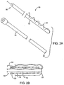
- a first exemplary system 10 for performing the present methods comprises a sleeve-like length of material 12 and a tubular guide 14, as shown in FIGS. 2A and 2B .
- the sleeve-like length of material 12 has a trailing end 16 and an anchor end 18.
- the length of the sleeve-like length of material will typically be in the range from 1 cm to 10 cm, usually from 2 cm to 6 cm, although much longer lengths may find use in different circumstances.
- the sleeve will usually have a continuous sidewall with no openings (other than at the trailing end 16 and anchor end 18), but could also have open regions, have a loose weave in the case of woven materials, or otherwise have openings or discontinuities in the sidewall without departing from the present principles.
- the sleeve-like length of material 12 may be arranged so that it is initially within a central passage 20 of the tubular guide 14.
- the material 12 can be arranged so that the anchor end 18 of the sleeve-like length of material 12 will initially be on the exterior of the tubular guide 14 and generally held stationary as the tubular guide is advanced.
- the trailing end 16 is everted over the distal end 22 of the guide member, generally as shown in FIG. 2B .
- the trailing end 16 will usually include a tension member 24 which may be a suture, filament, thin wire, or other element which is attached at or near the terminus of the trailing end 16 and which preferably is woven and out of the material 12 over at least a portion of the length of material 12. Such woven or pleated structures will be described in more detail hereinbelow. Pulling on the tension member 24 will collapse and compact the length of material 12 in order to provide the desired luminal occlusion.
- a tension member 24 which may be a suture, filament, thin wire, or other element which is attached at or near the terminus of the trailing end 16 and which preferably is woven and out of the material 12 over at least a portion of the length of material 12.
- woven or pleated structures will be described in more detail hereinbelow. Pulling on the tension member 24 will collapse and compact the length of material 12 in order to provide the desired luminal occlusion.
- FIGS. 3A-3H use of the system 10 for removing a kidney stone KS from a lumen L of a ureter U will be described.
- access is gained to the os O of the bladder B ( FIG. 1 ) in a conventional manner.
- the tubular guide 14 will then be passed through the os O and into the lumen L of the ureter with the anchor end 18 of the sleeve-like member 12 being held stationary relative to the os.
- the tubular guide 14 is advanced so that the sleeve-like length of material 12 everts from the distal end 22 of the guide.
- the sleeve-like length of material 12 will continue to be everted, but will have an exposed surface 13 which remains generally stationary relative to the inner wall of the ureter U and the exterior of the kidney stone KS.
- Such eversion of the sleeve-like length of material 12 acts like a "tractor tread" in allowing the tubular guide 12 to bypass the kidney stone, as illustrated in FIG. 3C .
- the eversion of the length of material 12 also reduces the risk of perforation or other trauma to the ureter.
- the tubular guide 14 will continue to be advanced through the lumen L in the distal direction (toward the kidney K) until the trailing end 16 has been partly or fully exposed so that the region including the tension member 24 lies distal to the kidney stone KS.
- the tubular guide 14 will be at least partly withdrawn in a proximal direction so that its distal end 22 is located proximal of the kidney stone KS, as shown in FIG. 3E .
- the portion of the sleeve-like member 12 which lies distal to the kidney stone will radially collapse (since its internal support has been withdrawn) leaving a slack "hell" having the tension member 24 laced therethrough in place.
- tension member 24 By drawing in a proximal direction (arrow 30) on tension member 24, the trailing end 16 of the sleeve-like member 12 will be caused to axially collapse, generally in the manner of an accordion, as shown in FIG. 3F .
- the trailing end 16 of the sleeve-like member 12 will be fully compacted against a distal surf ace of the kidney stone KS, as shown in FIG. 3G .
- the compacted trailing end 12 of the sleeve-like length of material will draw the kidney stone in a proximal direction toward the bladder, as shown in FIG. 3H .
- FIG. 4A and 4B it will also be possible to additionally compact a portion of the sleeve-like length of material 12 against the proximal or bladder-side of the stone S prior to fragmentation and/or removal.
- the trailing end 16 of the sleeve-like member 12 is compacted, as generally described above and shown in FIG. 4A .
- an additional length 36 of the sleeve-like length of material 12 will be allowed to collapse.
- That additional collapsed section may then be compacted against the proximal side of the kidney stone by either further drawing on the tension member 24 (moving the stone proximally) or by simply advancing the tubular guide 14 and collapsed sleeve in a distal direction. Either way, a proximal portion 36 of the sleeve-like length of material 12 will be compacted, as shown in FIG. 4B .
- Lithotripsy or other energy-based disruption of the kidney stone KS may then be performed with loss of the fragments in either direction being inhibited.
- the kidney stone and/or resulting fragments may then be withdrawn from the ureter U as generally described above, except that the stone/fragments will be substantially encapsulated by the sleeve-like material.
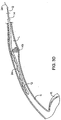
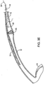
- System 40 comprises an advancement member 42 and a ribbon-like length of material 44.
- the advancement member may be a solid-core wire, a tube, or other small diameter or flat/thin member having sufficient column strength to permit its advancement through body lumen and preferably past an obstruction, such as a kidney stone in a ureter.
- the advancement member may be in the form of a guidewire of the type commonly used in urological procedures.
- the ribbon-like length of material 44 may be composed of any of the materials listed previously and may have a length in the ranges set forth above.
- the length of material 44 will typically consist of only a single layer with a width in the range from 1 mm to 10 mm, usually from 2 mm to 6 mm, and a thickness of 1 mm or less.
- the ribbon-like length of material 44 will comprise a flattened tube or other multiple-layer or laminated structure instead of a single layer as illustrated.
- the ribbon-like length of material 44 may also have a plurality of axially spaced-apart fold structures 46 disposed over at least a distal length thereof.
- a distal end 48 of the length of material 44 will be attached at or near a distal end of the advancement member 42 so that the advancement member can pull or otherwise carry the ribbon-like length of material through the target body lumen as it is advanced.
- the advancement member 42 can be penetrated or "laced” through axially spaced-apart locations on the ribbon-like length of material 44. As illustrated, the lacing occurs through consecutive sections defined by the fold structures 46. In both cases, the advancement member 42 will be used to advance at least a portion of the ribbon 44 past a stone KS or other object to be retrieved or stabilized.
- the deployment system 40 of FIG. 5A is introduced by advancing advancement member 42 through the os O ( FIG. 1 ) and into the lumen of the ureter U, as shown in FIG. 6A .
- the advancement member 42 carries the ribbon-like length of material 44 distally within the lumen and past the kidney stone KS as shown in FIG. 6B .
- the advancement member 42 may be drawn in the proximal direction, as shown in FIG. 6C , while the proximal portion of the ribbon-like length of material 44 is left in place. In this way, a region 50 of the ribbon-like length of material 44 which is distal to the kidney stone KS, as shown in FIG.
- the compacted structure 52 may then be used in any of the ways described previously, including for moving and/or removing the kidney stone into the bladder, stabilizing the kidney stone during lithotripsy, optionally combined with the removing the fragments of the kidney stone into the bladder, or the like.
- any of the material compaction systems 10 and 40 have been shown to be directly introduced, i.e. introduced without an external sheath or other introducing member. As shown in FIGS. 7A and 7B , however, any of the material compaction systems may be introduced through a sheath 70 which is first introduced into the lumen of the ureter U in a conventional manner.
- the sheath 70 may be a simple tubular sheath or could be an everting-sleeve sheath. In any event, once the sheath 70 is in place past the kidney stone KS, the sheath may be withdrawn leaving the material compaction system in place.
- System 10 is illustrated, but system 40 or any other systems according to the present disclosure could be introduced through the sheath. Once the system 10 is in place, it may be foreshortened by drawing on tension member 24 using the resulting compacted component in any of the ways described previously.
- a guidewire-element can be used as the advancement member.
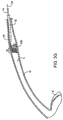
- an apparatus 100 comprises a guidewire 102 having a tubular length of material 104 attached at its distal end 106.
- a distal region 108 (shown in broken line) of the tubular length of material 104 may be expanded, slit, braided, or otherwise modified so that it assumes a larger structure or mass when axially compacted in accordance with the principles of the present disclosure.
- the apparatus of FIG. 8 may be modified to include a stiffening tube 110 which may be slid over the proximal end of the guidewire 102.
- This stiffening tube is advantageous in that it can improve pushability of the guidewire to advance past difficult obstructions in a body lumen. Once the guidewire is past the obstruction, the stiffening tube can be partially or wholly withdrawn, leaving the smaller guidewire 102 in place. It will be appreciated that with the apparatus 100 shown in both FIGS. 8 and 9 , the guidewire can be utilized for advancing catheters or other tools thereover when the length of material 104 is in its elongated, low profile configuration.
- a further apparatus 120 comprises a guidewire-like advancement member 122, a tubular guide member 124, and a tubular length of material 126.
- the tubular length of material 126 is attached at its distal end 128 to the guidewire and at its proximal end 130 to the tubular guide member 124.
- the attachment may be as shown in FIG. 11A where a ring 132 clamps the tubular length of material 126 over necked down region 134 of the tubular guide member 124.
- a clamping ring 140 may be provided within the distal end of the lumen of the tubular guide member 124, as shown in FIG. 11B .
- the tubular length of material 126 may be elongated by advancing the advancement member 122 distally relatively to the tubular guide member 124.
- the length of material 126 maybe compacted into its expanded mass, as shown in broken line in FIG. 10 , by drawing the advancement member proximally relative to the tubular guide member 124.
- the tubular guide 126 may be either elongated, as shown in FIG. 10 , withdrawn into the lumen of the tubular guide member 124, or folded back over the exterior lumen of the guide member 124, as shown in FIG. 12 .
- the apparatus 150 comprises a guidewire-like advancement member 152, a tubular guide 154, and a distal end 160 of the length of materials attached to the distal end of the guide tube.
- the guide tube can be advanced over the separate guidewire 152 (having a removable hub 162).
- the length of material 156 can then be enlarged into an occlusive mass by pulling proximally on the guide tube 154.
- the occlusive mass may be straightened and elongated by pulling proximally on the ring 158.
Landscapes
- Health & Medical Sciences (AREA)
- Life Sciences & Earth Sciences (AREA)
- General Health & Medical Sciences (AREA)
- Surgery (AREA)
- Public Health (AREA)
- Animal Behavior & Ethology (AREA)
- Engineering & Computer Science (AREA)
- Biomedical Technology (AREA)
- Heart & Thoracic Surgery (AREA)
- Veterinary Medicine (AREA)
- Nuclear Medicine, Radiotherapy & Molecular Imaging (AREA)
- Molecular Biology (AREA)
- Medical Informatics (AREA)
- Hematology (AREA)
- Anesthesiology (AREA)
- Pulmonology (AREA)
- Vascular Medicine (AREA)
- Orthopedic Medicine & Surgery (AREA)
- Dentistry (AREA)
- Otolaryngology (AREA)
- Oral & Maxillofacial Surgery (AREA)
- Biophysics (AREA)
- Surgical Instruments (AREA)
- Prostheses (AREA)
Description
- The present invention relates generally to medical apparatus. More particularly, the present invention relates to apparatus for deploying conformable structures in the ureter and other body lumens.
- It is common for kidney stones to pass from the kidney through the ureter to the urinary bladder. While muscular peristalsis of the ureter will often pass the stones into the bladder without complication, in some instances large and/or irregularly shaped stones may become lodged within the ureter causing discomfort and potential damage to the ureter and upper collective system.
- A number of ways have been proposed for dislodging such kidney stones. For example, extracorporeal shock wave lithotripsy (ESWL) can be used to break up the kidney stones but is often ineffective when the stones are present in the ureter. Moreover, ESWL can produce irregularly-shaped fragments which, while smaller than the original stone, may have sharp edges that will prevent spontaneous passage of the particles through the ureter. In the case of a stone or fragment, impacted in the ureter, it is common practice to attempt capture, using a wire stone basket. The basket is introduced through a ureteroscope which itself is typically introduced retrograde through the urinary tract.
- In many cases, further lithotripsy through the scope is performed (ISWL). It is often difficult to advance such stone baskets past the obstructing material. Attempts to pass wire baskets or other grasping apparatus past a stone lodged in the ureter also presents risk of damage to the ureter. Abrasion, stretching, or perforation of the ureter at the impaction site can cause local urine leakage or edema even if the stone or resulting debris is successfully captured; and removal of the basket with the stone may be quite difficult. In some instances, baskets containing captured stones or fragments cannot themselves be removed, and it is difficult if not impossible to release the captured stone material back into the lumen of the ureter. In those cases, the basket must often be retrieved surgically. Finally, if and/or when ISWL is performed, it would be useful to have some means of stabilizing stone fragments at the treatment site, rather than letting them escape up the ureter in a retrograde direction.
- For these reasons, it would be desirable to provide improved methods and apparatus for capturing and removing kidney stones from the ureter. It would be further desirable if the methods and apparatus were useful for containing and/or retrieving other materials from other body lumens, such as for extracting clot, thrombus, and/or other obstructing materials from blood vessels in embolectomy procedures. It would still further be desirable if the methods and apparatus were useful for still other procedures, including luminal occlusion, for example vascular occlusion for hemostasis, restricting blood flow to target tissue regions, and the like. The methods and apparatus should be generally atraumatic in use, require significantly less skill than basket manipulation, optionally allow the release of captured material, should be simple and economical in construction and use, and should provide minimum risk and trauma to the patient. At least some of these objectives will be met by the invention described hereinbelow.
- The use of an everting sleeve composed of thin, tensilized polytetrafluoroethylene for introducing catheters to body lumens is described in
U.S. Patent Nos. 5,531,717 ;5,676,688 ;5,711,841 ;5,897,535 ;6,007,488 ;6,240,968 ; andEP605427B1 U.S. application No. 2003/0120281 . -
US 4706671 discloses a catheter having the features of the preamble of the appended Claim 1.US 5192286 shows a collapsible net at the distal end of a catheter which may be opened in a body lumen to capture deleterious materials.WO 2005/110244 A1 , which was published after the filing date of the present application and therefore is not relevant to the question of inventive step, discloses apparatus and methods for positioning and securing anchors into or upon tissue. - The present invention is apparatus as defined in Claim 1 of the appended claims. Certain embodiments of the invention are set out in the dependent claims.
- The present invention provides apparatus for deploying an occluding structure in a body lumen. The occluding structure will usually be intended for temporary placement and will often be used for removing kidney stones and other urinary calculi, blood clots, thrombus, and other materials which obstruct body lumens. In other instances, however, the occluding structures could be deployed permanently for occluding blood vessels, fallopian tubes, and the like for a variety of purposes, particularly when the occluding structure is lodged in a lumen having a diameter which decreases in the direction of blood or other fluid flow.
- The occluding structure typically comprises a length of material which is initially positioned in the body lumen in a generally elongate or unfurled configuration. The length of material is subsequently pulled, furled, or drawn back on itself so that the material compresses or compacts into the desired occluding structure. The material typically comprises a polymer film, a woven fabric, a non-woven fabric, and composites and laminates thereof. Exemplary polymer materials include polytetrafluoroethylene (PTFE), polyethylene (PE), perfluoroalkoxy (PFA), polyurethane (PU), perfluoromethylvinylether (MFA), and perfluoropropylvinylether (PPVE). Other exemplary materials include films, fabrics woven of any supple material such as nylon, polyester, silk, etc., lamination of these materials, and the like. The materials will generally be chosen so that they compress or compact into a relatively soft, non-traumatic mass of material. The compaction may be by folding, twisting, spiraling, or otherwise collapsing so that the length of the material becomes shorter and the width becomes greater, where length is a dimension generally aligned with the axis of the body lumen and width is the dimension generally transverse to the axis when the material is in the body lumen. The length of material is ribbon-like, capable of being collapsed and compacted. The material may be formed from a tube by expansion, weaving, braiding, or slitting. In exemplary embodiments, the length of material prior to compaction is in the range from 1 cm to 10 cm, usually from 2 cm to 6 cm, and most typically from 3 cm to 5 cm. The original length will be foreshortened so that the resulting compacted mass has a width that approximates the internal diameter of the lumen in the range from 1 mm to 10 mm, usually from 2 mm to 6 mm, and preferably from 3 mm to 5 mm.
- By deploying the length of material in its elongated, narrow-diameter configuration, the material will have a very low profile which permits it to be advanced through narrow body lumens, and more particularly, past obstruction(s) which may be present within the lumen, along the way bypassing structures, valves, sphincters, etc. For example, the length of material may be deployed past stones and other urinary calculi, past blood clots, past regions of thrombosis in blood vessels, and the like. By then compacting the length of material on a distal side of the obstruction, the compacted material may then be drawn in a proximal direction to form a relatively stiff plug or occlusion which is drawn proximally in order to move or more usually remove the obstruction from the body lumen. Deployment of the occluding member, however, may be used for other purposes, including containment of materials, e.g., stone debris during lithotripsy and distal protection against the release of emboli in performing vascular procedures; hemostasis when deployed in blood vessels; contraception when deployed in the fallopian tubes; and the like.
- In some instances, the devices of the present disclosure may be used as guidewires when the length of material is in its elongated, narrow-diameter configuration. In particular, in some cases a tubular length of material may be attached to an advancement member which has many of the features of a guidewire, including a pushable, torquable shaft and a floppy distal tip to allow steering through a body lumen.
- The apparatus may be used in a method for compacting a structure in a body lumen which comprises advancing a length of material distally in the body lumen and drawing a distal location on the advanced length of material proximally to compact the material into a structure which at least partially occludes the body lumen. Typically, the length of material is advanced distally past an obstruction in the body lumen and thereafter drawn proximally against the obstruction. The obstruction may then be moved by pulling or drawing the compacted material against the obstruction to reposition the obstruction within or outside of the body lumen. Additionally or alternatively, the compacted structure may prevent the obstruction from moving in a distal direction without movement or removal of the material. In a specific example, the body lumen is a ureter, cystic duct, or common bile duct, and the obstruction comprises one or more stones or other calculi. In a more specific example, the body lumen is a ureter and the length of material is advanced from the urinary bladder into the ureter and past the kidney stone(s) lodged within. Optionally, energy may be directed to disrupt the kidney stones while engaged by the compacted material.
- The length of material may be advanced in a variety of ways. For example, the length of material may be advanced or otherwise introduced through a tubular guide. In one instance, the tubular guide is first positioned through the body lumen and the length of material is advanced therethrough, typically using a separate advancement member. In a second instance, the tubular guide and the length of material are introduced simultaneously. Note that the tubular guide may subsequently be drawn proximally in order to expose an unsupported portion of the material. In a third instance, the length of material is advanced using an advancement member. The length of material is attached at or near a distal end of the advancement member, such as a guidewire, and the advancement member and length of material are simultaneously introduced through the body lumen and optionally past an obstruction. In a fourth and presently preferred instance, the tubular guide is introduced through the body lumen where a length of material is originally carried within the interior of the tubular guide. The length of material is everted over a distal end of the tube as the tube is introduced and acts as a barrier to protect the wall of the body lumen since the everted material will remain generally stationary relative to the wall. In the latter instance, the length of material is typically in the form of a sleeve which emerges from an interior lumen, passage, or receptacle of the tubular guide to cover an exterior of the tubular guide as the tubular guide is advanced and the sleeve everts.
- In some instances, the tubular guide or other advancement member will also be used to draw back the advanced length of material proximally to compact the material into the occluding structure. In such instances, the systems used to perform the present methods may consist only of the length of material and the tubular guide or other advancement member, e.g., a guidewire-like advancement member as described previously. More usually, however, the systems will include at least a third component which comprises a tension member for drawing proximally on the length of material after it has been advanced by the tubular guide or other advancement member. The tension member may have a wide variety of forms and may comprise suture, filament, a thread, a wire, a tube, or other elongate element that can be permanently or releasably attached to a distal location on the length of material. Frequently, the tension member will be woven, threaded, or otherwise incorporated into the length of material to facilitate the compaction of the material as the tension member is pulled backward. In an illustrated embodiment, the tension member is a filament which is woven in and out of axially spaced-apart locations on the length of material to permit folding of the length of material as the tension member is drawn proximally. The tension member could alternatively pass through loops or other attachment points on the length of material or could be woven in as part of the fabric of the length of material. Alternately, the tension member could pass through the lumen of a tubular sleeve of the material. In still other alternate configurations, the tension member may pass through the center of a tubular sleeve of collapsible material and loop around the distal end of the sleeve. The tension member can then pass back along the outside of the sleeve to form a loop over the sleeve where pulling on either or both ends of the loop will collapse the material to form the expanded material mass.
- When using a separate tension member, the methods of use may comprise detaching the tension guide or other advancement member from the length of material prior to compacting the material. Alternatively, when using a tubular guide disposed within a sleeve-like length of material, the tubular guide may be partially withdrawn in a proximal direction leaving a distal portion of the length of material unsupported and ready for compaction. In many cases, it will be possible to reverse compaction of the length of material by distally advancing the tension member prior to detachment. For example, it may be desirable under certain circumstances to reverse compaction to release entrapped materials that cannot be removed. By releasing and recapturing, removal could be completed.
- In a particular embodiment, the distal end of the length of material may be attached at or near the distal end of an advancing member, e.g. immediately proximally of the floppy tip of a guidewire-like advancement member. The proximal end of the length of material may be attached to a tubular guide through which the advancement member can be advanced and retracted. By advancing the advancement member in the distal direction relative to the tubular guide, the length of material (which will itself typically be in a tubular form) will be lengthened and elongated to its narrow diameter configuration. Conversely, by drawing the advancement member proximally relative to the tension member, the length of material will be expanded into an occlusive mass. An advantage of this configuration is that the tubular guide may replace a portion of the length of the "length of material" while still allowing the material to be readily manipulated when advanced well into a body lumen.
- In certain embodiments, the length of material will comprise fold structures such as lines or other scored notched, or weakened regions or variations in thickness or geometry which impart a preferential folding pattern upon drawing the length of material in the proximal direction. Preferred materials have been set forth above.
- In an example of a method for introduction, a sleeve-like length of material is introduced using a tubular guide. The sleeve material is initially stowed within a central lumen or other passage or receptacle in the tubular guide. A first end of the sleeve is immobilized relative to an entry point into the body lumen being treated. The tubular guide is then advanced in a distal direction, and the length of material emerges from a distal end of the tube and everts so that the sleeve material covers the inner wall of the body lumen. Thus, as the apparatus is introduced, the length of material acts as a protective barrier to reduce trauma to the wall of the body lumen. It may further act to facilitate passage of the device past any stones or other obstructions which are present in the body lumen. Pulling back on the tubular guide and/or the tension member with tubular guide in distal position will reverse advancement of the tubular guide. Finally, after the apparatus has been introduced a sufficient distance beyond any obstruction or other target location, the tubular guide may be withdrawn proximally from the sleeve until it is proximal to the obstruction. The sleeve can then be pulled back to provide the compacted material which is useful for removal of the obstruction, temporary or permanent occlusion of the body lumen, hemostasis, or other purposes. Pulling back the sleeve could be accomplished using the tubular guide, itself, but will more usually be accomplished using a separate tension member as described above.
- The present invention provides apparatus useful for performing the methods just described. The apparatus may comprise a length of material and a tension member attached to a distal location on the length of material. The tension member will be adapted to compact the material into an occluding structure when the member is pulled proximally relative to the length of material when present in the body lumen. Frequently, the apparatus will further comprise a tubular guide or other advancement member for facilitating introduction of the apparatus into the target body lumen. Other aspects of the apparatus have been described above in connection with the methods of use of the present disclosure.
-
-
FIG. 1 illustrates a ureter having a kidney stone lodged between the kidney and bladder. -
FIGS. 2A and 2B illustrate an example of a first apparatus which comprises a sleeve-like length of material, a tubular guide, and a tension member. -
FIGS. 3A-3H illustrate use of the apparatus ofFIGS. 2A and 2B for removing a kidney stone from a ureter. -
FIGS. 4A and 4B illustrate a variation in the protocol of the method ofFIGS. 3A-3H . -
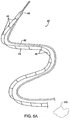
FIG. 5A illustrates a second apparatus constructed in accordance with the principles of the present invention consisting of a length of material and a separate advancement member. -
FIG. 5B illustrates a third apparatus similar to the second apparatus ofFIG. 5A , except that the advancement member is threaded through a portion of the ribbon-like length of material. -
FIGS. 6A-6C illustrate use of the apparatus ofFIG. 5A in accordance with the principles of the present invention. -
FIGS. 7A and 7B illustrate a modified protocol according to the principles of the present invention. -
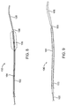
FIG. 8 illustrates apparatus having a guidewire-like advancement member. -
FIG. 9 illustrates apparatus similar to that shown inFIG. 8 , but further including a stiffening tube which may be slidingly advanced over a proximal portion of the guidewire. -
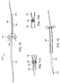
FIG. 10 illustrates apparatus comprising a guidewire-like advancement member, a tubular sheath, and a tubular length of material connected between the advancement member and tubular sheath. -
FIGS. 11A and 11B illustrate alternative detailed constructions taken along line 11-11 ofFIG. 10 . -
FIG. 12 illustrates one possible manner in which the length of material of the apparatus ofFIG. 10 may be stowed. -
FIG. 13 illustrates a further apparatus where the length of material may be tensioned directly from its proximal end. - The methods and apparatus of the present disclosure are useful for intervening in any body lumen of a patient where it is desired to temporarily or permanently occlude at least a portion of the lumen. Most commonly, the methods will be used to move or remove an obstruction from the body lumen, but the methods will also find use in stabilizing such obstructions, particularly while the obstructions are undergoing other treatments such as lithotripsy; preventing distal embolization in vascular procedures; providing temporary or permanent hemostasis in the vasculature; treating aneurysms, particularly in the cerebral vasculature; providing contraception by occlusion of the fallopian tubes; and the like. Thus, potential target body lumens include the urinary tract, particularly the ureter; the vasculature, including the cerebral, peripheral, and coronary vasculature; the fallopian tubes, and the like. The following description is directed particularly at the removal of kidney stones from the ureter, but it will be appreciated that the principles described will apply more broadly as discussed above.
- Referring now to
FIG. 1 , the present invention may be used for engaging and retrieving a kidney stone KS or fragments from a ureter U between a kidney K and a bladder B. Access to the bladder will be through the urethra UA using conventional access devices which will not be described herein. Access to the ureter U will be through the os O in a wall of the bladder leading into the lumen of the ureter. - A first
exemplary system 10 for performing the present methods comprises a sleeve-like length ofmaterial 12 and atubular guide 14, as shown inFIGS. 2A and 2B . The sleeve-like length ofmaterial 12 has a trailingend 16 and ananchor end 18. The length of the sleeve-like length of material will typically be in the range from 1 cm to 10 cm, usually from 2 cm to 6 cm, although much longer lengths may find use in different circumstances. The sleeve will usually have a continuous sidewall with no openings (other than at the trailingend 16 and anchor end 18), but could also have open regions, have a loose weave in the case of woven materials, or otherwise have openings or discontinuities in the sidewall without departing from the present principles. - Referring now in particular to
FIG. 2B , the sleeve-like length ofmaterial 12 may be arranged so that it is initially within acentral passage 20 of thetubular guide 14. The material 12 can be arranged so that theanchor end 18 of the sleeve-like length ofmaterial 12 will initially be on the exterior of thetubular guide 14 and generally held stationary as the tubular guide is advanced. As thetubular guide 14 is advanced through the body lumen, the trailingend 16 is everted over thedistal end 22 of the guide member, generally as shown inFIG. 2B . The trailingend 16 will usually include atension member 24 which may be a suture, filament, thin wire, or other element which is attached at or near the terminus of the trailingend 16 and which preferably is woven and out of the material 12 over at least a portion of the length ofmaterial 12. Such woven or pleated structures will be described in more detail hereinbelow. Pulling on thetension member 24 will collapse and compact the length ofmaterial 12 in order to provide the desired luminal occlusion. - Referring now to
FIGS. 3A-3H , use of thesystem 10 for removing a kidney stone KS from a lumen L of a ureter U will be described. Initially, access is gained to the os O of the bladder B (FIG. 1 ) in a conventional manner. Thetubular guide 14 will then be passed through the os O and into the lumen L of the ureter with theanchor end 18 of the sleeve-like member 12 being held stationary relative to the os. - Referring now to
FIG. 3B , thetubular guide 14 is advanced so that the sleeve-like length ofmaterial 12 everts from thedistal end 22 of the guide. As the evertingend 23 of thetubular guide 14 approaches the kidney stone KS, the sleeve-like length ofmaterial 12 will continue to be everted, but will have an exposedsurface 13 which remains generally stationary relative to the inner wall of the ureter U and the exterior of the kidney stone KS. Such eversion of the sleeve-like length ofmaterial 12 acts like a "tractor tread" in allowing thetubular guide 12 to bypass the kidney stone, as illustrated inFIG. 3C . In addition to facilitating bypass of the kidney stone KS, the eversion of the length ofmaterial 12 also reduces the risk of perforation or other trauma to the ureter. - Referring now to
FIG. 3D , once past the kidney stone KS, thetubular guide 14 will continue to be advanced through the lumen L in the distal direction (toward the kidney K) until the trailingend 16 has been partly or fully exposed so that the region including thetension member 24 lies distal to the kidney stone KS. - At this point, the
tubular guide 14 will be at least partly withdrawn in a proximal direction so that itsdistal end 22 is located proximal of the kidney stone KS, as shown inFIG. 3E . The portion of the sleeve-like member 12 which lies distal to the kidney stone will radially collapse (since its internal support has been withdrawn) leaving a slack "hell" having thetension member 24 laced therethrough in place. By drawing in a proximal direction (arrow 30) ontension member 24, the trailingend 16 of the sleeve-like member 12 will be caused to axially collapse, generally in the manner of an accordion, as shown inFIG. 3F . By continuing to draw on thetension member 24 the trailingend 16 of the sleeve-like member 12 will be fully compacted against a distal surf ace of the kidney stone KS, as shown inFIG. 3G . By then pulling on any or all of the sleeve-like member 12,tubular guide 14, andtension member 24 in a proximal direction, the compacted trailingend 12 of the sleeve-like length of material will draw the kidney stone in a proximal direction toward the bladder, as shown inFIG. 3H . Note that at any time after the trailingend 16 had been compacted, it would have been possible to apply laser or other energy in order to fragment the kidney stone and further facilitate its withdrawal. The presence of the compacted trailingend 16 would help prevent loss of the resulting stone fragments into the kidney. - Referring now to
FIG. 4A and 4B , it will also be possible to additionally compact a portion of the sleeve-like length ofmaterial 12 against the proximal or bladder-side of the stone S prior to fragmentation and/or removal. Initially, the trailingend 16 of the sleeve-like member 12 is compacted, as generally described above and shown inFIG. 4A . By then further withdrawing the guide member in a proximal direction toward the bladder, anadditional length 36 of the sleeve-like length ofmaterial 12 will be allowed to collapse. That additional collapsed section may then be compacted against the proximal side of the kidney stone by either further drawing on the tension member 24 (moving the stone proximally) or by simply advancing thetubular guide 14 and collapsed sleeve in a distal direction. Either way, aproximal portion 36 of the sleeve-like length ofmaterial 12 will be compacted, as shown inFIG. 4B . Lithotripsy or other energy-based disruption of the kidney stone KS may then be performed with loss of the fragments in either direction being inhibited. The kidney stone and/or resulting fragments may then be withdrawn from the ureter U as generally described above, except that the stone/fragments will be substantially encapsulated by the sleeve-like material. - Referring now to
FIG. 5A , a construction of the apparatus of an embodiment of the present invention will be described.System 40 comprises anadvancement member 42 and a ribbon-like length ofmaterial 44. The advancement member may be a solid-core wire, a tube, or other small diameter or flat/thin member having sufficient column strength to permit its advancement through body lumen and preferably past an obstruction, such as a kidney stone in a ureter. For example, the advancement member may be in the form of a guidewire of the type commonly used in urological procedures. The ribbon-like length ofmaterial 44 may be composed of any of the materials listed previously and may have a length in the ranges set forth above. The length ofmaterial 44 will typically consist of only a single layer with a width in the range from 1 mm to 10 mm, usually from 2 mm to 6 mm, and a thickness of 1 mm or less. Optionally, the ribbon-like length ofmaterial 44 will comprise a flattened tube or other multiple-layer or laminated structure instead of a single layer as illustrated. The ribbon-like length ofmaterial 44 may also have a plurality of axially spaced-apart foldstructures 46 disposed over at least a distal length thereof. Adistal end 48 of the length ofmaterial 44 will be attached at or near a distal end of theadvancement member 42 so that the advancement member can pull or otherwise carry the ribbon-like length of material through the target body lumen as it is advanced. Optionally, as shown inFIG. 5B , theadvancement member 42 can be penetrated or "laced" through axially spaced-apart locations on the ribbon-like length ofmaterial 44. As illustrated, the lacing occurs through consecutive sections defined by thefold structures 46. In both cases, theadvancement member 42 will be used to advance at least a portion of theribbon 44 past a stone KS or other object to be retrieved or stabilized. - In use, the
deployment system 40 ofFIG. 5A is introduced by advancingadvancement member 42 through the os O (FIG. 1 ) and into the lumen of the ureter U, as shown inFIG. 6A . Theadvancement member 42 carries the ribbon-like length ofmaterial 44 distally within the lumen and past the kidney stone KS as shown inFIG. 6B . After the desired distal positioning has been achieved, theadvancement member 42 may be drawn in the proximal direction, as shown inFIG. 6C , while the proximal portion of the ribbon-like length ofmaterial 44 is left in place. In this way, aregion 50 of the ribbon-like length ofmaterial 44 which is distal to the kidney stone KS, as shown inFIG. 6B , may be simultaneously or sequentially compacted into the foreshortened occludingstructure 52, as shown inFIG. 6C . The compactedstructure 52 may then be used in any of the ways described previously, including for moving and/or removing the kidney stone into the bladder, stabilizing the kidney stone during lithotripsy, optionally combined with the removing the fragments of the kidney stone into the bladder, or the like. - As described thus far, the
material compaction systems FIGS. 7A and 7B , however, any of the material compaction systems may be introduced through asheath 70 which is first introduced into the lumen of the ureter U in a conventional manner. Thesheath 70 may be a simple tubular sheath or could be an everting-sleeve sheath. In any event, once thesheath 70 is in place past the kidney stone KS, the sheath may be withdrawn leaving the material compaction system in place.System 10 is illustrated, butsystem 40 or any other systems according to the present disclosure could be introduced through the sheath. Once thesystem 10 is in place, it may be foreshortened by drawing ontension member 24 using the resulting compacted component in any of the ways described previously. - In certain embodiments of the present invention, a guidewire-element can be used as the advancement member. As shown in
FIG. 8 , anapparatus 100 comprises aguidewire 102 having a tubular length ofmaterial 104 attached at itsdistal end 106. Optionally, a distal region 108 (shown in broken line) of the tubular length ofmaterial 104 may be expanded, slit, braided, or otherwise modified so that it assumes a larger structure or mass when axially compacted in accordance with the principles of the present disclosure. - Referring now to
FIG. 9 , the apparatus ofFIG. 8 may be modified to include astiffening tube 110 which may be slid over the proximal end of theguidewire 102. This stiffening tube is advantageous in that it can improve pushability of the guidewire to advance past difficult obstructions in a body lumen. Once the guidewire is past the obstruction, the stiffening tube can be partially or wholly withdrawn, leaving thesmaller guidewire 102 in place. It will be appreciated that with theapparatus 100 shown in bothFIGS. 8 and 9 , the guidewire can be utilized for advancing catheters or other tools thereover when the length ofmaterial 104 is in its elongated, low profile configuration. - Referring now to
FIG. 10 , afurther apparatus 120 comprises a guidewire-like advancement member 122, atubular guide member 124, and a tubular length ofmaterial 126. The tubular length ofmaterial 126 is attached at itsdistal end 128 to the guidewire and at itsproximal end 130 to thetubular guide member 124. The attachment may be as shown inFIG. 11A where aring 132 clamps the tubular length ofmaterial 126 over necked downregion 134 of thetubular guide member 124. Alternatively, aclamping ring 140 may be provided within the distal end of the lumen of thetubular guide member 124, as shown inFIG. 11B . - In the
apparatus 120, the tubular length ofmaterial 126 may be elongated by advancing theadvancement member 122 distally relatively to thetubular guide member 124. Alternatively, the length ofmaterial 126 maybe compacted into its expanded mass, as shown in broken line inFIG. 10 , by drawing the advancement member proximally relative to thetubular guide member 124. For introduction, thetubular guide 126 may be either elongated, as shown inFIG. 10 , withdrawn into the lumen of thetubular guide member 124, or folded back over the exterior lumen of theguide member 124, as shown inFIG. 12 . - Referring now to
FIG. 13 , still anotherapparatus 150 is illustrated. Theapparatus 150 comprises a guidewire-like advancement member 152, atubular guide 154, and adistal end 160 of the length of materials attached to the distal end of the guide tube. In this way, the guide tube can be advanced over the separate guidewire 152 (having a removable hub 162). The length ofmaterial 156 can then be enlarged into an occlusive mass by pulling proximally on theguide tube 154. Alternatively, the occlusive mass may be straightened and elongated by pulling proximally on thering 158. - While the above provides a complete description of the preferred embodiments of the invention, various alternatives, modifications, and equivalents may be used. Therefore, the above description should not be taken as limiting the scope of the invention which is defined by the appended claims.
Claims (16)
- Apparatus for deploying a conformal structure in a body lumen, said apparatus comprising:a length of polymer film or fabric material (44); anda tension member (42) attached to a distal location on the length of material, the tension member having sufficient column strength to advance the length of material distally in the body lumen by distal movement of the tension member, said tension member being incorporated into the length of material and adapted to compact the material into an occluding structure when the member is pulled proximally relative to the length of material when present in a body lumen (L);the apparatus characterised in that the length of polymer film or fabric material is ribbon-like.
- Apparatus as in claim 1, wherein the material is selected from the group consisting of polymer films, woven fabrics, non-woven fabrics, and composites and laminates thereof.
- Apparatus as in claim 1 or 2, wherein the tension member is embedded within the length of material.
- Apparatus as in claim 1 or 2, wherein the tension member penetrates the length of material at multiple spaced-apart locations along the length.
- Apparatus as in claim 4, wherein the length of material has fold structures (46) between at least some of the spaced-apart locations.
- Apparatus as in claim 1 or 2, wherein the tension member is positioned in a plurality of connecting loops disposed at multiple spaced-apart locations along the length of material.
- Apparatus as in claim 1 or 2, wherein the tension member is positioned in a substantially continuous passage formed in or on the length of material.
- Apparatus as in claim 1 or 2, wherein the tension member comprises a filament woven into the length of material.
- Apparatus as in claim 1 or 2, wherein the tension member is attached only at a distal end of the length of material.
- Apparatus as in claim 1 or 2, wherein the tension member comprises a guide wire structure.
- Apparatus as in claim 1 or 2, further comprising an advancement member coupled to the length of material.
- Apparatus as in claim 11, wherein a distal location on the length of material is frangibly attached to a distal location on the advancement member.
- Apparatus as in claim 11, wherein the advancement member comprises a wire.
- Apparatus as in claim 11, wherein the advancement member comprises a tubular guide.
- Apparatus as in claim 14, wherein the length of material is disposed in a lumen of the tubular guide so that the material is deployed by everting from a distal end of the guide as the guide is advanced through the body lumen.
- Apparatus as in claim 14, wherein the length of material is disposed to be separately passed through a lumen of the tubular guide.
Applications Claiming Priority (2)
| Application Number | Priority Date | Filing Date | Title |
|---|---|---|---|
| US10/886,886 US7462183B2 (en) | 2004-07-07 | 2004-07-07 | Methods for deploying conformed structures in body lumens |
| PCT/US2005/023988 WO2006014491A2 (en) | 2004-07-07 | 2005-07-06 | Methods and apparatus for deploying conformed structures in body lumens |
Publications (3)
| Publication Number | Publication Date |
|---|---|
| EP1781187A2 EP1781187A2 (en) | 2007-05-09 |
| EP1781187A4 EP1781187A4 (en) | 2010-08-04 |
| EP1781187B1 true EP1781187B1 (en) | 2016-09-07 |
Family
ID=35542369
Family Applications (1)
| Application Number | Title | Priority Date | Filing Date |
|---|---|---|---|
| EP05770447.0A Not-in-force EP1781187B1 (en) | 2004-07-07 | 2005-07-06 | Apparatus for deploying conformed structures in body lumens |
Country Status (6)
| Country | Link |
|---|---|
| US (2) | US7462183B2 (en) |
| EP (1) | EP1781187B1 (en) |
| JP (1) | JP4990769B2 (en) |
| KR (1) | KR101185714B1 (en) |
| CA (1) | CA2571941C (en) |
| WO (1) | WO2006014491A2 (en) |
Families Citing this family (62)
| Publication number | Priority date | Publication date | Assignee | Title |
|---|---|---|---|---|
| US7029488B2 (en) * | 2001-08-22 | 2006-04-18 | Gore Enterprise Holdings, Inc. | Mechanical thrombectomy device for use in cerebral vessels |
| US8864822B2 (en) * | 2003-12-23 | 2014-10-21 | Mitralign, Inc. | Devices and methods for introducing elements into tissue |
| US7972292B2 (en) * | 2005-07-06 | 2011-07-05 | Percutaneous Systems, Inc. | Methods and apparatus for deploying ureteral stents |
| US7462183B2 (en) * | 2004-07-07 | 2008-12-09 | Percutaneous Systems, Inc. | Methods for deploying conformed structures in body lumens |
| US7883516B2 (en) * | 2004-07-07 | 2011-02-08 | Percutaneous Systems, Inc. | Methods for removing kidney stones from the ureter |
| US7255687B2 (en) * | 2004-11-19 | 2007-08-14 | Percutaneous Systems, Inc. | Systems and methods for luminal access |
| US8951285B2 (en) * | 2005-07-05 | 2015-02-10 | Mitralign, Inc. | Tissue anchor, anchoring system and methods of using the same |
| EP1986568B1 (en) | 2006-02-03 | 2017-04-05 | Covidien LP | Methods and devices for restoring blood flow within blocked vasculature |
| US20080033396A1 (en) * | 2006-08-01 | 2008-02-07 | Percutaneous Systems, Inc. | Vascular sheaths and methods for their deployment |
| US7862542B1 (en) | 2006-09-11 | 2011-01-04 | Harmon Sr James V | Flaccid tubular membrane and insertion appliance for surgical intubation and method |
| US20080172037A1 (en) * | 2006-11-01 | 2008-07-17 | Percutaneous Systems, Inc. | Catheter with adjustable column stability and methods for its use |
| US8911461B2 (en) * | 2007-03-13 | 2014-12-16 | Mitralign, Inc. | Suture cutter and method of cutting suture |
| US11660190B2 (en) | 2007-03-13 | 2023-05-30 | Edwards Lifesciences Corporation | Tissue anchors, systems and methods, and devices |
| US20080228265A1 (en) * | 2007-03-13 | 2008-09-18 | Mitralign, Inc. | Tissue anchors, systems and methods, and devices |
| US8512352B2 (en) | 2007-04-17 | 2013-08-20 | Lazarus Effect, Inc. | Complex wire formed devices |
| US10064635B2 (en) * | 2007-04-17 | 2018-09-04 | Covidien Lp | Articulating retrieval devices |
| US10076346B2 (en) | 2007-04-17 | 2018-09-18 | Covidien Lp | Complex wire formed devices |
| US11202646B2 (en) | 2007-04-17 | 2021-12-21 | Covidien Lp | Articulating retrieval devices |
| US8475489B2 (en) * | 2007-07-13 | 2013-07-02 | Percutaneous Systems, Inc. | Apparatus for occluding body lumens |
| US8034075B2 (en) | 2007-11-09 | 2011-10-11 | Micrus Endovascular Corporation | Tethered coil for treatment of body lumens |
| EP2231037B1 (en) | 2007-12-26 | 2015-08-12 | Lazarus Effect, Inc. | Retrieval systems |
| US20090287193A1 (en) * | 2008-05-16 | 2009-11-19 | Percutaneous Systems, Inc. | Systems and methods for stone removal |
| WO2009140209A1 (en) * | 2008-05-16 | 2009-11-19 | Percutaneous Systems, Inc. | Systems and methods for stone removal |
| US8939991B2 (en) | 2008-06-08 | 2015-01-27 | Hotspur Technologies, Inc. | Apparatus and methods for removing obstructive material from body lumens |
| US20090318798A1 (en) * | 2008-06-23 | 2009-12-24 | Errol Singh | Flexible visually directed medical intubation instrument and method |
| US20090318757A1 (en) * | 2008-06-23 | 2009-12-24 | Percuvision, Llc | Flexible visually directed medical intubation instrument and method |
| US9101382B2 (en) | 2009-02-18 | 2015-08-11 | Hotspur Technologies, Inc. | Apparatus and methods for treating obstructions within body lumens |
| EP2307086B1 (en) | 2008-07-03 | 2015-04-15 | Hotspur Technologies, Inc | Apparatus for treating obstructions within body lumens |
| US8945160B2 (en) | 2008-07-03 | 2015-02-03 | Hotspur Technologies, Inc. | Apparatus and methods for treating obstructions within body lumens |
| US8945211B2 (en) * | 2008-09-12 | 2015-02-03 | Mitralign, Inc. | Tissue plication device and method for its use |
| JP2012502746A (en) * | 2008-09-16 | 2012-02-02 | シー.アール.バード,インコーポレイテッド | Stent |
| US8986291B2 (en) | 2008-12-01 | 2015-03-24 | Percutaneous Systems, Inc. | Methods and systems for capturing and removing urinary stones from body cavities |
| US8998946B2 (en) | 2008-12-30 | 2015-04-07 | Invatec S.P.A. | Blood clot removal device |
| IT1394691B1 (en) * | 2008-12-30 | 2012-07-13 | Invatec Spa | TRUMPET REMOVAL DEVICE |
| US20120109057A1 (en) | 2009-02-18 | 2012-05-03 | Hotspur Technologies, Inc. | Apparatus and methods for treating obstructions within body lumens |
| WO2010102307A1 (en) | 2009-03-06 | 2010-09-10 | Lazarus Effect, Inc. | Retrieval systems and methods for use thereof |
| US20110041854A1 (en) * | 2009-08-18 | 2011-02-24 | Julia Suzanne Rasor | Everting device and method for tracheostomy |
| US8801748B2 (en) | 2010-01-22 | 2014-08-12 | Lazarus Effect, Inc. | Retrieval systems and methods for use thereof |
| WO2012009675A2 (en) | 2010-07-15 | 2012-01-19 | Lazarus Effect, Inc. | Retrieval systems and methods for use thereof |
| US9414944B2 (en) | 2010-11-11 | 2016-08-16 | W. L. Gore & Associates, Inc. | Deployment sleeve shortening mechanism |
| US9468547B2 (en) | 2010-11-11 | 2016-10-18 | W. L. Gore & Associates, Inc. | Deployment of endoluminal devices |
| US10820895B2 (en) | 2011-01-11 | 2020-11-03 | Amsel Medical Corporation | Methods and apparatus for fastening and clamping tissue |
| US10398445B2 (en) | 2011-01-11 | 2019-09-03 | Amsel Medical Corporation | Method and apparatus for clamping tissue layers and occluding tubular body structures |
| WO2015134768A1 (en) | 2011-01-11 | 2015-09-11 | Amsel Medical Corporation | Method and apparatus for occluding a blood vessel and/or other tubular structures |
| WO2012162437A1 (en) | 2011-05-23 | 2012-11-29 | Lazarus Effect, Inc. | Retrieval systems and methods for use thereof |
| US9072519B2 (en) | 2012-03-14 | 2015-07-07 | Gyrus Acmi, Inc. | Anti-retropulsion systems and methods |
| US9126013B2 (en) | 2012-04-27 | 2015-09-08 | Teleflex Medical Incorporated | Catheter with adjustable guidewire exit position |
| US11179143B2 (en) * | 2013-02-01 | 2021-11-23 | Boston Scientific Scimed, Inc. | Systems, methods, and devices for fallopian tube diagnostics |
| US11291434B2 (en) | 2013-02-01 | 2022-04-05 | Nvision Medical Corporation | Systems, methods, and devices for fallopian tube diagnostics |
| EP2994059A4 (en) | 2013-05-07 | 2016-12-28 | Amsel Medical Corp | Method and apparatus for occluding a blood vessel and/or securing two objects together |
| US10070857B2 (en) | 2013-08-31 | 2018-09-11 | Mitralign, Inc. | Devices and methods for locating and implanting tissue anchors at mitral valve commissure |
| US9814477B2 (en) | 2013-09-24 | 2017-11-14 | Cook Medical Technologies Llc | Clot retrieval system with inverted sleeve |
| CN107405470A (en) | 2015-02-11 | 2017-11-28 | 柯惠有限合伙公司 | With expansible sophisticated medical treatment device and method |
| US11129630B2 (en) | 2017-05-12 | 2021-09-28 | Covidien Lp | Retrieval of material from vessel lumens |
| US10722257B2 (en) | 2017-05-12 | 2020-07-28 | Covidien Lp | Retrieval of material from vessel lumens |
| US11298145B2 (en) | 2017-05-12 | 2022-04-12 | Covidien Lp | Retrieval of material from vessel lumens |
| US11191555B2 (en) | 2017-05-12 | 2021-12-07 | Covidien Lp | Retrieval of material from vessel lumens |
| US10709464B2 (en) | 2017-05-12 | 2020-07-14 | Covidien Lp | Retrieval of material from vessel lumens |
| WO2018232044A1 (en) | 2017-06-12 | 2018-12-20 | Covidien Lp | Tools for sheathing treatment devices and associated systems and methods |
| US10478322B2 (en) | 2017-06-19 | 2019-11-19 | Covidien Lp | Retractor device for transforming a retrieval device from a deployed position to a delivery position |
| US10575864B2 (en) | 2017-06-22 | 2020-03-03 | Covidien Lp | Securing element for resheathing an intravascular device and associated systems and methods |
| US20190239905A1 (en) * | 2018-02-08 | 2019-08-08 | Nexgen Medical Systems, Inc. | Retraction device, system, and method |
Family Cites Families (62)
| Publication number | Priority date | Publication date | Assignee | Title |
|---|---|---|---|---|
| US2756752A (en) * | 1953-12-23 | 1956-07-31 | Scherlis Irving | Surgical instrument |
| US4030406A (en) | 1967-04-18 | 1977-06-21 | Raoul Wander | Apparatus for sterilization |
| US4046149A (en) * | 1975-01-31 | 1977-09-06 | Olympus Optical Co., Ltd. | Instrument for removing a foreign substance from the body cavity of human being |
| US4030503A (en) * | 1975-11-05 | 1977-06-21 | Clark Iii William T | Embolectomy catheter |
| US4262677A (en) * | 1979-03-26 | 1981-04-21 | Bader Robert F | Culture sampling device and method |
| US4262766A (en) * | 1979-11-05 | 1981-04-21 | Towmotor Corporation | Differential housing mounting support |
| US4295464A (en) * | 1980-03-21 | 1981-10-20 | Shihata Alfred A | Ureteric stone extractor with two ballooned catheters |
| US4531933A (en) | 1982-12-07 | 1985-07-30 | C. R. Bard, Inc. | Helical ureteral stent |
| US4706671A (en) * | 1985-05-02 | 1987-11-17 | Weinrib Harry P | Catheter with coiled tip |
| US4762130A (en) * | 1987-01-15 | 1988-08-09 | Thomas J. Fogarty | Catheter with corkscrew-like balloon |
| US4930496A (en) | 1988-07-22 | 1990-06-05 | Vance Products, Inc. | Method and device for removing a stone from a ureter using extracorporeal shock wave lithotripsy |
| US5011488A (en) * | 1988-12-07 | 1991-04-30 | Robert Ginsburg | Thrombus extraction system |
| US5135534A (en) * | 1990-04-06 | 1992-08-04 | John Tulip | Laser lithotripsy |
| IT225683Y1 (en) | 1991-06-07 | 1997-01-13 | Roberto Feliziani | NON-POLLUTING CATHETER OR PROBE. |
| US5531717A (en) * | 1993-12-12 | 1996-07-02 | Rtc, Inc. | Non-contaminating probe and methods of making and using same |
| US5192286A (en) * | 1991-07-26 | 1993-03-09 | Regents Of The University Of California | Method and device for retrieving materials from body lumens |
| US5599291A (en) | 1993-01-04 | 1997-02-04 | Menlo Care, Inc. | Softening expanding ureteral stent |
| US5431676A (en) * | 1993-03-05 | 1995-07-11 | Innerdyne Medical, Inc. | Trocar system having expandable port |
| US5814058A (en) * | 1993-03-05 | 1998-09-29 | Innerdyne, Inc. | Method and apparatus employing conformable sleeve for providing percutaneous access |
| US5454790A (en) * | 1994-05-09 | 1995-10-03 | Innerdyne, Inc. | Method and apparatus for catheterization access |
| US6171329B1 (en) | 1994-12-19 | 2001-01-09 | Gore Enterprise Holdings, Inc. | Self-expanding defect closure device and method of making and using |
| US5879366A (en) * | 1996-12-20 | 1999-03-09 | W.L. Gore & Associates, Inc. | Self-expanding defect closure device and method of making and using |
| US5676688A (en) * | 1995-02-06 | 1997-10-14 | Rtc, Inc. | Variably inflatable medical device |
| US5681274A (en) | 1995-03-31 | 1997-10-28 | Boston Scientific Corporation | Variable length uretheral stent |
| US5860972A (en) | 1995-10-26 | 1999-01-19 | Xintec Corporation | Method of detection and destruction of urinary calculi and similar structures |
| US6849069B1 (en) * | 1995-11-07 | 2005-02-01 | Boston Scientitfic Corporation | Medical device with tail(s) for assisting flow of urine |
| US5972019A (en) * | 1996-07-25 | 1999-10-26 | Target Therapeutics, Inc. | Mechanical clot treatment device |
| US6830577B2 (en) | 1996-07-26 | 2004-12-14 | Kensey Nash Corporation | System and method of use for treating occluded vessels and diseased tissue |
| WO1998007450A2 (en) * | 1996-08-14 | 1998-02-26 | Rtc, Inc. | Membranes suitable for medical use |
| US5836913A (en) * | 1997-05-02 | 1998-11-17 | Innerdyne, Inc. | Device and method for accessing a body cavity |
| AU7577598A (en) * | 1997-05-12 | 1998-12-08 | Rtc Inc. | Electrically conductive membrane suitable for medical uses |
| US6238412B1 (en) * | 1997-11-12 | 2001-05-29 | William Dubrul | Biological passageway occlusion removal |
| EP0991361B1 (en) * | 1998-04-23 | 2012-08-01 | Boston Scientific Limited | Medical retrieval basket with a non-pointed distal end |
| US5989264A (en) * | 1998-06-11 | 1999-11-23 | Ethicon Endo-Surgery, Inc. | Ultrasonic polyp snare |
| US7214229B2 (en) * | 1999-03-18 | 2007-05-08 | Fossa Medical, Inc. | Radially expanding stents |
| US6214037B1 (en) * | 1999-03-18 | 2001-04-10 | Fossa Industries, Llc | Radially expanding stent |
| US6709465B2 (en) | 1999-03-18 | 2004-03-23 | Fossa Medical, Inc. | Radially expanding ureteral device |
| US6692484B1 (en) | 1999-07-17 | 2004-02-17 | Wilson-Cook Medical Incorporated | Devices for extracting biliary or urinary stones |
| AU2001259429A1 (en) * | 2000-05-02 | 2001-11-12 | Wilson-Cook Medical Inc. | Introducer device for catheters o.t.l. with eversible sleeve |
| US6764519B2 (en) | 2000-05-26 | 2004-07-20 | Scimed Life Systems, Inc. | Ureteral stent |
| DE10031661C2 (en) | 2000-06-29 | 2003-04-24 | Johannes Woitzik | Protective cover for biopsy cannula |
| US6500185B1 (en) * | 2000-09-29 | 2002-12-31 | Primus Medical, Inc. | Snare device |
| DE60138230D1 (en) | 2000-11-03 | 2009-05-14 | Cleveland Clinic Foundation | CATHETER FOR REMOVING SOLIDS FROM SURGICAL DRAINS |
| EP1414378B1 (en) * | 2001-05-17 | 2008-10-08 | Wilson-Cook Medical Inc. | Intragastric device for treating obesity |
| US6740096B2 (en) | 2002-01-16 | 2004-05-25 | Scimed Life Systems, Inc. | Treatment and removal of objects in anatomical lumens |
| US20030191492A1 (en) * | 2002-04-05 | 2003-10-09 | Scimed Life Systems, Inc. | Radial coil expandable medical wire |
| US20030229332A1 (en) | 2002-06-11 | 2003-12-11 | Scimed Life Systems, Inc. | Adjustable double balloon catheter with a through lumen for stone management |
| JP2006501967A (en) * | 2002-10-09 | 2006-01-19 | フォッサ メディカル, インク. | Eccentric lumen stent |
| US7682366B2 (en) | 2002-10-16 | 2010-03-23 | Olympus Corporation | Calculus manipulation apparatus |
| JP4156898B2 (en) * | 2002-10-16 | 2008-09-24 | オリンパス株式会社 | Treatment fixture |
| US7698205B2 (en) | 2003-06-05 | 2010-04-13 | Omx Technology Ab | Combination LEG price generation |
| WO2005037062A2 (en) | 2003-10-14 | 2005-04-28 | Pluromed, Inc. | Confinement of kidney-stone fragments during lithotripsy |
| US6929664B2 (en) * | 2003-12-05 | 2005-08-16 | Fossa Medical, Inc. | Open lumen stents |
| US20050197627A1 (en) | 2004-03-05 | 2005-09-08 | Percutaneous Systems, Inc. | Method and system for deploying protective sleeve in intraluminal catherization and dilation |
| WO2005110244A1 (en) * | 2004-05-07 | 2005-11-24 | Usgi Medical Inc. | Apparatus and methods for positioning and securing anchors |
| US7972292B2 (en) | 2005-07-06 | 2011-07-05 | Percutaneous Systems, Inc. | Methods and apparatus for deploying ureteral stents |
| US7462183B2 (en) | 2004-07-07 | 2008-12-09 | Percutaneous Systems, Inc. | Methods for deploying conformed structures in body lumens |
| US7883516B2 (en) | 2004-07-07 | 2011-02-08 | Percutaneous Systems, Inc. | Methods for removing kidney stones from the ureter |
| WO2006060658A2 (en) | 2004-12-01 | 2006-06-08 | Ethicon Endo-Surgery, Inc. | Apparatus and method for stone capture and removal |
| US8062282B2 (en) * | 2006-02-13 | 2011-11-22 | Fossa Medical, Inc. | Methods and apparatus for temporarily occluding body openings |
| US7879066B2 (en) | 2007-07-13 | 2011-02-01 | Percutaneous Sustems, Inc. | Apparatus for occluding body lumens |
| US11444646B1 (en) | 2015-12-31 | 2022-09-13 | Neurowave Systems Inc. | Physiological signal acquisition system and method with improved noise and common mode rejection performance and signal quality |
-
2004
- 2004-07-07 US US10/886,886 patent/US7462183B2/en not_active Expired - Fee Related
-
2005
- 2005-07-06 CA CA2571941A patent/CA2571941C/en not_active Expired - Fee Related
- 2005-07-06 JP JP2007520474A patent/JP4990769B2/en not_active Expired - Fee Related
- 2005-07-06 WO PCT/US2005/023988 patent/WO2006014491A2/en active Application Filing
- 2005-07-06 KR KR1020077002756A patent/KR101185714B1/en active IP Right Grant
- 2005-07-06 EP EP05770447.0A patent/EP1781187B1/en not_active Not-in-force
-
2008
- 2008-11-12 US US12/269,739 patent/US8080019B2/en not_active Expired - Fee Related
Also Published As
| Publication number | Publication date |
|---|---|
| WO2006014491A2 (en) | 2006-02-09 |
| JP4990769B2 (en) | 2012-08-01 |
| EP1781187A4 (en) | 2010-08-04 |
| US20090287238A1 (en) | 2009-11-19 |
| US8080019B2 (en) | 2011-12-20 |
| US20060009784A1 (en) | 2006-01-12 |
| KR20070041735A (en) | 2007-04-19 |
| US7462183B2 (en) | 2008-12-09 |
| CA2571941C (en) | 2012-10-30 |
| WO2006014491A3 (en) | 2007-12-27 |
| EP1781187A2 (en) | 2007-05-09 |
| JP2008505703A (en) | 2008-02-28 |
| KR101185714B1 (en) | 2012-09-24 |
| CA2571941A1 (en) | 2006-02-09 |
Similar Documents
| Publication | Publication Date | Title |
|---|---|---|
| EP1781187B1 (en) | Apparatus for deploying conformed structures in body lumens | |
| US8753351B2 (en) | Methods for removing kidney stones from the ureter | |
| EP2021065B1 (en) | Apparatus for deploying short length ureteral stents | |
| CN111511296A (en) | Extraction system | |
| JP3271974B2 (en) | Device for recovering substances from body lumens | |
| EP2166964B1 (en) | Apparatus for occluding body lumens | |
| US7879066B2 (en) | Apparatus for occluding body lumens | |
| US20090287193A1 (en) | Systems and methods for stone removal | |
| AU5719298A (en) | Ureteral stone occluder having a braided filter | |
| WO2009140209A1 (en) | Systems and methods for stone removal |
Legal Events
| Date | Code | Title | Description |
|---|---|---|---|
| PUAI | Public reference made under article 153(3) epc to a published international application that has entered the european phase |
Free format text: ORIGINAL CODE: 0009012 |
|
| 17P | Request for examination filed |
Effective date: 20070129 |
|
| AK | Designated contracting states |
Kind code of ref document: A2 Designated state(s): AT BE BG CH CY CZ DE DK EE ES FI FR GB GR HU IE IS IT LI LT LU LV MC NL PL PT RO SE SI SK TR |
|
| AX | Request for extension of the european patent |
Extension state: AL BA HR MK YU |
|
| DAX | Request for extension of the european patent (deleted) | ||
| R17D | Deferred search report published (corrected) |
Effective date: 20071227 |
|
| RIC1 | Information provided on ipc code assigned before grant |
Ipc: A61B 17/221 20060101AFI20080110BHEP |
|
| A4 | Supplementary search report drawn up and despatched |
Effective date: 20100707 |
|
| 17Q | First examination report despatched |
Effective date: 20110727 |
|
| RAP1 | Party data changed (applicant data changed or rights of an application transferred) |
Owner name: TAKAI HOSPITAL SUPPY CO., LTD Owner name: PERCUTANEOUS SYSTEMS, INC. |
|
| GRAP | Despatch of communication of intention to grant a patent |
Free format text: ORIGINAL CODE: EPIDOSNIGR1 |
|
| INTG | Intention to grant announced |
Effective date: 20160329 |
|
| RAP1 | Party data changed (applicant data changed or rights of an application transferred) |
Owner name: TAKAI HOSPITAL SUPPY CO., LTD Owner name: PERCUTANEOUS SYSTEMS, INC. |
|
| GRAS | Grant fee paid |
Free format text: ORIGINAL CODE: EPIDOSNIGR3 |
|
| GRAA | (expected) grant |
Free format text: ORIGINAL CODE: 0009210 |
|
| RAP1 | Party data changed (applicant data changed or rights of an application transferred) |
Owner name: PERCUTANEOUS SYSTEMS, INC. Owner name: TAKAI HOSPITAL SUPPLY CO., LTD. |
|
| AK | Designated contracting states |
Kind code of ref document: B1 Designated state(s): AT BE BG CH CY CZ DE DK EE ES FI FR GB GR HU IE IS IT LI LT LU LV MC NL PL PT RO SE SI SK TR |
|
| RAP1 | Party data changed (applicant data changed or rights of an application transferred) |
Owner name: TAKAI HOSPITAL SUPPLY CO., LTD. Owner name: PERCSYS SECURED CREDITORS, LLC |
|
| REG | Reference to a national code |
Ref country code: GB Ref legal event code: FG4D |
|
| REG | Reference to a national code |
Ref country code: CH Ref legal event code: EP |
|
| REG | Reference to a national code |
Ref country code: DE Ref legal event code: R082 Ref document number: 602005050189 Country of ref document: DE Representative=s name: SCHWABE SANDMAIR MARX PATENTANWAELTE RECHTSANW, DE Ref country code: DE Ref legal event code: R082 Ref document number: 602005050189 Country of ref document: DE Representative=s name: SSM SANDMAIR PATENTANWAELTE RECHTSANWALT PARTN, DE |
|
| REG | Reference to a national code |
Ref country code: IE Ref legal event code: FG4D |
|
| REG | Reference to a national code |
Ref country code: AT Ref legal event code: REF Ref document number: 826111 Country of ref document: AT Kind code of ref document: T Effective date: 20161015 |
|
| REG | Reference to a national code |
Ref country code: DE Ref legal event code: R096 Ref document number: 602005050189 Country of ref document: DE |
|
| REG | Reference to a national code |
Ref country code: LT Ref legal event code: MG4D |
|
| REG | Reference to a national code |
Ref country code: NL Ref legal event code: MP Effective date: 20160907 |
|
| PG25 | Lapsed in a contracting state [announced via postgrant information from national office to epo] |
Ref country code: LT Free format text: LAPSE BECAUSE OF FAILURE TO SUBMIT A TRANSLATION OF THE DESCRIPTION OR TO PAY THE FEE WITHIN THE PRESCRIBED TIME-LIMIT Effective date: 20160907 Ref country code: FI Free format text: LAPSE BECAUSE OF FAILURE TO SUBMIT A TRANSLATION OF THE DESCRIPTION OR TO PAY THE FEE WITHIN THE PRESCRIBED TIME-LIMIT Effective date: 20160907 |
|
| REG | Reference to a national code |
Ref country code: AT Ref legal event code: MK05 Ref document number: 826111 Country of ref document: AT Kind code of ref document: T Effective date: 20160907 |
|
| PG25 | Lapsed in a contracting state [announced via postgrant information from national office to epo] |
Ref country code: NL Free format text: LAPSE BECAUSE OF FAILURE TO SUBMIT A TRANSLATION OF THE DESCRIPTION OR TO PAY THE FEE WITHIN THE PRESCRIBED TIME-LIMIT Effective date: 20160907 Ref country code: GR Free format text: LAPSE BECAUSE OF FAILURE TO SUBMIT A TRANSLATION OF THE DESCRIPTION OR TO PAY THE FEE WITHIN THE PRESCRIBED TIME-LIMIT Effective date: 20161208 Ref country code: SE Free format text: LAPSE BECAUSE OF FAILURE TO SUBMIT A TRANSLATION OF THE DESCRIPTION OR TO PAY THE FEE WITHIN THE PRESCRIBED TIME-LIMIT Effective date: 20160907 Ref country code: LV Free format text: LAPSE BECAUSE OF FAILURE TO SUBMIT A TRANSLATION OF THE DESCRIPTION OR TO PAY THE FEE WITHIN THE PRESCRIBED TIME-LIMIT Effective date: 20160907 Ref country code: ES Free format text: LAPSE BECAUSE OF FAILURE TO SUBMIT A TRANSLATION OF THE DESCRIPTION OR TO PAY THE FEE WITHIN THE PRESCRIBED TIME-LIMIT Effective date: 20160907 |
|
| PG25 | Lapsed in a contracting state [announced via postgrant information from national office to epo] |
Ref country code: RO Free format text: LAPSE BECAUSE OF FAILURE TO SUBMIT A TRANSLATION OF THE DESCRIPTION OR TO PAY THE FEE WITHIN THE PRESCRIBED TIME-LIMIT Effective date: 20160907 Ref country code: EE Free format text: LAPSE BECAUSE OF FAILURE TO SUBMIT A TRANSLATION OF THE DESCRIPTION OR TO PAY THE FEE WITHIN THE PRESCRIBED TIME-LIMIT Effective date: 20160907 |
|
| PG25 | Lapsed in a contracting state [announced via postgrant information from national office to epo] |
Ref country code: PL Free format text: LAPSE BECAUSE OF FAILURE TO SUBMIT A TRANSLATION OF THE DESCRIPTION OR TO PAY THE FEE WITHIN THE PRESCRIBED TIME-LIMIT Effective date: 20160907 Ref country code: BG Free format text: LAPSE BECAUSE OF FAILURE TO SUBMIT A TRANSLATION OF THE DESCRIPTION OR TO PAY THE FEE WITHIN THE PRESCRIBED TIME-LIMIT Effective date: 20161207 Ref country code: SK Free format text: LAPSE BECAUSE OF FAILURE TO SUBMIT A TRANSLATION OF THE DESCRIPTION OR TO PAY THE FEE WITHIN THE PRESCRIBED TIME-LIMIT Effective date: 20160907 Ref country code: BE Free format text: LAPSE BECAUSE OF FAILURE TO SUBMIT A TRANSLATION OF THE DESCRIPTION OR TO PAY THE FEE WITHIN THE PRESCRIBED TIME-LIMIT Effective date: 20160907 Ref country code: IS Free format text: LAPSE BECAUSE OF FAILURE TO SUBMIT A TRANSLATION OF THE DESCRIPTION OR TO PAY THE FEE WITHIN THE PRESCRIBED TIME-LIMIT Effective date: 20170107 Ref country code: CZ Free format text: LAPSE BECAUSE OF FAILURE TO SUBMIT A TRANSLATION OF THE DESCRIPTION OR TO PAY THE FEE WITHIN THE PRESCRIBED TIME-LIMIT Effective date: 20160907 Ref country code: AT Free format text: LAPSE BECAUSE OF FAILURE TO SUBMIT A TRANSLATION OF THE DESCRIPTION OR TO PAY THE FEE WITHIN THE PRESCRIBED TIME-LIMIT Effective date: 20160907 Ref country code: PT Free format text: LAPSE BECAUSE OF FAILURE TO SUBMIT A TRANSLATION OF THE DESCRIPTION OR TO PAY THE FEE WITHIN THE PRESCRIBED TIME-LIMIT Effective date: 20170109 |
|
| REG | Reference to a national code |
Ref country code: DE Ref legal event code: R097 Ref document number: 602005050189 Country of ref document: DE |
|
| PLBE | No opposition filed within time limit |
Free format text: ORIGINAL CODE: 0009261 |
|
| STAA | Information on the status of an ep patent application or granted ep patent |
Free format text: STATUS: NO OPPOSITION FILED WITHIN TIME LIMIT |
|
| PG25 | Lapsed in a contracting state [announced via postgrant information from national office to epo] |
Ref country code: DK Free format text: LAPSE BECAUSE OF FAILURE TO SUBMIT A TRANSLATION OF THE DESCRIPTION OR TO PAY THE FEE WITHIN THE PRESCRIBED TIME-LIMIT Effective date: 20160907 |
|
| 26N | No opposition filed |
Effective date: 20170608 |
|
| PG25 | Lapsed in a contracting state [announced via postgrant information from national office to epo] |
Ref country code: SI Free format text: LAPSE BECAUSE OF FAILURE TO SUBMIT A TRANSLATION OF THE DESCRIPTION OR TO PAY THE FEE WITHIN THE PRESCRIBED TIME-LIMIT Effective date: 20160907 |
|
| REG | Reference to a national code |
Ref country code: FR Ref legal event code: PLFP Year of fee payment: 13 |
|
| REG | Reference to a national code |
Ref country code: CH Ref legal event code: PL |
|
| REG | Reference to a national code |
Ref country code: IE Ref legal event code: MM4A |
|
| PG25 | Lapsed in a contracting state [announced via postgrant information from national office to epo] |
Ref country code: CH Free format text: LAPSE BECAUSE OF NON-PAYMENT OF DUE FEES Effective date: 20170731 Ref country code: IE Free format text: LAPSE BECAUSE OF NON-PAYMENT OF DUE FEES Effective date: 20170706 Ref country code: LI Free format text: LAPSE BECAUSE OF NON-PAYMENT OF DUE FEES Effective date: 20170731 |
|
| PG25 | Lapsed in a contracting state [announced via postgrant information from national office to epo] |
Ref country code: LU Free format text: LAPSE BECAUSE OF NON-PAYMENT OF DUE FEES Effective date: 20170706 |
|
| REG | Reference to a national code |
Ref country code: FR Ref legal event code: PLFP Year of fee payment: 14 |
|
| PG25 | Lapsed in a contracting state [announced via postgrant information from national office to epo] |
Ref country code: MC Free format text: LAPSE BECAUSE OF FAILURE TO SUBMIT A TRANSLATION OF THE DESCRIPTION OR TO PAY THE FEE WITHIN THE PRESCRIBED TIME-LIMIT Effective date: 20160907 Ref country code: HU Free format text: LAPSE BECAUSE OF FAILURE TO SUBMIT A TRANSLATION OF THE DESCRIPTION OR TO PAY THE FEE WITHIN THE PRESCRIBED TIME-LIMIT; INVALID AB INITIO Effective date: 20050706 |
|
| PG25 | Lapsed in a contracting state [announced via postgrant information from national office to epo] |
Ref country code: CY Free format text: LAPSE BECAUSE OF NON-PAYMENT OF DUE FEES Effective date: 20160907 |
|
| PGFP | Annual fee paid to national office [announced via postgrant information from national office to epo] |
Ref country code: FR Payment date: 20190719 Year of fee payment: 15 Ref country code: DE Payment date: 20190719 Year of fee payment: 15 Ref country code: IT Payment date: 20190725 Year of fee payment: 15 |
|
| PGFP | Annual fee paid to national office [announced via postgrant information from national office to epo] |
Ref country code: GB Payment date: 20190719 Year of fee payment: 15 |
|
| PG25 | Lapsed in a contracting state [announced via postgrant information from national office to epo] |
Ref country code: TR Free format text: LAPSE BECAUSE OF FAILURE TO SUBMIT A TRANSLATION OF THE DESCRIPTION OR TO PAY THE FEE WITHIN THE PRESCRIBED TIME-LIMIT Effective date: 20160907 |
|
| REG | Reference to a national code |
Ref country code: DE Ref legal event code: R119 Ref document number: 602005050189 Country of ref document: DE |
|
| GBPC | Gb: european patent ceased through non-payment of renewal fee |
Effective date: 20200706 |
|
| PG25 | Lapsed in a contracting state [announced via postgrant information from national office to epo] |
Ref country code: FR Free format text: LAPSE BECAUSE OF NON-PAYMENT OF DUE FEES Effective date: 20200731 Ref country code: GB Free format text: LAPSE BECAUSE OF NON-PAYMENT OF DUE FEES Effective date: 20200706 |
|
| PG25 | Lapsed in a contracting state [announced via postgrant information from national office to epo] |
Ref country code: DE Free format text: LAPSE BECAUSE OF NON-PAYMENT OF DUE FEES Effective date: 20210202 |
|
| PG25 | Lapsed in a contracting state [announced via postgrant information from national office to epo] |
Ref country code: IT Free format text: LAPSE BECAUSE OF NON-PAYMENT OF DUE FEES Effective date: 20200706 |