EP1781126B1 - Additive applicator - Google Patents
Additive applicator Download PDFInfo
- Publication number
- EP1781126B1 EP1781126B1 EP05767864A EP05767864A EP1781126B1 EP 1781126 B1 EP1781126 B1 EP 1781126B1 EP 05767864 A EP05767864 A EP 05767864A EP 05767864 A EP05767864 A EP 05767864A EP 1781126 B1 EP1781126 B1 EP 1781126B1
- Authority
- EP
- European Patent Office
- Prior art keywords
- needle
- additive
- tow
- flavour
- valve
- Prior art date
- Legal status (The legal status is an assumption and is not a legal conclusion. Google has not performed a legal analysis and makes no representation as to the accuracy of the status listed.)
- Not-in-force
Links
- 239000000654 additive Substances 0.000 title claims abstract description 42
- 230000000996 additive effect Effects 0.000 title claims abstract description 40
- 239000000796 flavoring agent Substances 0.000 claims abstract description 49
- 235000019634 flavors Nutrition 0.000 claims abstract description 47
- 239000000463 material Substances 0.000 claims abstract description 27
- 235000019504 cigarettes Nutrition 0.000 claims abstract description 16
- 239000012530 fluid Substances 0.000 claims abstract description 3
- 238000000034 method Methods 0.000 claims description 17
- 239000007788 liquid Substances 0.000 claims description 10
- 238000010438 heat treatment Methods 0.000 claims description 6
- 239000007787 solid Substances 0.000 claims description 4
- 230000001105 regulatory effect Effects 0.000 claims description 2
- 239000004753 textile Substances 0.000 description 6
- 238000004519 manufacturing process Methods 0.000 description 4
- 239000008187 granular material Substances 0.000 description 3
- 238000011144 upstream manufacturing Methods 0.000 description 3
- 239000003795 chemical substances by application Substances 0.000 description 2
- 239000012141 concentrate Substances 0.000 description 2
- 239000000779 smoke Substances 0.000 description 2
- NOOLISFMXDJSKH-UTLUCORTSA-N (+)-Neomenthol Chemical compound CC(C)[C@@H]1CC[C@@H](C)C[C@@H]1O NOOLISFMXDJSKH-UTLUCORTSA-N 0.000 description 1
- NOOLISFMXDJSKH-UHFFFAOYSA-N DL-menthol Natural products CC(C)C1CCC(C)CC1O NOOLISFMXDJSKH-UHFFFAOYSA-N 0.000 description 1
- 235000006679 Mentha X verticillata Nutrition 0.000 description 1
- 235000002899 Mentha suaveolens Nutrition 0.000 description 1
- 235000001636 Mentha x rotundifolia Nutrition 0.000 description 1
- 208000012266 Needlestick injury Diseases 0.000 description 1
- 244000061176 Nicotiana tabacum Species 0.000 description 1
- 235000002637 Nicotiana tabacum Nutrition 0.000 description 1
- 244000223014 Syzygium aromaticum Species 0.000 description 1
- 235000016639 Syzygium aromaticum Nutrition 0.000 description 1
- 244000290333 Vanilla fragrans Species 0.000 description 1
- 235000009499 Vanilla fragrans Nutrition 0.000 description 1
- 235000012036 Vanilla tahitensis Nutrition 0.000 description 1
- 230000002411 adverse Effects 0.000 description 1
- 230000004888 barrier function Effects 0.000 description 1
- 238000004140 cleaning Methods 0.000 description 1
- 239000013078 crystal Substances 0.000 description 1
- 230000006378 damage Effects 0.000 description 1
- 230000002950 deficient Effects 0.000 description 1
- 238000009826 distribution Methods 0.000 description 1
- 235000013399 edible fruits Nutrition 0.000 description 1
- 238000002347 injection Methods 0.000 description 1
- 239000007924 injection Substances 0.000 description 1
- 235000020094 liqueur Nutrition 0.000 description 1
- 229940041616 menthol Drugs 0.000 description 1
- 230000000717 retained effect Effects 0.000 description 1
- 229920006395 saturated elastomer Polymers 0.000 description 1
- 239000000243 solution Substances 0.000 description 1
Images


Classifications
-
- A—HUMAN NECESSITIES
- A24—TOBACCO; CIGARS; CIGARETTES; SIMULATED SMOKING DEVICES; SMOKERS' REQUISITES
- A24D—CIGARS; CIGARETTES; TOBACCO SMOKE FILTERS; MOUTHPIECES FOR CIGARS OR CIGARETTES; MANUFACTURE OF TOBACCO SMOKE FILTERS OR MOUTHPIECES
- A24D3/00—Tobacco smoke filters, e.g. filter-tips, filtering inserts; Filters specially adapted for simulated smoking devices; Mouthpieces for cigars or cigarettes
- A24D3/02—Manufacture of tobacco smoke filters
- A24D3/0204—Preliminary operations before the filter rod forming process, e.g. crimping, blooming
- A24D3/0212—Applying additives to filter materials
- A24D3/022—Applying additives to filter materials with liquid additives, e.g. application of plasticisers
Definitions
- This invention relates to the field of apparatus and methods for applying an additive to a cigarette filter and to cigarettes incorporating such filters.
- flavouring to a cigarette filter
- the invention is equally relevant to the application of other additives, for example those which may affect the burn characteristics of the cigarette.
- GB 1342931 (British-American Tobacco Limited) describes a method of injecting additives using a needleless injection technique known from the medical field.
- GB2229078 (Rothmans International Tobacco UK Limited) describes a method of applying flavour or additive to one or more faces of the wrapping paper which contains the filter material ("tow”). This has the disadvantage of the flavour being located at the surface of a barrier (the paper) which prevents distribution of the flavour within the filter material.
- WO 02/069745 Philip Morris Products, Inc describes a cigarette having a multi-component filter, one part of which comprises a flavour-releasing segment. This arrangement is relatively complex and therefore expensive to manufacture.
- GB2236656 (Rothmans International Tobacco UK Limited) describes a process for producing a flavoured cigarette filter, in which a carrier is impregnated with a liquid flavour concentrate. It is suggested that the flavour concentrate, in the form of solid granules should be mixed into the tow, which is then used in conventional fashion to make cigarette filters. Little further technical detail of how the granules are mixed with the tow, in practice, is described in the patent application and various technical difficulties are envisaged. For example, typically, the filter-making apparatus would be used for manufacturing both flavoured and non-flavoured filters.
- Loose flavoured granules are likely to contaminate the apparatus, which will then require cleaning before non-flavoured filters or differently-flavoured filters can be manufactured. Furthermore it is difficult to regulate the dose of flavour being introduced into any particular length of finished filter rod.
- US2003/0224918A1 attempts to mitigate these problems by providing a filter making apparatus in which the flavour is more precisely positioned within the tow material.
- a positioning device 1 with a passageway therethrough into which liquid flavourant is supplied.
- a continuous strand of textile material 2 is guided through the passageway so that it becomes saturated with the flavourant.
- a portion of the positioning device 1a guides the continuous strand of textile material into the path of filter tow material 3. that is being converged around it, as it exits tow funnel 6 into tongue 7, to form a cigarette filter rod.
- the finished filter therefore comprises compressed filter tow material surrounding an approximately centrally-placed strand of flavoured textile material.
- the positioning and accuracy of the dose of the flavour is thus improved, compared with the prior art methods described above.
- US patent 4549875 describes a method for applying a smoke modifying agent into a filter tow stream at the point where the filter rod is formed by providing a fixed needle through which the smoke modifying agent is applied.
- This technique has the disadvantage that the needle can form an obstruction and/or a hazard to the operator when the filter making machine needs to be reset or maintained, for example in the event of tow breakage, tow pallet changeover or machine stoppage.
- apparatus for applying an additive to cigarette filter tow material which is in, or exiting, a filter tow funnel comprising:
- the use of a needle to apply the additive to the tow material enables the additive to be placed precisely within the tow, preferably as close to the centre line of the moving tow as possible. In this way, the additive is fully enclosed by the tow moving around it and the additive can be evenly and cleanly incorporated into the tow material.
- the risk of other apparatus in the production line being contaminated by the additive is minimised as the additive is fully enclosed within the needle or other parts of the apparatus of the invention throughout, until being delivered into the heart of the tow material.
- said longitudinal axis is substantially parallel with a tapered inner surface of said tow funnel.
- the tapered inner surface of the tow funnel determines and guides the path of the moving tow material. Moving the needle into the tow along an axis substantially parallel with the inner surface of the tow funnel, or preferably substantially parallel to the centre line of the flow path of said tow, allows the needle to enter the tow at an angle which minimises disruption to the flow path, both upon entry of the needle and when in use with the tow flowing around the needle.
- said needle is selectively moveable between said forward and retracted positions by said valve which is preferably pneumatically-operated.
- said valve which is preferably pneumatically-operated.
- the orifice at the distal end of the needle is in the range 0.5mn-1.0mm.
- the apparatus further comprises heating means.
- Heating means can be used to ensure the additive remains in a liquid state during its passage through the apparatus.
- said additive is provided in solid form and melted into a liquid during passage through the apparatus.
- the delivery of additive to the flavour inlet is regulated by additive metering means.
- additive metering means Use of the needle in combination with additive metering means enables a carefully controlled dose of additive to be supplied, taking into account the speed of the tow, the desired strength of dose, the size of the needle orifice and other factors.
- the passage of additive from the flavour inlet to the needle is controlled by said valve.
- said valve is provided with one or more O-ring seals.
- said additive is a flavour.
- a method of applying additive to a cigarette filter comprising the steps of:
- the method further comprises the step of heating all or part of the apparatus to ensure the additive is in liquid form.
- a cigarette filter manufactured according to the method of or using apparatus as described in any of the preceding paragraphs.
- a cigarette incorporating a filter as claimed described in the preceding paragraph.
- Tow filter material 3 is delivered to the apparatus from an adjacent processing machine in the production line.
- the tow 3 is delivered into the rear of a stuffer jet assembly 4 which is mounted at an angle on a stuffer jet assembly mounting bracket 5.
- the relatively loose-fibred tow 3 is channelled into a tow funnel 6 where it is compressed and guided into a rod of narrowed diameter by the time it exits the end of tongue 7 at the downstream end of the tow funnel 6.
- Additive (in this case, flavour) applicator apparatus according to the first aspect of the present invention is also illustrated in Figure 2 .
- the flavour applicator assembly 10 is mounted in the region of the tow funnel 6.
- Liquid flavour is applied to the tow by means of a hollow needle 13.
- the needle is not linear, but is shaped as shown.
- the needle 13 comprises three sections - a proximal section 13A which is the upstream end, an angled centre section 13B, and a distal section 13C which is the downstream end.
- the distal section 13C is preferably relatively short and is substantially parallel to the proximal section 13A.
- the needle 13 is moveable between two positions - a retracted position (see Figure 4 ) wherein it is wholly retained inside the flavour applicator assembly 10, and a forward position (see Figure 5 ) wherein at least the distal end 13C of the needle is positioned within the flow path of the tow material 3.
- a hydraulically or pneumatically operated spring 14 moves the needle between the two positions on demand.
- the needle 13 is mounted to a spool valve 15. With reference to Figure 4 , in the retracted position, the spool valve 15 and hence needle 13 is biased rearwardly (upstream), by a spring 14.
- Flavour is supplied to the flavour applicator assembly 10 via a flavour inlet 12 which is coupled to a universal flavour applicator (additive metering means) of known type (not illustrated), for example the UFA1000 flavour applicator manufactured by CB Kaymich & Co. Limited.
- the additive metering means is designed for use with many types of cold or heated flavours, such as menthol (crystal or solution), mint, fruit, clove, vanilla, liqueurs etc.
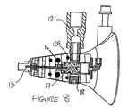
- the spool valve 15 directs flavour from the flavour inlet 12 to the needle 13, as illustrated in Figures 6-8 .
- Figure 6 shows the spool valve 15 in its retracted (or closed) position. As described above, the needle 13 and spool valve 15 are retracted upstream (cf. Figure 4 ). In this position, the orifice 12A of flavour inlet 12 is blocked by the spool valve 15 and sealed by the positioning of O-ring seals 16 either side thereof. Therefore, no flavour can escape from the flavour inlet into the spool valve 15 and nothing is delivered to the needle 13.
- Item 18 is a sealed plug which can be removed to allow the flavour inlet 12 to be connected to the opposite side of the apparatus, if desired.
- some or all of the apparatus may be provided with heating means to ensure that the flavour (which may initially be supplied in solid granular or crystalline form) is kept in a liquid state during its passage through the apparatus.
Abstract
Description
- This invention relates to the field of apparatus and methods for applying an additive to a cigarette filter and to cigarettes incorporating such filters.
- Although the present invention is described with reference to the addition of flavouring to a cigarette filter, the invention is equally relevant to the application of other additives, for example those which may affect the burn characteristics of the cigarette.
- Several methods are known of adding flavouring to cigarette filters.
GB 1342931 -
GB2229078 -
WO 02/069745 -
GB2236656 - With reference to
Figure 1 ,US2003/0224918A1 (Philip Morris USA Inc) attempts to mitigate these problems by providing a filter making apparatus in which the flavour is more precisely positioned within the tow material. There is provided a positioning device 1 with a passageway therethrough into which liquid flavourant is supplied. A continuous strand of textile material 2 is guided through the passageway so that it becomes saturated with the flavourant. A portion of the positioning device 1a then guides the continuous strand of textile material into the path offilter tow material 3. that is being converged around it, as it exits towfunnel 6 intotongue 7, to form a cigarette filter rod. - The finished filter therefore comprises compressed filter tow material surrounding an approximately centrally-placed strand of flavoured textile material. The positioning and accuracy of the dose of the flavour is thus improved, compared with the prior art methods described above.
- However, the method described in
US2003/0224918A1 suffers from several potential disadvantages: - the flavoured textile strand is visible in the finished product, which may lead the smoker to view this as a flaw;
- there is a possibility that the smoker may dislodge the strand from the filter during inhalation;
- the dose of flavour which can be applied is limited by the absorbency characteristics of the textile strand;
- it is undesirable to place anything (such as the positioning device) in the path of the forward-moving tow material because of the risk of impeding or disrupting its flow, leading to defective product.
-
US patent 4549875 describes a method for applying a smoke modifying agent into a filter tow stream at the point where the filter rod is formed by providing a fixed needle through which the smoke modifying agent is applied. This technique has the disadvantage that the needle can form an obstruction and/or a hazard to the operator when the filter making machine needs to be reset or maintained, for example in the event of tow breakage, tow pallet changeover or machine stoppage. - It is therefore an object of the present invention to provide a method and apparatus for applying a liquid additive to a filter which seeks to alleviate the above-described disadvantages.
- According to a first aspect of the invention there is provided apparatus for applying an additive to cigarette filter tow material which is in, or exiting, a filter tow funnel, the apparatus comprising:
- a flavour inlet;
- a valve; and
- a hollow needle positioned downstream of at least a portion of said filter tow funnel, the needle being in fluid communication controlled by said valve with said flavour inlet
- The use of a needle to apply the additive to the tow material enables the additive to be placed precisely within the tow, preferably as close to the centre line of the moving tow as possible. In this way, the additive is fully enclosed by the tow moving around it and the additive can be evenly and cleanly incorporated into the tow material. The risk of other apparatus in the production line being contaminated by the additive is minimised as the additive is fully enclosed within the needle or other parts of the apparatus of the invention throughout, until being delivered into the heart of the tow material.
- Contrary to the expectation that it would be undesirable to place anything in the path of the moving tow, the use of the needle does not adversely affect the flow of the tow.
- The prior art disadvantages associated with the use of a flavoured textile strand are eliminated. Retracting the needle enables operators to work on the apparatus, for example during setting-up procedures, without risk of needle stick injury. Correspondingly, the needle itself is protected from damage when in the retracted position.
- Preferably, said longitudinal axis is substantially parallel with a tapered inner surface of said tow funnel. The tapered inner surface of the tow funnel determines and guides the path of the moving tow material. Moving the needle into the tow along an axis substantially parallel with the inner surface of the tow funnel, or preferably substantially parallel to the centre line of the flow path of said tow, allows the needle to enter the tow at an angle which minimises disruption to the flow path, both upon entry of the needle and when in use with the tow flowing around the needle.
- Preferably, said needle is selectively moveable between said forward and retracted positions by said valve which is preferably pneumatically-operated. Preferably, the orifice at the distal end of the needle is in the range 0.5mn-1.0mm.
- In a preferred form, the apparatus further comprises heating means. Heating means can be used to ensure the additive remains in a liquid state during its passage through the apparatus. Preferably, said additive is provided in solid form and melted into a liquid during passage through the apparatus.
- Preferably, the delivery of additive to the flavour inlet is regulated by additive metering means. Use of the needle in combination with additive metering means enables a carefully controlled dose of additive to be supplied, taking into account the speed of the tow, the desired strength of dose, the size of the needle orifice and other factors.
- Preferably, the passage of additive from the flavour inlet to the needle is controlled by said valve.
- Ideally, said valve is provided with one or more O-ring seals.
- In a preferred embodiment, said additive is a flavour.
- According to a second aspect of the invention, there is provided a method of applying additive to a cigarette filter, comprising the steps of:
- providing apparatus as described in any of the preceding paragraphs;
- supplying an additive to said flavour inlet;
- actuating said valve so as to move said valve and said needle into the forward position, into the path of tow material which is in, or exiting a tow funnel;
- delivering additive via said needle into the tow.
- Preferably, the method further comprises the step of heating all or part of the apparatus to ensure the additive is in liquid form.
- According to a third aspect of the invention, there is provided a cigarette filter manufactured according to the method of or using apparatus as described in any of the preceding paragraphs.
- According to a fourth aspect of the invention, there is provided a cigarette incorporating a filter as claimed described in the preceding paragraph.
- Preferred embodiments of the present invention will now be more particularly described, by way of example only, with reference to the accompanying drawings in which:
-
Figure 1 (PRIOR ART) is a side elevation view of part of the apparatus ofUS2003/0224918A1 ; -
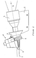
Figure 2 is a side elevation view of the apparatus embodying the first aspect of the present invention; -
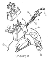
Figure 3 is an exploded view of part of the apparatus; -
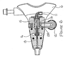
Figure 4 is a cross-sectional side view of part ofFigure 2 , with the needle in the retracted position; -
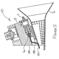
Figure 5 is a cross-sectional side view of part ofFigure 2 , with the needle in the forward position; -
Figure 6 is a cross-sectional top view of part of the spool valve assembly, shown in the retracted position; -
Figure 7 is a cross-sectional top view of part of the spool valve assembly, shown in the forward position; and -
Figure 8 is another cross-sectional view of part of the spool valve assembly, shown in the forward position, showing the flow path for the additive. - With reference to
Figure 2 , the conventional parts of the apparatus are identified as follows.Tow filter material 3 is delivered to the apparatus from an adjacent processing machine in the production line. Thetow 3 is delivered into the rear of a stuffer jet assembly 4 which is mounted at an angle on a stuffer jet assembly mounting bracket 5. - The relatively loose-
fibred tow 3 is channelled into atow funnel 6 where it is compressed and guided into a rod of narrowed diameter by the time it exits the end oftongue 7 at the downstream end of thetow funnel 6. - Additive (in this case, flavour) applicator apparatus according to the first aspect of the present invention is also illustrated in
Figure 2 . Theflavour applicator assembly 10 is mounted in the region of thetow funnel 6. - Liquid flavour is applied to the tow by means of a
hollow needle 13. As can be seen most clearly inFigures 4 and5 , the needle is not linear, but is shaped as shown. Preferably, theneedle 13 comprises three sections - aproximal section 13A which is the upstream end, anangled centre section 13B, and a distal section 13C which is the downstream end. The distal section 13C is preferably relatively short and is substantially parallel to theproximal section 13A. - The
needle 13 is moveable between two positions - a retracted position (seeFigure 4 ) wherein it is wholly retained inside theflavour applicator assembly 10, and a forward position (seeFigure 5 ) wherein at least the distal end 13C of the needle is positioned within the flow path of thetow material 3. A hydraulically or pneumatically operatedspring 14 moves the needle between the two positions on demand. - The
needle 13 is mounted to aspool valve 15. With reference toFigure 4 , in the retracted position, thespool valve 15 and hence needle 13 is biased rearwardly (upstream), by aspring 14. - Upon supply of compressed air to an air inlet 11, the
spool valve 15 andneedle 13 are pushed forwardly (downstream), against the action ofspring 14, to the forward position illustrated inFigure 5 . In this position, the distal end 13C of the needle moves through a slot (not shown) in the housing of theflavour applicator assembly 10 and protrudes into the flow path of the tow. In this position, the apparatus is ready to deliver flavour into the tow. - Flavour is supplied to the
flavour applicator assembly 10 via aflavour inlet 12 which is coupled to a universal flavour applicator (additive metering means) of known type (not illustrated), for example the UFA1000 flavour applicator manufactured by CB Kaymich & Co. Limited. The additive metering means is designed for use with many types of cold or heated flavours, such as menthol (crystal or solution), mint, fruit, clove, vanilla, liqueurs etc. - The
spool valve 15 directs flavour from theflavour inlet 12 to theneedle 13, as illustrated inFigures 6-8 .Figure 6 shows thespool valve 15 in its retracted (or closed) position. As described above, theneedle 13 andspool valve 15 are retracted upstream (cf.Figure 4 ). In this position, theorifice 12A offlavour inlet 12 is blocked by thespool valve 15 and sealed by the positioning of O-ring seals 16 either side thereof. Therefore, no flavour can escape from the flavour inlet into thespool valve 15 and nothing is delivered to theneedle 13. - Turning now to
Figures 7 and8 , when theneedle 13 andspool valve 15 are in the forward position (cf.Figure 5 ), theorifice 12A offlavour inlet 12 is now adjacent an orifice in thespool valve 15. This allows flavour to be delivered from theflavour inlet 12 via an annular undercut 17 into thespool valve 15 and then into theneedle 13. The position of the distal end 13C of the needle means that flavour is delivered right into the centre of the tow. -
Item 18 is a sealed plug which can be removed to allow theflavour inlet 12 to be connected to the opposite side of the apparatus, if desired. - In a preferred embodiment, some or all of the apparatus may be provided with heating means to ensure that the flavour (which may initially be supplied in solid granular or crystalline form) is kept in a liquid state during its passage through the apparatus.
Claims (13)
- Apparatus for applying an additive to cigarette filter tow material which is in, or exiting, a filter tow funnel, the apparatus comprising:a flavour inlet;a valve; anda hollow needle positioned downstream of at least a portion of said filter tow funnel, the needle being in fluid communication controlled by said valve with said flavour inlet,whereby, in use, an additive is delivered by said needle into the path of said filter tow material, characterised in that said needle is selectively moveable along a longitudinal axis between a forward position, in which at least the distal end of the needle is in the path of the filter tow material, and a retracted position, in which said needle is not in the path of said tow material.
- Apparatus as claimed in claim 1 wherein said longitudinal axis is substantially parallel with a tapered inner surface of said tow funnel.
- Apparatus as claimed in claim 1 wherein said longitudinal axis is substantially parallel to the centre line of the flow path of said tow.
- Apparatus as claimed in any of the preceding claims wherein said needle is selectively moveable between said forward and retracted positions by said valve which is preferably pneumatically-operated.
- Apparatus as claimed in any of the preceding claims wherein the orifice at the distal end of the needle is in the range 0.5mm-1.0mm.
- Apparatus as claimed in any of the preceding claims further comprising heating means.
- Apparatus as claimed in any of the preceding claims wherein said additive is provided in solid form and melted into a liquid during passage through the apparatus.
- Apparatus as claimed in any of the preceding claims wherein the delivery of additive to the flavour inlet is regulated by additive metering means.
- Apparatus as claimed in any of the preceding claims wherein the passage of additive from the flavour inlet to the needle is controlled by said valve.
- Apparatus as claimed in any of the preceding claims wherein said valve is provided with one or more O-ring seals.
- Apparatus as claimed in any of the preceding claims wherein said additive is a flavour.
- A method of applying additive to a cigarette filter, comprising the steps of:providing apparatus as claimed in any of the preceding claims;supplying an additive to said flavour inlet;actuating said valve so as to move said valveand said needle into the forward position, into the path of tow material which is in, or exiting a tow funnel;delivering additive via said needle into the tow.
- Method as claimed in 12 further comprising the step of heating all or part of the apparatus to ensure the additive is in liquid form.
Applications Claiming Priority (2)
| Application Number | Priority Date | Filing Date | Title |
|---|---|---|---|
| GB0417068A GB2416662A (en) | 2004-07-30 | 2004-07-30 | Apparatus for applying an additive to cigarette filter tow material |
| PCT/GB2005/002851 WO2006010895A1 (en) | 2004-07-30 | 2005-07-20 | Additive applicator |
Publications (2)
| Publication Number | Publication Date |
|---|---|
| EP1781126A1 EP1781126A1 (en) | 2007-05-09 |
| EP1781126B1 true EP1781126B1 (en) | 2008-09-10 |
Family
ID=32947753
Family Applications (1)
| Application Number | Title | Priority Date | Filing Date |
|---|---|---|---|
| EP05767864A Not-in-force EP1781126B1 (en) | 2004-07-30 | 2005-07-20 | Additive applicator |
Country Status (7)
| Country | Link |
|---|---|
| US (1) | US7770585B2 (en) |
| EP (1) | EP1781126B1 (en) |
| JP (1) | JP4907529B2 (en) |
| AT (1) | ATE407580T1 (en) |
| DE (1) | DE602005009715D1 (en) |
| GB (1) | GB2416662A (en) |
| WO (1) | WO2006010895A1 (en) |
Families Citing this family (13)
| Publication number | Priority date | Publication date | Assignee | Title |
|---|---|---|---|---|
| US7740019B2 (en) | 2006-08-02 | 2010-06-22 | R.J. Reynolds Tobacco Company, Inc. | Equipment and associated method for insertion of material into cigarette filters |
| GB0702769D0 (en) * | 2007-02-13 | 2007-03-21 | British American Tobacco Co | A Method and apparatus for the manufacture of smoking articles |
| GB0714530D0 (en) * | 2007-07-25 | 2007-09-05 | British American Tobacco Co | New apparatus and method |
| EP2110031A1 (en) | 2008-04-18 | 2009-10-21 | Philip Morris Products S.A. | Filter making apparatus |
| GB0905211D0 (en) * | 2009-03-26 | 2009-05-13 | British American Tobacco Co | Guide nozzle for use with filter rod manufacturing apparatus |
| GB0905210D0 (en) * | 2009-03-26 | 2009-05-13 | British American Tobacco Co | Rod for a smoking article and method and apparatus for manufacture |
| JP5487357B2 (en) * | 2011-02-21 | 2014-05-07 | 日本たばこ産業株式会社 | Cigarette filter manufacturing apparatus and cigarette filter manufacturing method |
| ITBO20110709A1 (en) * | 2011-12-14 | 2013-06-15 | Gd Spa | COMPACTION UNIT PROVIDED WITH A WIRE INSERTION UNIT FOR AN AUTOMATIC PACKAGING MACHINE FOR THE PRODUCTION OF FILTERS FOR CIGARETTES. |
| PL2822409T3 (en) * | 2012-03-05 | 2016-11-30 | Method and device for supplying filter material to a filter rod forming machine | |
| PL2772146T3 (en) * | 2013-02-28 | 2019-03-29 | Hauni Maschinenbau Gmbh | Device, method and apparatus for producing a filter rod in the tobacco processing industry |
| PL225859B1 (en) * | 2013-07-22 | 2017-05-31 | Int Tobacco Machinery Poland Spółka Z Ograniczoną Odpowiedzialnością | The method and element for conducting the filter fiber band and the machine for producing filter bars |
| US10492522B2 (en) | 2017-05-03 | 2019-12-03 | R.J. Reynolds Tobacco Company | Flavored menthol-containing objects for application to smoking article components |
| US11744278B2 (en) | 2021-02-12 | 2023-09-05 | R.J. Reynolds Tobacco Company | Apparatus and method for applying an additive to a tobacco rod of a smoking article |
Family Cites Families (9)
| Publication number | Priority date | Publication date | Assignee | Title |
|---|---|---|---|---|
| GB1103091A (en) * | 1963-06-27 | 1968-02-14 | Cigarette Components Ltd | Improvements in or relating to tobacco smoke filters |
| US3485208A (en) * | 1963-12-30 | 1969-12-23 | Cigarette Components Ltd | Apparatus for injecting tobacco smoke modifying material into multiple length filter rods |
| US4476807A (en) * | 1983-02-18 | 1984-10-16 | R. J. Reynolds Tobacco Company | Apparatus for application of additives to cigarette filter tow |
| US4549875A (en) | 1983-06-02 | 1985-10-29 | R. J. Reynolds Tobacco Co. | Manufacture of tobacco smoke filters |
| US4770193A (en) * | 1983-06-02 | 1988-09-13 | R. J. Reynolds Tobacco Company | Manufacture of tobacco smoke filters |
| US4768526A (en) | 1983-06-02 | 1988-09-06 | R. J. Reynolds Tobacco Company | Tobacco smoke filters |
| US5387285A (en) * | 1992-06-02 | 1995-02-07 | R. J. Reynolds Tobacco Company | Apparatus for injecting a fluid into filter tow |
| US7074170B2 (en) * | 2002-03-29 | 2006-07-11 | Philip Morris Usa Inc. | Method and apparatus for making cigarette filters with a centrally located flavored element |
| ATE346513T1 (en) * | 2002-09-11 | 2006-12-15 | Hauni Maschinenbau Ag | INJECTION OF A MEDIUM INTO FILTER SEGMENTS |
-
2004
- 2004-07-30 GB GB0417068A patent/GB2416662A/en not_active Withdrawn
-
2005
- 2005-07-20 EP EP05767864A patent/EP1781126B1/en not_active Not-in-force
- 2005-07-20 US US11/658,797 patent/US7770585B2/en not_active Expired - Fee Related
- 2005-07-20 WO PCT/GB2005/002851 patent/WO2006010895A1/en active IP Right Grant
- 2005-07-20 DE DE602005009715T patent/DE602005009715D1/en active Active
- 2005-07-20 JP JP2007523143A patent/JP4907529B2/en not_active Expired - Fee Related
- 2005-07-20 AT AT05767864T patent/ATE407580T1/en not_active IP Right Cessation
Also Published As
| Publication number | Publication date |
|---|---|
| JP2008507967A (en) | 2008-03-21 |
| GB2416662A (en) | 2006-02-08 |
| JP4907529B2 (en) | 2012-03-28 |
| ATE407580T1 (en) | 2008-09-15 |
| WO2006010895A1 (en) | 2006-02-02 |
| US20080308114A1 (en) | 2008-12-18 |
| GB0417068D0 (en) | 2004-09-01 |
| EP1781126A1 (en) | 2007-05-09 |
| US7770585B2 (en) | 2010-08-10 |
| DE602005009715D1 (en) | 2008-10-23 |
Similar Documents
| Publication | Publication Date | Title |
|---|---|---|
| EP1781126B1 (en) | Additive applicator | |
| US9770052B2 (en) | Rod for a smoking article and method and apparatus for manufacture | |
| US4476807A (en) | Apparatus for application of additives to cigarette filter tow | |
| US5387285A (en) | Apparatus for injecting a fluid into filter tow | |
| US8408215B2 (en) | Filter making apparatus | |
| US20170325496A1 (en) | Apparatus and Method for Filter Manufacture | |
| EP2178403B1 (en) | Apparatus and method for forming a rod for a smoking article | |
| US4525385A (en) | Application of additives to cigarette filter tow | |
| EP2117365B1 (en) | A method and apparatus for the manufacture of smoking articles | |
| EP2123180A1 (en) | Device for inserting additives into a previously rounded line for the manufacture of tobacco products | |
| EP3895551A1 (en) | Flavouring component for a smoking article | |
| JP2004173591A (en) | Method and apparatus for producing sheath-core-type cigarette filter |
Legal Events
| Date | Code | Title | Description |
|---|---|---|---|
| PUAI | Public reference made under article 153(3) epc to a published international application that has entered the european phase |
Free format text: ORIGINAL CODE: 0009012 |
|
| 17P | Request for examination filed |
Effective date: 20070122 |
|
| AK | Designated contracting states |
Kind code of ref document: A1 Designated state(s): AT BE BG CH CY CZ DE DK EE ES FI FR GB GR HU IE IS IT LI LT LU LV MC NL PL PT RO SE SI SK TR |
|
| DAX | Request for extension of the european patent (deleted) | ||
| GRAP | Despatch of communication of intention to grant a patent |
Free format text: ORIGINAL CODE: EPIDOSNIGR1 |
|
| GRAS | Grant fee paid |
Free format text: ORIGINAL CODE: EPIDOSNIGR3 |
|
| GRAA | (expected) grant |
Free format text: ORIGINAL CODE: 0009210 |
|
| AK | Designated contracting states |
Kind code of ref document: B1 Designated state(s): AT BE BG CH CY CZ DE DK EE ES FI FR GB GR HU IE IS IT LI LT LU LV MC NL PL PT RO SE SI SK TR |
|
| REG | Reference to a national code |
Ref country code: GB Ref legal event code: FG4D |
|
| REG | Reference to a national code |
Ref country code: CH Ref legal event code: EP |
|
| REG | Reference to a national code |
Ref country code: IE Ref legal event code: FG4D |
|
| REF | Corresponds to: |
Ref document number: 602005009715 Country of ref document: DE Date of ref document: 20081023 Kind code of ref document: P |
|
| PG25 | Lapsed in a contracting state [announced via postgrant information from national office to epo] |
Ref country code: LT Free format text: LAPSE BECAUSE OF FAILURE TO SUBMIT A TRANSLATION OF THE DESCRIPTION OR TO PAY THE FEE WITHIN THE PRESCRIBED TIME-LIMIT Effective date: 20080910 |
|
| PG25 | Lapsed in a contracting state [announced via postgrant information from national office to epo] |
Ref country code: SI Free format text: LAPSE BECAUSE OF FAILURE TO SUBMIT A TRANSLATION OF THE DESCRIPTION OR TO PAY THE FEE WITHIN THE PRESCRIBED TIME-LIMIT Effective date: 20080910 Ref country code: FI Free format text: LAPSE BECAUSE OF FAILURE TO SUBMIT A TRANSLATION OF THE DESCRIPTION OR TO PAY THE FEE WITHIN THE PRESCRIBED TIME-LIMIT Effective date: 20080910 Ref country code: LV Free format text: LAPSE BECAUSE OF FAILURE TO SUBMIT A TRANSLATION OF THE DESCRIPTION OR TO PAY THE FEE WITHIN THE PRESCRIBED TIME-LIMIT Effective date: 20080910 Ref country code: AT Free format text: LAPSE BECAUSE OF FAILURE TO SUBMIT A TRANSLATION OF THE DESCRIPTION OR TO PAY THE FEE WITHIN THE PRESCRIBED TIME-LIMIT Effective date: 20080910 |
|
| PG25 | Lapsed in a contracting state [announced via postgrant information from national office to epo] |
Ref country code: BE Free format text: LAPSE BECAUSE OF FAILURE TO SUBMIT A TRANSLATION OF THE DESCRIPTION OR TO PAY THE FEE WITHIN THE PRESCRIBED TIME-LIMIT Effective date: 20080910 |
|
| PG25 | Lapsed in a contracting state [announced via postgrant information from national office to epo] |
Ref country code: BG Free format text: LAPSE BECAUSE OF FAILURE TO SUBMIT A TRANSLATION OF THE DESCRIPTION OR TO PAY THE FEE WITHIN THE PRESCRIBED TIME-LIMIT Effective date: 20081210 Ref country code: ES Free format text: LAPSE BECAUSE OF FAILURE TO SUBMIT A TRANSLATION OF THE DESCRIPTION OR TO PAY THE FEE WITHIN THE PRESCRIBED TIME-LIMIT Effective date: 20081221 |
|
| PG25 | Lapsed in a contracting state [announced via postgrant information from national office to epo] |
Ref country code: IS Free format text: LAPSE BECAUSE OF FAILURE TO SUBMIT A TRANSLATION OF THE DESCRIPTION OR TO PAY THE FEE WITHIN THE PRESCRIBED TIME-LIMIT Effective date: 20090110 Ref country code: CZ Free format text: LAPSE BECAUSE OF FAILURE TO SUBMIT A TRANSLATION OF THE DESCRIPTION OR TO PAY THE FEE WITHIN THE PRESCRIBED TIME-LIMIT Effective date: 20080910 Ref country code: PT Free format text: LAPSE BECAUSE OF FAILURE TO SUBMIT A TRANSLATION OF THE DESCRIPTION OR TO PAY THE FEE WITHIN THE PRESCRIBED TIME-LIMIT Effective date: 20090210 Ref country code: RO Free format text: LAPSE BECAUSE OF FAILURE TO SUBMIT A TRANSLATION OF THE DESCRIPTION OR TO PAY THE FEE WITHIN THE PRESCRIBED TIME-LIMIT Effective date: 20080910 Ref country code: SK Free format text: LAPSE BECAUSE OF FAILURE TO SUBMIT A TRANSLATION OF THE DESCRIPTION OR TO PAY THE FEE WITHIN THE PRESCRIBED TIME-LIMIT Effective date: 20080910 |
|
| PLBE | No opposition filed within time limit |
Free format text: ORIGINAL CODE: 0009261 |
|
| STAA | Information on the status of an ep patent application or granted ep patent |
Free format text: STATUS: NO OPPOSITION FILED WITHIN TIME LIMIT |
|
| PG25 | Lapsed in a contracting state [announced via postgrant information from national office to epo] |
Ref country code: EE Free format text: LAPSE BECAUSE OF FAILURE TO SUBMIT A TRANSLATION OF THE DESCRIPTION OR TO PAY THE FEE WITHIN THE PRESCRIBED TIME-LIMIT Effective date: 20080910 Ref country code: DK Free format text: LAPSE BECAUSE OF FAILURE TO SUBMIT A TRANSLATION OF THE DESCRIPTION OR TO PAY THE FEE WITHIN THE PRESCRIBED TIME-LIMIT Effective date: 20080910 |
|
| 26N | No opposition filed |
Effective date: 20090611 |
|
| PG25 | Lapsed in a contracting state [announced via postgrant information from national office to epo] |
Ref country code: SE Free format text: LAPSE BECAUSE OF FAILURE TO SUBMIT A TRANSLATION OF THE DESCRIPTION OR TO PAY THE FEE WITHIN THE PRESCRIBED TIME-LIMIT Effective date: 20081210 |
|
| PG25 | Lapsed in a contracting state [announced via postgrant information from national office to epo] |
Ref country code: MC Free format text: LAPSE BECAUSE OF NON-PAYMENT OF DUE FEES Effective date: 20090731 |
|
| REG | Reference to a national code |
Ref country code: CH Ref legal event code: PL |
|
| REG | Reference to a national code |
Ref country code: FR Ref legal event code: ST Effective date: 20100331 |
|
| REG | Reference to a national code |
Ref country code: IE Ref legal event code: MM4A |
|
| PG25 | Lapsed in a contracting state [announced via postgrant information from national office to epo] |
Ref country code: LI Free format text: LAPSE BECAUSE OF NON-PAYMENT OF DUE FEES Effective date: 20090731 Ref country code: FR Free format text: LAPSE BECAUSE OF NON-PAYMENT OF DUE FEES Effective date: 20090731 Ref country code: CH Free format text: LAPSE BECAUSE OF NON-PAYMENT OF DUE FEES Effective date: 20090731 |
|
| PG25 | Lapsed in a contracting state [announced via postgrant information from national office to epo] |
Ref country code: PL Free format text: LAPSE BECAUSE OF FAILURE TO SUBMIT A TRANSLATION OF THE DESCRIPTION OR TO PAY THE FEE WITHIN THE PRESCRIBED TIME-LIMIT Effective date: 20080910 |
|
| PG25 | Lapsed in a contracting state [announced via postgrant information from national office to epo] |
Ref country code: IE Free format text: LAPSE BECAUSE OF NON-PAYMENT OF DUE FEES Effective date: 20090720 |
|
| PG25 | Lapsed in a contracting state [announced via postgrant information from national office to epo] |
Ref country code: GR Free format text: LAPSE BECAUSE OF FAILURE TO SUBMIT A TRANSLATION OF THE DESCRIPTION OR TO PAY THE FEE WITHIN THE PRESCRIBED TIME-LIMIT Effective date: 20081211 |
|
| PG25 | Lapsed in a contracting state [announced via postgrant information from national office to epo] |
Ref country code: LU Free format text: LAPSE BECAUSE OF NON-PAYMENT OF DUE FEES Effective date: 20090720 |
|
| PG25 | Lapsed in a contracting state [announced via postgrant information from national office to epo] |
Ref country code: IT Free format text: LAPSE BECAUSE OF NON-PAYMENT OF DUE FEES Effective date: 20100720 |
|
| PG25 | Lapsed in a contracting state [announced via postgrant information from national office to epo] |
Ref country code: HU Free format text: LAPSE BECAUSE OF FAILURE TO SUBMIT A TRANSLATION OF THE DESCRIPTION OR TO PAY THE FEE WITHIN THE PRESCRIBED TIME-LIMIT Effective date: 20090311 |
|
| PGRI | Patent reinstated in contracting state [announced from national office to epo] |
Ref country code: IT Effective date: 20110616 |
|
| PG25 | Lapsed in a contracting state [announced via postgrant information from national office to epo] |
Ref country code: TR Free format text: LAPSE BECAUSE OF FAILURE TO SUBMIT A TRANSLATION OF THE DESCRIPTION OR TO PAY THE FEE WITHIN THE PRESCRIBED TIME-LIMIT Effective date: 20080910 |
|
| PG25 | Lapsed in a contracting state [announced via postgrant information from national office to epo] |
Ref country code: CY Free format text: LAPSE BECAUSE OF FAILURE TO SUBMIT A TRANSLATION OF THE DESCRIPTION OR TO PAY THE FEE WITHIN THE PRESCRIBED TIME-LIMIT Effective date: 20080910 |
|
| PGFP | Annual fee paid to national office [announced via postgrant information from national office to epo] |
Ref country code: NL Payment date: 20120731 Year of fee payment: 8 |
|
| REG | Reference to a national code |
Ref country code: NL Ref legal event code: V1 Effective date: 20140201 |
|
| PG25 | Lapsed in a contracting state [announced via postgrant information from national office to epo] |
Ref country code: NL Free format text: LAPSE BECAUSE OF NON-PAYMENT OF DUE FEES Effective date: 20140201 |
|
| PGFP | Annual fee paid to national office [announced via postgrant information from national office to epo] |
Ref country code: IT Payment date: 20140127 Year of fee payment: 9 |
|
| PGFP | Annual fee paid to national office [announced via postgrant information from national office to epo] |
Ref country code: GB Payment date: 20140710 Year of fee payment: 10 |
|
| PG25 | Lapsed in a contracting state [announced via postgrant information from national office to epo] |
Ref country code: IT Free format text: LAPSE BECAUSE OF NON-PAYMENT OF DUE FEES Effective date: 20140720 |
|
| GBPC | Gb: european patent ceased through non-payment of renewal fee |
Effective date: 20150720 |
|
| PG25 | Lapsed in a contracting state [announced via postgrant information from national office to epo] |
Ref country code: GB Free format text: LAPSE BECAUSE OF NON-PAYMENT OF DUE FEES Effective date: 20150720 |
|
| PGFP | Annual fee paid to national office [announced via postgrant information from national office to epo] |
Ref country code: DE Payment date: 20170706 Year of fee payment: 13 |
|
| REG | Reference to a national code |
Ref country code: DE Ref legal event code: R119 Ref document number: 602005009715 Country of ref document: DE |
|
| PG25 | Lapsed in a contracting state [announced via postgrant information from national office to epo] |
Ref country code: DE Free format text: LAPSE BECAUSE OF NON-PAYMENT OF DUE FEES Effective date: 20190201 |