EP1780697A2 - Plasma display apparatus equipped with ambient light sensor or motion detector - Google Patents
Plasma display apparatus equipped with ambient light sensor or motion detector Download PDFInfo
- Publication number
- EP1780697A2 EP1780697A2 EP06255587A EP06255587A EP1780697A2 EP 1780697 A2 EP1780697 A2 EP 1780697A2 EP 06255587 A EP06255587 A EP 06255587A EP 06255587 A EP06255587 A EP 06255587A EP 1780697 A2 EP1780697 A2 EP 1780697A2
- Authority
- EP
- European Patent Office
- Prior art keywords
- plasma display
- display panel
- display apparatus
- subject
- mode
- Prior art date
- Legal status (The legal status is an assumption and is not a legal conclusion. Google has not performed a legal analysis and makes no representation as to the accuracy of the status listed.)
- Withdrawn
Links
Images




Classifications
-
- G—PHYSICS
- G09—EDUCATION; CRYPTOGRAPHY; DISPLAY; ADVERTISING; SEALS
- G09G—ARRANGEMENTS OR CIRCUITS FOR CONTROL OF INDICATING DEVICES USING STATIC MEANS TO PRESENT VARIABLE INFORMATION
- G09G3/00—Control arrangements or circuits, of interest only in connection with visual indicators other than cathode-ray tubes
- G09G3/20—Control arrangements or circuits, of interest only in connection with visual indicators other than cathode-ray tubes for presentation of an assembly of a number of characters, e.g. a page, by composing the assembly by combination of individual elements arranged in a matrix no fixed position being assigned to or needed to be assigned to the individual characters or partial characters
- G09G3/22—Control arrangements or circuits, of interest only in connection with visual indicators other than cathode-ray tubes for presentation of an assembly of a number of characters, e.g. a page, by composing the assembly by combination of individual elements arranged in a matrix no fixed position being assigned to or needed to be assigned to the individual characters or partial characters using controlled light sources
- G09G3/28—Control arrangements or circuits, of interest only in connection with visual indicators other than cathode-ray tubes for presentation of an assembly of a number of characters, e.g. a page, by composing the assembly by combination of individual elements arranged in a matrix no fixed position being assigned to or needed to be assigned to the individual characters or partial characters using controlled light sources using luminous gas-discharge panels, e.g. plasma panels
- G09G3/288—Control arrangements or circuits, of interest only in connection with visual indicators other than cathode-ray tubes for presentation of an assembly of a number of characters, e.g. a page, by composing the assembly by combination of individual elements arranged in a matrix no fixed position being assigned to or needed to be assigned to the individual characters or partial characters using controlled light sources using luminous gas-discharge panels, e.g. plasma panels using AC panels
- G09G3/296—Driving circuits for producing the waveforms applied to the driving electrodes
-
- G—PHYSICS
- G09—EDUCATION; CRYPTOGRAPHY; DISPLAY; ADVERTISING; SEALS
- G09G—ARRANGEMENTS OR CIRCUITS FOR CONTROL OF INDICATING DEVICES USING STATIC MEANS TO PRESENT VARIABLE INFORMATION
- G09G3/00—Control arrangements or circuits, of interest only in connection with visual indicators other than cathode-ray tubes
- G09G3/20—Control arrangements or circuits, of interest only in connection with visual indicators other than cathode-ray tubes for presentation of an assembly of a number of characters, e.g. a page, by composing the assembly by combination of individual elements arranged in a matrix no fixed position being assigned to or needed to be assigned to the individual characters or partial characters
- G09G3/22—Control arrangements or circuits, of interest only in connection with visual indicators other than cathode-ray tubes for presentation of an assembly of a number of characters, e.g. a page, by composing the assembly by combination of individual elements arranged in a matrix no fixed position being assigned to or needed to be assigned to the individual characters or partial characters using controlled light sources
- G09G3/28—Control arrangements or circuits, of interest only in connection with visual indicators other than cathode-ray tubes for presentation of an assembly of a number of characters, e.g. a page, by composing the assembly by combination of individual elements arranged in a matrix no fixed position being assigned to or needed to be assigned to the individual characters or partial characters using controlled light sources using luminous gas-discharge panels, e.g. plasma panels
- G09G3/288—Control arrangements or circuits, of interest only in connection with visual indicators other than cathode-ray tubes for presentation of an assembly of a number of characters, e.g. a page, by composing the assembly by combination of individual elements arranged in a matrix no fixed position being assigned to or needed to be assigned to the individual characters or partial characters using controlled light sources using luminous gas-discharge panels, e.g. plasma panels using AC panels
- G09G3/291—Control arrangements or circuits, of interest only in connection with visual indicators other than cathode-ray tubes for presentation of an assembly of a number of characters, e.g. a page, by composing the assembly by combination of individual elements arranged in a matrix no fixed position being assigned to or needed to be assigned to the individual characters or partial characters using controlled light sources using luminous gas-discharge panels, e.g. plasma panels using AC panels controlling the gas discharge to control a cell condition, e.g. by means of specific pulse shapes
- G09G3/292—Control arrangements or circuits, of interest only in connection with visual indicators other than cathode-ray tubes for presentation of an assembly of a number of characters, e.g. a page, by composing the assembly by combination of individual elements arranged in a matrix no fixed position being assigned to or needed to be assigned to the individual characters or partial characters using controlled light sources using luminous gas-discharge panels, e.g. plasma panels using AC panels controlling the gas discharge to control a cell condition, e.g. by means of specific pulse shapes for reset discharge, priming discharge or erase discharge occurring in a phase other than addressing
- G09G3/2927—Details of initialising
-
- G—PHYSICS
- G09—EDUCATION; CRYPTOGRAPHY; DISPLAY; ADVERTISING; SEALS
- G09G—ARRANGEMENTS OR CIRCUITS FOR CONTROL OF INDICATING DEVICES USING STATIC MEANS TO PRESENT VARIABLE INFORMATION
- G09G3/00—Control arrangements or circuits, of interest only in connection with visual indicators other than cathode-ray tubes
- G09G3/20—Control arrangements or circuits, of interest only in connection with visual indicators other than cathode-ray tubes for presentation of an assembly of a number of characters, e.g. a page, by composing the assembly by combination of individual elements arranged in a matrix no fixed position being assigned to or needed to be assigned to the individual characters or partial characters
- G09G3/22—Control arrangements or circuits, of interest only in connection with visual indicators other than cathode-ray tubes for presentation of an assembly of a number of characters, e.g. a page, by composing the assembly by combination of individual elements arranged in a matrix no fixed position being assigned to or needed to be assigned to the individual characters or partial characters using controlled light sources
- G09G3/28—Control arrangements or circuits, of interest only in connection with visual indicators other than cathode-ray tubes for presentation of an assembly of a number of characters, e.g. a page, by composing the assembly by combination of individual elements arranged in a matrix no fixed position being assigned to or needed to be assigned to the individual characters or partial characters using controlled light sources using luminous gas-discharge panels, e.g. plasma panels
- G09G3/288—Control arrangements or circuits, of interest only in connection with visual indicators other than cathode-ray tubes for presentation of an assembly of a number of characters, e.g. a page, by composing the assembly by combination of individual elements arranged in a matrix no fixed position being assigned to or needed to be assigned to the individual characters or partial characters using controlled light sources using luminous gas-discharge panels, e.g. plasma panels using AC panels
- G09G3/291—Control arrangements or circuits, of interest only in connection with visual indicators other than cathode-ray tubes for presentation of an assembly of a number of characters, e.g. a page, by composing the assembly by combination of individual elements arranged in a matrix no fixed position being assigned to or needed to be assigned to the individual characters or partial characters using controlled light sources using luminous gas-discharge panels, e.g. plasma panels using AC panels controlling the gas discharge to control a cell condition, e.g. by means of specific pulse shapes
- G09G3/294—Control arrangements or circuits, of interest only in connection with visual indicators other than cathode-ray tubes for presentation of an assembly of a number of characters, e.g. a page, by composing the assembly by combination of individual elements arranged in a matrix no fixed position being assigned to or needed to be assigned to the individual characters or partial characters using controlled light sources using luminous gas-discharge panels, e.g. plasma panels using AC panels controlling the gas discharge to control a cell condition, e.g. by means of specific pulse shapes for lighting or sustain discharge
- G09G3/2944—Control arrangements or circuits, of interest only in connection with visual indicators other than cathode-ray tubes for presentation of an assembly of a number of characters, e.g. a page, by composing the assembly by combination of individual elements arranged in a matrix no fixed position being assigned to or needed to be assigned to the individual characters or partial characters using controlled light sources using luminous gas-discharge panels, e.g. plasma panels using AC panels controlling the gas discharge to control a cell condition, e.g. by means of specific pulse shapes for lighting or sustain discharge by varying the frequency of sustain pulses or the number of sustain pulses proportionally in each subfield of the whole frame
-
- G—PHYSICS
- G09—EDUCATION; CRYPTOGRAPHY; DISPLAY; ADVERTISING; SEALS
- G09G—ARRANGEMENTS OR CIRCUITS FOR CONTROL OF INDICATING DEVICES USING STATIC MEANS TO PRESENT VARIABLE INFORMATION
- G09G3/00—Control arrangements or circuits, of interest only in connection with visual indicators other than cathode-ray tubes
- G09G3/20—Control arrangements or circuits, of interest only in connection with visual indicators other than cathode-ray tubes for presentation of an assembly of a number of characters, e.g. a page, by composing the assembly by combination of individual elements arranged in a matrix no fixed position being assigned to or needed to be assigned to the individual characters or partial characters
- G09G3/22—Control arrangements or circuits, of interest only in connection with visual indicators other than cathode-ray tubes for presentation of an assembly of a number of characters, e.g. a page, by composing the assembly by combination of individual elements arranged in a matrix no fixed position being assigned to or needed to be assigned to the individual characters or partial characters using controlled light sources
- G09G3/28—Control arrangements or circuits, of interest only in connection with visual indicators other than cathode-ray tubes for presentation of an assembly of a number of characters, e.g. a page, by composing the assembly by combination of individual elements arranged in a matrix no fixed position being assigned to or needed to be assigned to the individual characters or partial characters using controlled light sources using luminous gas-discharge panels, e.g. plasma panels
- G09G3/288—Control arrangements or circuits, of interest only in connection with visual indicators other than cathode-ray tubes for presentation of an assembly of a number of characters, e.g. a page, by composing the assembly by combination of individual elements arranged in a matrix no fixed position being assigned to or needed to be assigned to the individual characters or partial characters using controlled light sources using luminous gas-discharge panels, e.g. plasma panels using AC panels
- G09G3/291—Control arrangements or circuits, of interest only in connection with visual indicators other than cathode-ray tubes for presentation of an assembly of a number of characters, e.g. a page, by composing the assembly by combination of individual elements arranged in a matrix no fixed position being assigned to or needed to be assigned to the individual characters or partial characters using controlled light sources using luminous gas-discharge panels, e.g. plasma panels using AC panels controlling the gas discharge to control a cell condition, e.g. by means of specific pulse shapes
- G09G3/294—Control arrangements or circuits, of interest only in connection with visual indicators other than cathode-ray tubes for presentation of an assembly of a number of characters, e.g. a page, by composing the assembly by combination of individual elements arranged in a matrix no fixed position being assigned to or needed to be assigned to the individual characters or partial characters using controlled light sources using luminous gas-discharge panels, e.g. plasma panels using AC panels controlling the gas discharge to control a cell condition, e.g. by means of specific pulse shapes for lighting or sustain discharge
- G09G3/2946—Control arrangements or circuits, of interest only in connection with visual indicators other than cathode-ray tubes for presentation of an assembly of a number of characters, e.g. a page, by composing the assembly by combination of individual elements arranged in a matrix no fixed position being assigned to or needed to be assigned to the individual characters or partial characters using controlled light sources using luminous gas-discharge panels, e.g. plasma panels using AC panels controlling the gas discharge to control a cell condition, e.g. by means of specific pulse shapes for lighting or sustain discharge by introducing variations of the frequency of sustain pulses within a frame or non-proportional variations of the number of sustain pulses in each subfield
-
- G—PHYSICS
- G09—EDUCATION; CRYPTOGRAPHY; DISPLAY; ADVERTISING; SEALS
- G09G—ARRANGEMENTS OR CIRCUITS FOR CONTROL OF INDICATING DEVICES USING STATIC MEANS TO PRESENT VARIABLE INFORMATION
- G09G2310/00—Command of the display device
- G09G2310/06—Details of flat display driving waveforms
- G09G2310/066—Waveforms comprising a gently increasing or decreasing portion, e.g. ramp
-
- G—PHYSICS
- G09—EDUCATION; CRYPTOGRAPHY; DISPLAY; ADVERTISING; SEALS
- G09G—ARRANGEMENTS OR CIRCUITS FOR CONTROL OF INDICATING DEVICES USING STATIC MEANS TO PRESENT VARIABLE INFORMATION
- G09G2320/00—Control of display operating conditions
- G09G2320/06—Adjustment of display parameters
- G09G2320/0626—Adjustment of display parameters for control of overall brightness
-
- G—PHYSICS
- G09—EDUCATION; CRYPTOGRAPHY; DISPLAY; ADVERTISING; SEALS
- G09G—ARRANGEMENTS OR CIRCUITS FOR CONTROL OF INDICATING DEVICES USING STATIC MEANS TO PRESENT VARIABLE INFORMATION
- G09G2320/00—Control of display operating conditions
- G09G2320/06—Adjustment of display parameters
- G09G2320/066—Adjustment of display parameters for control of contrast
-
- G—PHYSICS
- G09—EDUCATION; CRYPTOGRAPHY; DISPLAY; ADVERTISING; SEALS
- G09G—ARRANGEMENTS OR CIRCUITS FOR CONTROL OF INDICATING DEVICES USING STATIC MEANS TO PRESENT VARIABLE INFORMATION
- G09G2330/00—Aspects of power supply; Aspects of display protection and defect management
- G09G2330/02—Details of power systems and of start or stop of display operation
- G09G2330/021—Power management, e.g. power saving
-
- G—PHYSICS
- G09—EDUCATION; CRYPTOGRAPHY; DISPLAY; ADVERTISING; SEALS
- G09G—ARRANGEMENTS OR CIRCUITS FOR CONTROL OF INDICATING DEVICES USING STATIC MEANS TO PRESENT VARIABLE INFORMATION
- G09G2330/00—Aspects of power supply; Aspects of display protection and defect management
- G09G2330/02—Details of power systems and of start or stop of display operation
- G09G2330/021—Power management, e.g. power saving
- G09G2330/022—Power management, e.g. power saving in absence of operation, e.g. no data being entered during a predetermined time
-
- G—PHYSICS
- G09—EDUCATION; CRYPTOGRAPHY; DISPLAY; ADVERTISING; SEALS
- G09G—ARRANGEMENTS OR CIRCUITS FOR CONTROL OF INDICATING DEVICES USING STATIC MEANS TO PRESENT VARIABLE INFORMATION
- G09G2360/00—Aspects of the architecture of display systems
- G09G2360/14—Detecting light within display terminals, e.g. using a single or a plurality of photosensors
- G09G2360/144—Detecting light within display terminals, e.g. using a single or a plurality of photosensors the light being ambient light
Definitions
- This invention relates to a plasma display apparatus.
- a plasma display panel includes barrier ribs formed between a front substrate and a rear substrate. Together, the barrier ribs and the front and rear substrates form cells. Each of the cells is filled with a primary discharge gas such as neon (Ne), helium (He) or a mixed gas comprising Ne and He. In addition, each cell contains an inert gas comprising a small amount of xenon.
- a primary discharge gas such as neon (Ne), helium (He) or a mixed gas comprising Ne and He.
- He helium
- each cell contains an inert gas comprising a small amount of xenon.
- the inert gas is discharged using a high frequency voltage, ultraviolet radiation is generated.
- the ultraviolet radiation which is invisible to the human eye, excite light-emitting phosphors in each cell, thus creating a visible image.
- Plasma display panels can be made thin and slim, and thus have been in the spotlight as the next-generation of display devices.
- Embodiments of the present invention can provide a plasma display apparatus that can improve a characteristic of contrast when a plasma display panel is driven.
- Embodiments of the present invention can provide a plasma display apparatus that can decrease power consumption when a plasma display panel is driven.
- One aspect of the invention provides a plasma display apparatus containing a sensor arranged to detect the ambient illumination of a plasma display panel and a controller arranged to control at least one of a voltage of driving signal and the number of driving signals for driving the plasma display panel in accordance with the ambient illumination.
- At least one of the voltage of driving signal and the number of driving signals, when the ambient illumination is equal to or greater than a reference illumination, may be greater than at least one of the voltage of driving signal and the number of driving signals when the ambient illumination equals an average ambient illumination.
- At least one of the voltage of driving signal and the number of driving signals when the ambient illumination is less than a reference illumination may be less than at least one of the voltage of driving signal and the number of driving signals when the ambient illumination equals an average ambient illumination.
- the driving signal may be a reset signal applied to an electrode of the plasma display panel during a reset period.
- the driving signal may be a sustain signal applied to an electrode of the plasma display panel during a sustain period.
- At least one of the voltage of driving signal and the number of driving signal may be controlled in at least one of a plurality of subfields.
- Another aspect of the invention provides a plasma display apparatus containing a detector arranged to detect movement of a subject in the vicinity of a plasma display panel and a controller arranged to set an image mode into a suspend mode so that an image is not displayed on the plasma display panel, when the subject does not move during the duration of a first reference time.
- Embodiments may include one or more of the following features. Movement of a subject may be the difference between a first gray value of the subject and a second gray value of the subject in the same position of the vicinity of the plasma display panel, or a vector amount of movement of the subject.
- the controller may be arranged to convert an image mode into a standby mode, when the subject does not move during the duration of a second reference time.
- the suspend mode may be a mode in which a data signal is not applied to an electrode of the plasma display panel during an address period.
- the suspend mode may be a mode in which a sustain signal is not applied to an electrode of the plasma display panel during a sustain period.
- the detector may include a camera for taking a photograph of the subject.
- the camera may include an image memory for storing an image of the subject.
- the detector may be formed on a non-display area of the plasma display panel. There may be a plurality of detectors.
- Still another aspect of the invention provides a plasma display apparatus containing a detector arranged to detect movement of a subject in the vicinity of a plasma display panel and a controller arranged to convert an image mode into a standby mode so that an image is not displayed on the plasma display panel, when the subject does not move during the duration of a first reference time.
- Embodiments may include one or more of the following features.
- a standby mode may be a mode in which an image is displayed when the subject moves.
- the standby mode may be a mode in which a data signal is not applied to an electrode of the plasma display panel during an address period.
- FIG. 1 is a conceptual view illustrating the structure of a plasma display apparatus
- FIG. 2 shows the configuration of a plasma display panel
- FIG. 3 shows waveforms that can be used in a method of driving the plasma display panel of FIG. 1;
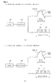
- FIG. 4 shows an arrangement for use in a method driving the plasma display apparatus in accordance with the ambient illumination of the plasma display panel
- FIG. 5 shows an arrangement where sensors are formed in a plasma display apparatus
- FIG. 6 is a block diagram schematically illustrating the configuration of a plasma display apparatus according to an embodiment of the invention.
- FIG. 7 shows an arrangement for use in a method of driving the plasma display apparatus according to movement of subject in the vicinity of a plasma display panel.
- a plasma display apparatus includes a plasma display panel PDP which can display an image thereon, a plurality of drivers including a data driver 20, a scan driver 21 and a sustain driver 23 which respectively apply driving signals to respective pluralities of electrodes of the plasma display panel, a sensor 300 which detects the ambient illumination in the vicinity of the plasma display panel, and a controller 200 which controls the plurality of drivers 20, 21, 23 to control the brightness of the image displayed on the plasma display panel in accordance with a signal of the ambient illumination provided from the sensor 300.
- a plasma display panel PDP which can display an image thereon
- a plurality of drivers including a data driver 20, a scan driver 21 and a sustain driver 23 which respectively apply driving signals to respective pluralities of electrodes of the plasma display panel, a sensor 300 which detects the ambient illumination in the vicinity of the plasma display panel, and a controller 200 which controls the plurality of drivers 20, 21, 23 to control the brightness of the image displayed on the plasma display panel in accordance with a signal of the ambient illumination provided from the sensor 300.
- the plasma display panel includes a front substrate 100 that serves as the display surface on which the images are displayed, and a rear substrate 110 forming a rear surface.
- the front substrate 100 and the rear substrate 110 are parallel to each other, and spaced apart by a predetermined distance.
- the front substrate 100 includes a scan electrode 101 (Y electrode) and a sustain electrode 102 (Z electrode), both of which are employed in controlling the discharge and light emission of the discharge cell shown in Fig. 2.
- the Y electrode 101 and the Z electrode 102 each have a transparent electrode "a” made of a transparent ITO material, and a bus electrode “b” made of a metal material.
- the Y electrode 101 and the Z electrode 102 together form an electrode pair.
- the Y electrode 101 and the Z electrode 102 are covered by at least one dielectric layer 103 for limiting the discharge current and for providing insulation.
- a protection layer 104 having magnesium oxide (MgO) deposited thereon to facilitate the discharge condition, is formed on the dielectric layer 103.
- barrier ribs 111 in the form of a stripe pattern (or well type), for forming a plurality of discharge spaces, i.e., discharge cells, are arranged in a parallel manner. Further, a plurality of address electrodes 112 (X electrodes) for use in achieving an address discharge which, in turn, results in the generation of ultraviolet light, is disposed parallel to the barrier ribs 111. Red (R), green (G) and blue (B) phosphors 113, for emitting visible light for image display upon address discharge, are coated on a top surface of the rear substrate 110. A white dielectric layer 114, which protects the address electrodes 112 and reflects the visible light emitted from the phosphors 113 to the front substrate 100, is formed generally between the address electrodes 112 and the phosphors 113.
- the plasma display panel is driven by applying a driving signal to a plurality of electrodes of the plasma display panel such as the scan electrode 101, the sustain electrode 102 and the data electrode 112 as shown in FIG. 3.
- the waveforms associated with the X, Y and Z electrodes are divided into a reset period for initializing all cells, an address period for selecting cells that are to be discharged, a sustain period for maintaining the discharging of selected cells, and an erase period for erasing wall charges within each of the discharge cells.
- a ramp-up waveform (Ramp-up) is applied to all of the Y electrodes at the same time.
- a weak dark discharge is generated in all of the discharge cells for the entire screen.
- the set-up discharge causes wall charges of a positive polarity to be accumulated at the X electrodes and the Z electrodes, and wall charges of a negative polarity to accumulate at the Y electrodes, where the Z electrodes refer to the sustain electrodes.
- a ramp-down waveform (Ramp-down) is applied, which falls from a positive polarity voltage lower than the peak voltage of the ramp-up waveform, to a given voltage lower than ground GND level voltage.
- the ramp-down waveform causes a weak erase discharge to occur in all of the cells. Therefore, excessive wall charges formed on the Y electrodes are sufficiently erased.
- the set-down discharge also optimizes the wall charges for the address period, such than an address discharge can be generated stably within the appropriate cells.
- a negative scan signal (Scan) is sequentially applied to the Y electrodes
- a positive data signal is applied to the X electrodes in synchronism with the scan signal.
- an address discharge is generated within those discharge cells to which a data signal is applied.
- wall charges sufficient for generating a discharge when a sustain voltage Vs is applied, are formed within cells selected by the address discharge.
- a positive polarity voltage Vz is applied to the Z electrodes so that erroneous discharge does not occur with the Y electrode by reducing the voltage difference between the Z electrode and the Y electrode during the set-down period and the address period.
- a sustain signal (Sus) is alternately applied to the Y electrodes and the Z electrodes.
- a sustain discharge i.e., a display discharge, is generated between the Y electrodes and the Z electrodes whenever the sustain signal is applied.
- the senor 300 detects the ambient illumination of the plasma display panel and compares the detected ambient illumination level with a reference illumination level, and the controller 200 controls the voltage of the driving signal applied to an electrode of the plasma display panel, or controls the number of driving signals applied to the electrode of the plasma display panel in accordance with the detected ambient illumination level of the plasma display panel provided from the sensor 300.
- the driving signal is the whole of driving signal which is applied to the electrodes of the plasma display panel to generate a discharge in the discharge cells during each period such as the reset period, the address period, and the sustain period, when the plasma display panel is driven.
- this is not essential to the invention in its broadest aspect.
- the driving signal is the reset signal applied to the scan electrode during the reset period or the sustain signal applied alternately to the scan electrode or the sustain electrode during the sustain period.
- the controller 200 controls the maximum voltage of reset signal to be greater than the fixed maximum voltage of reset signal applied to the scan electrode Y when the detected ambient illumination level equals an average ambient illumination level. That is, as shown in phantom, the maximum voltage of the reset signal increases from the set-up voltage (Vsetup) to the set-up voltage added a predetermined voltage ( ⁇ V).
- the average ambient illumination level is a value that is obtained by taking the average of the detected illumination levels in the vicinity of the plasma display panel when the plasma display panel has been driven for the duration of a predetermined time.
- the reset signal which is applied to the scan electrode Y has the ramp-up waveform (Ramp-up) and the ramp-down waveform (Ramp-down)
- the controller 200 controls the number of sustain signals to be greater than the fixed number of sustain signals applied to the scan electrode Y or the sustain electrode Z when the detected ambient illumination level equals the average ambient illumination level, as shown in phantom.
- the controller 200 controls the maximum voltage of reset signal to be less than the fixed maximum voltage of reset signal applied to the scan electrode Y when the detected ambient illumination level equals an average ambient illumination level. That is, as shown in phantom, the maximum voltage of the reset signal decreases from the set-up voltage (Vsetup) to the set-up voltage less a predetermined voltage ( ⁇ V).
- the controller 200 controls the number of sustain signals to be fewer than the fixed number of sustain signals applied to the scan electrode Y or the sustain electrode Z when the detecting ambient illumination level equals the average ambient illumination level, as shown in phantom.
- At least one of the maximum voltage of the reset signal and the number of sustain signals is controlled in the whole of subfields within a frame.
- it may be controlled in at least one subfield of the whole of subfields within a frame when the plasma display panel is driven.
- the whole area of the plasma display apparatus is divided into a display area 330 on which an image is displayed and a non-display area 320 on which the image is not displayed.
- the sensor 300 is positioned in the non-display area 320 of the plasma display apparatus. In this embodiment, the sensor 300 is positioned on a portion of the corner of the non-display area 320. however, this is not essential to the invention in its broadest aspect.
- non-display area 320 may be a portion of a case, which covers the plasma display panel, to protect the plasma display panel from an outer shock.
- the number of sensors may be single or plural and may be positioned at a plurality of locations.
- the plasma display apparatus can improve the contrast characteristic by controlling the voltage of the driving signal or the number of driving signals in accordance with the ambient illumination of the plasma display panel.
- the plasma display apparatus includes a plasma display panel PDP which has an image displayed thereon, a detector 400 which detects a movement of a subject in the vicinity of the plasma display panel, and a controller 500 which controls the image displayed on the plasma display panel in accordance with the movement of the subject.
- the structure of the plasma display panel is the same as the structure of the plasma display panel described in the first embodiment, a description thereof will be omitted.
- the method of driving the plasma display panel is the same as the method of driving the plasma display panel described in the first embodiment, a description thereof will be omitted.
- the detector 400 is likewise positioned in the non-display area of plasma display apparatus. It is preferably, but not essentially, positioned in a portion of one or more corners of the non-display area.
- the detector 400 may include a camera for taking a photograph of the subject. A plurality of cameras may be provided.
- the or each of the cameras may include an image memory 410 to store an image of the subject.
- the area covered by the or each camera may be controlled by operating a remote controller (not shown), that is, the remote controller controls the detecting area of the each camera so that each of cameras can take a photograph of the subject in various directions relative to the subject.
- a detector 400 detects the movement of a subject in the vicinity of the plasma display panel and provides a detecting signal of the subject to the controller 200.
- the controller 200 controls an image displayed on the plasma display panel to be converted to a predetermined mode in accordance with the detecting signal from the detector 400.
- the detector 400 detects whether the subject moves or not and checks the duration of time of the movement of the subject when the subject moves.
- the controller 500 controls the image screen of the plasma display panel to be converted to an image mode 530 when the subject moves, and controls the image screen of the plasma display panel to be converted to suspend mode 510 when the subject does not move during the duration of a first reference time.
- the suspend mode 510 is a mode in which no visible image is displayed on the plasma display panel.
- the plasma display apparatus In suspend mode, although the plasma display apparatus processes image data (i.e., R, G, B, and Y, U, V), the plasma display apparatus does not have a data signal or a sustain signal applied to the electrodes of the plasma display panel.
- image data i.e., R, G, B, and Y, U, V
- the suspend mode 510 is changed to a standby mode 520 when the subject does not move during the duration of a second reference time greater than the duration of a first reference time.
- the standby mode 520 is a mode in which a minimum voltage needs to be applied to the plasma display apparatus in order to display an image on the plasma display panel when the subject moves.
- the standby mode 520 is a mode which at least one signal of the data signal and the sustain signal is also not applied to the electrodes of the plasma display panel.
- the detector 400 may for example define the movement of the subject by using a gray value of the subject or a vector value of the subject.
- the movement of the subject may be defined by the difference between a first gray value of the subject and a second gray value of the subject.
- the first gray value is the detected gray value of the subject at a first time in a given position in the vicinity of the plasma display panel and the second gray value is the detected gray value of the subject at a second time after the first time in the same position in the vicinity of the plasma display panel.
- the vector value of the subject is a direction value and a magnitude value of the movement of the subject in the given position in the vicinity of the plasma display panel.
- the plasma display apparatus can decrease power consumption by putting the image screen into the image mode or the suspend mode in accordance with the movement of a subject in the vicinity of the plasma display panel and displays an image which is a picture taken of the subject on the plasma display panel.
Landscapes
- Engineering & Computer Science (AREA)
- Physics & Mathematics (AREA)
- Power Engineering (AREA)
- Plasma & Fusion (AREA)
- Computer Hardware Design (AREA)
- General Physics & Mathematics (AREA)
- Theoretical Computer Science (AREA)
- Control Of Indicators Other Than Cathode Ray Tubes (AREA)
- Transforming Electric Information Into Light Information (AREA)
- Controls And Circuits For Display Device (AREA)
- Control Of Gas Discharge Display Tubes (AREA)
Abstract
Description
- This invention relates to a plasma display apparatus.
- A plasma display panel includes barrier ribs formed between a front substrate and a rear substrate. Together, the barrier ribs and the front and rear substrates form cells. Each of the cells is filled with a primary discharge gas such as neon (Ne), helium (He) or a mixed gas comprising Ne and He. In addition, each cell contains an inert gas comprising a small amount of xenon.
- If the inert gas is discharged using a high frequency voltage, ultraviolet radiation is generated. The ultraviolet radiation, which is invisible to the human eye, excite light-emitting phosphors in each cell, thus creating a visible image. Plasma display panels can be made thin and slim, and thus have been in the spotlight as the next-generation of display devices.
- Embodiments of the present invention can provide a plasma display apparatus that can improve a characteristic of contrast when a plasma display panel is driven.
- Embodiments of the present invention can provide a plasma display apparatus that can decrease power consumption when a plasma display panel is driven.
- One aspect of the invention provides a plasma display apparatus containing a sensor arranged to detect the ambient illumination of a plasma display panel and a controller arranged to control at least one of a voltage of driving signal and the number of driving signals for driving the plasma display panel in accordance with the ambient illumination.
- One or more of the following features may be provided. At least one of the voltage of driving signal and the number of driving signals, when the ambient illumination is equal to or greater than a reference illumination, may be greater than at least one of the voltage of driving signal and the number of driving signals when the ambient illumination equals an average ambient illumination.
- At least one of the voltage of driving signal and the number of driving signals when the ambient illumination is less than a reference illumination, may be less than at least one of the voltage of driving signal and the number of driving signals when the ambient illumination equals an average ambient illumination.
- The driving signal may be a reset signal applied to an electrode of the plasma display panel during a reset period.
- The driving signal may be a sustain signal applied to an electrode of the plasma display panel during a sustain period.
- At least one of the voltage of driving signal and the number of driving signal may be controlled in at least one of a plurality of subfields.
- Another aspect of the invention provides a plasma display apparatus containing a detector arranged to detect movement of a subject in the vicinity of a plasma display panel and a controller arranged to set an image mode into a suspend mode so that an image is not displayed on the plasma display panel, when the subject does not move during the duration of a first reference time.
- Embodiments may include one or more of the following features. Movement of a subject may be the difference between a first gray value of the subject and a second gray value of the subject in the same position of the vicinity of the plasma display panel, or a vector amount of movement of the subject.
- The controller may be arranged to convert an image mode into a standby mode, when the subject does not move during the duration of a second reference time.
- The suspend mode may be a mode in which a data signal is not applied to an electrode of the plasma display panel during an address period.
- The suspend mode may be a mode in which a sustain signal is not applied to an electrode of the plasma display panel during a sustain period.
- The detector may include a camera for taking a photograph of the subject.
- The camera may include an image memory for storing an image of the subject.
- The detector may be formed on a non-display area of the plasma display panel. There may be a plurality of detectors.
- Still another aspect of the invention provides a plasma display apparatus containing a detector arranged to detect movement of a subject in the vicinity of a plasma display panel and a controller arranged to convert an image mode into a standby mode so that an image is not displayed on the plasma display panel, when the subject does not move during the duration of a first reference time.
- Embodiments may include one or more of the following features. A standby mode may be a mode in which an image is displayed when the subject moves.
- The standby mode may be a mode in which a data signal is not applied to an electrode of the plasma display panel during an address period.
- It is to be understood that both the foregoing general description and the following detailed description are exemplary and explanatory only, and are intended to provide further explanation of the invention as claimed.
- Embodiments of the invention will be described in detail by way of non-limiting example only, with reference to the drawings, in which like numerals refer to like elements, in which
- FIG. 1 is a conceptual view illustrating the structure of a plasma display apparatus;
- FIG. 2 shows the configuration of a plasma display panel;
- FIG. 3 shows waveforms that can be used in a method of driving the plasma display panel of FIG. 1;
- FIG. 4 shows an arrangement for use in a method driving the plasma display apparatus in accordance with the ambient illumination of the plasma display panel;
- FIG. 5 shows an arrangement where sensors are formed in a plasma display apparatus;
- FIG. 6 is a block diagram schematically illustrating the configuration of a plasma display apparatus according to an embodiment of the invention; and
- FIG. 7 shows an arrangement for use in a method of driving the plasma display apparatus according to movement of subject in the vicinity of a plasma display panel.
- Referring now to FIG. 1, a plasma display apparatus includes a plasma display panel PDP which can display an image thereon, a plurality of drivers including a
data driver 20, ascan driver 21 and asustain driver 23 which respectively apply driving signals to respective pluralities of electrodes of the plasma display panel, asensor 300 which detects the ambient illumination in the vicinity of the plasma display panel, and acontroller 200 which controls the plurality ofdrivers sensor 300. - As shown in FIG 2, the plasma display panel includes a
front substrate 100 that serves as the display surface on which the images are displayed, and arear substrate 110 forming a rear surface. Thefront substrate 100 and therear substrate 110 are parallel to each other, and spaced apart by a predetermined distance. - The
front substrate 100 includes a scan electrode 101 (Y electrode) and a sustain electrode 102 (Z electrode), both of which are employed in controlling the discharge and light emission of the discharge cell shown in Fig. 2. TheY electrode 101 and theZ electrode 102 each have a transparent electrode "a" made of a transparent ITO material, and a bus electrode "b" made of a metal material. TheY electrode 101 and theZ electrode 102 together form an electrode pair. TheY electrode 101 and theZ electrode 102 are covered by at least onedielectric layer 103 for limiting the discharge current and for providing insulation. A protection layer 104, having magnesium oxide (MgO) deposited thereon to facilitate the discharge condition, is formed on thedielectric layer 103. - In the
rear substrate 110,barrier ribs 111 in the form of a stripe pattern (or well type), for forming a plurality of discharge spaces, i.e., discharge cells, are arranged in a parallel manner. Further, a plurality of address electrodes 112 (X electrodes) for use in achieving an address discharge which, in turn, results in the generation of ultraviolet light, is disposed parallel to thebarrier ribs 111. Red (R), green (G) and blue (B)phosphors 113, for emitting visible light for image display upon address discharge, are coated on a top surface of therear substrate 110. A whitedielectric layer 114, which protects theaddress electrodes 112 and reflects the visible light emitted from thephosphors 113 to thefront substrate 100, is formed generally between theaddress electrodes 112 and thephosphors 113. - The plasma display panel is driven by applying a driving signal to a plurality of electrodes of the plasma display panel such as the
scan electrode 101, thesustain electrode 102 and thedata electrode 112 as shown in FIG. 3. - As shown in FIG. 3, during a given sub-field, the waveforms associated with the X, Y and Z electrodes are divided into a reset period for initializing all cells, an address period for selecting cells that are to be discharged, a sustain period for maintaining the discharging of selected cells, and an erase period for erasing wall charges within each of the discharge cells.
- During a set-up period of the reset period, a ramp-up waveform (Ramp-up) is applied to all of the Y electrodes at the same time. As a result, a weak dark discharge is generated in all of the discharge cells for the entire screen. It will be understood that the term "dark discharge" refers to a discharge within a given cell that results in little or no visible light emission. The set-up discharge causes wall charges of a positive polarity to be accumulated at the X electrodes and the Z electrodes, and wall charges of a negative polarity to accumulate at the Y electrodes, where the Z electrodes refer to the sustain electrodes.
- During a set-down period, after the ramp-up waveform has been supplied, a ramp-down waveform (Ramp-down) is applied, which falls from a positive polarity voltage lower than the peak voltage of the ramp-up waveform, to a given voltage lower than ground GND level voltage. The ramp-down waveform causes a weak erase discharge to occur in all of the cells. Therefore, excessive wall charges formed on the Y electrodes are sufficiently erased. The set-down discharge also optimizes the wall charges for the address period, such than an address discharge can be generated stably within the appropriate cells.
- During the address period, while a negative scan signal (Scan) is sequentially applied to the Y electrodes, a positive data signal is applied to the X electrodes in synchronism with the scan signal. As a result of the voltage difference between the scan signal and the data signal, as well as the wall voltage generated during the reset period, an address discharge is generated within those discharge cells to which a data signal is applied. Furthermore, wall charges, sufficient for generating a discharge when a sustain voltage Vs is applied, are formed within cells selected by the address discharge. A positive polarity voltage Vz is applied to the Z electrodes so that erroneous discharge does not occur with the Y electrode by reducing the voltage difference between the Z electrode and the Y electrode during the set-down period and the address period.
- During the sustain period, a sustain signal (Sus) is alternately applied to the Y electrodes and the Z electrodes. In cells selected during the address period, a sustain discharge, i.e., a display discharge, is generated between the Y electrodes and the Z electrodes whenever the sustain signal is applied.
- After the sustain period has been completed, there is an erase period, during which a voltage associated with an erase ramp waveform (Ramp-ers), which has a small pulse width and a low voltage level, is applied to the Z electrodes, so that wall charges remaining within all of the cells are erased.
- Referring now to FIG. 4, in the first embodiment, the
sensor 300 detects the ambient illumination of the plasma display panel and compares the detected ambient illumination level with a reference illumination level, and thecontroller 200 controls the voltage of the driving signal applied to an electrode of the plasma display panel, or controls the number of driving signals applied to the electrode of the plasma display panel in accordance with the detected ambient illumination level of the plasma display panel provided from thesensor 300. - In this embodiment the driving signal is the whole of driving signal which is applied to the electrodes of the plasma display panel to generate a discharge in the discharge cells during each period such as the reset period, the address period, and the sustain period, when the plasma display panel is driven. However, this is not essential to the invention in its broadest aspect.
- In this embodiment, the driving signal is the reset signal applied to the scan electrode during the reset period or the sustain signal applied alternately to the scan electrode or the sustain electrode during the sustain period.
- As illustrated in (a), when the detected ambient illumination level of the plasma display panel is equal to or greater than a reference illumination level, the
controller 200 controls the maximum voltage of reset signal to be greater than the fixed maximum voltage of reset signal applied to the scan electrode Y when the detected ambient illumination level equals an average ambient illumination level. That is, as shown in phantom, the maximum voltage of the reset signal increases from the set-up voltage (Vsetup) to the set-up voltage added a predetermined voltage (ΔV). - The average ambient illumination level is a value that is obtained by taking the average of the detected illumination levels in the vicinity of the plasma display panel when the plasma display panel has been driven for the duration of a predetermined time.
- The reset signal which is applied to the scan electrode Y has the ramp-up waveform (Ramp-up) and the ramp-down waveform (Ramp-down)
- Further, when the ambient illumination level of the plasma display panel is equal to or greater than the reference illumination level, the
controller 200 controls the number of sustain signals to be greater than the fixed number of sustain signals applied to the scan electrode Y or the sustain electrode Z when the detected ambient illumination level equals the average ambient illumination level, as shown in phantom. - As illustrated in (b), when the detected ambient illumination level of the plasma display panel is less than a reference illumination level, the
controller 200 controls the maximum voltage of reset signal to be less than the fixed maximum voltage of reset signal applied to the scan electrode Y when the detected ambient illumination level equals an average ambient illumination level. That is, as shown in phantom, the maximum voltage of the reset signal decreases from the set-up voltage (Vsetup) to the set-up voltage less a predetermined voltage (ΔV). - Further, when the ambient illumination level of the plasma display panel is less than the reference illumination level, the
controller 200 controls the number of sustain signals to be fewer than the fixed number of sustain signals applied to the scan electrode Y or the sustain electrode Z when the detecting ambient illumination level equals the average ambient illumination level, as shown in phantom. - In this embodiment, at least one of the maximum voltage of the reset signal and the number of sustain signals is controlled in the whole of subfields within a frame. Alternatively it may be controlled in at least one subfield of the whole of subfields within a frame when the plasma display panel is driven.
- Referring to FIG. 5, the whole area of the plasma display apparatus is divided into a
display area 330 on which an image is displayed and anon-display area 320 on which the image is not displayed. - The
sensor 300 is positioned in thenon-display area 320 of the plasma display apparatus. In this embodiment, thesensor 300 is positioned on a portion of the corner of thenon-display area 320. however, this is not essential to the invention in its broadest aspect. - Further, the
non-display area 320 may be a portion of a case, which covers the plasma display panel, to protect the plasma display panel from an outer shock. - The number of sensors may be single or plural and may be positioned at a plurality of locations.
- As described above, the plasma display apparatus can improve the contrast characteristic by controlling the voltage of the driving signal or the number of driving signals in accordance with the ambient illumination of the plasma display panel.
- Referring to FIG. 6, in the second embodiment, the plasma display apparatus includes a plasma display panel PDP which has an image displayed thereon, a
detector 400 which detects a movement of a subject in the vicinity of the plasma display panel, and acontroller 500 which controls the image displayed on the plasma display panel in accordance with the movement of the subject. - Since the structure of the plasma display panel is the same as the structure of the plasma display panel described in the first embodiment, a description thereof will be omitted.
- Further, since the method of driving the plasma display panel is the same as the method of driving the plasma display panel described in the first embodiment, a description thereof will be omitted.
- As described in first embodiment, the
detector 400 is likewise positioned in the non-display area of plasma display apparatus. It is preferably, but not essentially, positioned in a portion of one or more corners of the non-display area. - The
detector 400 may include a camera for taking a photograph of the subject. A plurality of cameras may be provided. - The or each of the cameras may include an
image memory 410 to store an image of the subject. - In this case, the area covered by the or each camera may be controlled by operating a remote controller (not shown), that is, the remote controller controls the detecting area of the each camera so that each of cameras can take a photograph of the subject in various directions relative to the subject.
- As illustrated in FIG. 7, a
detector 400 detects the movement of a subject in the vicinity of the plasma display panel and provides a detecting signal of the subject to thecontroller 200. Thecontroller 200 controls an image displayed on the plasma display panel to be converted to a predetermined mode in accordance with the detecting signal from thedetector 400. - The
detector 400 detects whether the subject moves or not and checks the duration of time of the movement of the subject when the subject moves. - The
controller 500 controls the image screen of the plasma display panel to be converted to animage mode 530 when the subject moves, and controls the image screen of the plasma display panel to be converted to suspendmode 510 when the subject does not move during the duration of a first reference time. - The suspend
mode 510 is a mode in which no visible image is displayed on the plasma display panel. - In suspend mode, although the plasma display apparatus processes image data (i.e., R, G, B, and Y, U, V), the plasma display apparatus does not have a data signal or a sustain signal applied to the electrodes of the plasma display panel.
- Further in this embodiment, the suspend
mode 510 is changed to astandby mode 520 when the subject does not move during the duration of a second reference time greater than the duration of a first reference time. - The
standby mode 520 is a mode in which a minimum voltage needs to be applied to the plasma display apparatus in order to display an image on the plasma display panel when the subject moves. In this case, thestandby mode 520 is a mode which at least one signal of the data signal and the sustain signal is also not applied to the electrodes of the plasma display panel. - The
detector 400 may for example define the movement of the subject by using a gray value of the subject or a vector value of the subject. - For example, the movement of the subject may be defined by the difference between a first gray value of the subject and a second gray value of the subject. The first gray value is the detected gray value of the subject at a first time in a given position in the vicinity of the plasma display panel and the second gray value is the detected gray value of the subject at a second time after the first time in the same position in the vicinity of the plasma display panel.
- The vector value of the subject is a direction value and a magnitude value of the movement of the subject in the given position in the vicinity of the plasma display panel.
- As described above, the plasma display apparatus can decrease power consumption by putting the image screen into the image mode or the suspend mode in accordance with the movement of a subject in the vicinity of the plasma display panel and displays an image which is a picture taken of the subject on the plasma display panel.
- Exemplary embodiments of the invention thus described, it will be obvious that the same may be varied in many ways. Such variations are not to be regarded as a departure from the scope of the invention, and all such modifications as would be obvious to one skilled in the art are intended to be included within the scope of the following claims.
Claims (20)
- A plasma display apparatus, comprising;
at least one sensor arranged to detect the ambient illumination of a plasma display panel; and
a controller arranged to control at least one of a voltage of driving signal and the number of driving signals for driving the plasma display panel in accordance with the ambient illumination. - The plasma display apparatus of claim 1, wherein at least one of the voltage of driving signal and the number of driving signals when the ambient illumination is equal to or greater than a reference illumination, is more than at least one of a fixed voltage of driving signal and the fixed number of driving signals when the ambient illumination equals an average ambient illumination of the plasma display panel.
- The plasma display apparatus of claim 1, wherein at least one of the voltage of driving signal and the number of driving signals when the ambient illumination is less than a reference illumination, is less than at least one of the fixed voltage of driving signal and the fixed number of driving signals when the ambient illumination equals an average ambient illumination of the plasma display panel.
- The plasma display apparatus of claim 1, wherein the driving signal is a reset signal arranged to be applied to an electrode of the plasma display panel during a reset period.
- The plasma display apparatus of claim 1, wherein the driving signal is a sustain signal arranged to be applied to an electrode of the plasma display panel during a sustain period.
- The plasma display apparatus of claim 1, wherein at least one of the voltage of driving signal and the number of driving signal are arranged to be controlled in at least one subfield of a plurality of subfields.
- The plasma display apparatus of claim 1, wherein the number of sensors is plural.
- The plasma display apparatus of claim 1, wherein the at least one sensor is formed on a non-display area of the plasma display panel.
- A plasma display apparatus, comprising:a detector arranged to detect movement of a subject in a plasma display panel surroundings; anda controller arranged to convert an image mode to a suspend mode so that an image is not displayed on the plasma display panel, when the subject does not move during the duration of a first reference time.
- The plasma display apparatus of claim 9, wherein the movement of a subject is the difference between a first gray value of the subject and a second gray value of the subject in the same position in the vicinity of the plasma display panel, or a vector of the movement of the subject.
- The plasma display apparatus of claim 9, wherein the controller is arranged to change an image mode to a standby mode, when the subject does not move during the duration of a second reference time.
- The plasma display apparatus of claim 9, wherein the suspend mode is a mode in which a data signal is not applied to an electrode of the plasma display panel during an address period.
- The plasma display apparatus of claim 9, wherein the suspend mode is a mode in which a sustain signal is not applied to an electrode of the plasma display panel during a sustain period.
- The plasma display apparatus of claim 9, wherein the detector includes a camera arranged to take a photograph of the subject.
- The plasma display apparatus of claim 14, wherein the camera includes an image memory arranged to store an image of the subject.
- The plasma display apparatus of claim 9, wherein the at least one detector is formed in the non-display area of the plasma display panel and the number of detectors is plural.
- A plasma display apparatus, comprising:a detector arranged to detect movement of a subject in a plasma display panel surroundings; anda controller arranged to change an image mode to a standby mode so that an image is not displayed on the plasma display panel, when the subject does not move during the duration of a first reference time.
- The plasma display apparatus of claim 17, wherein the standby mode is a mode in which an image is displayed when the subject moves.
- The plasma display apparatus of claim 17, wherein the standby mode is a mode in which a data signal is not applied to an electrode of the plasma display panel during an address period.
- The plasma display apparatus of claim 17, wherein the at least one detector is formed in the non-display area of the plasma display panel and the number of detectors is plural.
Applications Claiming Priority (1)
| Application Number | Priority Date | Filing Date | Title |
|---|---|---|---|
| KR1020050102634A KR100747248B1 (en) | 2005-10-28 | 2005-10-28 | Plasma display device |
Publications (2)
| Publication Number | Publication Date |
|---|---|
| EP1780697A2 true EP1780697A2 (en) | 2007-05-02 |
| EP1780697A3 EP1780697A3 (en) | 2007-06-13 |
Family
ID=37685672
Family Applications (1)
| Application Number | Title | Priority Date | Filing Date |
|---|---|---|---|
| EP06255587A Withdrawn EP1780697A3 (en) | 2005-10-28 | 2006-10-30 | Plasma display apparatus equipped with ambient light sensor or motion detector |
Country Status (5)
| Country | Link |
|---|---|
| US (1) | US20070097026A1 (en) |
| EP (1) | EP1780697A3 (en) |
| JP (1) | JP2007122065A (en) |
| KR (1) | KR100747248B1 (en) |
| CN (1) | CN1956040A (en) |
Cited By (3)
| Publication number | Priority date | Publication date | Assignee | Title |
|---|---|---|---|---|
| EP2192473A2 (en) | 2008-12-01 | 2010-06-02 | Samsung SDI Co., Ltd. | Plasma display device |
| EP2093652A3 (en) * | 2008-02-25 | 2010-07-14 | Samsung SDI Co., Ltd. | Plasma display device |
| CN103035221A (en) * | 2011-10-04 | 2013-04-10 | 纬创资通股份有限公司 | Display adjusting device and display adjusting method |
Families Citing this family (1)
| Publication number | Priority date | Publication date | Assignee | Title |
|---|---|---|---|---|
| KR101067192B1 (en) * | 2007-06-13 | 2011-09-22 | 파나소닉 주식회사 | Plasma Display Apparatus and Driving Method of Plasma Display Panel |
Family Cites Families (7)
| Publication number | Priority date | Publication date | Assignee | Title |
|---|---|---|---|---|
| KR0131428B1 (en) * | 1994-07-13 | 1998-04-16 | 김광호 | Tv power control apparatus and method therefor |
| KR19990079584A (en) * | 1998-04-07 | 1999-11-05 | 윤종용 | Low power computer system with user sensing device and power supply control method thereof |
| KR19990073403A (en) * | 1999-07-09 | 1999-10-05 | 황영헌 | Digital display apparatus |
| EP1316938A3 (en) * | 2001-12-03 | 2008-06-04 | Pioneer Corporation | Driving device for plasma display panel |
| KR100648668B1 (en) * | 2002-12-26 | 2006-11-23 | 삼성에스디아이 주식회사 | Plasma display panel |
| US7379560B2 (en) * | 2003-03-05 | 2008-05-27 | Intel Corporation | Method and apparatus for monitoring human attention in dynamic power management |
| KR100547979B1 (en) * | 2003-12-01 | 2006-02-02 | 엘지전자 주식회사 | Apparatus and method for driving a plasma display panel |
-
2005
- 2005-10-28 KR KR1020050102634A patent/KR100747248B1/en not_active Expired - Fee Related
-
2006
- 2006-10-27 US US11/588,215 patent/US20070097026A1/en not_active Abandoned
- 2006-10-30 JP JP2006294967A patent/JP2007122065A/en not_active Withdrawn
- 2006-10-30 CN CNA200610143648XA patent/CN1956040A/en active Pending
- 2006-10-30 EP EP06255587A patent/EP1780697A3/en not_active Withdrawn
Cited By (8)
| Publication number | Priority date | Publication date | Assignee | Title |
|---|---|---|---|---|
| EP2093652A3 (en) * | 2008-02-25 | 2010-07-14 | Samsung SDI Co., Ltd. | Plasma display device |
| US8093810B2 (en) | 2008-02-25 | 2012-01-10 | Samsung Sdi Co., Ltd. | Plasma display device |
| EP2192473A2 (en) | 2008-12-01 | 2010-06-02 | Samsung SDI Co., Ltd. | Plasma display device |
| EP2192473A3 (en) * | 2008-12-01 | 2010-10-20 | Samsung SDI Co., Ltd. | Plasma display device |
| CN101751825B (en) * | 2008-12-01 | 2012-11-14 | 三星Sdi株式会社 | Plasma display device |
| US8558816B2 (en) | 2008-12-01 | 2013-10-15 | Samsung Sdi Co., Ltd. | Plasma display device |
| CN103035221A (en) * | 2011-10-04 | 2013-04-10 | 纬创资通股份有限公司 | Display adjusting device and display adjusting method |
| CN103035221B (en) * | 2011-10-04 | 2014-12-10 | 纬创资通股份有限公司 | Display adjusting device and display adjusting method |
Also Published As
| Publication number | Publication date |
|---|---|
| CN1956040A (en) | 2007-05-02 |
| EP1780697A3 (en) | 2007-06-13 |
| US20070097026A1 (en) | 2007-05-03 |
| KR100747248B1 (en) | 2007-08-07 |
| JP2007122065A (en) | 2007-05-17 |
Similar Documents
| Publication | Publication Date | Title |
|---|---|---|
| US6054970A (en) | Method for driving an ac-driven PDP | |
| EP1538591A2 (en) | Apparatus and method for driving plasma display panel | |
| JP2004070359A (en) | Apparatus and method for driving plasma display panel | |
| US7619592B2 (en) | Driving method of plasma display panel | |
| KR101083195B1 (en) | Plasma display panel drive method and plasma display device | |
| US20060244685A1 (en) | Plasma display apparatus and image processing method thereof | |
| US7663573B2 (en) | Plasma display panel and driving method thereof | |
| JP4055740B2 (en) | Driving method of plasma display panel | |
| CN100423051C (en) | Plasma display driving method and device | |
| EP1780697A2 (en) | Plasma display apparatus equipped with ambient light sensor or motion detector | |
| US7812788B2 (en) | Plasma display apparatus and driving method of the same | |
| KR100493916B1 (en) | Driving method and apparatus of plasma display panel | |
| US7817110B2 (en) | Plasma display apparatus having enhanced discharge stability and driving thereof | |
| JP4665548B2 (en) | Driving method of plasma display panel | |
| US7969388B2 (en) | Plasma display device | |
| KR100757547B1 (en) | Plasma display device and driving method thereof | |
| KR100824862B1 (en) | Plasma display device and processing method thereof | |
| US20070085773A1 (en) | Plasma display apparatus | |
| JP5229233B2 (en) | Plasma display panel driving method and plasma display device | |
| US8253656B2 (en) | Plasma display apparatus and method of driving the same | |
| US7719485B2 (en) | Plasma display apparatus and driving method thereof | |
| KR100667556B1 (en) | Plasma Display Panel Driving Apparatus And Method | |
| KR100573164B1 (en) | Short pulse controller | |
| JP2007102222A (en) | Plasma display device and driving method thereof | |
| KR100667361B1 (en) | Plasma display |
Legal Events
| Date | Code | Title | Description |
|---|---|---|---|
| PUAI | Public reference made under article 153(3) epc to a published international application that has entered the european phase |
Free format text: ORIGINAL CODE: 0009012 |
|
| AK | Designated contracting states |
Kind code of ref document: A2 Designated state(s): AT BE BG CH CY CZ DE DK EE ES FI FR GB GR HU IE IS IT LI LT LU LV MC NL PL PT RO SE SI SK TR |
|
| AX | Request for extension of the european patent |
Extension state: AL BA HR MK YU |
|
| PUAL | Search report despatched |
Free format text: ORIGINAL CODE: 0009013 |
|
| AK | Designated contracting states |
Kind code of ref document: A3 Designated state(s): AT BE BG CH CY CZ DE DK EE ES FI FR GB GR HU IE IS IT LI LT LU LV MC NL PL PT RO SE SI SK TR |
|
| AX | Request for extension of the european patent |
Extension state: AL BA HR MK YU |
|
| 17P | Request for examination filed |
Effective date: 20071213 |
|
| AKX | Designation fees paid |
Designated state(s): DE FR GB NL |
|
| 17Q | First examination report despatched |
Effective date: 20080201 |
|
| STAA | Information on the status of an ep patent application or granted ep patent |
Free format text: STATUS: THE APPLICATION IS DEEMED TO BE WITHDRAWN |
|
| 18D | Application deemed to be withdrawn |
Effective date: 20090106 |