EP1780444A1 - Speed reduction gear - Google Patents
Speed reduction gear Download PDFInfo
- Publication number
- EP1780444A1 EP1780444A1 EP05767262A EP05767262A EP1780444A1 EP 1780444 A1 EP1780444 A1 EP 1780444A1 EP 05767262 A EP05767262 A EP 05767262A EP 05767262 A EP05767262 A EP 05767262A EP 1780444 A1 EP1780444 A1 EP 1780444A1
- Authority
- EP
- European Patent Office
- Prior art keywords
- worm
- reinforcing fibers
- gear
- teeth
- reduction gear
- Prior art date
- Legal status (The legal status is an assumption and is not a legal conclusion. Google has not performed a legal analysis and makes no representation as to the accuracy of the status listed.)
- Granted
Links
Images


Classifications
-
- F—MECHANICAL ENGINEERING; LIGHTING; HEATING; WEAPONS; BLASTING
- F16—ENGINEERING ELEMENTS AND UNITS; GENERAL MEASURES FOR PRODUCING AND MAINTAINING EFFECTIVE FUNCTIONING OF MACHINES OR INSTALLATIONS; THERMAL INSULATION IN GENERAL
- F16H—GEARING
- F16H55/00—Elements with teeth or friction surfaces for conveying motion; Worms, pulleys or sheaves for gearing mechanisms
- F16H55/02—Toothed members; Worms
- F16H55/06—Use of materials; Use of treatments of toothed members or worms to affect their intrinsic material properties
-
- B—PERFORMING OPERATIONS; TRANSPORTING
- B62—LAND VEHICLES FOR TRAVELLING OTHERWISE THAN ON RAILS
- B62D—MOTOR VEHICLES; TRAILERS
- B62D5/00—Power-assisted or power-driven steering
- B62D5/04—Power-assisted or power-driven steering electrical, e.g. using an electric servo-motor connected to, or forming part of, the steering gear
- B62D5/0409—Electric motor acting on the steering column
-
- F—MECHANICAL ENGINEERING; LIGHTING; HEATING; WEAPONS; BLASTING
- F16—ENGINEERING ELEMENTS AND UNITS; GENERAL MEASURES FOR PRODUCING AND MAINTAINING EFFECTIVE FUNCTIONING OF MACHINES OR INSTALLATIONS; THERMAL INSULATION IN GENERAL
- F16H—GEARING
- F16H55/00—Elements with teeth or friction surfaces for conveying motion; Worms, pulleys or sheaves for gearing mechanisms
- F16H55/02—Toothed members; Worms
- F16H55/22—Toothed members; Worms for transmissions with crossing shafts, especially worms, worm-gears
-
- Y—GENERAL TAGGING OF NEW TECHNOLOGICAL DEVELOPMENTS; GENERAL TAGGING OF CROSS-SECTIONAL TECHNOLOGIES SPANNING OVER SEVERAL SECTIONS OF THE IPC; TECHNICAL SUBJECTS COVERED BY FORMER USPC CROSS-REFERENCE ART COLLECTIONS [XRACs] AND DIGESTS
- Y10—TECHNICAL SUBJECTS COVERED BY FORMER USPC
- Y10T—TECHNICAL SUBJECTS COVERED BY FORMER US CLASSIFICATION
- Y10T74/00—Machine element or mechanism
- Y10T74/19—Gearing
- Y10T74/19642—Directly cooperating gears
- Y10T74/19698—Spiral
- Y10T74/19828—Worm
Definitions
- the present invention relates to a reduction gear used for electric power steering, and more particularly to, improvement of tooth surfaces of a worm wheel.
- a reduction gear can advantageously transmit a rotational force of an electric motor having a high rotation speed and a low torque to a steering shaft with a high reduction ratio, the reduction gear has been used for a reduction unit of an electric power steering apparatus.
- a reduction gear (teeth gear) disclosed in Patent Document 1 is constructed with a worm made of a metal and worm wheel made of a denaturized synthetic resin containing reinforcing fibers.
- the synthetic resin is denaturized to increase a strength thereof, so that a containing amount of the .reinforcing fiber as a reinforcing material can be suppressed.
- nylon 6, nylon 66, or nylon 45 are used as a base material for the synthetic resin part of the worm wheel, and reinforcing fibers such as glass fibers are added to the base material, so that it is possible to reinforce mechanical properties of the synthetic resin and to suppress variation in water-absorption property of nylon.
- the synthetic resins used for the reduction gears disclosed in Patent Documents 1 and 2 have a higher longitudinal elastic coefficient than a non-reinforced grade one, so that the synthetic is difficult to elastically deform. Therefore, in a state where a teeth contact area of the gear teeth of the worm wheel engaged with the worm is small, initial acquaintanceship (a state of increase in teeth contact degree until a transmission torque from the worm and a friction are balanced) is set. As a result, by using the reduction gears disclosed in Patent Documents 1 and 2, it is difficult to increase a durability-allowable transmission tongue exceeding that of the reinforced grade one.
- the reinforcing fibers are included in a surface layer of an engagement surface of the gear teeth engaged with the worm. Since a rigid contact (a contact between the reinforcing fibers included in the surface layer of the engagement surface and the metal worm) without a lubricant interposed occurs between the worm and the worm wheel, driving resistance in a large load region increases. Accordingly, since large friction is generated between the engaged worm wheel and worm, fatigue strength and friction resistance decrease, so that lifetime of the worm is shortened.
- the present invention provide a reduction gear capable of increasing a durability-allowable transmission tongue by improving initial acquaintanceship of an engagement surface of a teeth gear of a worm wheel and capable of lengthening lifetime of the worm by reducing a friction of the worm.
- a reduction gear including: a worm made of a metal; and a worm wheel having gear teeth engaged with the worm, wherein at least the gear teeth of the worm wheel are made of a synthetic resin containing reinforcing fibers, and wherein an engagement surface of the gear teeth is so processed that a containing ratio of the reinforcing fibers of a surface layer is lower than that of the reinforcing fiber of an inner portion.
- a depth of the surface layer may be larger than a diameter of the reinforcing fibers and smaller than a length of the reinforcing fibers.
- a processing worm on which diamond grinder powder or CBN grinder powder electroplated may be engaged with the gear teeth and rotated, so that the reinforcing fibers are removed from the surface layer.
- a processing worm of which teeth surfaces are roughened with a strong acid and cured may be engaged with the engagement surface of the gear teeth and rotated, so that the reinforcing fibers are removed from the surface layer.
- a processing worm of which teeth surfaces are roughened with a nitrogenizing process may be engaged with the engagement surface of the gear teeth and rotated, so that the reinforcing fibers are removed from the surface layer.
- the worm and the worm wheel may constitute a reduction unit of an electric power steering apparatus.
- At least the gear teeth of the worm wheel are made of a synthetic resin containing reinforcing fibers, and an engagement surface of the gear teeth is so processed that a containing ratio of the reinforcing fibers of a surface layer is lower than that of the reinforcing fiber of an inner portion. Accordingly, a longitudinal elastic coefficient of the surface layer of the engagement surface is reduced, so that it is possible to teeth contact area according to the initial acquaintanceship. As a result, a durability of the gear teeth is improved, so that it is possible to increase a durability-allowable transmission tongue.
- a containing ratio of the reinforcing fibers of the surface layer of the engagement surface of the gear teeth can be reduced, so that it is possible to reduce a friction of the worm causing a rigid contact to the reinforcing fibers. Accordingly, a fatigue strength of the worm can be improved, so that it is possible to lengthen the lifetime of the worm.
- a hardness management range of a thermal process performed to obtain a desired hardness of the worm is widened at a lowered level thereof, so that it is possible to reduce production cost and labor.
- a processing worm on which diamond grinder powder or CBN grinder powder is electroplated, a processing worm of which teeth surfaces are roughened with a strong acid and cured, or a processing worm of which teeth surfaces are roughened with a long time nitrogenizing process is engaged with the engagement surface of the gear teeth and rotated, so that a depth of the surface layer can be larger than a diameter of the reinforcing fibers and smaller than a length of the reinforcing fibers. Accordingly, the reinforcing fibers buried in several directions on the surface of the surface layer can be removed. As a result, the reinforcing fibers are not removed beyond a necessary degree thereof, and the elasticity of the engagement surface in the transverse direction can be easily reduced.
- the reduction gear is used for a reduction unit of an electric power steering apparatus, so that it is possible to length lifetime of the reduction unit and to provide a large steering supporting force to a steering shaft.
- the electric power steering apparatus can be employed by medium-sized and large-sized cars as well as small-sized cars.
- FIG. 1 is a perspective view of a reduction gear according to an embodiment of the invention.
- the reduction gear 1 includes a worm 2 made of a metal and a worm wheel 4 having gear teeth 3 engaged with the worm 2.
- the worm wheel 4 is integrally constructed with a resin portion 5 having a circumferential surface on which the gear teeth are formed and a core portion 6 made of a metal.
- the resin portion 6 is made of a synthetic resin containing reinforcing fibers.
- the synthetic resin there are nylon (polyamide) resins made of such as nylon 6, nylon 66, and nylon 46, phenol resins, poly acetyl reins, and the like as a base material of the synthetic resin with a mechanical property thereof reinforced with the reinforcing fibers.
- the reinforcing fiber there are glass fibers, carbon fibers, potassium titanate whisker, aluminum borate whisker, and the like.
- the reinforcing fibers may be used as a single one or a combination thereof.
- the types or mixing ratios of the base material and the reinforcing fiber of the synthetic resin may be suitably selected according to the purpose of the synthetic resin.
- a portion from the circumferential surface of the core portion 60 to distal ends of the gear tooth 3 is formed with the resin portion 5, but not limited thereto.
- the entire portion of the worm wheel 4 may be made of the synthetic resin. Otherwise, only the circumferential portion of the worm wheel 2 on which the gear teeth are formed may be made of the synthetic resin.
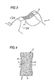
- FIG. 2 is a perspective view of a gear tooth of a worm wheel showing a state where an engagement surface of the gear tooth is subject to cutting and grinding; and FIG. 3 is a perspective view of a gear tooth of a worm wheel showing a state where reinforcing fibers are removed from the engagement surface by processing of the engagement surface.
- an engagement surface 7 to be engaged with the worm 2 is formed on a tooth surface of the gear tooth 3.
- the reinforcing fibers 8 remain on the surface.
- the reinforcing fibers 8 are required for reinforcing the mechanical properties of the synthetic resin, the reinforcing fibers 8 remaining on the engagement surface 7 causes deterioration in initial acquaintanceship or increase in driving resistance of the worm 2, as described above.
- the engagement surface 7 in order to remove the reinforcing fibers 8 from the engagement surface 7, the engagement surface 7 is so processed that a containing ratio of the reinforcing fibers 8 of the surface layer 10 is lower than that of an inner portion 9, as shown in FIG. 4.
- the surface layer 10 is so processed that a depth thereof d is larger than a diameter of the reinforcing fibers 8 and smaller than a length of the reinforcing fibers 8. Accordingly, the reinforcing fibers 8 buried in several directions on the surface of the surface layer 10 can be removed. Therefore, the reinforcing fibers 8 are not removed beyond a necessary degree thereof, and the elasticity of the engagement surface 7 in the transverse direction (the left and right directions in FIG. 4) can be easily reduced.
- a processing worm constructed by electroplating for example, natural diamond grinder powder thereon may be used.
- the processing worm is constructed by stirring the diamond grinder powder in a nickel plating bath in the electroplating process to form a coating film of the accumulated diamond grinder powder on the processing worm having the same shape of the worm 2.
- the natural diamond grinder power having a granularity of about 600 is electroplated.
- the reinforcing fibers 8 contained in the synthetic resin layer constituting the gear teeth 3 are not elastically deformed, the reinforcing fibers contacting the natural diamond grinder power electroplated on the processing worm are dug up and peeled off the synthetic resin layer.
- the base material, that is, the synthetic resin is elastically deformed, the synthetic resin are not peeled off but remained on the engagement surface 7.
- the surface layer 10 having a lower containing ratio of the reinforcing fibers 8 than the inner portion 9 is formed on the engagement surface 7.
- the natural diamond is used as a grinder powder electroplated on the processing worm in the embodiment, the invention is not limited thereto.
- a synthetic diamond, a metal-coated synthetic diamond, or the like may be used for the diamond grinder power.
- CBN grinder powder such as cubic boron nitride and metal-coated cubic boron nitride may be used as the electroplated grinder powder.
- a processing worm of which teeth surfaces are roughened with a strong acid and cured or a processing worm of which teeth surface are roughened with a long time nitrogenizing process may be used as a tool for processing the engagement surface 7, so that it is possible to obtain the same operations and effects as the processing worm on which the aforementioned diamond grinder powder is electroplated.
- the engagement surface 7 of the gear teeth 3 is so processed that the surface layer 10 having a lower containing ratio of the reinforcing fibers 8 than that of an inner portion 9 is formed on the engagement surface 7. Accordingly, a longitudinal elastic coefficient is reduced, so that it is possible to improve initial acquaintanceship (increase in teeth contact degree until a transmission torque from the worm 2 and a friction are balanced). As a result, a durability of the gear teeth 3 is greatly improved, so that it is possible to increase a durability-allowable transmission tongue.
- the reinforcing fibers 8 contained in the surface layer 10 of the engagement surface 7 are removed, it is possible to reduce a friction of the worm 2 causing a rigid contact to the reinforcing fibers 8. Accordingly, the fatigue strength of the worm 2 can be improved, so that it is possible to lengthen the lifetime of the worm 2. In addition, the hardness of the worm 2 is lowered, so that it is possible to obtain a worm having the same durable usage times as the conventional one.
- FIG. 5 is a cross sectional view of a reduction unit of an electric power steering apparatus employing the aforementioned reduction gear.
- the reduction unit 11 reduces rotation of a steering supporting electric motor 12 through a worm 2 connected to a rotating axis 13 of the electric motor 12 and a worm wheel 4 engaged with the worm 2 and transmits the reduced rotation to a steering shaft 14 fixedly inserted into a core portion 6 of the worm wheel 4.
- the reduction unit 11 employs the aforementioned reduction gear, so that it is possible to increase a durability-allowable transmission torque by which the steering supporting force of the electric motor 12 can be transmitted to the steering shaft 14. Accordingly, in terms of the steering supporting force, an electric power steering apparatus which is mainly employed by small-sized cars can be employed by medium-sized and large-sized cars requiring a large steering supporting force.
- the steering supporting force can increase, the manual steering force can be reduced, so that it is possible to obtain smooth steering feeling.
- the reduction gear is used for the electric power steering apparatus in the example, the invention is not limited thereto.
- the reduction gear may be used for reduction units of various reduction apparatuses, and the invention can be suitably applied to the reduction units.
- initial acquaintanceship of an engagement surface of a teeth gear of a worm wheel can be improved, so that it is possible to increase a durability-allowable transmission tongue.
- a friction of a worm can be reduced, so that it is possible to provide a reduction gear with the worm having a lengthened lifetime.
Landscapes
- Engineering & Computer Science (AREA)
- General Engineering & Computer Science (AREA)
- Mechanical Engineering (AREA)
- Physics & Mathematics (AREA)
- Electromagnetism (AREA)
- Thermal Sciences (AREA)
- Chemical & Material Sciences (AREA)
- Combustion & Propulsion (AREA)
- Transportation (AREA)
- Gears, Cams (AREA)
- Power Steering Mechanism (AREA)
- Gear Transmission (AREA)
Abstract
Description
- The present invention relates to a reduction gear used for electric power steering, and more particularly to, improvement of tooth surfaces of a worm wheel.
- Conventionally, a reduction gear can advantageously transmit a rotational force of an electric motor having a high rotation speed and a low torque to a steering shaft with a high reduction ratio, the reduction gear has been used for a reduction unit of an electric power steering apparatus.
- However, if a worm and a worm wheel of the reduction gear are made of a metal, there is a problem in that unpleasant noise such as teeth friction sound and vibration sound is generated during handling of a steering wheel.
- In order to solve the problem, techniques for increasing strength of gear teeth are disclosed in, for example,
Patent Documents 1 and 2. - A reduction gear (teeth gear) disclosed in Patent Document 1 is constructed with a worm made of a metal and worm wheel made of a denaturized synthetic resin containing reinforcing fibers. In the reduction gear, the synthetic resin is denaturized to increase a strength thereof, so that a containing amount of the .reinforcing fiber as a reinforcing material can be suppressed.
- In a reduction gear (teeth gear) disclosed in
Patent Document 2, aluminum stearate of 0.1 wt% to 0.3 wt% is added in a synthetic resin for a worm wheel, so that it is possible to improve smoothness of the worm wheel. - In general, in such a conventional reduction gear, nylon 6, nylon 66, or nylon 45 are used as a base material for the synthetic resin part of the worm wheel, and reinforcing fibers such as glass fibers are added to the base material, so that it is possible to reinforce mechanical properties of the synthetic resin and to suppress variation in water-absorption property of nylon.
-
- Patent Document 1:
JP-A 10-141477 - Patent Document 2:
JP-A 2002-327829 - However, the synthetic resins used for the reduction gears disclosed in
Patent Documents 1 and 2 have a higher longitudinal elastic coefficient than a non-reinforced grade one, so that the synthetic is difficult to elastically deform. Therefore, in a state where a teeth contact area of the gear teeth of the worm wheel engaged with the worm is small, initial acquaintanceship (a state of increase in teeth contact degree until a transmission torque from the worm and a friction are balanced) is set. As a result, by using the reduction gears disclosed inPatent Documents 1 and 2, it is difficult to increase a durability-allowable transmission tongue exceeding that of the reinforced grade one. - In addition, in the reduction gears disclosed in
Patent Documents 1 and 2, the reinforcing fibers are included in a surface layer of an engagement surface of the gear teeth engaged with the worm. Since a rigid contact (a contact between the reinforcing fibers included in the surface layer of the engagement surface and the metal worm) without a lubricant interposed occurs between the worm and the worm wheel, driving resistance in a large load region increases. Accordingly, since large friction is generated between the engaged worm wheel and worm, fatigue strength and friction resistance decrease, so that lifetime of the worm is shortened. - The present invention provide a reduction gear capable of increasing a durability-allowable transmission tongue by improving initial acquaintanceship of an engagement surface of a teeth gear of a worm wheel and capable of lengthening lifetime of the worm by reducing a friction of the worm.
- According to an aspect of the invention, there is provided a reduction gear including: a worm made of a metal; and a worm wheel having gear teeth engaged with the worm, wherein at least the gear teeth of the worm wheel are made of a synthetic resin containing reinforcing fibers, and wherein an engagement surface of the gear teeth is so processed that a containing ratio of the reinforcing fibers of a surface layer is lower than that of the reinforcing fiber of an inner portion.
- In the above aspect, a depth of the surface layer may be larger than a diameter of the reinforcing fibers and smaller than a length of the reinforcing fibers.
- In addition, a processing worm on which diamond grinder powder or CBN grinder powder electroplated may be engaged with the gear teeth and rotated, so that the reinforcing fibers are removed from the surface layer.
- In addition, a processing worm of which teeth surfaces are roughened with a strong acid and cured may be engaged with the engagement surface of the gear teeth and rotated, so that the reinforcing fibers are removed from the surface layer.
- In addition, a processing worm of which teeth surfaces are roughened with a nitrogenizing process may be engaged with the engagement surface of the gear teeth and rotated, so that the reinforcing fibers are removed from the surface layer.
- In addition, the worm and the worm wheel may constitute a reduction unit of an electric power steering apparatus.
- In the reduction gear according to the invention, at least the gear teeth of the worm wheel are made of a synthetic resin containing reinforcing fibers, and an engagement surface of the gear teeth is so processed that a containing ratio of the reinforcing fibers of a surface layer is lower than that of the reinforcing fiber of an inner portion. Accordingly, a longitudinal elastic coefficient of the surface layer of the engagement surface is reduced, so that it is possible to teeth contact area according to the initial acquaintanceship. As a result, a durability of the gear teeth is improved, so that it is possible to increase a durability-allowable transmission tongue.
- In addition, since a containing ratio of the reinforcing fibers of the surface layer of the engagement surface of the gear teeth can be reduced, so that it is possible to reduce a friction of the worm causing a rigid contact to the reinforcing fibers. Accordingly, a fatigue strength of the worm can be improved, so that it is possible to lengthen the lifetime of the worm. In addition, a hardness management range of a thermal process performed to obtain a desired hardness of the worm is widened at a lowered level thereof, so that it is possible to reduce production cost and labor.
- In addition, a processing worm on which diamond grinder powder or CBN grinder powder is electroplated, a processing worm of which teeth surfaces are roughened with a strong acid and cured, or a processing worm of which teeth surfaces are roughened with a long time nitrogenizing process is engaged with the engagement surface of the gear teeth and rotated, so that a depth of the surface layer can be larger than a diameter of the reinforcing fibers and smaller than a length of the reinforcing fibers. Accordingly, the reinforcing fibers buried in several directions on the surface of the surface layer can be removed. As a result, the reinforcing fibers are not removed beyond a necessary degree thereof, and the elasticity of the engagement surface in the transverse direction can be easily reduced.
- In addition, the reduction gear is used for a reduction unit of an electric power steering apparatus, so that it is possible to length lifetime of the reduction unit and to provide a large steering supporting force to a steering shaft. As a result, the electric power steering apparatus can be employed by medium-sized and large-sized cars as well as small-sized cars.
-
- [FIG. 1]
FIG. 1 is a perspective view of a reduction gear according to an embodiment of the invention. - [FIG. 2]
FIG. 2 is a perspective view of a gear tooth of a worm wheel showing a state where an engagement surface of the gear tooth is subject to cutting and grinding. - [FIG. 3]
FIG. 3 is a perspective view of a gear tooth of a worm wheel showing a state where reinforcing fibers are removed from the engagement surface. - [FIG. 4]
FIG. 4 is a cross sectional view of the gear tooth taken along line IV-IV of FIG. 3. - [FIG. 5]
FIG. 5 is a cross sectional view of a reduction unit of an electric power steering apparatus according to another embodiment employing the reduction gear. -
- 1
- reduction gear
- 2
- worm
- 3
- gear teeth
- 4
- worm wheel
- 7
- engagement surface
- 8
- reinforcing fibers
- 9
- inner portion
- 10
- surface layer
- 11
- reduction unit
- d
- depth of surface layer
- Now, embodiments of the present invention will be described with reference to the accompanying drawings.
- FIG. 1 is a perspective view of a reduction gear according to an embodiment of the invention. In the figure, the reduction gear 1 includes a
worm 2 made of a metal and a worm wheel 4 havinggear teeth 3 engaged with theworm 2. - The worm wheel 4 is integrally constructed with a resin portion 5 having a circumferential surface on which the gear teeth are formed and a core portion 6 made of a metal. The resin portion 6 is made of a synthetic resin containing reinforcing fibers. As a preferred example of the synthetic resin, there are nylon (polyamide) resins made of such as nylon 6, nylon 66, and nylon 46, phenol resins, poly acetyl reins, and the like as a base material of the synthetic resin with a mechanical property thereof reinforced with the reinforcing fibers.
- As a preferred example of the reinforcing fiber, there are glass fibers, carbon fibers, potassium titanate whisker, aluminum borate whisker, and the like. The reinforcing fibers may be used as a single one or a combination thereof. The types or mixing ratios of the base material and the reinforcing fiber of the synthetic resin may be suitably selected according to the purpose of the synthetic resin.
- In the embodiment, a portion from the circumferential surface of the core portion 60 to distal ends of the
gear tooth 3 is formed with the resin portion 5, but not limited thereto. For example, the entire portion of the worm wheel 4 may be made of the synthetic resin. Otherwise, only the circumferential portion of theworm wheel 2 on which the gear teeth are formed may be made of the synthetic resin. - FIG. 2 is a perspective view of a gear tooth of a worm wheel showing a state where an engagement surface of the gear tooth is subject to cutting and grinding; and FIG. 3 is a perspective view of a gear tooth of a worm wheel showing a state where reinforcing fibers are removed from the engagement surface by processing of the engagement surface. Referring to FIG. 2, an
engagement surface 7 to be engaged with theworm 2 is formed on a tooth surface of thegear tooth 3. Just after the cutting and grinding of theengagement surface 7, the reinforcingfibers 8 remain on the surface. Although the reinforcingfibers 8 are required for reinforcing the mechanical properties of the synthetic resin, the reinforcingfibers 8 remaining on theengagement surface 7 causes deterioration in initial acquaintanceship or increase in driving resistance of theworm 2, as described above. - Therefore, in the embodiment, in order to remove the reinforcing
fibers 8 from theengagement surface 7, theengagement surface 7 is so processed that a containing ratio of the reinforcingfibers 8 of thesurface layer 10 is lower than that of an inner portion 9, as shown in FIG. 4. Thesurface layer 10 is so processed that a depth thereof d is larger than a diameter of the reinforcingfibers 8 and smaller than a length of the reinforcingfibers 8. Accordingly, the reinforcingfibers 8 buried in several directions on the surface of thesurface layer 10 can be removed. Therefore, the reinforcingfibers 8 are not removed beyond a necessary degree thereof, and the elasticity of theengagement surface 7 in the transverse direction (the left and right directions in FIG. 4) can be easily reduced. - As a tool for processing the
engagement surface 7, a processing worm constructed by electroplating, for example, natural diamond grinder powder thereon may be used. The processing worm is constructed by stirring the diamond grinder powder in a nickel plating bath in the electroplating process to form a coating film of the accumulated diamond grinder powder on the processing worm having the same shape of theworm 2. On such a processing worm, the natural diamond grinder power having a granularity of about 600 is electroplated. By engaging the processing worm on which the natural diamond grinder powder is electroplated with theengagement surface 7 of thegear tooth 3 and rotating the processing worm, theengagement surface 7 is cut. At this time, since the reinforcingfibers 8 contained in the synthetic resin layer constituting thegear teeth 3 are not elastically deformed, the reinforcing fibers contacting the natural diamond grinder power electroplated on the processing worm are dug up and peeled off the synthetic resin layer. On the other hand, since the base material, that is, the synthetic resin is elastically deformed, the synthetic resin are not peeled off but remained on theengagement surface 7. As a result, as shown in FIG. 4, thesurface layer 10 having a lower containing ratio of the reinforcingfibers 8 than the inner portion 9 is formed on theengagement surface 7. - Although the natural diamond is used as a grinder powder electroplated on the processing worm in the embodiment, the invention is not limited thereto. Alternatively, a synthetic diamond, a metal-coated synthetic diamond, or the like may be used for the diamond grinder power. In addition, CBN grinder powder such as cubic boron nitride and metal-coated cubic boron nitride may be used as the electroplated grinder powder.
- In addition, a processing worm of which teeth surfaces are roughened with a strong acid and cured or a processing worm of which teeth surface are roughened with a long time nitrogenizing process may be used as a tool for processing the
engagement surface 7, so that it is possible to obtain the same operations and effects as the processing worm on which the aforementioned diamond grinder powder is electroplated. - Like this, in the embodiment, the
engagement surface 7 of thegear teeth 3 is so processed that thesurface layer 10 having a lower containing ratio of the reinforcingfibers 8 than that of an inner portion 9 is formed on theengagement surface 7. Accordingly, a longitudinal elastic coefficient is reduced, so that it is possible to improve initial acquaintanceship (increase in teeth contact degree until a transmission torque from theworm 2 and a friction are balanced). As a result, a durability of thegear teeth 3 is greatly improved, so that it is possible to increase a durability-allowable transmission tongue. - In addition, since the reinforcing
fibers 8 contained in thesurface layer 10 of theengagement surface 7 are removed, it is possible to reduce a friction of theworm 2 causing a rigid contact to the reinforcingfibers 8. Accordingly, the fatigue strength of theworm 2 can be improved, so that it is possible to lengthen the lifetime of theworm 2. In addition, the hardness of theworm 2 is lowered, so that it is possible to obtain a worm having the same durable usage times as the conventional one. - Now, examples employing the aforementioned reduction gear will be described, but the invention is not limited thereto. In addition, components like those of the aforementioned reduction are denoted by like reference numerals, and description thereof is omitted.
- FIG. 5 is a cross sectional view of a reduction unit of an electric power steering apparatus employing the aforementioned reduction gear. In the figure, the reduction unit 11 reduces rotation of a steering supporting
electric motor 12 through aworm 2 connected to arotating axis 13 of theelectric motor 12 and a worm wheel 4 engaged with theworm 2 and transmits the reduced rotation to asteering shaft 14 fixedly inserted into a core portion 6 of the worm wheel 4. - In the example, the reduction unit 11 employs the aforementioned reduction gear, so that it is possible to increase a durability-allowable transmission torque by which the steering supporting force of the
electric motor 12 can be transmitted to the steeringshaft 14. Accordingly, in terms of the steering supporting force, an electric power steering apparatus which is mainly employed by small-sized cars can be employed by medium-sized and large-sized cars requiring a large steering supporting force. - In addition, since the steering supporting force can increase, the manual steering force can be reduced, so that it is possible to obtain smooth steering feeling.
- Although the reduction gear is used for the electric power steering apparatus in the example, the invention is not limited thereto. The reduction gear may be used for reduction units of various reduction apparatuses, and the invention can be suitably applied to the reduction units.
- Although the invention is described in detail with reference to specific embodiments, it is obvious to the skilled in the art that the invention can be employed to various modified examples of the embodiments without departing from the spirit and scope of the invention.
The present application is based onJapanese Patent Application No. 2004-221506, filed on July 29, 2004 - According to the invention, initial acquaintanceship of an engagement surface of a teeth gear of a worm wheel can be improved, so that it is possible to increase a durability-allowable transmission tongue. In addition, according to the invention, a friction of a worm can be reduced, so that it is possible to provide a reduction gear with the worm having a lengthened lifetime.
Claims (6)
- A reduction gear comprising:a worm made of a metal; anda worm wheel having gear teeth engaged with the worm, whereat least the gear teeth of the worm wheel are made of a synthetic resin containing reinforcing fibers, andan engagement surface of the gear teeth is so processed that a containing ratio of the reinforcing fibers of a surface layer is lower than that of the reinforcing fiber of an inner portion.
- The reduction gear according to claim 1, wherein
a depth of the surface layer is larger than a diameter of the reinforcing fibers and smaller than a length of the reinforcing fibers. - The reduction gear according to claim 1 or 2, wherein
a processing worm on which diamond grinder powder or CBN grinder powder is electroplated is engaged with the engagement surface of the gear teeth and rotated, so that the reinforcing fibers are removed from the surface layer. - The reduction gear according to claim 1 or 2, wherein
a processing worm of which teeth surfaces are roughened with a strong acid and cured is engaged with the engagement surface of the gear teeth and rotated, so that the reinforcing fibers are removed from the surface layer. - The reduction gear according to claim 1 or 2, wherein
a processing worm of which teeth surfaces are roughened with a nitrogenizing process is engaged with the engagement surface of the gear teeth and rotated, so that the reinforcing fibers are removed from the surface layer. - The reduction gear according to any one of claims 1 to 5, wherein
the worm and the worm wheel constitute a reduction unit of an electric power steering apparatus.
Applications Claiming Priority (2)
| Application Number | Priority Date | Filing Date | Title |
|---|---|---|---|
| JP2004221506A JP4665450B2 (en) | 2004-07-29 | 2004-07-29 | Reduction gear |
| PCT/JP2005/013939 WO2006011596A1 (en) | 2004-07-29 | 2005-07-29 | Speed reduction gear |
Publications (3)
| Publication Number | Publication Date |
|---|---|
| EP1780444A1 true EP1780444A1 (en) | 2007-05-02 |
| EP1780444A4 EP1780444A4 (en) | 2011-03-02 |
| EP1780444B1 EP1780444B1 (en) | 2012-04-18 |
Family
ID=35786342
Family Applications (1)
| Application Number | Title | Priority Date | Filing Date |
|---|---|---|---|
| EP05767262A Expired - Lifetime EP1780444B1 (en) | 2004-07-29 | 2005-07-29 | Speed reduction gear |
Country Status (4)
| Country | Link |
|---|---|
| US (1) | US20080314180A1 (en) |
| EP (1) | EP1780444B1 (en) |
| JP (1) | JP4665450B2 (en) |
| WO (1) | WO2006011596A1 (en) |
Cited By (1)
| Publication number | Priority date | Publication date | Assignee | Title |
|---|---|---|---|---|
| DE102017122896A1 (en) | 2017-10-02 | 2019-04-04 | Thyssenkrupp Ag | Worm wheel for a worm gear of a motor vehicle steering system made of fiber-reinforced plastic with specific orientation of the fibers |
Families Citing this family (7)
| Publication number | Priority date | Publication date | Assignee | Title |
|---|---|---|---|---|
| JP4941347B2 (en) * | 2008-02-18 | 2012-05-30 | 日本精工株式会社 | Worm wheel and processing method thereof |
| JP4944941B2 (en) * | 2009-12-21 | 2012-06-06 | 日立オートモティブシステムズ株式会社 | Worm wheel |
| JP4973774B2 (en) * | 2010-11-09 | 2012-07-11 | 日本精工株式会社 | Worm reducer and electric power steering device |
| WO2013073313A1 (en) * | 2011-11-16 | 2013-05-23 | 本田技研工業株式会社 | Worm gear mechanism |
| CN104295709A (en) * | 2014-09-19 | 2015-01-21 | 常州市武进金城齿轮有限公司 | Heat-dissipation copper worm gear |
| JP2021196038A (en) * | 2020-06-17 | 2021-12-27 | 住友重機械工業株式会社 | Gear device |
| JP7762502B2 (en) | 2020-11-27 | 2025-10-30 | 住友重機械工業株式会社 | Resin gears and gear devices |
Family Cites Families (19)
| Publication number | Priority date | Publication date | Assignee | Title |
|---|---|---|---|---|
| US3180171A (en) * | 1962-03-06 | 1965-04-27 | American Plastics Corp | Thermoplastic resin covered gear and method of making same |
| JPH07506301A (en) * | 1993-02-18 | 1995-07-13 | キャタピラー インコーポレイテッド | Grinding and finishing worm |
| JPH10141477A (en) * | 1996-11-07 | 1998-05-29 | Koyo Seiko Co Ltd | Synthetic resin gear |
| DE19712287C1 (en) * | 1997-03-24 | 1998-08-20 | Deutsch Zentr Luft & Raumfahrt | Toothed component |
| JP2000084747A (en) * | 1998-09-17 | 2000-03-28 | Showa Corp | Processing method of resin gear with bone |
| JP3765208B2 (en) * | 1999-09-08 | 2006-04-12 | 株式会社ジェイテクト | Electric steering device |
| JP2001304379A (en) * | 2000-04-20 | 2001-10-31 | Unisia Jecs Corp | Synthetic resin gear and manufacturing method thereof |
| JP3496119B2 (en) * | 2000-07-27 | 2004-02-09 | 光洋精工株式会社 | Electric steering device |
| US6602115B2 (en) * | 2001-01-03 | 2003-08-05 | The Boeing Company | Tool and method for precision grinding of a conical face gear that meshes with a conical involute pinion |
| JP4918954B2 (en) | 2001-05-01 | 2012-04-18 | 株式会社ジェイテクト | Electric power steering device |
| JP2003139220A (en) * | 2001-11-02 | 2003-05-14 | Nsk Ltd | Worm wheel and method of manufacturing the same |
| DE10157639A1 (en) * | 2001-11-24 | 2003-06-05 | Zf Lenksysteme Gmbh | Gearboxes, especially superimposed gearboxes for steering systems |
| JP4281303B2 (en) * | 2002-03-20 | 2009-06-17 | 日本精工株式会社 | Reduction gear for electric power steering device |
| JP2003335250A (en) * | 2002-05-22 | 2003-11-25 | Nsk Ltd | Reduction gears for electric power steering devices |
| JP2004155245A (en) * | 2002-11-05 | 2004-06-03 | Nsk Ltd | Electric power steering device |
| WO2005046957A1 (en) * | 2003-11-14 | 2005-05-26 | Ogura Clutch Co., Ltd. | Resin coating method, insert molding, and resin coated metal gears |
| JP2005214338A (en) * | 2004-01-30 | 2005-08-11 | Mitsuboshi Belting Ltd | Resin worm wheel and its manufacturing method |
| WO2006126627A1 (en) * | 2005-05-25 | 2006-11-30 | Asahi Organic Chemicals Industry Co., Ltd. | Resin gear for electric power steering system and electric power steering system comprising same |
| JP2009121499A (en) * | 2007-11-12 | 2009-06-04 | Hitachi Ltd | Worm gear and electric power steering device |
-
2004
- 2004-07-29 JP JP2004221506A patent/JP4665450B2/en not_active Expired - Lifetime
-
2005
- 2005-07-29 WO PCT/JP2005/013939 patent/WO2006011596A1/en not_active Ceased
- 2005-07-29 EP EP05767262A patent/EP1780444B1/en not_active Expired - Lifetime
- 2005-07-29 US US11/658,745 patent/US20080314180A1/en not_active Abandoned
Cited By (1)
| Publication number | Priority date | Publication date | Assignee | Title |
|---|---|---|---|---|
| DE102017122896A1 (en) | 2017-10-02 | 2019-04-04 | Thyssenkrupp Ag | Worm wheel for a worm gear of a motor vehicle steering system made of fiber-reinforced plastic with specific orientation of the fibers |
Also Published As
| Publication number | Publication date |
|---|---|
| JP4665450B2 (en) | 2011-04-06 |
| JP2006038158A (en) | 2006-02-09 |
| US20080314180A1 (en) | 2008-12-25 |
| EP1780444B1 (en) | 2012-04-18 |
| WO2006011596A1 (en) | 2006-02-02 |
| EP1780444A4 (en) | 2011-03-02 |
Similar Documents
| Publication | Publication Date | Title |
|---|---|---|
| EP1780444B1 (en) | Speed reduction gear | |
| US6863135B2 (en) | Electric power tool | |
| KR20080007651A (en) | Resin gear for electric power steering and electric power steering with same | |
| WO2006011534A1 (en) | Speed-reduction gear | |
| EP1083112A2 (en) | Electric power steering apparatus | |
| JPH09280345A (en) | Pulley and manufacture thereof | |
| JP2009041683A (en) | Resinous worm wheel | |
| EP0240936A2 (en) | V Belt | |
| CN102414457A (en) | Key connecting mechanism | |
| JP2003083423A (en) | Reduction gears for electric power steering devices | |
| JPH10141477A (en) | Synthetic resin gear | |
| KR20170138659A (en) | Reducer of Power Steering Apparatus for Vehicle | |
| JP2002195351A (en) | High load transmission belt and block for high load transmission belt | |
| JPH0893858A (en) | V-belt for continuously variable transmission | |
| JP2003322217A (en) | High-load transmission belt | |
| JP2953203B2 (en) | Fiber reinforced resin gear | |
| CN209743369U (en) | High-strength rotating shaft with stable axial lead | |
| JP2004028200A (en) | High-load transmission belt | |
| JP2004003531A (en) | Heavy duty transmitting belt | |
| JP2014141232A (en) | Reduction gear for electric power steering device | |
| JP2006290062A (en) | Reduction gear for electric power steering device | |
| KR102011653B1 (en) | Reducer of Power Steering Apparatus for Vehicle | |
| JP2002327829A (en) | Gear and motor-driven power steering device provided with this | |
| JP2004052840A (en) | Reduction gears for electric power steering devices | |
| JP2002061716A (en) | High load transmission belt |
Legal Events
| Date | Code | Title | Description |
|---|---|---|---|
| PUAI | Public reference made under article 153(3) epc to a published international application that has entered the european phase |
Free format text: ORIGINAL CODE: 0009012 |
|
| 17P | Request for examination filed |
Effective date: 20070126 |
|
| AK | Designated contracting states |
Kind code of ref document: A1 Designated state(s): DE FR |
|
| DAX | Request for extension of the european patent (deleted) | ||
| RBV | Designated contracting states (corrected) |
Designated state(s): DE FR |
|
| A4 | Supplementary search report drawn up and despatched |
Effective date: 20110202 |
|
| GRAP | Despatch of communication of intention to grant a patent |
Free format text: ORIGINAL CODE: EPIDOSNIGR1 |
|
| GRAS | Grant fee paid |
Free format text: ORIGINAL CODE: EPIDOSNIGR3 |
|
| GRAA | (expected) grant |
Free format text: ORIGINAL CODE: 0009210 |
|
| AK | Designated contracting states |
Kind code of ref document: B1 Designated state(s): DE FR |
|
| REG | Reference to a national code |
Ref country code: DE Ref legal event code: R096 Ref document number: 602005033756 Country of ref document: DE Effective date: 20120614 |
|
| PLBE | No opposition filed within time limit |
Free format text: ORIGINAL CODE: 0009261 |
|
| STAA | Information on the status of an ep patent application or granted ep patent |
Free format text: STATUS: NO OPPOSITION FILED WITHIN TIME LIMIT |
|
| 26N | No opposition filed |
Effective date: 20130121 |
|
| REG | Reference to a national code |
Ref country code: DE Ref legal event code: R097 Ref document number: 602005033756 Country of ref document: DE Effective date: 20130121 |
|
| REG | Reference to a national code |
Ref country code: FR Ref legal event code: PLFP Year of fee payment: 12 |
|
| REG | Reference to a national code |
Ref country code: FR Ref legal event code: PLFP Year of fee payment: 13 |
|
| REG | Reference to a national code |
Ref country code: FR Ref legal event code: PLFP Year of fee payment: 14 |
|
| PGFP | Annual fee paid to national office [announced via postgrant information from national office to epo] |
Ref country code: FR Payment date: 20190619 Year of fee payment: 15 |
|
| PG25 | Lapsed in a contracting state [announced via postgrant information from national office to epo] |
Ref country code: FR Free format text: LAPSE BECAUSE OF NON-PAYMENT OF DUE FEES Effective date: 20200731 |
|
| PGFP | Annual fee paid to national office [announced via postgrant information from national office to epo] |
Ref country code: DE Payment date: 20240604 Year of fee payment: 20 |
|
| REG | Reference to a national code |
Ref country code: DE Ref legal event code: R071 Ref document number: 602005033756 Country of ref document: DE |