EP1780413A2 - Method and equipment for detecting failure in oil film formation of swash plate compressor - Google Patents
Method and equipment for detecting failure in oil film formation of swash plate compressor Download PDFInfo
- Publication number
- EP1780413A2 EP1780413A2 EP06122846A EP06122846A EP1780413A2 EP 1780413 A2 EP1780413 A2 EP 1780413A2 EP 06122846 A EP06122846 A EP 06122846A EP 06122846 A EP06122846 A EP 06122846A EP 1780413 A2 EP1780413 A2 EP 1780413A2
- Authority
- EP
- European Patent Office
- Prior art keywords
- swash plate
- piston
- voltage
- oil film
- film formation
- Prior art date
- Legal status (The legal status is an assumption and is not a legal conclusion. Google has not performed a legal analysis and makes no representation as to the accuracy of the status listed.)
- Withdrawn
Links
- 230000015572 biosynthetic process Effects 0.000 title claims abstract description 46
- 238000000034 method Methods 0.000 title claims description 9
- 230000005611 electricity Effects 0.000 claims description 11
- 239000010408 film Substances 0.000 description 48
- 239000003507 refrigerant Substances 0.000 description 18
- 238000001514 detection method Methods 0.000 description 8
- 239000000314 lubricant Substances 0.000 description 3
- 239000002184 metal Substances 0.000 description 3
- 230000001105 regulatory effect Effects 0.000 description 3
- 238000004378 air conditioning Methods 0.000 description 2
- 238000005461 lubrication Methods 0.000 description 2
- 238000012545 processing Methods 0.000 description 2
- 230000005856 abnormality Effects 0.000 description 1
- 239000011248 coating agent Substances 0.000 description 1
- 238000000576 coating method Methods 0.000 description 1
- 239000004020 conductor Substances 0.000 description 1
- 230000003247 decreasing effect Effects 0.000 description 1
- 238000007599 discharging Methods 0.000 description 1
- 238000003780 insertion Methods 0.000 description 1
- 230000037431 insertion Effects 0.000 description 1
- 238000012423 maintenance Methods 0.000 description 1
- 238000012544 monitoring process Methods 0.000 description 1
- 230000003287 optical effect Effects 0.000 description 1
- 230000002093 peripheral effect Effects 0.000 description 1
- 239000010409 thin film Substances 0.000 description 1
Images


Classifications
-
- F—MECHANICAL ENGINEERING; LIGHTING; HEATING; WEAPONS; BLASTING
- F04—POSITIVE - DISPLACEMENT MACHINES FOR LIQUIDS; PUMPS FOR LIQUIDS OR ELASTIC FLUIDS
- F04B—POSITIVE-DISPLACEMENT MACHINES FOR LIQUIDS; PUMPS
- F04B27/00—Multi-cylinder pumps specially adapted for elastic fluids and characterised by number or arrangement of cylinders
- F04B27/08—Multi-cylinder pumps specially adapted for elastic fluids and characterised by number or arrangement of cylinders having cylinders coaxial with, or parallel or inclined to, main shaft axis
- F04B27/10—Multi-cylinder pumps specially adapted for elastic fluids and characterised by number or arrangement of cylinders having cylinders coaxial with, or parallel or inclined to, main shaft axis having stationary cylinders
- F04B27/1036—Component parts, details, e.g. sealings, lubrication
- F04B27/109—Lubrication
-
- F—MECHANICAL ENGINEERING; LIGHTING; HEATING; WEAPONS; BLASTING
- F04—POSITIVE - DISPLACEMENT MACHINES FOR LIQUIDS; PUMPS FOR LIQUIDS OR ELASTIC FLUIDS
- F04B—POSITIVE-DISPLACEMENT MACHINES FOR LIQUIDS; PUMPS
- F04B51/00—Testing machines, pumps, or pumping installations
Definitions
- the present invention relates to a method and equipment for detecting failure in oil film formation of a swash plate compressor used in a refrigerant circuit of an air conditioner for a vehicle, for example.
- this type of swash plate compressor is known as comprising a plurality of cylinders provided with an interval to each other in the circumferential direction in a compressor body, a plurality of pistons reciprocating in each cylinder, respectively, a swash plate slidably engaging with one end side of each piston, and a driving shaft for rotating the swash plate, in which the one end side of each piston is slidably brought into contact with the swash plate through a pair of shoes opposed to each other having the swash plate between them (See Japanese Utility Model Laid-Open No. 4-125682 , for example).
- the present invention was made in view of the above problems, and its object is to provide a method and equipment for detecting failure in oil film formation of a swash plate compressor which can detect a failure in oil film formation with accuracy in operation of the compressor, respond to various operating conditions and is further capable of detection without affecting performance of the compressor.
- a voltage of a predetermined constant voltage power supply is applied from outside through a voltage application circuit to conducting means for conducting electricity to the shoe of the piston and the swash plate and a voltage value of the voltage application circuit is measured so as to determine if a value of the measured voltage is equal to or larger than a predetermined reference value or not.
- a swash plate compressor comprising a plurality of cylinders provided with an interval to each other in the circumferential direction in a compressor body, a piston reciprocating in each cylinder, a swash plate slidably engaging with one end side of the piston, and a driving shaft for rotating the swash plate, in which the one end side of the piston is slidably engaged with the swash plate through a pair of shoes opposing each other with the swash plate between them, there are provided first conducting means for conducting electricity to the shoe of the piston, second conducting means for conducting electricity to the swash plate, a voltage application circuit connected from the outside to the first and the second conducting means for applying a voltage of a predetermined intensity to the first and the second conducting means, a voltage measuring instrument for measuring a voltage value of the voltage application circuit, and a determining processor for determining if the value of the measured voltage of the voltage measuring instrument is equal to or larger than a predetermined reference
- the failure in oil film formation can be detected without installing precision equipment such as a sensor, camera or transmitter inside the compressor body, the failure in oil film formation can be detected more surely with a simple structure. Therefore, the failure in the oil film formation canbe detected with accuracy in operation of the compressor, diversified operating conditions can be responded, and moreover, the failure in oil film formation can be detected without affecting performance of the compressor, which is extremely advantageous in practical application.
- FIGS. 1 to 6 show an embodiment of the present invention.
- a swash plate compressor shown in them comprises a compressor body 10 suctioning and discharging a refrigerant, a plurality of pistons 20 provided inside the compressor body 10, a swash plate 30 slidably engaged with one end side of each piston 20, and a driving shaft 40 for rotating the swash plate 30.
- the compressor body 10 comprises a housing 11, a cylinder block 12, a cylinder head 13 and a valve plate 14, which are coupled with each other in the axial direction by a bolt, not shown.
- the housing 11 is formed in the cylindrical state with one end side blocked, while the other end side is opened on the cylinder block 12 side.
- the cylinder block 12 has a plurality of cylinders 12a extending in the axial direction of the compressor body 10, and both ends of each cylinder 12a are opened on the housing 11 side and the valve plate 14 side, respectively.
- the cylinder head 13 has a refrigerant discharge chamber 13a and a refrigerant suction chamber 13b, and the refrigerant discharge chamber 13a and the refrigerant suction chamber 13b are opened on the cylinder block 12 side, respectively.
- the refrigerant discharge chamber 13a is provided at a center portion of the cylinder head 13 and communicates with a discharge port (not shown) to the outside.
- the refrigerant suction chamber 13b is provided in the periphery of the refrigerant discharge chamber 13a and communicates with a suction port (not shown) from the outside.
- the valve plate 14 is arranged between the cylinder block 12 and the cylinder head 13 and has a plurality of refrigerant discharge holes 14a and refrigerant suction holes 14b communicating with each cylinder 12a.
- a discharge-side plate 14c is arranged, and on the discharge-side plate 14c, a discharge valve (not shown) for opening/closing each refrigerant discharge hole 14a is provided.
- a suction-side plate 14d is arranged, and on the suction-side plate 14d, a suction valve (not shown) for opening/closing each refrigerant suction hole 14b is provided.
- Each piston 20 is provided slidably in each cylinder 12a with an engagement portion 21 to be engaged with the swash plate 30 formed at its one end.
- the engagement portion 21 has a pair of semispherical faces opposed to each other, and a semispherical shoe 22 is slidably provided between each semispherical face.
- the swash plate 30 is provided capable of inclination with respect to the axial direction of the driving shaft 40, and with its peripheral edge portion, the engagement portion 21 of each piston 20 is engaged slidably through the shoe 22.
- the swash plate 30 is coupled capable of inclination to a rotating plate 31 rotating integrally with the driving shaft 40 so as to rotate around the driving shaft 40 by the rotating plate 31 and to reciprocate each piston 20 by a stroke amount corresponding to its inclination angle.
- an oil film by a lubricant circuiting inside the compressor body 10.
- a non-compressed surface (the surface not receiving a reaction force of the piston 20) of the swash plate 30 is covered by a thin-film insulating member 30a so that the non-compressed surface of the swash plate 30 and one of the shoes 22 are electrically insulated by the insulating member 30a.
- electricity is conducted only through the compressed surface (the surface receiving the reaction force of the piston 20) of the swash plate 30 and the other shoe 22.
- the non-compressed surface of the swash plate 30 may be given surface processing made of insulating coating.
- the driving shaft 40 is rotatably supported by the housing 11 at its one end side through a bearing 41, while the other end side is rotatably supported by the cylinder block 12 through a bearing 42.
- This equipment for detecting failure in oil film formation 50 comprises a terminal 51 provided on the outer face side of the housing 11, a conductive member 52 provided on the side of the piston 20, a contact pin 53 as a contact member provided at the piston 20, a voltage application circuit 54 for applying a voltage of a predetermined intensity to each shoe 22 and the swash plate 30, a voltage measuring instrument 55 for measuring a voltage value of the voltage application circuit 54, and a determining processor 56 for determining if the measured voltage of the voltage measuring instrument 55 is equal to or larger than a predetermined reference value or not, and the terminal 51, the conductive member 52 and the contact pin 53 are provided on both sides in the width direction of the piston 20, respectively.
- the terminal 51 has a screw hole 51a for bolt screwing, and a conductor, not shown, of the voltage application circuit 54 is connected.
- the conductive member 52 is made of a metal member extending in the sliding direction of the piston 20 and fastened to the housing 11 by a bolt 52a screwed to the terminal 51.
- the bolt 52a is screwed to the terminal 51 by insertion through a through hole 11a provided at the housing 11, and a sleeve 52b which insulates the bolt 52a and the housing 11 is inserted through the through hole 11a.
- an insulating film 52c is formed on the inner circumferential face of the housing 11, and the conductive member 52 and the housing 11 are insulated by the insulating film 52c.
- the contact pin 53 is made of conductive metal and slidably inserted into a hole 20a provided on the side face of the piston 20.
- a spring 53a is provided within the hole 20a so that the contact pin 53 is pressed into contact with the side face of the conductive member 52 by the spring 53a.
- a conducting spring 57 as an elastic member conductive with the shoe 22 is provided, and the conducting spring 57 is fixed to the piston 20 so that its one end contacts the other shoe 22.
- the voltage application circuit 54 comprises a constant voltage power supply 54a and a variable resistor 54b connected in series, and the constant voltage power supply 54a generates a direct current voltage with a predetermined intensity (2.0 [V], for example).
- the voltage application circuit 54 is connected to the terminal 51 at one end side (the variable resistor 54b side) with the other end side (the power supply 54a side) to the housing 11 of the compressor body 10.
- the voltage measuring instrument 55 is connected to the voltage application circuit 54 in parallel with the variable resistor 54b so as to measure the voltage of the variable resistor 54b.
- the determining processor 56 is connected to the voltage measuring instrument 55 so as to determine whether the voltage value measured by the voltage measuring instrument 55 is equal to or larger than a predetermined reference voltage value V (1.9 [V], for example) or not.
- the terminal 51, the conductive member 52, the contact pin 53, the piston 20 and the shoe 22 are conducted sequentially as first conducting means, and the housing 11 of the compressor body 10, the driving shaft 40 and the swash plate 30 are conducted sequentially as second conducting means.
- the piston 20 and the shoe 22 are also conducted by the conducting spring 57.
- each piston 20 reciprocates within each cylinder 12a according to the inclination angle of the swash plate 30.
- the refrigerant of the refrigerant suction chamber 13b is sucked into each cylinder 12a and discharged into the refrigerant discharge chamber 13a.
- a pressure inside the housing 11 is regulated by pressure control means, not shown, and by a differential pressure generated between the refrigerant suction chamber 13b and the inside of the housing 11, the inclination angle of the swash plate 30 is changed according to the pressure applied on the other end side (the side of the housing 11) of each piston 20.
- a stroke amount of each piston 20 is increased or decreased, and the discharge amount of the refrigerant is changed.
- the voltage of the power supply 54a of the voltage application circuit 54 is applied to each shoe 22 and the swash plate 30, and the voltage of the variable resistor 54b is measured by the voltage measuring instrument 55.
- this clearance becomes electric resistance and the value of the measured voltage becomes smaller than the voltage of the power supply 54a. That is, as shown in FIG.
- the voltage of a predetermined intensity is applied by the voltage application circuit 54 to each shoe 22 of the piston 20 and the swash plate 30 from the outside and the voltage value of the voltage application circuit 54 is measured by the voltage measuring instrument 55.
- the failure in formation of an oil film between the shoe 22 and the swash plate 30 is detected by determining whether the value of the measured voltage is equal to or larger than the predetermined reference value or not by the determining processor 56, there is no need to install precision equipment such as a sensor, camera or transmitter inside the compressor body 10, and the failure in oil film formation can be detected more surely with a simple structure. Therefore, the failure in oil film formation can be detected with accuracy in operation of the compressor, diversified operating conditions can be responded, and moreover, the failure in oil film formation can be detected without affecting performance of the compressor, which is extremely advantageous in practical realization.
- a failure in oil film formation can be easily detected by connecting the voltage application circuit 54 to the compressor from the outside, not only that it can be provided in an air conditioning device for a vehicle for detecting a failure in oil film formation of a compressor mounted on a vehicle but even though it is not provided in the air conditioning device for a vehicle, the failure in oil film formation can be easily detected by connecting the voltage application circuit 54 to the compressor at shipment from a plant or maintenance, which can improve versatility.
- the terminal 51, the conductive member 52, the contact pin 53, the piston 20 and the shoe 22 are sequentially conducted by providing the terminal 51 to which the one end side of the voltage application circuit 54 can be connected on the outer surface side of the compressor body 10, providing the conductive member 52 conductive to the terminal 51 on the side of the piston 20, and by providing the conductive contact pin 53 slidably contacting the conductive member 52 at the piston 20, the one end side of the voltage application circuit 54 can be made conductive to the shoe 22 only by adding a simple part such as the terminal 51, the conductive member 52 and the contact pin 53, which is extremely advantageous for cost reduction.
- the compressor body 10 since the compressor body 10, the driving shaft 40 and the swash plate 30 are sequentially conducted, the other end side of the voltage application circuit 54 can be conducted to the swash plate 30 only by connecting the other end side of the voltage application circuit 54 to the compressor body 10 without adding an exclusive conductive part, which is extremely advantageous for cost reduction.
- each contact pin 53 is pressed into contact with the conductive member 52 by the spring 53a, the contact pin 53 can be surely brought into contact with the conductive member 52, and conducting between the conductive member 52 and the contact pin 53 can be made surely.
- the conductive member 52 and the contact pin 53 are provided on both sides in the width direction of the piston 20, respectively, even if the piston 20 is displaced in the width direction during a reciprocating motion, one of the contact pins 53 can be brought into contact with either one of the conductive members 52 all the time, and conducting between the conductive member 52 and the contact pin 53 can be made more surely.
- the circumferential rotation of the piston 20 can be regulated by each conductive member 52 arranged on both sides in the width direction, the piston 20 can be reciprocated stably all the time without separately providing a part for preventing rotation.
- the conducting spring 57 with the one end in contact with the other shoe 22 is provided at the piston 20 so that the piston 20 and the other shoe 22 are also conducted by the conducting spring 57, the conducting between the piston 20 and the shoe 22 can be made more surely, and drop of conductivity caused by the oil film between the piston 20 and the other shoe 22 can be surely prevented.
- the voltage value of the variable resistor 54b provided at the voltage application circuit 54 is measured by the voltage measuring instrument 55, the correlation between the voltage and the clearance between the swash plate/shoe shown in FIG. 6 can be arbitrarily set by regulating the resistance value of the variable resistor 54b.
- the one face (non-compressed surface) of the swash plate 30 is insulated from the one shoe 22 by the insulating member 30a, only between the other face (compressed surface) of the swash plate 30 and the other shoe 22 can be conducted, and a failure in oil film formation on the compressed surface side of the swash plate 30 where lubrication state is demanding can be surely detected.
- the conductive member 52 and the contact pin 53 of the equipment for detecting failure in oil film formation in the above embodiment may be provided at each piston 20, but they may be provided only some of the pistons 20.
Landscapes
- Engineering & Computer Science (AREA)
- Mechanical Engineering (AREA)
- General Engineering & Computer Science (AREA)
- Compressors, Vaccum Pumps And Other Relevant Systems (AREA)
- Control Of Positive-Displacement Pumps (AREA)
Abstract
Description
- The present invention relates to a method and equipment for detecting failure in oil film formation of a swash plate compressor used in a refrigerant circuit of an air conditioner for a vehicle, for example.
- Generally, this type of swash plate compressor is known as comprising a plurality of cylinders provided with an interval to each other in the circumferential direction in a compressor body, a plurality of pistons reciprocating in each cylinder, respectively, a swash plate slidably engaging with one end side of each piston, and a driving shaft for rotating the swash plate, in which the one end side of each piston is slidably brought into contact with the swash plate through a pair of shoes opposed to each other having the swash plate between them (See
Japanese Utility Model Laid-Open No. 4-125682 - Also, in the above compressor, an oil film of a lubricant is formed between each shoe and the swash plate, but since the shoe and the swash plate mutually slide at a high speed, the lubrication condition is demanding, and there is a problem that seizing between metal easily occurs due to lack of oil film. Then, in order to detect a failure in oil film formation between the shoe and the swash plate, there are proposed a method of measuring a clearance from the shoe by embedding a sensor in the swash plate, a method of direct monitoring of a sliding portion using a high-speed camera, a method of external detection by outputting an optical signal or an electric wave signal when the shoe and the swash plate are brought into contact with each other and the like.
- However, in each of the above detecting methods, since precision equipment such as a sensor, camera or transmitter is installed inside the compressor, there are various problems in making it into practice on whether accurate detection is possible while the compressor is operating, various operating conditions can be met or detection without affecting performance of the compressor is possible or not.
- The present invention was made in view of the above problems, and its object is to provide a method and equipment for detecting failure in oil film formation of a swash plate compressor which can detect a failure in oil film formation with accuracy in operation of the compressor, respond to various operating conditions and is further capable of detection without affecting performance of the compressor.
- In order to achieve the above object, in a method for detecting a failure in oil film formation of a swash plate compressor comprising a plurality of cylinders provided with an interval to each other in the circumferential direction in a compressor body, a piston reciprocating in each cylinder, a swash plate slidably engaging with one end side of the piston, and a driving shaft for rotating the swash plate, in which the one end side of the piston is slidably engaged with the swash plate through a pair of shoes opposing each other with the swash plate between them, a voltage of a predetermined constant voltage power supply is applied from outside through a voltage application circuit to conducting means for conducting electricity to the shoe of the piston and the swash plate and a voltage value of the voltage application circuit is measured so as to determine if a value of the measured voltage is equal to or larger than a predetermined reference value or not.
- By this, when a voltage of power supply of the voltage application circuit is applied to the shoe and the swash plate, a clearance by an oil film between the shoe and the swash plate forms electric resistance and the value of the voltage application circuit becomes smaller than the voltage of constant voltage power supply. But if the thickness of the oil film becomes smaller, the electric resistance drops and the voltage value becomes larger. Thus, in the state of lack of oil film or close to it, the voltage value of the voltage application circuit becomes substantially equal to the voltage value of the constant voltage power supply. By this, since it is determined that the value of measured voltage becomes equal to or larger than the reference voltage value when the voltage value of the voltage application circuit becomes equal to or larger than a reference voltage value, detection of a failure in oil film formation becomes possible based on the determination result. Therefore, detection of a failure in the oil film formation can be made without installing precision equipment such as a sensor, camera or transmitter inside the compressor body.
- Also, in order to achieve the above object, in equipment for detecting failure in oil film formation of a swash plate compressor comprising a plurality of cylinders provided with an interval to each other in the circumferential direction in a compressor body, a piston reciprocating in each cylinder, a swash plate slidably engaging with one end side of the piston, and a driving shaft for rotating the swash plate, in which the one end side of the piston is slidably engaged with the swash plate through a pair of shoes opposing each other with the swash plate between them, there are provided first conducting means for conducting electricity to the shoe of the piston, second conducting means for conducting electricity to the swash plate, a voltage application circuit connected from the outside to the first and the second conducting means for applying a voltage of a predetermined intensity to the first and the second conducting means, a voltage measuring instrument for measuring a voltage value of the voltage application circuit, and a determining processor for determining if the value of the measured voltage of the voltage measuring instrument is equal to or larger than a predetermined reference value.
- By this, when a voltage of power supply of the voltage application circuit is applied to the shoe and the swash plate through the first and the second conducting means, a clearance by the oil film between the shoe and the swash plate forms electric resistance and the value of the voltage application circuit becomes smaller than the voltage of constant voltage power supply, but if the thickness of the oil film becomes smaller, the electric resistance drops and the voltage value increases. Thus, in the state of lack of oil film or close to it, the voltage value of the voltage application circuit becomes substantially equal to the voltage value of the constant voltage power supply. By this, when the voltage value of the voltage application circuit becomes equal to or larger than the reference voltage value, it is determined by the determining processor that the value of the measured voltage of the voltage measuring instrument becomes equal to or larger than the reference voltage value, and detection of a failure in oil film formation can be made possible based on the determination result. Therefore, detection of a failure in the oil film formation can be made without installing precision equipment such as a sensor, camera or transmitter inside the compressor body.
- According to the present invention, since a failure in the oil film formation can be detected without installing precision equipment such as a sensor, camera or transmitter inside the compressor body, the failure in oil film formation can be detected more surely with a simple structure. Therefore, the failure in the oil film formation canbe detected with accuracy in operation of the compressor, diversified operating conditions can be responded, and moreover, the failure in oil film formation can be detected without affecting performance of the compressor, which is extremely advantageous in practical application.
- The above object as well as the other objects, features and advantages of the present invention will be made clear in the following description and the attached drawings.
- In the Drawings;
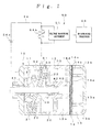
- FIG. 1 is an outline side view of equipment for detecting failure in oil film formation showing an embodiment of the present invention;
- FIG. 2 is a sectional view of an essential part of the equipment for detecting failure in oil film formation;
- FIG. 3 is an enlarged sectional view of the essential part of the equipment for detecting failure in oil film formation;
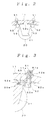
- FIG. 4 is a side view of a piston;
- FIG. 5 is a partially exploded side view of the piston;
- FIG. 6 is a graph showing a relation between a voltage and a clearance; and
- FIG. 7 is a partially exploded side view showing another embodiment of the present invention.
- FIGS. 1 to 6 show an embodiment of the present invention. A swash plate compressor shown in them comprises a
compressor body 10 suctioning and discharging a refrigerant, a plurality ofpistons 20 provided inside thecompressor body 10, aswash plate 30 slidably engaged with one end side of eachpiston 20, and adriving shaft 40 for rotating theswash plate 30. - The
compressor body 10 comprises ahousing 11, acylinder block 12, acylinder head 13 and avalve plate 14, which are coupled with each other in the axial direction by a bolt, not shown. - The
housing 11 is formed in the cylindrical state with one end side blocked, while the other end side is opened on thecylinder block 12 side. - The
cylinder block 12 has a plurality of cylinders 12a extending in the axial direction of thecompressor body 10, and both ends of each cylinder 12a are opened on thehousing 11 side and thevalve plate 14 side, respectively. - The
cylinder head 13 has a refrigerant discharge chamber 13a and a refrigerant suction chamber 13b, and the refrigerant discharge chamber 13a and the refrigerant suction chamber 13b are opened on thecylinder block 12 side, respectively. The refrigerant discharge chamber 13a is provided at a center portion of thecylinder head 13 and communicates with a discharge port (not shown) to the outside. The refrigerant suction chamber 13b is provided in the periphery of the refrigerant discharge chamber 13a and communicates with a suction port (not shown) from the outside. - The
valve plate 14 is arranged between thecylinder block 12 and thecylinder head 13 and has a plurality of refrigerant discharge holes 14a and refrigerant suction holes 14b communicating with each cylinder 12a. On one face side of the valve plate 14 (on the side of the cylinder head 13), a discharge-side plate 14c is arranged, and on the discharge-side plate 14c, a discharge valve (not shown) for opening/closing each refrigerant discharge hole 14a is provided. Also, on the other face side of the valve plate 14 (on the side of the cylinder block 12), a suction-side plate 14d is arranged, and on the suction-side plate 14d, a suction valve (not shown) for opening/closing each refrigerant suction hole 14b is provided. - Each
piston 20 is provided slidably in each cylinder 12a with anengagement portion 21 to be engaged with theswash plate 30 formed at its one end. Theengagement portion 21 has a pair of semispherical faces opposed to each other, and asemispherical shoe 22 is slidably provided between each semispherical face. - The
swash plate 30 is provided capable of inclination with respect to the axial direction of the drivingshaft 40, and with its peripheral edge portion, theengagement portion 21 of eachpiston 20 is engaged slidably through theshoe 22. Theswash plate 30 is coupled capable of inclination to a rotating plate 31 rotating integrally with the drivingshaft 40 so as to rotate around thedriving shaft 40 by the rotating plate 31 and to reciprocate eachpiston 20 by a stroke amount corresponding to its inclination angle. Also, between eachshoe 22 and theswash plat 30 is formed an oil film by a lubricant circuiting inside thecompressor body 10. In this case, a non-compressed surface (the surface not receiving a reaction force of the piston 20) of theswash plate 30 is covered by a thin-film insulating member 30a so that the non-compressed surface of theswash plate 30 and one of theshoes 22 are electrically insulated by the insulating member 30a. By this, electricity is conducted only through the compressed surface (the surface receiving the reaction force of the piston 20) of theswash plate 30 and theother shoe 22. Instead of the insulating member 30a, the non-compressed surface of theswash plate 30 may be given surface processing made of insulating coating. - The
driving shaft 40 is rotatably supported by thehousing 11 at its one end side through a bearing 41, while the other end side is rotatably supported by thecylinder block 12 through abearing 42. - Next, the equipment for detecting a failure in oil film formation of this embodiment will be described. This equipment for detecting failure in
oil film formation 50 comprises aterminal 51 provided on the outer face side of thehousing 11, aconductive member 52 provided on the side of thepiston 20, acontact pin 53 as a contact member provided at thepiston 20, avoltage application circuit 54 for applying a voltage of a predetermined intensity to eachshoe 22 and theswash plate 30, avoltage measuring instrument 55 for measuring a voltage value of thevoltage application circuit 54, and a determiningprocessor 56 for determining if the measured voltage of thevoltage measuring instrument 55 is equal to or larger than a predetermined reference value or not, and theterminal 51, theconductive member 52 and thecontact pin 53 are provided on both sides in the width direction of thepiston 20, respectively. - The
terminal 51 has a screw hole 51a for bolt screwing, and a conductor, not shown, of thevoltage application circuit 54 is connected. - The
conductive member 52 is made of a metal member extending in the sliding direction of thepiston 20 and fastened to thehousing 11 by a bolt 52a screwed to theterminal 51. In this case, the bolt 52a is screwed to theterminal 51 by insertion through a through hole 11a provided at thehousing 11, and a sleeve 52b which insulates the bolt 52a and thehousing 11 is inserted through the through hole 11a. Also, an insulating film 52c is formed on the inner circumferential face of thehousing 11, and theconductive member 52 and thehousing 11 are insulated by the insulating film 52c. - The
contact pin 53 is made of conductive metal and slidably inserted into a hole 20a provided on the side face of thepiston 20. In this case, a spring 53a is provided within the hole 20a so that thecontact pin 53 is pressed into contact with the side face of theconductive member 52 by the spring 53a. - Also, at the
piston 20, a conductingspring 57 as an elastic member conductive with theshoe 22 is provided, and the conductingspring 57 is fixed to thepiston 20 so that its one end contacts theother shoe 22. - The
voltage application circuit 54 comprises a constant voltage power supply 54a and a variable resistor 54b connected in series, and the constant voltage power supply 54a generates a direct current voltage with a predetermined intensity (2.0 [V], for example). Thevoltage application circuit 54 is connected to theterminal 51 at one end side (the variable resistor 54b side) with the other end side (the power supply 54a side) to thehousing 11 of thecompressor body 10. - The
voltage measuring instrument 55 is connected to thevoltage application circuit 54 in parallel with the variable resistor 54b so as to measure the voltage of the variable resistor 54b. - The determining
processor 56 is connected to thevoltage measuring instrument 55 so as to determine whether the voltage value measured by thevoltage measuring instrument 55 is equal to or larger than a predetermined reference voltage value V (1.9 [V], for example) or not. - In the equipment for detecting a failure in
oil film formation 50, theterminal 51, theconductive member 52, thecontact pin 53, thepiston 20 and theshoe 22 are conducted sequentially as first conducting means, and thehousing 11 of thecompressor body 10, thedriving shaft 40 and theswash plate 30 are conducted sequentially as second conducting means. In this case, thepiston 20 and theshoe 22 are also conducted by the conductingspring 57. - In the compressor constructed as above, when the
driving shaft 40 is rotated by a driving force from the outside, eachpiston 20 reciprocates within each cylinder 12a according to the inclination angle of theswash plate 30. By this, the refrigerant of the refrigerant suction chamber 13b is sucked into each cylinder 12a and discharged into the refrigerant discharge chamber 13a. At that time, a pressure inside thehousing 11 is regulated by pressure control means, not shown, and by a differential pressure generated between the refrigerant suction chamber 13b and the inside of thehousing 11, the inclination angle of theswash plate 30 is changed according to the pressure applied on the other end side (the side of the housing 11) of eachpiston 20. By this, a stroke amount of eachpiston 20 is increased or decreased, and the discharge amount of the refrigerant is changed. - Also, in the equipment for detecting failure in
oil film formation 50 of this embodiment, the voltage of the power supply 54a of thevoltage application circuit 54 is applied to eachshoe 22 and theswash plate 30, and the voltage of the variable resistor 54b is measured by thevoltage measuring instrument 55. At that time, since a clearance is formed by an oil film of lubricant between theshoe 22 and theswash plate 30, this clearance becomes electric resistance and the value of the measured voltage becomes smaller than the voltage of the power supply 54a. That is, as shown in FIG. 5, if the thickness of the oil film is equal to or larger than a normal value (6 [µm], for example), it becomes substantially 0 [V], but if the thickness of the oil film becomes smaller, the voltage value becomes larger and in the case of lack of the oil film or in the state close to it, the voltage value becomes substantially the voltage value of the power supply 54a (2 [V], for example). At that time, whether the value of the measured voltage is larger than the reference voltage value V (1.9 [V], for example) or not is determined by the determiningprocessor 56, and a failure in oil film formation is detected based on the determination result. That is, if the value of the measured voltage is determined as being equal to or larger than the reference voltage value V by the determiningprocessor 56, predetermined abnormality processing actions including stop of driving of the compressor or actuation of an alarm device, not shown, are taken. - In this way, according to this embodiment, the voltage of a predetermined intensity is applied by the
voltage application circuit 54 to eachshoe 22 of thepiston 20 and theswash plate 30 from the outside and the voltage value of thevoltage application circuit 54 is measured by thevoltage measuring instrument 55. And since the failure in formation of an oil film between theshoe 22 and theswash plate 30 is detected by determining whether the value of the measured voltage is equal to or larger than the predetermined reference value or not by the determiningprocessor 56, there is no need to install precision equipment such as a sensor, camera or transmitter inside thecompressor body 10, and the failure in oil film formation can be detected more surely with a simple structure. Therefore, the failure in oil film formation can be detected with accuracy in operation of the compressor, diversified operating conditions can be responded, and moreover, the failure in oil film formation can be detected without affecting performance of the compressor, which is extremely advantageous in practical realization. - In this case, since a failure in oil film formation can be easily detected by connecting the
voltage application circuit 54 to the compressor from the outside, not only that it can be provided in an air conditioning device for a vehicle for detecting a failure in oil film formation of a compressor mounted on a vehicle but even though it is not provided in the air conditioning device for a vehicle, the failure in oil film formation can be easily detected by connecting thevoltage application circuit 54 to the compressor at shipment from a plant or maintenance, which can improve versatility. - Also, since it is so constructed that the terminal 51, the
conductive member 52, thecontact pin 53, thepiston 20 and theshoe 22 are sequentially conducted by providing the terminal 51 to which the one end side of thevoltage application circuit 54 can be connected on the outer surface side of thecompressor body 10, providing theconductive member 52 conductive to the terminal 51 on the side of thepiston 20, and by providing theconductive contact pin 53 slidably contacting theconductive member 52 at thepiston 20, the one end side of thevoltage application circuit 54 can be made conductive to theshoe 22 only by adding a simple part such as the terminal 51, theconductive member 52 and thecontact pin 53, which is extremely advantageous for cost reduction. - Moreover, since the
compressor body 10, the drivingshaft 40 and theswash plate 30 are sequentially conducted, the other end side of thevoltage application circuit 54 can be conducted to theswash plate 30 only by connecting the other end side of thevoltage application circuit 54 to thecompressor body 10 without adding an exclusive conductive part, which is extremely advantageous for cost reduction. - Also, since each
contact pin 53 is pressed into contact with theconductive member 52 by the spring 53a, thecontact pin 53 can be surely brought into contact with theconductive member 52, and conducting between theconductive member 52 and thecontact pin 53 can be made surely. - In this case, since the
conductive member 52 and thecontact pin 53 are provided on both sides in the width direction of thepiston 20, respectively, even if thepiston 20 is displaced in the width direction during a reciprocating motion, one of the contact pins 53 can be brought into contact with either one of theconductive members 52 all the time, and conducting between theconductive member 52 and thecontact pin 53 can be made more surely. Moreover, since the circumferential rotation of thepiston 20 can be regulated by eachconductive member 52 arranged on both sides in the width direction, thepiston 20 can be reciprocated stably all the time without separately providing a part for preventing rotation. - Also, since the conducting
spring 57 with the one end in contact with theother shoe 22 is provided at thepiston 20 so that thepiston 20 and theother shoe 22 are also conducted by the conductingspring 57, the conducting between thepiston 20 and theshoe 22 can be made more surely, and drop of conductivity caused by the oil film between thepiston 20 and theother shoe 22 can be surely prevented. - Moreover, since the voltage value of the variable resistor 54b provided at the
voltage application circuit 54 is measured by thevoltage measuring instrument 55, the correlation between the voltage and the clearance between the swash plate/shoe shown in FIG. 6 can be arbitrarily set by regulating the resistance value of the variable resistor 54b. - Also, since the one face (non-compressed surface) of the
swash plate 30 is insulated from the oneshoe 22 by the insulating member 30a, only between the other face (compressed surface) of theswash plate 30 and theother shoe 22 can be conducted, and a failure in oil film formation on the compressed surface side of theswash plate 30 where lubrication state is demanding can be surely detected. - The
conductive member 52 and thecontact pin 53 of the equipment for detecting failure in oil film formation in the above embodiment may be provided at eachpiston 20, but they may be provided only some of thepistons 20. - Also, in the above embodiment, an example that the one face (non-compressed surface) of the
swash plate 30 is insulated from the oneshoe 22 is shown, but as shown in FIG. 7, if the other face (compressed surface) of theswash plate 30 is insulated from theother shoe 22 by an insulating member 30b, the failure in oil film formation on the non-compressed surface of theswash plate 30 can be detected. - The example described in this specification is only for an example and not limiting. The scope of the invention is indicated in the appended claims and all the variations included in the meaning of the claims are included in the present invention.
Claims (11)
- A method for detecting failure in oil film formation of a swash plate compressor comprising a plurality of cylinders (12a) provided with an interval to each other in the circumferential direction in a compressor body (10), a piston (20) reciprocating in each cylinder (12a), a swash plate (30) slidably engaging with one end side of the piston (20), and a driving shaft (40) for rotating the swash plate (30), in which the one end side of the piston (20) is slidably engaged with the swash plate (30) through a pair of shoes (22) opposing each other with the swash plate (30) between them,
wherein a voltage of a predetermined constant voltage power supply (54a) is applied through a voltage application circuit (54) to conducting means for conducting electricity to the shoe (22) of the piston (20) and the swash plate (30); and
a voltage value of the voltage application circuit (54) is measured so as to determine if a value of the measured voltage is equal to or larger than a predetermined reference value or not. - Equipment for detecting failure in oil film formation of a swash plate compressor comprising a plurality of cylinders (12a) provided with an interval to each other in the circumferential direction in a compressor body (10), a piston (20) reciprocating in each cylinder (12a), a swash plate (30) slidably engaging with one end side of the piston (20), and a driving shaft (40) for rotating the swash plate (30), in which the one end side of the piston (20) is slidably engaged with the swash plate (30) through a pair of shoes (22) opposing each other with the swash plate (30) between them, comprising:first conducting means for conducting electricity to the shoe (22) of the piston (20);second conducting means for conducting electricity to the swash plate (30);a voltage application circuit (54) connected from the outside to the first and the second conducting means for applying a voltage of a predetermined constant voltage power supply (54a) to the first and the second conducting means;a voltage measuring instrument (55) for measuring a voltage value of the voltage application circuit (54); anda determining processor (56) for determining if the value of the measured voltage of the voltage measuring instrument (55) is equal to or larger than a predetermined reference value.
- The equipment for detecting failure in oil film formation of a swash plate compressor according to claim 2, further comprising:a terminal provided on the outer face side of the compressor body (10) and to which the voltage application circuit (54) can be connected;a conductive member (52) provided on the side of the piston (20) for conducting electricity to the terminal; anda conductive contact member (53) provided at the piston (20) and slidably contacting the conductive member (52),wherein the first conducting means is formed so that the terminal (51), the conductive member (52), the contact member (53), the piston (20) and the shoe (22) are sequentially conducted.
- The equipment for detecting failure in oil film formation of a swash plate compressor according to claim 2, wherein the second conducting means is formed so that the compressor body (10), the driving shaft (40) and the swash plate (30) are sequentially conducted.
- The equipment for detecting failure in oil film formation of a swash plate compressor according to claim 2, wherein the contact member (53) is provided so that it is pressed into contact with the conductive member (52) by a spring (53a).
- The equipment for detecting failure in oil film formation of a swash plate compressor according to claim 2, wherein the conductive member (52) and the contact member (53) are provided on both sides in the width direction of the piston (20), respectively.
- The equipment for detecting failure in oil film formation of a swash plate compressor according to claim 6, wherein each of the conductive members (52) is provided so as to regulate rotation of the piston (20) in the circumferential direction.
- The equipment for detecting failure in oil film formation of a swashplate compressor according to claim 2, wherein a conductive elastic member (57) having one end side fixed to the piston (20) so that the other end is in contact with the shoe (22) is provided at the piston (20).
- The equipment for detecting failure in oil film formation of a swash plate compressor according to claim 2, wherein the voltage measuring instrument (55) measures a voltage value of a variable resistor (54b) provided at the voltage application circuit (54).
- The equipment for detecting failure in oil film formation of a swash plate compressor according to claim 2, wherein the swash plate (30) is insulated from one of the shoes (22) by an insulating member (30b).
- Equipment for detecting failure in oil film formation of a swash plate compressor comprising a plurality of cylinders (12a) provided with an interval to each other in the circumferential direction in a compressor body (10), a piston (20) reciprocating in each cylinder (12a), a swash plate (30) slidably engaging with one end side of the piston (20), and a driving shaft (40) for rotating the swash plate (30), in which the one end side of the piston (20) is slidably engaged with the swash plate (30) through a pair of shoes (22) opposing each other with the swash plate (30) between them, comprising:first conducting means for conducting electricity to the shoe (22) of the piston (20);second conducting means for conducting electricity to the swash plate (30);a voltage application circuit (54) connected from the outside to the first and the second conducting means for applying a voltage of a predetermined constant voltage power supply (54a) to the first and the second conducting means;a voltage measuring instrument (55) for measuring a voltage value of the voltage application circuit (54);a determining processor (56) for determining if the value of the measured voltage of the voltage measuring instrument (55) is equal to or larger than a predetermined reference value;a terminal provided on the outer face side of the compressor body (10) and to which the voltage application circuit (54) can be connected;a conductive member (52) provided on the side of the piston (20) for conducting electricity to the terminal; anda conductive contact member (53) provided at the piston (20) and slidably contacting the conductive member (52),wherein the first conducting means is formed so that the terminal (51), the conductive member (52), the contact member (53), the piston (20) and the shoe(22) are sequentially conducted;the second conducting means is formed so that the compressor body (10), the driving shaft (40) and the swash plate (30) are sequentially conducted;the contact member (53) is provided so that it is pressed into contact with the conductive member (52) by a spring (53a);the conductive member (52) and the contact member (53) are provided on both sides in the width direction of the piston (20), respectively;each of the conductive members (52) is provided so as to regulate rotation of the piston (20) in the circumferential direction;a conductive elastic member (57) having the other end side fixed to the piston (20) so that one end is in contact with the shoe (22) is provided at the piston (20);the voltage measuring instrument (55) is constructed to measure a voltage value of a variable resistor (54b) provided at the voltage application circuit (54); andthe swash plate (30) is insulated from one of the shoes (22) by an insulating member (30b).
Applications Claiming Priority (1)
| Application Number | Priority Date | Filing Date | Title |
|---|---|---|---|
| JP2005310121A JP4678648B2 (en) | 2005-10-25 | 2005-10-25 | Oil film formation defect detection device for swash plate compressor |
Publications (2)
| Publication Number | Publication Date |
|---|---|
| EP1780413A2 true EP1780413A2 (en) | 2007-05-02 |
| EP1780413A8 EP1780413A8 (en) | 2008-02-13 |
Family
ID=37491693
Family Applications (1)
| Application Number | Title | Priority Date | Filing Date |
|---|---|---|---|
| EP06122846A Withdrawn EP1780413A2 (en) | 2005-10-25 | 2006-10-24 | Method and equipment for detecting failure in oil film formation of swash plate compressor |
Country Status (3)
| Country | Link |
|---|---|
| US (1) | US20070089599A1 (en) |
| EP (1) | EP1780413A2 (en) |
| JP (1) | JP4678648B2 (en) |
Cited By (1)
| Publication number | Priority date | Publication date | Assignee | Title |
|---|---|---|---|---|
| CN110925183A (en) * | 2019-12-11 | 2020-03-27 | 上海感图网络科技有限公司 | Artificial intelligence detection device and method for air tightness of compressor |
Families Citing this family (7)
| Publication number | Priority date | Publication date | Assignee | Title |
|---|---|---|---|---|
| US20140169987A1 (en) * | 2012-12-13 | 2014-06-19 | Caterpillar Inc. | Dielectric Sensor Arrangement and Method for Swashplate Angular Position Detection |
| CN109026650B (en) * | 2018-08-30 | 2023-11-10 | 华南理工大学 | Axial piston pump swash plate-sliding shoe friction pair wear test device and test method |
| EP3702617B1 (en) * | 2019-02-28 | 2022-10-05 | Hanon Systems | Variable displacement reciprocating piston unit generating piston stroke speed and piston stroke length signal |
| CN112855514B (en) * | 2021-01-13 | 2022-08-23 | 浙江大学 | High-pressure high-speed hydraulic pump friction pair test bed based on double-swash-plate opposite-top driving |
| CN114485565B (en) * | 2021-12-31 | 2024-05-17 | 潍柴动力股份有限公司 | Mechanical sloping cam plate inclination indicator for hydraulic pump motor and hydraulic pump motor |
| CN115013296B (en) * | 2022-05-24 | 2023-04-18 | 北京航空航天大学 | Method and system for determining thickness of oil film of axial plunger pump sliding shoe pair |
| CN115290665A (en) * | 2022-08-05 | 2022-11-04 | 四川金星清洁能源装备股份有限公司 | Automatic diaphragm detection system for hydrogen diaphragm compressor |
Family Cites Families (5)
| Publication number | Priority date | Publication date | Assignee | Title |
|---|---|---|---|---|
| JPS5719617Y2 (en) * | 1976-12-22 | 1982-04-26 | ||
| JPH0594526U (en) * | 1992-05-25 | 1993-12-24 | イーグル工業株式会社 | Sliding bearing mechanism with lubrication state detection means |
| JP3186340B2 (en) * | 1993-06-11 | 2001-07-11 | 株式会社豊田自動織機製作所 | Clutchless one-sided piston type variable displacement compressor and displacement control method thereof |
| JPH10288182A (en) * | 1997-04-14 | 1998-10-27 | Toshiba Corp | Refrigeration equipment |
| JP2003156038A (en) * | 2001-11-26 | 2003-05-30 | Nsk Ltd | Rolling bearing operating condition monitoring device |
-
2005
- 2005-10-25 JP JP2005310121A patent/JP4678648B2/en not_active Expired - Fee Related
-
2006
- 2006-10-24 US US11/552,406 patent/US20070089599A1/en not_active Abandoned
- 2006-10-24 EP EP06122846A patent/EP1780413A2/en not_active Withdrawn
Cited By (1)
| Publication number | Priority date | Publication date | Assignee | Title |
|---|---|---|---|---|
| CN110925183A (en) * | 2019-12-11 | 2020-03-27 | 上海感图网络科技有限公司 | Artificial intelligence detection device and method for air tightness of compressor |
Also Published As
| Publication number | Publication date |
|---|---|
| EP1780413A8 (en) | 2008-02-13 |
| JP4678648B2 (en) | 2011-04-27 |
| JP2007120332A (en) | 2007-05-17 |
| US20070089599A1 (en) | 2007-04-26 |
Similar Documents
| Publication | Publication Date | Title |
|---|---|---|
| USRE46091E1 (en) | Oil level detecting device for a compressor and an air conditioning system having the same | |
| CA1301131C (en) | Wobble plate type compressor with variable capacity mechanism | |
| US20070089599A1 (en) | Method And Equipment For Detecting Failure In Oil Film Formation Of Swash Plate Compressor | |
| CN1303377C (en) | Air conditioner | |
| WO2014093452A1 (en) | Dielectric sensor arrangement and method for swashplate angular position detection | |
| CA2184488C (en) | Lubrication method and lubrication controlling apparatus for clutchless compressor | |
| CN121577699A (en) | Methods and systems for condition monitoring | |
| US7860683B2 (en) | Device and method for state monitoring in hydrostatic displacement units | |
| US6519960B2 (en) | Air conditioner | |
| JP2020139950A (en) | Variable capacitance reciprocating piston unit that generates piston stroke speed and piston stroke length signals | |
| HK1106568A (en) | Method and equipment for detecting failure in oil film formation of swash plate compressor | |
| KR100986939B1 (en) | Capacity control valve of variable displacement compressor | |
| US20040018097A1 (en) | Variable displacement compressors which estimate an inclination angle of a plate of the compressor | |
| CA2065831C (en) | Slant plate type compressor with variable displacement mechanism and method of controlling the capacity thereof | |
| US6589019B2 (en) | Variable displacement compressor | |
| KR102896226B1 (en) | Variable capacity swash plate compressor | |
| EP1691074B1 (en) | Compressor | |
| EP1359488B1 (en) | Electrically operated compressor capacity control system with integral pressure sensors | |
| JPH04143470A (en) | Variable capacity compressor with swash plate | |
| US20250376983A1 (en) | Hydraulic pump | |
| CN106321440B (en) | The control method of compressor, electric refrigerator and compressor | |
| KR102797366B1 (en) | Variable capacity swash plate compressor | |
| EP1533522A2 (en) | Problem determination device and control device for fluid device | |
| US11053795B2 (en) | Compressor | |
| CN120906789A (en) | Plunger pump piston shoe abrasion loss monitoring mechanism and plunger pump |
Legal Events
| Date | Code | Title | Description |
|---|---|---|---|
| PUAI | Public reference made under article 153(3) epc to a published international application that has entered the european phase |
Free format text: ORIGINAL CODE: 0009012 |
|
| AK | Designated contracting states |
Kind code of ref document: A2 Designated state(s): AT BE BG CH CY CZ DE DK EE ES FI FR GB GR HU IE IS IT LI LT LU LV MC NL PL PT RO SE SI SK TR |
|
| AX | Request for extension of the european patent |
Extension state: AL BA HR MK YU |
|
| RAP1 | Party data changed (applicant data changed or rights of an application transferred) |
Owner name: SHIZUOKA UNIVERSITY Owner name: SANDEN CORPORATION |
|
| RIN1 | Information on inventor provided before grant (corrected) |
Inventor name: YANAGISAWA, TADASHIC Inventor name: FUKUTA, MITSUHIROC Inventor name: SUZUKI, HISASHIC/O SANDEN CORPORATION |
|
| REG | Reference to a national code |
Ref country code: HK Ref legal event code: DE Ref document number: 1106568 Country of ref document: HK |
|
| STAA | Information on the status of an ep patent application or granted ep patent |
Free format text: STATUS: THE APPLICATION IS DEEMED TO BE WITHDRAWN |
|
| 18D | Application deemed to be withdrawn |
Effective date: 20100504 |
|
| REG | Reference to a national code |
Ref country code: HK Ref legal event code: WD Ref document number: 1106568 Country of ref document: HK |