EP1780395A1 - Einspritzelement insbesondere für einen Raketenantrieb - Google Patents
Einspritzelement insbesondere für einen Raketenantrieb Download PDFInfo
- Publication number
- EP1780395A1 EP1780395A1 EP06021226A EP06021226A EP1780395A1 EP 1780395 A1 EP1780395 A1 EP 1780395A1 EP 06021226 A EP06021226 A EP 06021226A EP 06021226 A EP06021226 A EP 06021226A EP 1780395 A1 EP1780395 A1 EP 1780395A1
- Authority
- EP
- European Patent Office
- Prior art keywords
- outlet opening
- injection
- element according
- injection element
- axis
- Prior art date
- Legal status (The legal status is an assumption and is not a legal conclusion. Google has not performed a legal analysis and makes no representation as to the accuracy of the status listed.)
- Granted
Links
- 238000002347 injection Methods 0.000 claims abstract description 44
- 239000007924 injection Substances 0.000 claims abstract description 44
- 239000000446 fuel Substances 0.000 claims abstract description 29
- 238000002485 combustion reaction Methods 0.000 claims abstract description 16
- 238000002156 mixing Methods 0.000 description 11
- MYMOFIZGZYHOMD-UHFFFAOYSA-N Dioxygen Chemical compound O=O MYMOFIZGZYHOMD-UHFFFAOYSA-N 0.000 description 6
- UFHFLCQGNIYNRP-UHFFFAOYSA-N Hydrogen Chemical compound [H][H] UFHFLCQGNIYNRP-UHFFFAOYSA-N 0.000 description 5
- QVGXLLKOCUKJST-UHFFFAOYSA-N atomic oxygen Chemical compound [O] QVGXLLKOCUKJST-UHFFFAOYSA-N 0.000 description 5
- 239000001257 hydrogen Substances 0.000 description 5
- 229910052739 hydrogen Inorganic materials 0.000 description 5
- 239000001301 oxygen Substances 0.000 description 5
- 229910052760 oxygen Inorganic materials 0.000 description 5
- 239000000203 mixture Substances 0.000 description 3
- 238000002360 preparation method Methods 0.000 description 3
- 230000003993 interaction Effects 0.000 description 2
- 238000000034 method Methods 0.000 description 2
- 238000005457 optimization Methods 0.000 description 2
- 238000000889 atomisation Methods 0.000 description 1
- 230000009286 beneficial effect Effects 0.000 description 1
- 238000010276 construction Methods 0.000 description 1
- 230000001419 dependent effect Effects 0.000 description 1
- 238000005553 drilling Methods 0.000 description 1
- 230000000694 effects Effects 0.000 description 1
- 238000004519 manufacturing process Methods 0.000 description 1
- 239000007800 oxidant agent Substances 0.000 description 1
- 238000004088 simulation Methods 0.000 description 1
Images


Classifications
-
- F—MECHANICAL ENGINEERING; LIGHTING; HEATING; WEAPONS; BLASTING
- F02—COMBUSTION ENGINES; HOT-GAS OR COMBUSTION-PRODUCT ENGINE PLANTS
- F02K—JET-PROPULSION PLANTS
- F02K9/00—Rocket-engine plants, i.e. plants carrying both fuel and oxidant therefor; Control thereof
- F02K9/42—Rocket-engine plants, i.e. plants carrying both fuel and oxidant therefor; Control thereof using liquid or gaseous propellants
- F02K9/44—Feeding propellants
- F02K9/52—Injectors
Definitions
- the invention relates to an injection element, in particular for a rocket drive, having an inner element with a first outlet opening and an outer element disposed coaxially thereto with at least one second outlet opening arranged coaxially with the first outlet opening for receiving and injecting fuel into a combustion chamber.
- Injection elements in a rocket engine serve the mixture preparation and ensuring optimum combustion in the combustion chamber of the rocket engine.
- the main task of the injection elements is to optimize the mixture preparation to achieve the highest possible combustion efficiency. This is achieved primarily by the finest possible atomization of the fuel.
- the number of injection elements in the rocket drive plays a crucial role.
- the decoupling takes place between a delivery system of the fuel component oxygen and the combustion chamber.
- the decoupling between the delivery system of the hydrogen and the combustion chamber is through element inlet bores 8 taken on the outer element 3, which also have a filter function at the same time.
- the mixture preparation and thus also the Ausbrenngrad the fuel is determined to a decisive extent by the pulse ratio and the size of the contact surface of the fuel components and thus in turn by the number of injection elements. Rocket engines therefore have a large number of such injection elements.
- the invention is based on the finding that a particularly intensive mixing of the fuel components can be achieved by increasing the contact surface of the fuel components to be mixed with one another.
- the injection element according to the invention is therefore characterized in that the first outlet opening of the inner element is provided with a device for splitting a fuel component into at least two media streams.
- the device for splitting the medium flowing through the first outlet opening is formed by a plate closing off the first outlet opening with at least two bores.
- the term bore should not include any statement as to its shape.
- the bore may for example be circular, but also have any other cross-sectional shape.
- the plate has a centrally disposed bore, which is surrounded by a plurality of further holes in the plate.
- the axes of at least some of the further bores are inclined with respect to the axis of the inner member.
- the axes of at least some of the further bores are inclined outwards in the flow direction of the medium with respect to the axis of the inner element.
- the plurality of further holes are arranged on at least one concentric with the central bore circular line. It may be expedient if the axes of the further bores on a common circular line with respect to the axis of the inner element have the same angle.
- a further advantageous embodiment provides that the axes of the further holes on different characteristics with respect to the axis of the inner member have a different angle. It is particularly advantageous if the angle of the axes of the further bores with respect to the axis of the inner element increases with increasing radius of the circular lines. The maximum angle should be selected in such a way, in particular for the further bores on the circular line with the largest radius, that is to say in the region near the wall, such that strong mixing ratio fluctuations are avoided. This would be the case if the medium jets ejected by the further bores penetrate the other fuel component.
- the axes as provided according to a further embodiment, at least some of the further holes are arranged inclined in the circumferential direction, a certain twist can be generated, whereby a further improvement of the mixing is achieved.
- the angle of inclination in the circumferential direction may be different from the angle of inclination with respect to the axis of the inner element.
- the degree of outward and / or circumferential tilt is an optimization issue that can be solved by a person skilled in the art by means of simulations or experiments.
- a further embodiment provides that the inner element is designed to be frustoconical at the end facing the device for splitting the medium flowing through the first outlet opening.
- the inner element expands preferably in the direction of the first outlet opening.
- the invention further relates to the use of an injection element in a rocket engine having a combustion chamber.
- the rocket engine is characterized in that it comprises at least one injection element according to the invention.
- the injection element 1 shows a cryogenic injection element 1 according to the invention in a perspective cutaway view.
- the injection element 1 has essentially the well-known for cryogenic fuels construction principle of coaxial elements.
- a second outlet opening 7 in the form of an annular gap is provided.
- the inner element 2 has an already known from the prior art diaphragm 4 for decoupling between a (not shown) conveyor system and the (also not shown) combustion chamber.
- the panel 4 is provided in a known manner with a first element inlet bore 5.
- the outer element 3 in a likewise known manner second element inlet holes 8, which simultaneously take on a filter function.
- the first outlet opening 6 is provided according to the invention with a plate 10, which in Fig.1 with a central, only exemplary circular, bore 11 and a plurality of other, the central bore 11 on a Circle surrounding holes 12 is provided.
- a device 9 for splitting a fuel component in this case oxygen
- the further holes 12 also have, for example only, a circular cross-section.
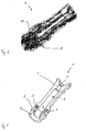
- the splitting of the LOX mass flow at the first outlet opening 6 can be better seen from Fig.2.
- the media streams resulting from the device 9 for splitting the LOX mass flow are designated by the reference numeral 14, while the media flow emerging through the second outlet opening in the form of the annular gap 7 is designated by the reference numeral 15.
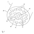
- FIG 3 shows an enlarged perspective view of another embodiment of the plate 10 shown in Figure 1.
- This example on an inner annulus 16 and an outer annulus 17 each have a plurality of further holes 12 which surround the centrally disposed bore 11 ,
- the circular rings 16, 17 are arranged concentrically to the centrally disposed bore 11.
- the further holes 12 are arranged on circular rings. Rather, the arrangement of the further holes 12 and the centrally disposed bore 11 arbitrarily over the base of the plate 10, if the desired effect of the splitting of the mass flow is achieved.
- An improvement of the mixing process of the fuel components results from an additional inclination of at least some of the further bores 12 with respect to the axis of the injection element, which coincides with the axis of the central bore 11.
- the inclination of the further bores 12, e.g. are arranged on the inner circular line 16 of the plate 10 of Figure 3, it can be done to the outside, as can be clearly seen in Figure 4, with respect to the axis 18 of the inner element.
- the axes of the further holes 12 are provided with the reference numeral 19 and close to the axis 18 only for the purpose of illustration in each case an equal angle 20 a.
- the axes 19 of the further holes 12 are arranged inclined in the circumferential direction (i.e., into or out of the sheet plane), whereby a swirl of the medium injected into the combustion chamber can be generated.
- the mixing fluctuation ratio can be influenced.
- the injection element according to the invention is particularly suitable for the use of cryogenic fuels (oxygen and hydrogen). While maintaining the coaxial injection principle, an increased, intensified mixing of the fuel components can be effected. At the same time an enlarged contact surface of the fuel components is created, whereby a high efficiency is ensured.
- the degree of mixing as well as the extent of the enlarged contact surface can be influenced by varying the number and size of the holes in the plate in the first outlet opening. Other factors influencing these parameters include the possibility of inclining the holes in relation to the axis of the inner element and the holes on different circular lines to each other. As a result, multiple oxygen jets are thereby formed at the outlet port of the centrally located inner member. As a result, a substantial increase in the element-specific mass flow rate is possible.
Landscapes
- Engineering & Computer Science (AREA)
- Chemical & Material Sciences (AREA)
- Combustion & Propulsion (AREA)
- Mechanical Engineering (AREA)
- General Engineering & Computer Science (AREA)
- Fuel-Injection Apparatus (AREA)
- Electrical Control Of Air Or Fuel Supplied To Internal-Combustion Engine (AREA)
- Compositions Of Oxide Ceramics (AREA)
Abstract
Description
- Die Erfindung betrifft ein Einspritzelement, insbesondere für einen Raketenantrieb, mit einem inneren Element mit einer ersten Auslassöffnung und einem koaxial dazu angeordneten äußeren Element mit mindestens einer zur ersten Auslassöffnung koaxial angeordneten zweiten Auslassöffnung zum Aufnehmen und Einspritzen von Treibstoff in einen Brennraum.
- Einspritzelemente in einem Raketenantrieb dienen der Gemischaufbereitung und der Gewährleistung einer optimalen Verbrennung in dem Brennraum des Raketenantriebs. Die Hauptaufgabe der Einspritzelemente liegt in der optimalen Gemischaufbereitung zur Erzielung eines höchstmöglichen Verbrennungswirkungsgrades. Dies wird in erster Linie durch eine möglichst feine Zerstäubung des Treibstoffes erreicht. Hierbei spielt die Anzahl der Einspritzelemente in dem Raketenantrieb eine entscheidende Rolle.
- Im Bereich so genannter kryogener Triebwerke (LOX-LH2) werden hierfür koaxiale Einspritzelemente verwendet. Ein aus dem Stand der Technik bekanntes Einspritzelement 1 ist exemplarisch in Fig.5 dargestellt. Die Einspritzung des flüssigen Sauerstoffs in die Brennkammer erfolgt über eine Auslassöffnung 6 des inneren Elements 2, das auch als "LOX-Post" bezeichnet wird, während der Wasserstoff über einen das innere Element 2 umgebenden, Ringspalt 7, das koaxial angeordnete äußere Element 3, zugeführt wird.
- Durch das Vorsehen einer dem inneren Element 2 zugeordneten Blende 4 erfolgt die Entkopplung zwischen einem Fördersystem der Treibstoffkomponente Sauerstoff und der Brennkammer. Die Entkopplung zwischen dem Fördersystem des Wasserstoffs und der Brennkammer wird durch Elementeintrittsbohrungen 8 an dem äußeren Element 3 übernommen, welche auch gleichzeitig eine Filterfunktion innehaben.
- Die Gemischaufbereitung und somit auch der Ausbrenngrad des Treibstoffes wird in entscheidendem Maße vom Impulsverhältnis als auch von der Größe der Kontaktoberfläche der Treibstoffkomponenten und damit wiederum von der Anzahl der Einspritzelemente bestimmt. Raketentriebwerke weisen deshalb eine große Anzahl derartiger Einspritzelemente auf.
- Zur Schaffung eines kostengünstigeren Raketentriebwerks wäre es jedoch günstig, die Anzahl der Einspritzelemente reduzieren zu können, wobei gleichzeitig das Niveau des Ausbrenngrades beibehalten werden kann.
- Durch die Verwendung von Drallelementen oder die starke Deformation der ersten Auslassöffnung des inneren Elements ergibt sich eine verstärkte Interaktion zwischen den Treibstoffkomponenten. Als weitere Möglichkeit ist die Verwendung von so genannten Tri-Koaxial-Einspritzelementen bekannt, bei denen die Durchmischung der Treibstoffkomponenten auf der Vergrößerung der Interaktionsoberfläche zwischen den Treibstoffkomponenten beruht. Die Verwendung derartiger Einspritzelemente ermöglichen zwar die Anzahl der Einspritzelemente in einem Raketentriebwerk zu verringern, führt jedoch andererseits aufgrund der aufwendigeren Konstruktionen der Einspritzelemente zu höheren Gesamtkosten des Raketentriebwerks.
- Es ist daher Aufgabe der vorliegenden Erfindung, ein Einspritzelement, insbesondere für einen Raketenantrieb, anzugeben, welches bei einfachen konstruktiven Aufbau und damit günstigen Herstellungskosten ein hohes Niveau des Ausbrenngrades bereitstellt.
- Diese Aufgabe wird durch ein Einspritzelement mit den Merkmalen des Patentanspruches 1 gelöst. Bevorzugte Ausgestaltungen der Erfindung ergeben sich aus den abhängigen Patentansprüchen.
- Der Erfindung liegt die Erkenntnis zugrunde, dass eine besonders intensive Durchmischung der Treibstoffkomponenten durch eine Vergrößerung der Kontaktoberfläche der miteinander zu vermischenden Treibstoffkomponenten erzielt werden kann.
- Das erfindungsgemäße Einspritzelement zeichnet sich deshalb dadurch aus, dass die erste Auslassöffnung des inneren Elements mit einer Einrichtung zur Aufspaltung einer Treibstoffkomponente in zumindest zwei Medienströme versehen ist. Durch die Aufspaltung des durch die erste Auslassöffnung des inneren Elements ausströmenden Treibstoffkomponente kann die gewünschte Vergrößerung der Kontaktoberfläche auf einfache Weise realisiert werden. Die dadurch erzielte intensive Mischung der Treibstoffkomponenten bewirkt das gewünschte hohe Niveau des Ausbrenngrades.
- In einer Ausgestaltung des erfindungsgemäßen Einspritzelements ist die Einrichtung zur Aufspaltung des durch die erste Auslassöffnung strömenden Mediums durch eine die erste Auslassöffnung verschließende Platte mit zumindest zwei Bohrungen gebildet. Der Begriff der Bohrung soll hierbei keine Aussage hinsichtlich dessen Gestalt beinhalten. Die Bohrung kann beispielsweise kreisrund sein, jedoch auch eine beliebige andere Querschnittsform aufweisen. Durch das Vorsehen der die erste Auslassöffnung verschließenden Platte mit zumindest zwei Bohrungen wird die zwangsweise Aufspaltung des durch die erste Auslassöffnung strömenden Mediums bewirkt. Durch diese Aufspaltung in eine der Anzahl der Bohrungen entsprechende Anzahl an Strahlen erfolgt die Vergrößerung der Gesamtoberfläche des Mediums und somit eine Zunahme der Kontaktoberfläche der zu mischenden Treibstoffkomponenten.
- In einer weiteren Ausführungsform ist vorgesehen, dass die Platte eine zentral angeordnete Bohrung aufweist, die von einer Mehrzahl an weiteren Bohrungen in der Platte umgeben ist. In einer weiteren Ausführungsform sind die Achsen zumindest mancher der weiteren Bohrungen in bezug auf die Achse des inneren Elements geneigt. In einer weiteren Ausführungsform ist vorgesehen, dass die Achsen zumindest mancher der weiteren Bohrungen in bezug auf die Achse des inneren Elements in Strömungsrichtung des Mediums nach außen geneigt sind. Die Wahl der Anzahl, der Größe und der Anordnung der weiteren Bohrungen in der die erste Auslassöffnung verschließenden Platte sowie die Wahl des Winkels der Achse zumindest mancher der weiteren Bohrungen in bezug auf die Achse des inneren Elements können im Rahmen von Optimierungsprozessen gewählt werden. Als zu optimierender Parameter ist hierbei u.a. die Durchmischung der Treibstoffkomponenten zu berücksichtigen.
- In einer weiteren Ausführungsform sind die Mehrzahl an weiteren Bohrungen auf zumindest einer konzentrisch zu der zentralen Bohrung liegenden Kreislinie angeordnet. Dabei kann es zweckmäßig sein, wenn die Achsen der weiteren Bohrungen auf einer gemeinsamen Kreislinie in bezug auf die Achse des inneren Elements den gleichen Winkel aufweisen.
- Eine weitere zweckmäßige Ausgestaltung sieht vor, dass die Achsen der weiteren Bohrungen auf unterschiedlichen Kennlinien in bezug auf die Achse des inneren Elements einen unterschiedlichen Winkel aufweisen. Dabei ist es besonders vorteilhaft, wenn der Winkel der Achsen der weiteren Bohrungen in bezug auf die Achse des inneren Elements mit zunehmendem Radius der Kreislinien zunimmt. Der maximale Winkel sollte insbesondere für die weiteren Bohrungen auf der Kreislinie mit dem größten Radius, das heißt im wandnahen Bereich, derart gewählt werden, dass starke Mischungsverhältnisschwankungen vermieden sind. Dies wäre dann gegeben, wenn die durch die weiteren Bohrungen ausgestoßenen Mediumstrahlen die andere Treibstoffkomponente durchschlagen.
- Wenn die Achsen, wie dies gemäß einer weiteren Ausführungsform vorgesehen ist, zumindest mancher der weiteren Bohrungen in Umfangsrichtung geneigt angeordnet sind, lässt sich ein gewisser Drall erzeugen, wodurch eine weitere Verbesserung der Durchmischung erzielt wird. Der Neigungswinkel in Umfangsrichtung kann dabei unterschiedlich von dem Neigungswinkel in bezug auf die Achse des inneren Elements ausgebildet sein. Das Maß der Neigung nach außen und/oder in Umfangsrichtung ist eine Optimierungsfrage, die durch einen Fachmann mit Hilfe von Simulationen oder Versuchen gelöst werden kann.
- Eine weitere Ausgestaltung sieht vor, dass das innere Element an dem der Einrichtung zur Aufspaltung des durch die erste Auslassöffnung strömenden Mediums zugewandten Ende kegelstumpfförmig ausgebildet ist. Dabei erweitert sich das innere Element bevorzugt in Richtung der ersten Auslassöffnung.
- Die Erfindung betrifft ferner die Verwendung eines Einspritzelementes in einem Raketentriebwerk, das einen Brennraum aufweist. Das Raketentriebwerk zeichnet sich dadurch aus, dass es mindestens ein Einspritzelement gemäß der Erfindung umfasst.
- Weitere Vorteile und Anwendungsmöglichkeiten der vorliegenden Erfindung ergeben sich aus der nachfolgenden Beschreibung in Verbindung mit den in den Zeichnungen dargestellten Ausführungsbeispielen. Es zeigen:
- Fig. 1
- ein Ausführungsbeispiel eines erfindungsgemäßen Einspritzelements in einer geschnittenen perspektivischen Darstellung,
- Fig. 2
- das in Fig.1 gezeigte Einspritzelement, wobei die Aufspaltung in mehrere Medienströme ersichtlich ist,
- Fig. 3
- eine vergrößerte perspektivische Darstellung der Einrichtung zur Aufspaltung der durch ein inneres Element des Einspritzelementes ausgestoßenen Treibstoffkomponente,
- Fig. 4
- einen Querschnitt durch eine erfindungsgemäße Einrichtung zur Aufspaltung der Treibstoffkomponente, und
- Fig. 5
- ein aus dem Stand der Technik bekanntes Einspritzelement.
- Fig.1 zeigt ein erfindungsgemäßes kryogenes Einspritzelement 1 in einer perspektivischen geschnittenen Darstellung. Das Einspritzelement 1 weist im Wesentlichen das für kryogene Treibstoffe bekannte Aufbauprinzip von Koaxialelementen auf. Die Zuführung des flüssigen Sauerstoffs in den Brennraum (nicht dargestellt) erfolgt über ein zentrales inneres Element 2 mit einer ersten Auslassöffnung 6, während die Zuführung des Wasserstoffs zum Brennraum über ein äußeres Element 3 erfolgt, welches das innere Element 2 koaxial umgibt. Dadurch wird eine zweite Auslassöffnung 7 in Form eines Ringspalts bereitgestellt.
- Das innere Element 2 weist eine aus dem Stand der Technik prinzipiell bereits bekannte Blende 4 zur Entkopplung zwischen einem (nicht dargestellten) Fördersystem und der (ebenfalls nicht dargestellten) Brennkammer auf. Die Blende 4 ist in bekannter Weise mit einer ersten Elementeintrittsbohrung 5 versehen. Zur Entkopplung des Fördersystems und der Brennkammer auf der Wasserstoff-Seite weist das äußere Element 3 in ebenfalls bekannter Weise zweite Elementeintrittsbohrungen 8 auf, welche gleichzeitig eine Filterfunktion übernehmen.
- Die erste Auslassöffnung 6 ist erfindungsgemäß mit einer Platte 10 versehen, welche in der Fig.1 mit einer zentralen, lediglich beispielhaft kreisförmigen, Bohrung 11 und einer Mehrzahl an weiteren, die zentrale Bohrung 11 auf einer Kreislinie umgebenden Bohrungen 12 versehen ist. Hierdurch ist eine Einrichtung 9 zur Aufspaltung einer Treibstoffkomponente (in diesem Fall Sauerstoff) gebildet. Die weiteren Bohrungen 12 weisen ebenfalls lediglich beispielhaft einen kreisförmigen Querschnitt auf. Durch die mit einer Mehrzahl an Bohrungen 11, 12 versehene Platte 10 wird eine zwangsweise Aufspaltung des Sauerstoffstroms mit Durchströmen der ersten Auslassöffnung 6 bewirkt. Hierdurch wird eine verstärkte Durchmischung der Treibstoffkomponenten erzielt, wodurch auch bei größeren Elementmassendurchsätzen durch das Einspritzelement 1 eine Abnahme des Wirkungsgrad-Niveaus vermieden werden kann. Durch die Aufspaltung des LOX-Medienstroms in einer der Anzahl der Bohrungen 11, 12 entsprechenden Anzahl an "Strahlen" erfolgt eine Vergrößerung der Gesamtoberfläche des Oxidators und damit eine Zunahme der Kontaktoberfläche der Treibstoffkomponenten.
- Die Aufspaltung des LOX-Massenstroms an der ersten Auslassöffnung 6 kann besser aus Fig.2 ersehen werden. In dieser sind die durch die Einrichtung 9 zur Aufspaltung des LOX-Massenstroms entstehenden Medienströme mit dem Bezugszeichen 14 gekennzeichnet, während der durch die zweite Auslassöffnung in Form des Ringspalts 7 austretenden Medienstrom mit dem Bezugszeichen 15 versehen ist.
- Fig.3 zeigt in einer vergrößerten perspektivischen Darstellung ein weiteres Ausführungsbeispiel der in Fig.1 dargestellten Platte 10. Diese weist beispielhaft auf einem inneren Kreisring 16 und einem äußeren Kreisring 17 jeweils eine Mehrzahl an weiteren Bohrungen 12 auf, die die zentral angeordnete Bohrung 11 umgeben. Die Kreisringe 16, 17 sind dabei konzentrisch zu der zentral angeordneten Bohrung 11 angeordnet.
- Entgegen der zeichnerischen Darstellung ist es ebenfalls nicht notwendig, dass die weiteren Bohrungen 12 auf Kreisringen angeordnet sind. Vielmehr kann die Anordnung der weiteren Bohrungen 12 sowie der zentral angeordneten Bohrung 11 beliebig über die Grundfläche der Platte 10 erfolgen, wenn die gewünschte Wirkung der Aufspaltung des Massenstroms erzielt wird.
- Eine Verbesserung des Mischungsprozesses der Treibstoffkomponenten ergibt sich durch eine zusätzliche Neigung zumindest mancher der weiteren Bohrungen 12 in Bezug auf die Achse des Einspritzelementes, welche mit der Achse der Zentralbohrung 11 übereinstimmt. Die Neigung der weiteren Bohrungen 12, die z.B. auf der inneren Kreislinie 16 der Platte 10 aus Fig.3 angeordnet sind, kann dabei nach außen, wie dies aus Fig.4 gut ersichtlich ist, in Bezug auf die Achse 18 des inneren Elements erfolgen. Die Achsen der weiteren Bohrungen 12 sind mit dem Bezugszeichen 19 versehen und schließen mit der Achse 18 lediglich zum Zwecke der Illustration jeweils einen gleichen Winkel 20 ein. Zusätzlich oder alternativ kann vorgesehen sein, dass die Achsen 19 der weiteren Bohrungen 12 in Umfangsrichtung (d.h. in die Blattebene hinein oder aus dieser heraus) geneigt angeordnet sind, wodurch sich ein Drall des in die Brennkammer eingespritzten Mediums erzeugen lässt. Das Vorsehen einer Neigung in Bezug auf die Achse des inneren Elements 18 und/oder in Umfangsrichtung einer der Kreislinien 16, 17 erlaubt bei Beibehaltung des einfachen Konstruktionsprinzips von koaxialen Einspritzelementen und gleichzeitiger Erhöhung des Elementdurchsatzes die Erzielung eines hohen Wirkungsgradniveaus.
- Durch die Variation der Anzahl der Bohrungen, deren Neigung gegenüber der Achse des inneren Elements und/oder in Umfangsrichtung, insbesondere auf der äußersten Kreislinie 17, kann zusätzlich das Mischungsschwankungsverhältnis beeinflusst werden.
- Das erfindungsgemäße Einspritzelement eignet sich insbesondere für die Verwendung kryogener Treibstoffe (Sauerstoff und Wasserstoff). Bei gleichzeitiger Beibehaltung des koaxialen Einspritzprinzips kann eine erhöhte, intensivierte Durchmischung der Treibstoffkomponenten bewirkt werden. Gleichzeitig wird eine vergrößerte Kontaktoberfläche der Treibstoffkomponenten geschaffen, wodurch ein hoher Wirkungsgrad gewährleistet ist. Der Grad der Durchmischung sowie das Maß der vergrößerten Kontaktoberfläche kann durch Variation der Anzahl und der Größe der Bohrungen in der Platte in der ersten Auslassöffnung beeinflusst werden. Weitere Faktoren zur Beeinflussung dieser Parameter ist die Möglichkeit der Neigung der Bohrungen in Bezug auf die Achse des inneren Elements und der Bohrungen auf unterschiedlichen Kreislinien zueinander. Im Ergebnis werden dadurch multiple Sauerstoffstrahlen an der Auslassöffnung des zentral angeordneten inneren Elements ausgebildet. Dadurch ist eine wesentliche Steigerung des elementspezifischen Massendurchsatzes möglich.
-
- 1
- Einspritzelement
- 2
- inneres Element
- 3
- äußeres Element
- 4
- Blende
- 5
- erste Elementeintrittsbohrung
- 6
- erste Auslassöffnung
- 7
- zweite Auslassöffnung in Form eines Ringspalts
- 8
- zweite Elementeintrittsbohrung
- 9
- Einrichtung zur Aufspaltung in zumindest zwei Medienströme
- 10
- Platte
- 11
- zentrale Bohrung
- 12
- weitere Bohrung
- 13
- der ersten Auslassöffnung zugewandtes Ende des inneren Elements
- 14
- Medienstrom
- 15
- Medienstrom
- 16
- Kreislinie
- 17
- Kreislinie
- 18
- Achse des inneren Elements
- 19
- Achse der weiteren Bohrung 12
- 20
- Winkel zwischen Achse 18 des inneren Elements und Achse 19 der weiteren Bohrung
Claims (13)
- Einspritzelement (1), insbesondere für einen Raketenantrieb, mit einem inneren Element (2) mit einer ersten Auslassöffnung und einem koaxial dazu angeordneten äußeren Element (3) mit mindestens einer zur ersten Auslassöffnung koaxial angeordneten zweiten Auslassöffnung zum Aufnehmen und Einspritzen von Treibstoff in einen Brennraum, dadurch gekennzeichnet, dass die erste Auslassöffnung des inneren Elements (2) mit einer Einrichtung (9) zur Aufspaltung einer Treibstoffkomponente in zumindest zwei Medienströme versehen ist.
- Einspritzelement nach Anspruch 1, dadurch gekennzeichnet, dass die Einrichtung (9) zur Aufspaltung des durch die erste Auslassöffnung strömenden Mediums durch eine die erste Auslassöffnung (6) verschließende Platte (10) mit zumindest zwei Bohrungen (11,12) gebildet ist.
- Einspritzelement nach Anspruch 2, dadurch gekennzeichnet, dass die Platte (10) eine zentral angeordnete Bohrung (11) aufweist, die von einer Mehrzahl an weiteren Bohrungen (12) in der Platte (10) umgeben ist.
- Einspritzelement nach Anspruch 3, dadurch gekennzeichnet, dass die Achsen zumindest mancher der weiteren Bohrungen (12) in Bezug auf die Achse des inneren Elements (2) geneigt sind.
- Einspritzelement nach Anspruch 4, dadurch gekennzeichnet, dass die Achsen zumindest mancher der weiteren Bohrungen (12) in Bezug auf die Achse des inneren Elements (2) in Strömungsrichtung eines Betriebsmittels nach außen geneigt sind.
- Einspritzelement nach einem der Ansprüche 2 bis 5, dadurch gekennzeichnet, dass die Mehrzahl an weiteren Bohrungen (12) auf einer konzentrisch zu der zentralen Bohrung (11) liegenden Kreislinie angeordnet sind.
- Einspritzelement nach Anspruch 6, dadurch gekennzeichnet, dass die Achsen der weiteren Bohrungen (12) auf einer gemeinsamen Kreislinie in Bezug auf die Achse des inneren Elements (2) den gleichen Winkel aufweisen.
- Einspritzelement nach Anspruch 6 oder 7, dadurch gekennzeichnet, dass die Achsen der weiteren Bohrungen (12) auf unterschiedlichen Kreislinien in Bezug auf die Achse des inneren Elements (2) einen unterschiedlichen Winkel aufweisen.
- Einspritzelement nach einem der Ansprüche 6 bis 8, dadurch gekennzeichnet, dass der Winkel der Achsen der weiteren Bohrungen (12) in Bezug auf die Achse des inneren Elements (2) mit zunehmenden Radius der Kreislinien zunimmt.
- Einspritzelement nach einem Ansprüche 2 bis 9, dadurch gekennzeichnet, dass die Achsen zumindest mancher der weiteren Bohrungen (12) in Umfangsrichtung geneigt angeordnet sind.
- Einspritzelement nach einem der vorherigen Ansprüche, dadurch gekennzeichnet, dass das innere Element (2) an dem der Einrichtung (9) zur Aufspaltung des durch die erste Auslassöffnung (6) strömenden Mediums zugewandten Ende (13) kegelstumpfförmig ausgebildet ist.
- Einspritzelement nach Anspruch 11, dadurch gekennzeichnet, dass sich das innere Element (2) in Richtung der ersten Auslassöffnung (6) erweitert.
- Verwendung eines Einspritzelements (1) nach einem der vorherigen Ansprüche in einem Raketentriebwert, das einen Brennraum aufweist.
Applications Claiming Priority (1)
| Application Number | Priority Date | Filing Date | Title |
|---|---|---|---|
| DE102005049686A DE102005049686B4 (de) | 2005-10-14 | 2005-10-14 | Einspritzelement |
Publications (2)
| Publication Number | Publication Date |
|---|---|
| EP1780395A1 true EP1780395A1 (de) | 2007-05-02 |
| EP1780395B1 EP1780395B1 (de) | 2008-12-03 |
Family
ID=37814258
Family Applications (1)
| Application Number | Title | Priority Date | Filing Date |
|---|---|---|---|
| EP06021226A Not-in-force EP1780395B1 (de) | 2005-10-14 | 2006-10-10 | Einspritzelement insbesondere für einen Raketenantrieb |
Country Status (3)
| Country | Link |
|---|---|
| EP (1) | EP1780395B1 (de) |
| AT (1) | ATE416305T1 (de) |
| DE (2) | DE102005049686B4 (de) |
Cited By (1)
| Publication number | Priority date | Publication date | Assignee | Title |
|---|---|---|---|---|
| DE102016209650A1 (de) | 2016-06-02 | 2017-12-07 | Airbus Ds Gmbh | Einspritzvorrichtung für ein raketentriebwerk |
Families Citing this family (1)
| Publication number | Priority date | Publication date | Assignee | Title |
|---|---|---|---|---|
| DE102008049842B4 (de) | 2008-10-01 | 2012-04-05 | Astrium Gmbh | Einspritzelement für eine Raketenbrennkammer und Einspritzsystem |
Citations (4)
| Publication number | Priority date | Publication date | Assignee | Title |
|---|---|---|---|---|
| US3136123A (en) * | 1959-08-20 | 1964-06-09 | Stein Samuel | Rocket engine injector |
| US3611722A (en) * | 1967-05-10 | 1971-10-12 | Us Air Force | Liquid fluorine injector design |
| US4801092A (en) * | 1986-02-24 | 1989-01-31 | Rockwell International Corporation | Injector assembly for a fluid fueled engine |
| EP0924424A2 (de) * | 1997-12-22 | 1999-06-23 | TRW Inc. | Koaxialer Injektor für drei flüssige Raketentreibstoffkomponenten |
Family Cites Families (4)
| Publication number | Priority date | Publication date | Assignee | Title |
|---|---|---|---|---|
| DE19651646C2 (de) * | 1996-12-12 | 2002-07-11 | Deutsch Zentr Luft & Raumfahrt | Verfahren zum Einblasen einer ersten und zweiten Brennstoffkomponente und Einblaskopf |
| JP4475837B2 (ja) * | 2001-03-13 | 2010-06-09 | 三菱重工業株式会社 | 液体ロケットエンジン用噴射器の同軸エレメント |
| US7849850B2 (en) * | 2003-02-28 | 2010-12-14 | Battelle Memorial Institute | Nozzle for handheld pulmonary aerosol delivery device |
| DE102004006665B4 (de) * | 2004-02-11 | 2007-06-21 | Eads Space Transportation Gmbh | Einspritzelement in Koaxialbauweise mit zwei Brennzonen |
-
2005
- 2005-10-14 DE DE102005049686A patent/DE102005049686B4/de not_active Expired - Fee Related
-
2006
- 2006-10-10 EP EP06021226A patent/EP1780395B1/de not_active Not-in-force
- 2006-10-10 DE DE502006002242T patent/DE502006002242D1/de active Active
- 2006-10-10 AT AT06021226T patent/ATE416305T1/de not_active IP Right Cessation
Patent Citations (4)
| Publication number | Priority date | Publication date | Assignee | Title |
|---|---|---|---|---|
| US3136123A (en) * | 1959-08-20 | 1964-06-09 | Stein Samuel | Rocket engine injector |
| US3611722A (en) * | 1967-05-10 | 1971-10-12 | Us Air Force | Liquid fluorine injector design |
| US4801092A (en) * | 1986-02-24 | 1989-01-31 | Rockwell International Corporation | Injector assembly for a fluid fueled engine |
| EP0924424A2 (de) * | 1997-12-22 | 1999-06-23 | TRW Inc. | Koaxialer Injektor für drei flüssige Raketentreibstoffkomponenten |
Cited By (3)
| Publication number | Priority date | Publication date | Assignee | Title |
|---|---|---|---|---|
| DE102016209650A1 (de) | 2016-06-02 | 2017-12-07 | Airbus Ds Gmbh | Einspritzvorrichtung für ein raketentriebwerk |
| DE102016209650B4 (de) | 2016-06-02 | 2019-03-14 | Arianegroup Gmbh | Einspritzvorrichtung für ein raketentriebwerk |
| US11111882B2 (en) | 2016-06-02 | 2021-09-07 | Arianegroup Gmbh | Injection apparatus for a rocket engine |
Also Published As
| Publication number | Publication date |
|---|---|
| DE102005049686B4 (de) | 2008-10-30 |
| ATE416305T1 (de) | 2008-12-15 |
| DE502006002242D1 (de) | 2009-01-15 |
| EP1780395B1 (de) | 2008-12-03 |
| DE102005049686A1 (de) | 2007-04-19 |
Similar Documents
| Publication | Publication Date | Title |
|---|---|---|
| DE10044624B4 (de) | Koaxial-Einspritzdüse | |
| EP2699791B1 (de) | Brennkraftmaschine | |
| EP0619457B1 (de) | Vormischbrenner | |
| DE10303858B4 (de) | Kraftstoff-Einspritzdüsenbaugruppe mit induzierten Turbulenzen | |
| DE69308518T2 (de) | Injektor mit einer porösen Wand für eine Raketenbrennkammer | |
| DE19827219A1 (de) | Kraftstoffeinspritzventil für einen Verbrennungsmotor | |
| EP0740063A1 (de) | Einspritzelement in Koaxialbauweise für Raketenbrennkammern | |
| EP0988449B1 (de) | Brennstoffeinspritzvorrichtung | |
| DE69101869T2 (de) | Zerstäuber für zähflüssige Brennstoffe. | |
| EP1999409A1 (de) | Brenneranordnung | |
| DE10130355C2 (de) | Einspritzelement für einen Raketenantrieb | |
| DE69618914T2 (de) | Brennstoff-Einspritzvorrichtung und -verfahren | |
| EP1780395B1 (de) | Einspritzelement insbesondere für einen Raketenantrieb | |
| DE102016224084B4 (de) | Kraftstoffinjektor | |
| DE102004006665B4 (de) | Einspritzelement in Koaxialbauweise mit zwei Brennzonen | |
| DE10351715B4 (de) | Einspritzkopf für ein Flüssigkeitsraketentriebwerk | |
| EP2898214B1 (de) | Kraftstoff-einspritzsystem einer brennkraftmaschine | |
| DE10354467A1 (de) | Brennstoffeinspritzventil | |
| EP3804861A1 (de) | Injektionsdüse für eine sprühvorrichtung und sprühvorrichtung | |
| WO2019030049A1 (de) | Injektor für gasförmige kraftstoffe | |
| WO2012084515A1 (de) | Düsenkörper mit einem einspritzloch mit mindestens zwei eintrittsöffnungen | |
| DE102006032429A1 (de) | Kraftstoffeinspritzvorrichtung für eine Fluggasturbine | |
| WO2003104640A1 (de) | Injektor zum einspritzen von kraftstoff | |
| DE102012101682A1 (de) | Injektor für einen Einspritzkopf einer Brennkammer | |
| EP1565650B1 (de) | Einspritzvorrichtung zum einspritzen von kraftstoff |
Legal Events
| Date | Code | Title | Description |
|---|---|---|---|
| PUAI | Public reference made under article 153(3) epc to a published international application that has entered the european phase |
Free format text: ORIGINAL CODE: 0009012 |
|
| AK | Designated contracting states |
Kind code of ref document: A1 Designated state(s): AT BE BG CH CY CZ DE DK EE ES FI FR GB GR HU IE IS IT LI LT LU LV MC NL PL PT RO SE SI SK TR |
|
| AX | Request for extension of the european patent |
Extension state: AL BA HR MK YU |
|
| 17P | Request for examination filed |
Effective date: 20070704 |
|
| 17Q | First examination report despatched |
Effective date: 20070903 |
|
| AKX | Designation fees paid |
Designated state(s): AT BE BG CH CY CZ DE DK EE ES FI FR GB GR HU IE IS IT LI LT LU LV MC NL PL PT RO SE SI SK TR |
|
| GRAP | Despatch of communication of intention to grant a patent |
Free format text: ORIGINAL CODE: EPIDOSNIGR1 |
|
| GRAS | Grant fee paid |
Free format text: ORIGINAL CODE: EPIDOSNIGR3 |
|
| GRAA | (expected) grant |
Free format text: ORIGINAL CODE: 0009210 |
|
| GRAL | Information related to payment of fee for publishing/printing deleted |
Free format text: ORIGINAL CODE: EPIDOSDIGR3 |
|
| GRAS | Grant fee paid |
Free format text: ORIGINAL CODE: EPIDOSNIGR3 |
|
| AK | Designated contracting states |
Kind code of ref document: B1 Designated state(s): AT BE BG CH CY CZ DE DK EE ES FI FR GB GR HU IE IS IT LI LT LU LV MC NL PL PT RO SE SI SK TR |
|
| REG | Reference to a national code |
Ref country code: GB Ref legal event code: FG4D Free format text: NOT ENGLISH |
|
| REG | Reference to a national code |
Ref country code: CH Ref legal event code: EP |
|
| REG | Reference to a national code |
Ref country code: IE Ref legal event code: FG4D Free format text: LANGUAGE OF EP DOCUMENT: GERMAN |
|
| REF | Corresponds to: |
Ref document number: 502006002242 Country of ref document: DE Date of ref document: 20090115 Kind code of ref document: P |
|
| PG25 | Lapsed in a contracting state [announced via postgrant information from national office to epo] |
Ref country code: LT Free format text: LAPSE BECAUSE OF FAILURE TO SUBMIT A TRANSLATION OF THE DESCRIPTION OR TO PAY THE FEE WITHIN THE PRESCRIBED TIME-LIMIT Effective date: 20081203 Ref country code: ES Free format text: LAPSE BECAUSE OF FAILURE TO SUBMIT A TRANSLATION OF THE DESCRIPTION OR TO PAY THE FEE WITHIN THE PRESCRIBED TIME-LIMIT Effective date: 20090314 |
|
| NLV1 | Nl: lapsed or annulled due to failure to fulfill the requirements of art. 29p and 29m of the patents act | ||
| PG25 | Lapsed in a contracting state [announced via postgrant information from national office to epo] |
Ref country code: PL Free format text: LAPSE BECAUSE OF FAILURE TO SUBMIT A TRANSLATION OF THE DESCRIPTION OR TO PAY THE FEE WITHIN THE PRESCRIBED TIME-LIMIT Effective date: 20081203 Ref country code: NL Free format text: LAPSE BECAUSE OF FAILURE TO SUBMIT A TRANSLATION OF THE DESCRIPTION OR TO PAY THE FEE WITHIN THE PRESCRIBED TIME-LIMIT Effective date: 20081203 Ref country code: SI Free format text: LAPSE BECAUSE OF FAILURE TO SUBMIT A TRANSLATION OF THE DESCRIPTION OR TO PAY THE FEE WITHIN THE PRESCRIBED TIME-LIMIT Effective date: 20081203 Ref country code: LV Free format text: LAPSE BECAUSE OF FAILURE TO SUBMIT A TRANSLATION OF THE DESCRIPTION OR TO PAY THE FEE WITHIN THE PRESCRIBED TIME-LIMIT Effective date: 20081203 Ref country code: FI Free format text: LAPSE BECAUSE OF FAILURE TO SUBMIT A TRANSLATION OF THE DESCRIPTION OR TO PAY THE FEE WITHIN THE PRESCRIBED TIME-LIMIT Effective date: 20081203 |
|
| REG | Reference to a national code |
Ref country code: IE Ref legal event code: FD4D |
|
| PG25 | Lapsed in a contracting state [announced via postgrant information from national office to epo] |
Ref country code: BG Free format text: LAPSE BECAUSE OF FAILURE TO SUBMIT A TRANSLATION OF THE DESCRIPTION OR TO PAY THE FEE WITHIN THE PRESCRIBED TIME-LIMIT Effective date: 20090303 Ref country code: RO Free format text: LAPSE BECAUSE OF FAILURE TO SUBMIT A TRANSLATION OF THE DESCRIPTION OR TO PAY THE FEE WITHIN THE PRESCRIBED TIME-LIMIT Effective date: 20081203 Ref country code: EE Free format text: LAPSE BECAUSE OF FAILURE TO SUBMIT A TRANSLATION OF THE DESCRIPTION OR TO PAY THE FEE WITHIN THE PRESCRIBED TIME-LIMIT Effective date: 20081203 Ref country code: IE Free format text: LAPSE BECAUSE OF FAILURE TO SUBMIT A TRANSLATION OF THE DESCRIPTION OR TO PAY THE FEE WITHIN THE PRESCRIBED TIME-LIMIT Effective date: 20081203 |
|
| PG25 | Lapsed in a contracting state [announced via postgrant information from national office to epo] |
Ref country code: IS Free format text: LAPSE BECAUSE OF FAILURE TO SUBMIT A TRANSLATION OF THE DESCRIPTION OR TO PAY THE FEE WITHIN THE PRESCRIBED TIME-LIMIT Effective date: 20090403 Ref country code: SE Free format text: LAPSE BECAUSE OF FAILURE TO SUBMIT A TRANSLATION OF THE DESCRIPTION OR TO PAY THE FEE WITHIN THE PRESCRIBED TIME-LIMIT Effective date: 20090303 Ref country code: PT Free format text: LAPSE BECAUSE OF FAILURE TO SUBMIT A TRANSLATION OF THE DESCRIPTION OR TO PAY THE FEE WITHIN THE PRESCRIBED TIME-LIMIT Effective date: 20090504 Ref country code: CZ Free format text: LAPSE BECAUSE OF FAILURE TO SUBMIT A TRANSLATION OF THE DESCRIPTION OR TO PAY THE FEE WITHIN THE PRESCRIBED TIME-LIMIT Effective date: 20081203 |
|
| PG25 | Lapsed in a contracting state [announced via postgrant information from national office to epo] |
Ref country code: SK Free format text: LAPSE BECAUSE OF FAILURE TO SUBMIT A TRANSLATION OF THE DESCRIPTION OR TO PAY THE FEE WITHIN THE PRESCRIBED TIME-LIMIT Effective date: 20081203 |
|
| PLBE | No opposition filed within time limit |
Free format text: ORIGINAL CODE: 0009261 |
|
| STAA | Information on the status of an ep patent application or granted ep patent |
Free format text: STATUS: NO OPPOSITION FILED WITHIN TIME LIMIT |
|
| PG25 | Lapsed in a contracting state [announced via postgrant information from national office to epo] |
Ref country code: DK Free format text: LAPSE BECAUSE OF FAILURE TO SUBMIT A TRANSLATION OF THE DESCRIPTION OR TO PAY THE FEE WITHIN THE PRESCRIBED TIME-LIMIT Effective date: 20081203 |
|
| 26N | No opposition filed |
Effective date: 20090904 |
|
| BERE | Be: lapsed |
Owner name: ASTRIUM G.M.B.H. Effective date: 20091031 |
|
| PG25 | Lapsed in a contracting state [announced via postgrant information from national office to epo] |
Ref country code: MC Free format text: LAPSE BECAUSE OF NON-PAYMENT OF DUE FEES Effective date: 20091031 |
|
| PG25 | Lapsed in a contracting state [announced via postgrant information from national office to epo] |
Ref country code: GR Free format text: LAPSE BECAUSE OF FAILURE TO SUBMIT A TRANSLATION OF THE DESCRIPTION OR TO PAY THE FEE WITHIN THE PRESCRIBED TIME-LIMIT Effective date: 20090304 Ref country code: BE Free format text: LAPSE BECAUSE OF NON-PAYMENT OF DUE FEES Effective date: 20091031 |
|
| PG25 | Lapsed in a contracting state [announced via postgrant information from national office to epo] |
Ref country code: AT Free format text: LAPSE BECAUSE OF NON-PAYMENT OF DUE FEES Effective date: 20091010 |
|
| PG25 | Lapsed in a contracting state [announced via postgrant information from national office to epo] |
Ref country code: LU Free format text: LAPSE BECAUSE OF NON-PAYMENT OF DUE FEES Effective date: 20091010 |
|
| REG | Reference to a national code |
Ref country code: CH Ref legal event code: PL |
|
| GBPC | Gb: european patent ceased through non-payment of renewal fee |
Effective date: 20101010 |
|
| PG25 | Lapsed in a contracting state [announced via postgrant information from national office to epo] |
Ref country code: HU Free format text: LAPSE BECAUSE OF FAILURE TO SUBMIT A TRANSLATION OF THE DESCRIPTION OR TO PAY THE FEE WITHIN THE PRESCRIBED TIME-LIMIT Effective date: 20090604 |
|
| PG25 | Lapsed in a contracting state [announced via postgrant information from national office to epo] |
Ref country code: LI Free format text: LAPSE BECAUSE OF NON-PAYMENT OF DUE FEES Effective date: 20101031 Ref country code: CH Free format text: LAPSE BECAUSE OF NON-PAYMENT OF DUE FEES Effective date: 20101031 |
|
| PG25 | Lapsed in a contracting state [announced via postgrant information from national office to epo] |
Ref country code: GB Free format text: LAPSE BECAUSE OF NON-PAYMENT OF DUE FEES Effective date: 20101010 Ref country code: TR Free format text: LAPSE BECAUSE OF FAILURE TO SUBMIT A TRANSLATION OF THE DESCRIPTION OR TO PAY THE FEE WITHIN THE PRESCRIBED TIME-LIMIT Effective date: 20081203 |
|
| PG25 | Lapsed in a contracting state [announced via postgrant information from national office to epo] |
Ref country code: CY Free format text: LAPSE BECAUSE OF FAILURE TO SUBMIT A TRANSLATION OF THE DESCRIPTION OR TO PAY THE FEE WITHIN THE PRESCRIBED TIME-LIMIT Effective date: 20081203 |
|
| REG | Reference to a national code |
Ref country code: FR Ref legal event code: PLFP Year of fee payment: 10 |
|
| REG | Reference to a national code |
Ref country code: FR Ref legal event code: PLFP Year of fee payment: 11 |
|
| REG | Reference to a national code |
Ref country code: FR Ref legal event code: PLFP Year of fee payment: 12 |
|
| REG | Reference to a national code |
Ref country code: DE Ref legal event code: R081 Ref document number: 502006002242 Country of ref document: DE Owner name: ARIANEGROUP GMBH, DE Free format text: FORMER OWNER: ASTRIUM GMBH, 81667 MUENCHEN, DE |
|
| REG | Reference to a national code |
Ref country code: FR Ref legal event code: PLFP Year of fee payment: 13 |
|
| PGFP | Annual fee paid to national office [announced via postgrant information from national office to epo] |
Ref country code: FR Payment date: 20221028 Year of fee payment: 17 |
|
| PGFP | Annual fee paid to national office [announced via postgrant information from national office to epo] |
Ref country code: IT Payment date: 20221026 Year of fee payment: 17 Ref country code: DE Payment date: 20221019 Year of fee payment: 17 |
|
| REG | Reference to a national code |
Ref country code: DE Ref legal event code: R119 Ref document number: 502006002242 Country of ref document: DE |
|
| PG25 | Lapsed in a contracting state [announced via postgrant information from national office to epo] |
Ref country code: FR Free format text: LAPSE BECAUSE OF NON-PAYMENT OF DUE FEES Effective date: 20231031 Ref country code: DE Free format text: LAPSE BECAUSE OF NON-PAYMENT OF DUE FEES Effective date: 20240501 |
|
| PG25 | Lapsed in a contracting state [announced via postgrant information from national office to epo] |
Ref country code: IT Free format text: LAPSE BECAUSE OF NON-PAYMENT OF DUE FEES Effective date: 20231010 |
|
| PG25 | Lapsed in a contracting state [announced via postgrant information from national office to epo] |
Ref country code: IT Free format text: LAPSE BECAUSE OF NON-PAYMENT OF DUE FEES Effective date: 20231010 |