EP1780123A2 - Systems and methods for reducing surge loads in hose assemblies, including aircraft refueling hose assemblies - Google Patents
Systems and methods for reducing surge loads in hose assemblies, including aircraft refueling hose assemblies Download PDFInfo
- Publication number
- EP1780123A2 EP1780123A2 EP06076917A EP06076917A EP1780123A2 EP 1780123 A2 EP1780123 A2 EP 1780123A2 EP 06076917 A EP06076917 A EP 06076917A EP 06076917 A EP06076917 A EP 06076917A EP 1780123 A2 EP1780123 A2 EP 1780123A2
- Authority
- EP
- European Patent Office
- Prior art keywords
- surge
- fuel line
- hose
- aircraft
- loads
- Prior art date
- Legal status (The legal status is an assumption and is not a legal conclusion. Google has not performed a legal analysis and makes no representation as to the accuracy of the status listed.)
- Granted
Links
- 238000000034 method Methods 0.000 title claims abstract description 21
- 230000000712 assembly Effects 0.000 title claims abstract description 12
- 238000000429 assembly Methods 0.000 title claims abstract description 12
- 238000013016 damping Methods 0.000 claims abstract description 91
- 239000000446 fuel Substances 0.000 claims abstract description 59
- 239000000463 material Substances 0.000 claims abstract description 58
- 239000012530 fluid Substances 0.000 claims description 9
- 229920001971 elastomer Polymers 0.000 claims description 7
- 239000006260 foam Substances 0.000 claims description 6
- 239000006261 foam material Substances 0.000 claims description 4
- 229920001821 foam rubber Polymers 0.000 claims description 4
- 229920002379 silicone rubber Polymers 0.000 claims description 4
- 239000004945 silicone rubber Substances 0.000 claims description 4
- 239000007787 solid Substances 0.000 claims description 4
- 230000008901 benefit Effects 0.000 description 9
- 239000007789 gas Substances 0.000 description 8
- IJGRMHOSHXDMSA-UHFFFAOYSA-N Atomic nitrogen Chemical compound N#N IJGRMHOSHXDMSA-UHFFFAOYSA-N 0.000 description 6
- 230000001629 suppression Effects 0.000 description 6
- 230000003466 anti-cipated effect Effects 0.000 description 5
- 239000007788 liquid Substances 0.000 description 4
- 230000003247 decreasing effect Effects 0.000 description 3
- 229910052757 nitrogen Inorganic materials 0.000 description 3
- 238000009428 plumbing Methods 0.000 description 3
- 230000008859 change Effects 0.000 description 2
- 230000008569 process Effects 0.000 description 2
- 239000000523 sample Substances 0.000 description 2
- 238000012546 transfer Methods 0.000 description 2
- 239000012190 activator Substances 0.000 description 1
- 238000013459 approach Methods 0.000 description 1
- 238000004891 communication Methods 0.000 description 1
- 230000007246 mechanism Effects 0.000 description 1
- 238000012986 modification Methods 0.000 description 1
- 230000004048 modification Effects 0.000 description 1
- 239000003208 petroleum Substances 0.000 description 1
- 230000001681 protective effect Effects 0.000 description 1
Images


Classifications
-
- B—PERFORMING OPERATIONS; TRANSPORTING
- B64—AIRCRAFT; AVIATION; COSMONAUTICS
- B64D—EQUIPMENT FOR FITTING IN OR TO AIRCRAFT; FLIGHT SUITS; PARACHUTES; ARRANGEMENTS OR MOUNTING OF POWER PLANTS OR PROPULSION TRANSMISSIONS IN AIRCRAFT
- B64D39/00—Refuelling during flight
- B64D39/04—Adaptations of hose construction
-
- F—MECHANICAL ENGINEERING; LIGHTING; HEATING; WEAPONS; BLASTING
- F16—ENGINEERING ELEMENTS AND UNITS; GENERAL MEASURES FOR PRODUCING AND MAINTAINING EFFECTIVE FUNCTIONING OF MACHINES OR INSTALLATIONS; THERMAL INSULATION IN GENERAL
- F16L—PIPES; JOINTS OR FITTINGS FOR PIPES; SUPPORTS FOR PIPES, CABLES OR PROTECTIVE TUBING; MEANS FOR THERMAL INSULATION IN GENERAL
- F16L55/00—Devices or appurtenances for use in, or in connection with, pipes or pipe systems
- F16L55/02—Energy absorbers; Noise absorbers
- F16L55/027—Throttle passages
Definitions
- the present invention is directed generally toward reducing surge loads in hose assemblies, including reducing surge loads in hose assemblies used in systems for in-flight refueling of aircraft.
- In-flight refueling is an important method for extending the range of aircraft traveling long distances over areas having no feasible landing or refueling points.
- in-flight refueling is a relatively common operation, especially for military aircraft, the aircraft to be refueled (e.g., the receiver aircraft) must be precisely positioned relative to the tanker aircraft in order to provide safe engagement while the fuel is dispensed to the receiver aircraft.
- the requirement for precise relative spatial positioning of the two rapidly moving aircraft makes in-flight refueling a challenging operation.
- hose and drogue system which includes a refueling hose having a drogue disposed at one end.
- the hose and drogue are trailed behind the tanker aircraft once the tanker aircraft is on station. The pilot of the receiver aircraft then flies the receiver aircraft to intercept and couple with the drogue for refueling.
- boom refueling system typically includes a rigid boom extending from the tanker aircraft with a probe and nozzle at the distal end.
- the boom also includes airfoils controlled by a boom operator stationed on the refueling aircraft. The airfoils allow the boom operator to actively maneuver the boom with respect to the receiver aircraft, which flies in a fixed refueling position below and aft of the tanker aircraft.
- surge loads generated during the refueling process.
- high surge pressures can be generated in the refueling hose by any sudden or rapid changes in the flow rate of fuel passing through the refueling hose (e.g., starting or stopping the fuel flow, increasing or decreasing the fuel flow, etc.)
- the sudden changes in flow rate can in turn cause surge loads or surge pulses in the system, which can travel up the refueling hose and back into the tanker aircraft fuel system.
- the surge loads can damage the various components of the fuel system (e.g., pumps, tanks, plumbing, etc.) and/or other aircraft systems or components.
- surge suppressors positioned within the aircraft at various locations along the fuel system to intercept the surge loads.
- Conventional surge suppressors can include, for example, one or more canisters having bladders or other types of suppression areas positioned to absorb at least a portion of the surge loads before the loads can potentially damage the various systems of the aircraft.
- the gas in the bladder can be affected by changes in temperature and/or pressure as the aircraft is in flight. Such changes can negatively affect the performance of the surge suppressor, particularly during in-flight refueling operations when the generated surge loads can be relatively large. Accordingly, there is a need to improve the systems and methods for suppressing or otherwise reducing surge loads in hose assemblies.
- An airborne refueling system in accordance with one aspect of the invention includes a fuel delivery device having a flexible fuel line configured to be deployed overboard an aircraft during aerial refueling and a drogue coupled to the fuel line.
- the system can further include a surge damping portion positioned along the fuel line away from the aircraft to suppress surge loads traveling along the fuel line.
- the surge damping portion can include a compressible material disposed annularly about at least a portion of the fuel line.
- the compressible material can include, for example, solid rubber, foam rubber, silicone rubber, a foam material such as closed-cell foam or other suitable types of foam, or other suitable materials having a desired damping characteristic.
- the surge damping portion and corresponding compressible material can include a bladder disposed annularly about at least a portion of the fuel line at least partially filled with a gas (e.g., air or another suitable gas).
- the system can include a plurality of surge damping portions positioned along the fuel line away from the aircraft.
- a system for reducing surge loads in hose assemblies in accordance with another aspect of the invention can include a hose having a first segment and a second segment.
- the hose can include any type of flexible fluid conduit configured to carry a fluid.
- the system can further include a surge damping portion positioned annularly about at least a portion of the second segment of the hose.
- the surge damping portion is positioned to dampen radially expanding surge loads traveling along a longitudinal axis of the hose.
- the surge damping portion can include a compressible material disposed annularly about at least a portion of the second segment of the hose.
- a method for refueling an aircraft in accordance with another aspect of the invention can include aerially deploying from a tanker aircraft a portion of a refueling system that includes a flexible fuel line and a drogue.
- the method can further include suppressing surge loads traveling along the fuel line using a surge damping portion positioned along at least a portion of the fuel line away from the tanker aircraft.
- suppressing surge loads traveling along the fuel line includes transferring energy from radially expanding surge loads into a compressible material disposed annularly about at least a portion of the fuel line.
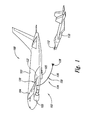
- FIG. 1 is a partially schematic, isometric illustration of a tanker aircraft having an aerial refueling device including a surge damping portion configured in accordance with several embodiments of the invention.
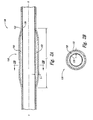
- Figure 2A is an enlarged, partially schematic side cross-sectional view of a portion of a hose assembly of the aerial refueling device and the surge damping portion shown in Figure 1.
- Figure 2B is a cross-sectional view of the hose assembly and the surge damping portion taken along line 2B-2B of Figure 2A.
- FIGS 3A-3C are enlarged, partially schematic side cross-sectional views of the surge damping portion illustrating stages of a method for damping or otherwise suppressing a surge load using the surge damping portion of Figures 1-2B.
- Figure 4 is an enlarged, partially schematic side cross-sectional view of a portion of a hose assembly and a surge damping portion configured in accordance with another embodiment of the invention.
- Figure 5 is an enlarged, partially schematic side cross-sectional view of a portion of a hose assembly and a surge damping portion configured in accordance with still another embodiment of the invention.
- Figure 6 is an enlarged, partially schematic side cross-sectional view of a portion of a hose assembly and a surge damping portion configured in accordance with yet another embodiment of the invention.
- the present disclosure describes systems and methods for reducing surge loads in hose assemblies, including surge loads in hose assemblies used in aircraft refueling systems. Certain specific details are set forth in the following description and in Figures 1-6 to provide a thorough understanding of various embodiments of the invention. Well-known structures, systems and methods often associated with such systems have not been shown or described in detail to avoid unnecessarily obscuring the description of the various embodiments of the invention. ln addition, those of ordinary skill in the relevant art will understand that additional embodiments of the invention may be practiced without several of the details described below.
- FIG 1 illustrates a system 100 that includes a tanker aircraft 102 positioned to couple with and refuel a receiver aircraft 110 using an aerial refueling device 120 configured in accordance with an embodiment of the invention.
- the tanker aircraft 102 has a fuselage 103, wings 104, and one or more engines 105 (two are shown in Figure 1 as being carried by the wings 104). In other embodiments, the aircraft 102 can have other configurations.
- the aerial refueling device 120 can include an on-board portion 122 (e.g., a hose reel activator and associated valving) and a deployable portion 124.
- the deployable portion 124 can include a flexible fuel line or hose 126 and a drogue 128.
- the position of the drogue 128 can be controlled to couple with a probe 112 of the receiver aircraft 110.
- the hose 126 can include one or more surge damping portions 150 (only one is shown in Figure 1) configured to damp or otherwise suppress surge loads traveling through the hose 126 from the drogue 128 toward the on-board portion 122 of the refueling device 120. Further details of the surge damping portion 150 and associated systems and methods for damping and/or suppressing surge loads are described below with reference to Figures 2A-6.
- FIG 2A is an enlarged, partially schematic side cross-sectional view of a portion of the hose 126 and the surge damping portion 150 shown in Figure 1.
- the hose 126 includes a fluid conduit having an inner portion or layer 130 surrounded by an outer portion or layer 132.
- the inner and outer layers 130 and 132 of the hose 126 extend along a longitudinal or flow axis F of the hose 126.
- the inner layer 130 of the hose 126 can be configured to carry fuel or other types of liquids.
- the inner layer 130 can include a soft rubber material that acts as a fluid seal.
- the inner layer 130 can also be configured to transmit surge loads into the surge damping portion 150.
- the outer layer 132 of the hose 126 is an outer body that can provide a protective shroud or layer around the inner layer 130 in case of a liquid and/or vapor leak in the inner layer 130. Accordingly, the outer layer 132 is generally isolated from fluid communication with the fuel or other liquid in the hose 126.
- the outer layer 132 can include a rubber material or other suitable material that meets the desired operational requirements for the hose 126 (e.g., flexibility, strength, rigidity, etc.)
- the inner layer 130 and/or the outer layer 132 of the hose 126 can be formed from other suitable materials or have other arrangements.
- FIG 2B is a cross-sectional view of the hose 126 and the surge damping portion 150 taken along line 2B-2B of Figure 2A.
- the surge damping portion 150 can include a compressible material 152 disposed annularly about the hose 126 such that the compressible material 152 is an integral part of the hose 126 between the inner layer 130 and the outer layer 132 of the hose 126.
- the compressible material 152 is positioned to absorb energy from a surge load traveling through the hose 126.
- the compressible material 152 can include solid rubber, foam rubber, silicone rubber, a foam material such as closed-cell foam or other suitable types of foam, or a variety of other suitable materials having the desired damping characteristics. Furthermore, in other embodiments described below with Figure 4 the compressible material can include a suitable gas.
- the compressible material 152 of the surge damping portion 150 can have a durometer value of approximately 10 to 90.
- the durometer value of the compressible material 152 can vary in accordance with the desired damping characteristics and/or operational requirements for the hose 126 and corresponding surge damping portion 150. Although compressible material 152 having a lower durometer value can improve the damping rate of the surge damping portion 150, the durometer value of the compressible material 152 should not be so low that the material overheats during operation. Furthermore, the durometer value of the compressible material 152 should be sufficient to provide the necessary stiffness to the hose 126 to meet the necessary operational requirements (e.g., flight loads during refueling operations). On the other hand, the durometer value should not be so high that the hose 126 and corresponding surge damping portion 150 are too stiff and/or do not have a desired damping functionality.
- the surge damping portion 150 has a length L (as shown in Figure 2A) along the hose 126 and a thickness T (shown in both Figures 2A and 2B) between the inner layer 130 and the outer layer 132 of the hose 126.
- the length L and thickness T of the surge damping portion 150 can be adjusted based on the desired damping characteristics for a particular application. In applications where large surge loads are expected, for example, the length L and/or thickness T can be increased to accommodate the larger loads. On the other hand, in applications where the surge loads are anticipated to be relatively small, the length L and/or thickness T of the surge damping portion 150 can be decreased.
- FIGs 3A-3C are enlarged, partially schematic side cross-sectional views of the surge damping portion 150 shown in Figures 1-2B illustrating stages of a method for damping or otherwise suppressing a surge load in accordance with an embodiment of the invention.
- Figure 3A illustrates a preliminary stage of the method in which a surge pulse or surge load 300 initially reaches the surge damping portion 150 of the hose 126.
- Surge pulses generated by fuel or other fluids passing through the hose 126, such as the surge pulse 300 in the illustrated embodiment generally include a radially expanding wave traveling along the hose from the drogue 128 ( Figure 1) toward the on-board portion of the refueling device 120 ( Figure 1).
- the surge pulse 300 is a wave traveling in a direction generally parallel to the flow axis F of the hose 126 (as shown by the arrows P).
- the inner layer 130 of the hose 126 includes a relatively soft rubber material configured to transmit the surge pulse 300 into the compressible material 152. Accordingly, when the surge pulse 300 reaches the surge damping portion 150 of the hose 126, the surge pulse 300 begins to expand into the compressible material 152 as shown in Figure 3A.
- the surge pulse 300 continues to travel in the direction P along the hose 126.
- the energy from the surge pulse 300 is transferred to the compressible material 152 as the surge pulse displaces portions of the compressible material.
- the energy from the surge pulse 300 is converted to heat and, accordingly, the surge pulse 300 itself begins to shrink or otherwise dissipate.
- the surge pulse 300 has passed through approximately half the length of the surge damping portion 150, and the surge pulse 300 is generally dissipated.
- the energy (i.e., heat, pressure, etc.) from the surge pulse 300 can be transferred to the compressible material 152, the hose 126, and/or the fluid (not shown) passing through the hose 126.
- the surge damping portion 150 is relatively light and inexpensive compared with conventional surge suppression systems that can include a series of pumps and tanks to charge the nitrogen-filled canisters, as described previously.
- An advantage of this feature is that the surge damping portions 150 can significantly decrease the operating weight of the aerial refueling device 120 ( Figure 1), which can increase efficiency and reduce the cost of operating the refueling system.
- Another advantage of this feature is that the complexity of the aerial refueling system is significantly reduced because the surge damping portion 150 does not require any additional tanks, pumps, or controllers for operation.
- the damping characteristics of the surge damping portion 150 are customizable based on anticipated loading conditions and/or operational conditions. For example, the length L and the thickness T of the compressible material 152 can be adjusted to accommodate a number of different loading conditions. The damping characteristics can be further adjusted by selecting a certain type of material having a desired durometer value for the compressible material 152.
- An advantage of these features is that a hose for an aerial refueling system (such as the aerial refueling device 120 of Figure 1) can be designed to satisfy a number of different operational conditions. Furthermore, additional hoses with different suppression characteristics can be designed for the system and can be quickly and easily exchanged with the existing hose to accommodate varying operational requirements.
- the surge damping portion of the hose 126 is positioned relatively close to the source of the surge loads (e.g., at or proximate to the drogue 128 ( Figure 1) at a distal end of the hose 126).
- An advantage of this feature is that it can be significantly more effective to dampen or otherwise suppress surge loads or surge pulses close to the source of the surge load when the surge load is at or near its peak because it is generally easier to transfer large amounts of energy from large surge loads as opposed to transferring energy from smaller surge loads.
- a large surge load will generally displace a larger volume of compressible material 152 and, accordingly, transfer more energy from the surge load to the compressible material 152.
- the surge damping portion 150 proximate to the distal end of the hose 126 is accordingly expected to significantly improve the ability of the system to dampen or otherwise suppress large surge loads as compared with conventional surge suppressors that are positioned within the aircraft a large distance away from the source of the surge loads.
- Figure 4 is an enlarged, partially schematic side cross-sectional view of a portion of a hose assembly 426 and a surge damping portion 450 configured in accordance with another embodiment of the invention.
- the hose assembly 426 and surge damping portion 450 can be used with the aerial refueling device 120 of Figure 1, or other suitable aerial refueling systems.
- the hose 426 illustrated in Figure 4 can be generally similar to the hose 126 described above with respect to Figures 2A and 2B.
- the hose 426 includes an inner layer or layer 430 surrounded by an outer layer or layer 432.
- the inner and outer layers 430 and 432 can be formed from materials generally similar to the inner and outer layers 130 and 132 of the hose 126 described above with respect to Figures 2A and 2B.
- the surge damping portion 450 can be positioned along a portion of the hose 426 to damp or otherwise suppress surge loads traveling along the hose 450.
- the surge damping portion 450 differs from the surge damping portion 150 described above with respect to Figures 2A-2B in that the surge damping portion 450 does not include a compressible material positioned between the inner and outer layers 430 and 432 of the hose 426.
- the surge damping portion 450 includes one or more bladders 452 (only one is shown in Figure 4) positioned between the inner and outer layers 430 and 432 of the hose 426.
- the bladder 452 is configured to be filled with a gas (e.g., air, nitrogen, or other suitable gases) using a gas supply 454 (shown schematically) operably coupled to the bladder 452.
- a gas e.g., air, nitrogen, or other suitable gases
- the bladder 452 can function in much the same way as the compressible material 152 of the surge damping portion 150 described above with respect to Figures 2A-3C.
- the bladder 452 can receive and dissipate surge loads in much the same way as the compressible material 152 described above.
- One particular aspect of this embodiment is that the pressure within the bladder 452 can be adjusted during operation to dynamically adjust the damping or suppressing characteristics of the surge damping portion 450 based on the anticipated surge loads and/or operational conditions. For example, in situations where the surge loads are anticipated to be relatively high, the pressure in the bladder 452 can be increased to withstand the large loads.
- hose 426 including the surge damping portion 450 can be used in a variety of operational situations, rather than requiring a user to change out the entire hose 426 or provide other types of additional surge suppression mechanisms to account for varying surge loads.
- a hose 526 in accordance with another embodiment of the invention includes an outer layer 532 and a surge damping portion 550 including compressible material 552 disposed annularly about the hose 526 and at least partially within the outer layer 532.
- the hose 526 may not include an inner layer if the compressible material 552 of the surge damping portion 550 includes a material suitable for contact with fuel or other types of liquids.
- a hose 626 in accordance with still another embodiment of the invention can include a surge damping portion 650 projecting inwardly from an outer layer 632 of the hose 626, rather than being in and/or between one or more layers of the hose 626.
- a surge damping portion 650 projecting inwardly from an outer layer 632 of the hose 626, rather than being in and/or between one or more layers of the hose 626.
Abstract
Description
- The present invention is directed generally toward reducing surge loads in hose assemblies, including reducing surge loads in hose assemblies used in systems for in-flight refueling of aircraft.
- In-flight refueling (or air-to-air refueling) is an important method for extending the range of aircraft traveling long distances over areas having no feasible landing or refueling points. Although in-flight refueling is a relatively common operation, especially for military aircraft, the aircraft to be refueled (e.g., the receiver aircraft) must be precisely positioned relative to the tanker aircraft in order to provide safe engagement while the fuel is dispensed to the receiver aircraft. The requirement for precise relative spatial positioning of the two rapidly moving aircraft makes in-flight refueling a challenging operation.
- There are currently two primary systems for in-flight refueling. One is a hose and drogue system, which includes a refueling hose having a drogue disposed at one end. The hose and drogue are trailed behind the tanker aircraft once the tanker aircraft is on station. The pilot of the receiver aircraft then flies the receiver aircraft to intercept and couple with the drogue for refueling. Another existing system is a boom refueling system. The boom refueling system typically includes a rigid boom extending from the tanker aircraft with a probe and nozzle at the distal end. The boom also includes airfoils controlled by a boom operator stationed on the refueling aircraft. The airfoils allow the boom operator to actively maneuver the boom with respect to the receiver aircraft, which flies in a fixed refueling position below and aft of the tanker aircraft.
- One challenge associated with in-flight refueling systems includes surge loads generated during the refueling process. For example, high surge pressures can be generated in the refueling hose by any sudden or rapid changes in the flow rate of fuel passing through the refueling hose (e.g., starting or stopping the fuel flow, increasing or decreasing the fuel flow, etc.) The sudden changes in flow rate can in turn cause surge loads or surge pulses in the system, which can travel up the refueling hose and back into the tanker aircraft fuel system. In some instances, the surge loads can damage the various components of the fuel system (e.g., pumps, tanks, plumbing, etc.) and/or other aircraft systems or components. One approach for damping or otherwise suppressing such surge loads is to use surge suppressors positioned within the aircraft at various locations along the fuel system to intercept the surge loads. Conventional surge suppressors can include, for example, one or more canisters having bladders or other types of suppression areas positioned to absorb at least a portion of the surge loads before the loads can potentially damage the various systems of the aircraft.
- One drawback with conventional surge suppressors, however, is that they are typically not designed for the large surge loads generated during in-flight refueling operations. Most surge suppressors are only configured to handle the relatively small surge loads generated during ground refueling operations, rather than the large surge loads that can be generated during in-flight refueling operations. Another drawback with conventional surge suppressors is that the bladders need to be filled or "charged" with nitrogen or another suitable gas both before and during use. The charging process can be time-consuming and inefficient, and can create a requirement for additional hardware on the aircraft (e.g., pumps, tanks, plumbing, etc.) Still another drawback with conventional surge suppressors is that the performance of the suppressors can change significantly based on the operating conditions of the aircraft. For example, the gas in the bladder can be affected by changes in temperature and/or pressure as the aircraft is in flight. Such changes can negatively affect the performance of the surge suppressor, particularly during in-flight refueling operations when the generated surge loads can be relatively large. Accordingly, there is a need to improve the systems and methods for suppressing or otherwise reducing surge loads in hose assemblies.
- The following summary is provided for the benefit of the reader only, and does not limit the invention. Aspects of the invention are directed generally to aerial refueling systems. An airborne refueling system in accordance with one aspect of the invention includes a fuel delivery device having a flexible fuel line configured to be deployed overboard an aircraft during aerial refueling and a drogue coupled to the fuel line. The system can further include a surge damping portion positioned along the fuel line away from the aircraft to suppress surge loads traveling along the fuel line.
- In several embodiments, the surge damping portion can include a compressible material disposed annularly about at least a portion of the fuel line. The compressible material can include, for example, solid rubber, foam rubber, silicone rubber, a foam material such as closed-cell foam or other suitable types of foam, or other suitable materials having a desired damping characteristic. In other embodiments, the surge damping portion and corresponding compressible material can include a bladder disposed annularly about at least a portion of the fuel line at least partially filled with a gas (e.g., air or another suitable gas). In still further embodiments, the system can include a plurality of surge damping portions positioned along the fuel line away from the aircraft.
- A system for reducing surge loads in hose assemblies in accordance with another aspect of the invention can include a hose having a first segment and a second segment. The hose can include any type of flexible fluid conduit configured to carry a fluid. The system can further include a surge damping portion positioned annularly about at least a portion of the second segment of the hose. The surge damping portion is positioned to dampen radially expanding surge loads traveling along a longitudinal axis of the hose. In several embodiments, the surge damping portion can include a compressible material disposed annularly about at least a portion of the second segment of the hose.
- A method for refueling an aircraft in accordance with another aspect of the invention can include aerially deploying from a tanker aircraft a portion of a refueling system that includes a flexible fuel line and a drogue. The method can further include suppressing surge loads traveling along the fuel line using a surge damping portion positioned along at least a portion of the fuel line away from the tanker aircraft. In several embodiments, for example, suppressing surge loads traveling along the fuel line includes transferring energy from radially expanding surge loads into a compressible material disposed annularly about at least a portion of the fuel line.
- Figure 1 is a partially schematic, isometric illustration of a tanker aircraft having an aerial refueling device including a surge damping portion configured in accordance with several embodiments of the invention.
- Figure 2A is an enlarged, partially schematic side cross-sectional view of a portion of a hose assembly of the aerial refueling device and the surge damping portion shown in Figure 1.
- Figure 2B is a cross-sectional view of the hose assembly and the surge damping portion taken along
line 2B-2B of Figure 2A. - Figures 3A-3C are enlarged, partially schematic side cross-sectional views of the surge damping portion illustrating stages of a method for damping or otherwise suppressing a surge load using the surge damping portion of Figures 1-2B.
- Figure 4 is an enlarged, partially schematic side cross-sectional view of a portion of a hose assembly and a surge damping portion configured in accordance with another embodiment of the invention.
- Figure 5 is an enlarged, partially schematic side cross-sectional view of a portion of a hose assembly and a surge damping portion configured in accordance with still another embodiment of the invention.
- Figure 6 is an enlarged, partially schematic side cross-sectional view of a portion of a hose assembly and a surge damping portion configured in accordance with yet another embodiment of the invention.
- The present disclosure describes systems and methods for reducing surge loads in hose assemblies, including surge loads in hose assemblies used in aircraft refueling systems. Certain specific details are set forth in the following description and in Figures 1-6 to provide a thorough understanding of various embodiments of the invention. Well-known structures, systems and methods often associated with such systems have not been shown or described in detail to avoid unnecessarily obscuring the description of the various embodiments of the invention. ln addition, those of ordinary skill in the relevant art will understand that additional embodiments of the invention may be practiced without several of the details described below.
- Figure 1 illustrates a
system 100 that includes atanker aircraft 102 positioned to couple with and refuel areceiver aircraft 110 using anaerial refueling device 120 configured in accordance with an embodiment of the invention. Thetanker aircraft 102 has afuselage 103,wings 104, and one or more engines 105 (two are shown in Figure 1 as being carried by the wings 104). In other embodiments, theaircraft 102 can have other configurations. ln a particular aspect of the embodiment shown in Figure 1, theaerial refueling device 120 can include an on-board portion 122 (e.g., a hose reel activator and associated valving) and adeployable portion 124. Thedeployable portion 124 can include a flexible fuel line orhose 126 and adrogue 128. The position of thedrogue 128 can be controlled to couple with aprobe 112 of thereceiver aircraft 110. Thehose 126 can include one or more surge damping portions 150 (only one is shown in Figure 1) configured to damp or otherwise suppress surge loads traveling through thehose 126 from thedrogue 128 toward the on-board portion 122 of therefueling device 120. Further details of thesurge damping portion 150 and associated systems and methods for damping and/or suppressing surge loads are described below with reference to Figures 2A-6. - Figure 2A is an enlarged, partially schematic side cross-sectional view of a portion of the
hose 126 and thesurge damping portion 150 shown in Figure 1. Thehose 126 includes a fluid conduit having an inner portion orlayer 130 surrounded by an outer portion orlayer 132. The inner andouter layers hose 126 extend along a longitudinal or flow axis F of thehose 126. Theinner layer 130 of thehose 126 can be configured to carry fuel or other types of liquids. In several embodiments, for example, theinner layer 130 can include a soft rubber material that acts as a fluid seal. As described in greater detail below, theinner layer 130 can also be configured to transmit surge loads into thesurge damping portion 150. - The
outer layer 132 of thehose 126 is an outer body that can provide a protective shroud or layer around theinner layer 130 in case of a liquid and/or vapor leak in theinner layer 130. Accordingly, theouter layer 132 is generally isolated from fluid communication with the fuel or other liquid in thehose 126. Theouter layer 132 can include a rubber material or other suitable material that meets the desired operational requirements for the hose 126 (e.g., flexibility, strength, rigidity, etc.) In other embodiments, theinner layer 130 and/or theouter layer 132 of thehose 126 can be formed from other suitable materials or have other arrangements. - Figure 2B is a cross-sectional view of the
hose 126 and thesurge damping portion 150 taken alongline 2B-2B of Figure 2A. Referring to Figures 2A and 2B together, thesurge damping portion 150 can include acompressible material 152 disposed annularly about thehose 126 such that thecompressible material 152 is an integral part of thehose 126 between theinner layer 130 and theouter layer 132 of thehose 126. As described in greater detail below with respect to Figures 3A-3C, thecompressible material 152 is positioned to absorb energy from a surge load traveling through thehose 126. Thecompressible material 152 can include solid rubber, foam rubber, silicone rubber, a foam material such as closed-cell foam or other suitable types of foam, or a variety of other suitable materials having the desired damping characteristics. Furthermore, in other embodiments described below with Figure 4 the compressible material can include a suitable gas. - The
compressible material 152 of thesurge damping portion 150 can have a durometer value of approximately 10 to 90. The durometer value of thecompressible material 152 can vary in accordance with the desired damping characteristics and/or operational requirements for thehose 126 and correspondingsurge damping portion 150. Althoughcompressible material 152 having a lower durometer value can improve the damping rate of thesurge damping portion 150, the durometer value of thecompressible material 152 should not be so low that the material overheats during operation. Furthermore, the durometer value of thecompressible material 152 should be sufficient to provide the necessary stiffness to thehose 126 to meet the necessary operational requirements (e.g., flight loads during refueling operations). On the other hand, the durometer value should not be so high that thehose 126 and correspondingsurge damping portion 150 are too stiff and/or do not have a desired damping functionality. - In the illustrated embodiment, the
surge damping portion 150 has a length L (as shown in Figure 2A) along thehose 126 and a thickness T (shown in both Figures 2A and 2B) between theinner layer 130 and theouter layer 132 of thehose 126. The length L and thickness T of thesurge damping portion 150 can be adjusted based on the desired damping characteristics for a particular application. In applications where large surge loads are expected, for example, the length L and/or thickness T can be increased to accommodate the larger loads. On the other hand, in applications where the surge loads are anticipated to be relatively small, the length L and/or thickness T of thesurge damping portion 150 can be decreased. - Figures 3A-3C are enlarged, partially schematic side cross-sectional views of the
surge damping portion 150 shown in Figures 1-2B illustrating stages of a method for damping or otherwise suppressing a surge load in accordance with an embodiment of the invention. Figure 3A, for example, illustrates a preliminary stage of the method in which a surge pulse orsurge load 300 initially reaches thesurge damping portion 150 of thehose 126. Surge pulses generated by fuel or other fluids passing through thehose 126, such as thesurge pulse 300 in the illustrated embodiment, generally include a radially expanding wave traveling along the hose from the drogue 128 (Figure 1) toward the on-board portion of the refueling device 120 (Figure 1). In the illustrated embodiment, for example, thesurge pulse 300 is a wave traveling in a direction generally parallel to the flow axis F of the hose 126 (as shown by the arrows P). ln one particular aspect of this embodiment, theinner layer 130 of thehose 126 includes a relatively soft rubber material configured to transmit thesurge pulse 300 into thecompressible material 152. Accordingly, when thesurge pulse 300 reaches thesurge damping portion 150 of thehose 126, thesurge pulse 300 begins to expand into thecompressible material 152 as shown in Figure 3A. - Referring next to Figure 3B, the
surge pulse 300 continues to travel in the direction P along thehose 126. As thesurge pulse 300 passes through thecompressible material 152 of thesurge damping portion 150, however, the energy from thesurge pulse 300 is transferred to thecompressible material 152 as the surge pulse displaces portions of the compressible material. In this way, the energy from thesurge pulse 300 is converted to heat and, accordingly, thesurge pulse 300 itself begins to shrink or otherwise dissipate. Referring to Figure 3C, for example, thesurge pulse 300 has passed through approximately half the length of thesurge damping portion 150, and thesurge pulse 300 is generally dissipated. As discussed previously, the energy (i.e., heat, pressure, etc.) from thesurge pulse 300 can be transferred to thecompressible material 152, thehose 126, and/or the fluid (not shown) passing through thehose 126. - One feature of at least some of the embodiments of the
surge damping portion 150 described above is that thesurge damping portion 150 is relatively light and inexpensive compared with conventional surge suppression systems that can include a series of pumps and tanks to charge the nitrogen-filled canisters, as described previously. An advantage of this feature is that thesurge damping portions 150 can significantly decrease the operating weight of the aerial refueling device 120 (Figure 1), which can increase efficiency and reduce the cost of operating the refueling system. Another advantage of this feature is that the complexity of the aerial refueling system is significantly reduced because thesurge damping portion 150 does not require any additional tanks, pumps, or controllers for operation. - Another feature of at least some of the embodiments of the
surge damping portion 150 described above is that the damping characteristics of thesurge damping portion 150 are customizable based on anticipated loading conditions and/or operational conditions. For example, the length L and the thickness T of thecompressible material 152 can be adjusted to accommodate a number of different loading conditions. The damping characteristics can be further adjusted by selecting a certain type of material having a desired durometer value for thecompressible material 152. An advantage of these features is that a hose for an aerial refueling system (such as theaerial refueling device 120 of Figure 1) can be designed to satisfy a number of different operational conditions. Furthermore, additional hoses with different suppression characteristics can be designed for the system and can be quickly and easily exchanged with the existing hose to accommodate varying operational requirements. - Still another feature of at least some of the embodiments of the
surge damping portion 150 described above is that the surge damping portion of thehose 126 is positioned relatively close to the source of the surge loads (e.g., at or proximate to the drogue 128 (Figure 1) at a distal end of the hose 126). An advantage of this feature is that it can be significantly more effective to dampen or otherwise suppress surge loads or surge pulses close to the source of the surge load when the surge load is at or near its peak because it is generally easier to transfer large amounts of energy from large surge loads as opposed to transferring energy from smaller surge loads. For example, a large surge load will generally displace a larger volume ofcompressible material 152 and, accordingly, transfer more energy from the surge load to thecompressible material 152. Thesurge damping portion 150 proximate to the distal end of thehose 126 is accordingly expected to significantly improve the ability of the system to dampen or otherwise suppress large surge loads as compared with conventional surge suppressors that are positioned within the aircraft a large distance away from the source of the surge loads. - Figure 4 is an enlarged, partially schematic side cross-sectional view of a portion of a
hose assembly 426 and asurge damping portion 450 configured in accordance with another embodiment of the invention. Thehose assembly 426 and surge dampingportion 450 can be used with theaerial refueling device 120 of Figure 1, or other suitable aerial refueling systems. Thehose 426 illustrated in Figure 4 can be generally similar to thehose 126 described above with respect to Figures 2A and 2B. For example, thehose 426 includes an inner layer orlayer 430 surrounded by an outer layer orlayer 432. The inner andouter layers outer layers hose 126 described above with respect to Figures 2A and 2B. - The
surge damping portion 450 can be positioned along a portion of thehose 426 to damp or otherwise suppress surge loads traveling along thehose 450. Thesurge damping portion 450 differs from thesurge damping portion 150 described above with respect to Figures 2A-2B in that thesurge damping portion 450 does not include a compressible material positioned between the inner andouter layers hose 426. Instead, thesurge damping portion 450 includes one or more bladders 452 (only one is shown in Figure 4) positioned between the inner andouter layers hose 426. Thebladder 452 is configured to be filled with a gas (e.g., air, nitrogen, or other suitable gases) using a gas supply 454 (shown schematically) operably coupled to thebladder 452. - The
bladder 452 can function in much the same way as thecompressible material 152 of thesurge damping portion 150 described above with respect to Figures 2A-3C. For example, thebladder 452 can receive and dissipate surge loads in much the same way as thecompressible material 152 described above. One particular aspect of this embodiment, however, is that the pressure within thebladder 452 can be adjusted during operation to dynamically adjust the damping or suppressing characteristics of thesurge damping portion 450 based on the anticipated surge loads and/or operational conditions. For example, in situations where the surge loads are anticipated to be relatively high, the pressure in thebladder 452 can be increased to withstand the large loads. In other operational situations (either during the same refueling operation or during another refueling operation) when the surge loads are anticipated to be smaller, the pressure in thebladder 452 can be decreased. An advantage of this feature is that thehose 426 including thesurge damping portion 450 can be used in a variety of operational situations, rather than requiring a user to change out theentire hose 426 or provide other types of additional surge suppression mechanisms to account for varying surge loads.
[c1] From the foregoing, it will be appreciated that specific embodiments of the invention have been described herein for purposes of illustration, but that various modifications may be made without deviating from the invention. For example, a hose assembly can include any number of surge suppression portions along the hose to reduce surge loads in the hose. Furthermore, in several embodiments the hose assembly and/or surge suppression portions may have other configurations. Referring to Figure 5, for example, ahose 526 in accordance with another embodiment of the invention includes anouter layer 532 and asurge damping portion 550 includingcompressible material 552 disposed annularly about thehose 526 and at least partially within theouter layer 532. In one particular aspect of this embodiment, thehose 526 may not include an inner layer if thecompressible material 552 of thesurge damping portion 550 includes a material suitable for contact with fuel or other types of liquids. Referring to Figure 6, ahose 626 in accordance with still another embodiment of the invention can include asurge damping portion 650 projecting inwardly from anouter layer 632 of thehose 626, rather than being in and/or between one or more layers of thehose 626. Aspects of the invention described in the context of particular embodiments may be combined or eliminated in other embodiments. For example, the surge damping features and methods described in the context of specific aircraft refueling systems can be implemented in a number of other aircraft or non-aircraft systems that include hose assemblies or fluid conduits where surge loads are an issue (e.g., petroleum industry applications, automotive applications, industrial or residential plumbing systems, etc.). Certain aspects of the invention are accordingly not limited to aircraft refueling systems. Further, while advantages associated with certain embodiments of the invention have been described in the context of those embodiments, other embodiments may also exhibit such advantages, and not all embodiments need necessarily exhibit such advantages to fall within the scope of the invention. Accordingly, the invention is not limited except as by the appended claims.
Claims (22)
- An aerial refueling system, comprising:a fuel delivery device that includes:a flexible fuel line configured to be deployed overboard an aircraft during aerial refueling;a drogue coupled to the fuel line; anda surge damping portion positioned along the fuel line away from the aircraft to suppress surge loads traveling along the fuel line.
- The system of claim 1 wherein the surge damping portion includes a compressible material disposed annularly about at least a portion of the fuel line.
- The system of claim 2 wherein:the fuel line includes (a) an inner layer positioned to transmit the surge loads into the surge damping portion, and (b) an outer layer disposed annularly about at least a portion of the inner layer and the surge damping portion; andthe compressible material includes one or more bladders between the inner layer and the outer layer and positioned to be at least partially filled with a gas.
- The system of claim 3 wherein the one or more bladders between the inner layer and outer layer are positioned to be at least partially filled with air.
- The system of any of claims 1-4 wherein the fuel delivery device includes a plurality of surge damping portions along the fuel line away from the aircraft.
- The system of any of claims 1-5, further comprising the aircraft, wherein the aircraft includes a tanker aircraft, and wherein the fuel delivery device is carried by the tanker aircraft.
- The system of any of claims 1-6 wherein the fuel line includes:a first portion configured to remain aboard the aircraft; anda second portion configured to be deployed overboard the aircraft, and wherein the surge damping portion is in the second portion of the fuel line.
- The system of any of claims 1-7 further comprising the aircraft, wherein the aircraft includes a tanker aircraft, and wherein:the fuel delivery device is carried by the tanker aircraft and includes a deployable portion configured to be deployed overboard the tanker aircraft during aerial refueling, the deployable portion including:at least a portion of the fuel line, the fuel line including (a) an inner layer positioned to transmit the surge loads into the surge damping portion, and (b) an outer layer disposed annularly about at least a portion of the inner layer and the surge damping portion;the drogue; andthe surge damping portion positioned along the fuel line, the surge damping portion including a compressible material disposed annularly about at least a portion of the fuel line between the inner layer of the fuel line and the outer layer of the fuel line to dampen radially expanding surge loads traveling along a flow axis of the fuel line.
- A system for reducing surge loads in hose assemblies, the system comprising:a hose configured to carry a fluid, the hose including a first segment and a second segment; anda surge damping portion positioned annularly about at least a portion of the second segment of the hose, the surge damping portion being positioned to dampen radially expanding surge loads traveling along a longitudinal axis of the hose.
- The system of claim 9 wherein the surge damping portion is integral with the second segment of the hose.
- The system of claim 9 or 10 wherein the surge damping portion includes a compressible material disposed annularly about at least a portion of the second segment of the hose.
- The system of any of claims 1-11 wherein the hose or fuel line includes:an inner layer positioned to transmit the surge loads into the compressible material; andan outer layer disposed annularly about at least a portion of the inner layer and the compressible material.
- The system of any of claims 3-12 wherein the compressible material includes at least one of a solid rubber, foam rubber, silicone rubber, closed-cell foam, and a foam material.
- The system of any of claims 3-13 wherein the compressible material has a durometer value of 10 to 90.
- The system of any of claims 1-14 wherein:the hose includes (a) an inner layer positioned to transmit the surge loads into the compressible material, and (b) an outer layer disposed annularly about at least a portion of the inner layer and the compressible material; andthe compressible material includes one or more bladders between the inner layer and the outer layer and positioned to be at least partially filled with a gas.
- The system of any of claims 1-15 wherein the hose includes a plurality of surge damping portions along the second segment of the hose.
- A method for refueling an aircraft, comprising:aerially deploying from a tanker aircraft a portion of a refueling system that includes a flexible fuel line and a drogue; andsuppressing surge loads traveling along the fuel line using a surge damping portion positioned along at least a portion of the fuel line away from the tanker aircraft.
- The method of claim 17 wherein suppressing surge loads traveling along the fuel line using a surge damping portion includes transferring energy from radially expanding surge loads into a compressible material disposed radially about at least a portion of the fuel line.
- The method of claim 18 wherein transferring energy from radially expanding surge loads into a compressible material includes transferring energy from the surge loads into a compressible material including at least one of a solid rubber, foam rubber, silicone rubber, closed-cell foam, and a foam material.
- The method of claim 18 or 19 wherein transferring energy from radially expanding surge loads into a compressible material includes transferring energy from the surge loads into a compressible material including a bladder at least partially filled with a gas.
- The method of claim 20, further comprising controlling the rate at which energy from the surge loads is transferred into the bladder by adjustably controlling the gas pressure in the bladder.
- The method of any of claims 17-21 wherein suppressing surge loads traveling along the fuel line using a surge damping portion includes suppressing surge loads using a plurality of surge damping portions positioned along the fuel line away from the aircraft.
Applications Claiming Priority (1)
| Application Number | Priority Date | Filing Date | Title |
|---|---|---|---|
| US11/258,819 US20070102583A1 (en) | 2005-10-26 | 2005-10-26 | Systems and methods for reducing surge loads in hose assemblies, including aircraft refueling hose assemblies |
Publications (3)
| Publication Number | Publication Date |
|---|---|
| EP1780123A2 true EP1780123A2 (en) | 2007-05-02 |
| EP1780123A3 EP1780123A3 (en) | 2007-12-05 |
| EP1780123B1 EP1780123B1 (en) | 2011-08-24 |
Family
ID=37591871
Family Applications (1)
| Application Number | Title | Priority Date | Filing Date |
|---|---|---|---|
| EP06076917A Active EP1780123B1 (en) | 2005-10-26 | 2006-10-23 | Systems and methods for reducing surge loads in hose assemblies, including aircraft refueling hose assemblies |
Country Status (4)
| Country | Link |
|---|---|
| US (1) | US20070102583A1 (en) |
| EP (1) | EP1780123B1 (en) |
| AT (1) | ATE521536T1 (en) |
| ES (1) | ES2370332T3 (en) |
Cited By (1)
| Publication number | Priority date | Publication date | Assignee | Title |
|---|---|---|---|---|
| WO2014199132A1 (en) * | 2013-06-12 | 2014-12-18 | Airbus Operations Limited | Aircraft fuel vent pipe |
Families Citing this family (13)
| Publication number | Priority date | Publication date | Assignee | Title |
|---|---|---|---|---|
| US7293741B2 (en) * | 2005-06-09 | 2007-11-13 | The Boeing Company | System and methods for distributing loads from fluid conduits, including aircraft fuel conduits |
| US7581700B2 (en) * | 2005-06-09 | 2009-09-01 | The Boeing Company | Adjustable fittings for attaching support members to fluid conduits, including aircraft fuel conduits, and associated systems and methods |
| US7533850B2 (en) | 2005-06-09 | 2009-05-19 | The Boeing Company | Fittings with redundant seals for aircraft fuel lines, fuel tanks, and other systems |
| US20090091126A1 (en) * | 2007-10-04 | 2009-04-09 | Carns James A | Shrouded coupling assemblies for conduits |
| US9360144B2 (en) * | 2007-10-22 | 2016-06-07 | The Boeing Company | Conduit with joint covered by a boot |
| US7942452B2 (en) * | 2007-11-20 | 2011-05-17 | The Boeing Company | Flange fitting with leak sensor port |
| JP5191292B2 (en) * | 2008-07-08 | 2013-05-08 | オリンパス株式会社 | Incubator |
| US8232706B2 (en) | 2009-01-09 | 2012-07-31 | The Boeing Company | Autonomous power generation unit for auxiliary system on an airborne platform |
| US8220746B1 (en) * | 2009-05-29 | 2012-07-17 | The Boeing Company | Broad speed range inflatable drogue canopy |
| US8398028B1 (en) * | 2010-11-16 | 2013-03-19 | The Boeing Company | Drogue with power generator |
| AU2017219127B2 (en) * | 2016-04-18 | 2019-03-14 | Guangzhou Xaircraft Technology Co., Ltd. | Liquid volume transfer system, liquid infusion device, unmanned aerial vehicle and liquid container |
| EP3584167B1 (en) * | 2018-06-19 | 2022-04-06 | Airbus Defence and Space, S.A.U. | Air to air refuelling hose and method for detecting damages in air to air refuelling hose |
| GB2569690B (en) * | 2018-10-26 | 2020-01-01 | pitman James | Fuel hose assembly for in-flight fuelling of aircraft |
Family Cites Families (101)
| Publication number | Priority date | Publication date | Assignee | Title |
|---|---|---|---|---|
| US724675A (en) * | 1902-08-29 | 1903-04-07 | William M Ferry | Fluid-conducting pipe. |
| US2091916A (en) * | 1936-04-27 | 1937-08-31 | Hughes Tool Co | Pipe clamp |
| US2213680A (en) * | 1939-12-08 | 1940-09-03 | Share Barnett | Valve for well point systems |
| US2414509A (en) * | 1944-06-02 | 1947-01-21 | Lockheed Aircraft Corp | Bulkhead mounting for conduits |
| US2475635A (en) * | 1945-01-08 | 1949-07-12 | Elmer C Parsons | Multiple conduit |
| US2552991A (en) * | 1948-04-16 | 1951-05-15 | South Hosuton Machine Company | Valve assembly |
| US2712831A (en) * | 1948-11-27 | 1955-07-12 | Grover A Day | Shock pressure absorber and pulsation dampers |
| US2953332A (en) * | 1950-03-31 | 1960-09-20 | Flight Refueling Ltd | Apparatus for towing and refuelling aircraft in flight |
| US2670913A (en) * | 1950-04-24 | 1954-03-02 | Boeing Co | Aircraft boom control and balancing mechanism |
| US2668066A (en) * | 1951-02-10 | 1954-02-02 | Berkeley Pump Company | Coupling means for tubular casing |
| US2852216A (en) * | 1954-09-16 | 1958-09-16 | Melville F Peters | Refueling conduit |
| US2879017A (en) * | 1955-01-25 | 1959-03-24 | Flight Refueling Inc | Apparatus for interconnecting aircraft in flight |
| US2954190A (en) * | 1955-03-07 | 1960-09-27 | Parker Hannifin Corp | Hose reel and control mechanism therefor |
| US2875787A (en) * | 1956-03-27 | 1959-03-03 | Westinghouse Air Brake Co | Pulsation dampener device |
| US2919937A (en) * | 1956-07-30 | 1960-01-05 | Federal Mogul Bower Bearings | Pipe coupling having inflated sealing means |
| US3091419A (en) * | 1957-01-14 | 1963-05-28 | Schulz Tool & Mfg Co | Aircraft in-flight refueling system |
| US2973171A (en) * | 1957-01-15 | 1961-02-28 | Flight Refueling Inc | In-flight connection for aircraft |
| US2946543A (en) * | 1957-01-25 | 1960-07-26 | Textron Inc | Aerodynamic drag device |
| US2941761A (en) * | 1957-08-22 | 1960-06-21 | Textron Inc | Guidance system for aerial refueling |
| US3061246A (en) * | 1957-12-23 | 1962-10-30 | Vitro Corp Of America | Flying pipe refueling system |
| US3206232A (en) * | 1958-11-12 | 1965-09-14 | Boeing Co | Tube fitting |
| US2967684A (en) * | 1958-12-31 | 1961-01-10 | Robert S Knecht | Combination inflight refueling and dumping for helicopters |
| US3103234A (en) * | 1961-02-08 | 1963-09-10 | Beloit Iron Works | Fluid flow surge dampening system |
| US3108769A (en) * | 1961-09-18 | 1963-10-29 | Schulz Tool & Mfg Co | Ring wing drogue |
| US3181899A (en) * | 1964-01-27 | 1965-05-04 | Corning Glass Works | Assembly for connecting pipe to an apertured tank |
| US3665967A (en) * | 1970-01-16 | 1972-05-30 | Western Co Of North America | Supercharge hose |
| FR2082386A5 (en) * | 1970-03-12 | 1971-12-10 | Inst Francais Du Petrole | |
| US3747873A (en) * | 1971-11-19 | 1973-07-24 | Susquehanna Corp | Tow cable assembly |
| US3836117A (en) * | 1973-03-20 | 1974-09-17 | M Panicali | Valve cap |
| US4044834A (en) * | 1975-04-09 | 1977-08-30 | Perkins Lee E | Apparatus and method for controlling the flow of fluids from a well bore |
| DE2544001A1 (en) * | 1975-10-02 | 1977-04-07 | Schneider Co Optische Werke | PRESSURE VALVE |
| US4088154A (en) * | 1976-06-07 | 1978-05-09 | Mobil Oil Corporation | Automatically controlled desurging system |
| US4095761A (en) * | 1976-09-29 | 1978-06-20 | The Boeing Company | Aerial refueling spoiler |
| US4072283A (en) * | 1976-12-17 | 1978-02-07 | The Boeing Company | Aerial refueling boom articulation |
| US4149739A (en) * | 1977-03-18 | 1979-04-17 | Summa Corporation | Dual passage pipe for cycling water to an undersea mineral aggregate gathering apparatus |
| US4150803A (en) * | 1977-10-05 | 1979-04-24 | Fernandez Carlos P | Two axes controller |
| US4477040A (en) * | 1978-10-19 | 1984-10-16 | Grumman Aerospace Corporation | Aircraft wind energy device |
| US4586683A (en) * | 1979-03-12 | 1986-05-06 | Mcdonnell Douglas Corporation | Rolling aerial refueling boom |
| US4340079A (en) * | 1980-02-15 | 1982-07-20 | Grove Valve And Regulator Company | Energy dissipating pipeline surge relief system |
| US4327784A (en) * | 1980-06-09 | 1982-05-04 | Rockwell International Corporation | Apparatus for refueling an aircraft from a ship at sea |
| US4408943A (en) * | 1981-02-27 | 1983-10-11 | Fmc Corporation | Ship-to-ship fluid transfer system |
| US4438793A (en) * | 1981-05-04 | 1984-03-27 | International Telephone & Telegraph Corp. | Aerial refueling boom nozzle |
| DE3126041C2 (en) * | 1981-07-02 | 1985-11-28 | Danfoss A/S, Nordborg | Hydraulic control device with an adjustable throttle |
| US4437487A (en) * | 1981-08-31 | 1984-03-20 | Lockheed Corporation | Lightning protected check-type drain valve |
| US4534384A (en) * | 1982-12-15 | 1985-08-13 | Flight Refueling, Inc. | Reel system for axially extending hose |
| CH669856A5 (en) * | 1984-01-04 | 1989-04-14 | Lonza Ag | |
| US4540144A (en) * | 1984-01-05 | 1985-09-10 | United Technologies Corporation | Telescoping fuel probe |
| US4612089A (en) * | 1984-03-16 | 1986-09-16 | Devron Engineering Ltd. | Surge suppression device |
| US4654612A (en) * | 1984-12-18 | 1987-03-31 | Andrew Corporation | Spring hanger system for UHF circular waveguide having glide ring and clamping ring connected by constant force springs |
| USH297H (en) * | 1985-08-12 | 1987-07-07 | The United States Of America As Represented By The Secretary Of The Air Force | Robotic refueling system for tactical and strategic aircraft |
| US4717099A (en) * | 1986-05-15 | 1988-01-05 | Hubbard George R | Fire sprinkler alignment bracket |
| US4796838A (en) * | 1988-01-14 | 1989-01-10 | The United States Of America As Represented By The Secretary Of The Air Force | Hose reel monitor for inflight refueling system |
| US5141178A (en) * | 1988-02-19 | 1992-08-25 | Whittaker Controls, Inc. | Aerial refueling system |
| US4929000A (en) * | 1988-12-02 | 1990-05-29 | American Metal Products Company | Multiple walled chimney |
| GB2228771A (en) * | 1989-01-27 | 1990-09-05 | Smr Technologies Inc | Refuelling surge boot |
| US5131438A (en) * | 1990-08-20 | 1992-07-21 | E-Systems, Inc. | Method and apparatus for unmanned aircraft in flight refueling |
| US5449203A (en) * | 1991-04-04 | 1995-09-12 | Sharp; Bruce R. | Fittings for connection to double wall pipeline systems |
| US5326052A (en) * | 1991-10-02 | 1994-07-05 | Enig Associates, Inc. | Controllable hose-and-drogue in-flight refueling system |
| US5427333A (en) * | 1992-10-21 | 1995-06-27 | West Coast Netting, Inc. | Variable speed drogue |
| US5255877A (en) * | 1992-10-21 | 1993-10-26 | West Coast Netting, Inc. | Variable speed drogue |
| US5530650A (en) * | 1992-10-28 | 1996-06-25 | Mcdonnell Douglas Corp. | Computer imaging system and method for remote in-flight aircraft refueling |
| FR2705082B1 (en) * | 1993-05-12 | 1995-08-04 | Aerospatiale | In-flight refueling system. |
| US5393015A (en) * | 1993-06-01 | 1995-02-28 | Piasecki Aircraft Corporation | Rotary wing aircraft in-flight refueling device |
| US5449204A (en) * | 1993-10-22 | 1995-09-12 | Greene; Karen C. | Double containment fitting |
| US5539624A (en) * | 1995-01-17 | 1996-07-23 | Durodyne, Inc. | Illuminated hose |
| US5785276A (en) * | 1995-12-22 | 1998-07-28 | The Boeing Company | Actuated roll axis aerial refueling boom |
| US5810292A (en) * | 1996-07-24 | 1998-09-22 | Sargent Fletcher, Inc. | Aerial refueling system with telescoping refueling probe |
| US6408429B1 (en) * | 1997-01-17 | 2002-06-18 | Cognex Corporation | Machine vision system for identifying and assessing features of an article |
| US6119981A (en) * | 1997-03-04 | 2000-09-19 | Flight Refuelling Limited | Drogue assembly for in-flight refuelling |
| US5904729A (en) * | 1997-03-04 | 1999-05-18 | The Boeing Company | Automated director light system for aerial refueling operations |
| DE29710006U1 (en) * | 1997-06-09 | 1998-11-05 | Buerkert Werke Gmbh & Co | Miniaturized valve device |
| JP3492499B2 (en) * | 1997-08-05 | 2004-02-03 | シャープ株式会社 | Image forming device |
| US5906336A (en) * | 1997-11-14 | 1999-05-25 | Eckstein; Donald | Method and apparatus for temporarily interconnecting an unmanned aerial vehicle |
| NL1007899C2 (en) * | 1997-12-24 | 1999-06-25 | Dhv Water Bv | Coupling element for membrane elements. |
| US5921294A (en) * | 1998-03-04 | 1999-07-13 | The United States Of America As Represented By The Secretary Of The Navy | Air refueling drogue |
| IT244388Y1 (en) * | 1998-11-23 | 2002-03-11 | Nupi S P A | FITTINGS FOR DOUBLE WALL PIPES |
| US6454212B1 (en) * | 2000-08-22 | 2002-09-24 | Asher Bartov | Aerial refueling hose reel drive controlled by a variable displacement hydraulic motor and method for controlling aerial refueling hose reel |
| US6866228B2 (en) * | 2000-07-21 | 2005-03-15 | Asher Bartov | Aerial refueling hose reel drive controlled by a variable displacement hydraulic motor and method for controlling aerial refueling hose reel |
| US6375123B1 (en) * | 2000-08-15 | 2002-04-23 | The United States Of America As Represented By The Secretary Of The Navy | Air refueling drogue |
| US7921442B2 (en) * | 2000-08-16 | 2011-04-05 | The Boeing Company | Method and apparatus for simultaneous live television and data services using single beam antennas |
| US6601800B2 (en) * | 2000-09-19 | 2003-08-05 | Charles Howard Ollar | Aerial refueling pod and constant tension line apparatus |
| US6604711B1 (en) * | 2000-11-20 | 2003-08-12 | Sargent Fletcher, Inc. | Autonomous system for the aerial refueling or decontamination of unmanned airborne vehicles |
| US6796527B1 (en) * | 2001-09-20 | 2004-09-28 | Hamilton Sundstrand Corporation | Integrated air turbine driven system for providing aircraft environmental control |
| US6676379B2 (en) * | 2001-12-06 | 2004-01-13 | Honeywell International Inc. | Ram air turbine with speed increasing gearbox |
| US20030136874A1 (en) * | 2001-12-10 | 2003-07-24 | Gjerdrum David Michael | Method for safer mid-air refueling |
| US6588465B1 (en) * | 2002-01-15 | 2003-07-08 | West Coast Netting, Inc. | Passive variable speed drogue |
| US6651933B1 (en) * | 2002-05-01 | 2003-11-25 | The Boeing Company | Boom load alleviation using visual means |
| US6779758B2 (en) * | 2002-05-07 | 2004-08-24 | Smiths Aerospace, Inc. | Boom deploy system |
| US6752357B2 (en) * | 2002-05-10 | 2004-06-22 | The Boeing Company | Distance measuring using passive visual means |
| FR2840048B1 (en) * | 2002-05-23 | 2004-12-10 | Airbus France | DEVICE FOR FIXING ELONGATE OBJECTS ON A FLAT SUPPORT |
| US6598830B1 (en) * | 2002-06-12 | 2003-07-29 | Sikorsky Aircraft Corporation | Telescoping refueling probe |
| US7108015B2 (en) * | 2002-07-25 | 2006-09-19 | Flexcon Industries | In-line flow through diaphragm tank |
| US6848720B2 (en) * | 2002-08-09 | 2005-02-01 | The Boeing Company | Shrouded fluid-conducting apparatus |
| FR2843438B1 (en) * | 2002-08-09 | 2005-02-11 | Amphenol Air Lb | DEVICE FOR MAINTAINING PIPING SYSTEMS |
| US6960750B2 (en) * | 2003-01-08 | 2005-11-01 | The Boeing Company | Optical positioning system and method, transceiver, and reflector |
| US7024309B2 (en) * | 2003-08-28 | 2006-04-04 | The United States Of America As Represented By The Secretary Of The Air Force | Autonomous station keeping system for formation flight |
| US7380754B2 (en) * | 2004-09-30 | 2008-06-03 | The Boeing Company | Clamp block assemblies and methods |
| US7213787B2 (en) * | 2005-06-07 | 2007-05-08 | The Boeing Company | Valves for annular conduits including aircraft fuel conduits and associated systems and methods |
| US7637458B2 (en) * | 2005-06-08 | 2009-12-29 | The Boeing Company | Systems and methods for providing back-up hydraulic power for aircraft, including tanker aircraft |
| US7533850B2 (en) * | 2005-06-09 | 2009-05-19 | The Boeing Company | Fittings with redundant seals for aircraft fuel lines, fuel tanks, and other systems |
| US7219857B2 (en) * | 2005-06-20 | 2007-05-22 | The Boeing Company | Controllable refueling drogues and associated systems and methods |
-
2005
- 2005-10-26 US US11/258,819 patent/US20070102583A1/en not_active Abandoned
-
2006
- 2006-10-23 EP EP06076917A patent/EP1780123B1/en active Active
- 2006-10-23 AT AT06076917T patent/ATE521536T1/en not_active IP Right Cessation
- 2006-10-23 ES ES06076917T patent/ES2370332T3/en active Active
Non-Patent Citations (1)
| Title |
|---|
| None |
Cited By (4)
| Publication number | Priority date | Publication date | Assignee | Title |
|---|---|---|---|---|
| WO2014199132A1 (en) * | 2013-06-12 | 2014-12-18 | Airbus Operations Limited | Aircraft fuel vent pipe |
| CN105307938A (en) * | 2013-06-12 | 2016-02-03 | 空中客车营运有限公司 | Aircraft fuel vent pipe |
| US10000295B2 (en) | 2013-06-12 | 2018-06-19 | Airbus Operations Limited | Aircraft fuel vent pipe |
| US10384795B2 (en) | 2013-06-12 | 2019-08-20 | Airbus Operations Limited | Aircraft fuel vent pipe |
Also Published As
| Publication number | Publication date |
|---|---|
| ES2370332T3 (en) | 2011-12-14 |
| EP1780123A3 (en) | 2007-12-05 |
| ATE521536T1 (en) | 2011-09-15 |
| EP1780123B1 (en) | 2011-08-24 |
| US20070102583A1 (en) | 2007-05-10 |
Similar Documents
| Publication | Publication Date | Title |
|---|---|---|
| EP1780123A2 (en) | Systems and methods for reducing surge loads in hose assemblies, including aircraft refueling hose assemblies | |
| EP1886919B1 (en) | In-flight refueling system and method for extending and retracting an in-flight refueling device | |
| EP1824734B1 (en) | In-flight refueling system and method for preventing oscillations in system components | |
| US7213787B2 (en) | Valves for annular conduits including aircraft fuel conduits and associated systems and methods | |
| US7637458B2 (en) | Systems and methods for providing back-up hydraulic power for aircraft, including tanker aircraft | |
| EP1700784B1 (en) | Refueling booms with multiple couplings and associated methods and systems | |
| US5921294A (en) | Air refueling drogue | |
| GB2418472A (en) | Damping device and in-flight refuelling system incorporating such a device, and method of preventing oscillation in in-flight refuelling system components | |
| CN112823123A (en) | Method and system for refueling an aircraft in flight | |
| EP1754660B1 (en) | Flexible air refueling boom extendable tube | |
| AU2015200453A1 (en) | Wing aerial refueling system | |
| US8590840B2 (en) | Boom force absorber systems and methods for aerial refueling | |
| EP2611691B1 (en) | Aerial refueling boom nozzle with integral pressure regulation | |
| CN107140218A (en) | A kind of unmanned air-refueling device and oiling method | |
| EP3630612B1 (en) | Flying boom mast for multi-purpose aerial refueling aircraft | |
| EP3870510B1 (en) | Fuel hose assembly for in-flight fuelling of aircraft | |
| EP3296214B1 (en) | Apparatus for improving the crashworthiness of aircraft fluid systems | |
| EP3362362B1 (en) | Low engagement force aerial refueling coupling | |
| EP2551200A2 (en) | A snorkel for a pressure holding valve for an aircraft fuel tank | |
| CN109131906B (en) | A kind of aerial plus oil-receiving device for cruise missile | |
| US11130589B2 (en) | Crash force attenuating fuel system | |
| US20150284106A1 (en) | Aerial refueling boom with pressure limiting valve | |
| BR112019025491B1 (en) | FLIGHT BOOM MAST FOR MULTI-PURPOSE AERIAL REFUELING AIRCRAFT |
Legal Events
| Date | Code | Title | Description |
|---|---|---|---|
| PUAI | Public reference made under article 153(3) epc to a published international application that has entered the european phase |
Free format text: ORIGINAL CODE: 0009012 |
|
| AK | Designated contracting states |
Kind code of ref document: A2 Designated state(s): AT BE BG CH CY CZ DE DK EE ES FI FR GB GR HU IE IS IT LI LT LU LV MC NL PL PT RO SE SI SK TR |
|
| AX | Request for extension of the european patent |
Extension state: AL BA HR MK YU |
|
| PUAL | Search report despatched |
Free format text: ORIGINAL CODE: 0009013 |
|
| AK | Designated contracting states |
Kind code of ref document: A3 Designated state(s): AT BE BG CH CY CZ DE DK EE ES FI FR GB GR HU IE IS IT LI LT LU LV MC NL PL PT RO SE SI SK TR |
|
| AX | Request for extension of the european patent |
Extension state: AL BA HR MK YU |
|
| 17P | Request for examination filed |
Effective date: 20080605 |
|
| 17Q | First examination report despatched |
Effective date: 20080704 |
|
| AKX | Designation fees paid |
Designated state(s): AT BE BG CH CY CZ DE DK EE ES FI FR GB GR HU IE IS IT LI LT LU LV MC NL PL PT RO SE SI SK TR |
|
| GRAP | Despatch of communication of intention to grant a patent |
Free format text: ORIGINAL CODE: EPIDOSNIGR1 |
|
| GRAS | Grant fee paid |
Free format text: ORIGINAL CODE: EPIDOSNIGR3 |
|
| GRAA | (expected) grant |
Free format text: ORIGINAL CODE: 0009210 |
|
| AK | Designated contracting states |
Kind code of ref document: B1 Designated state(s): AT BE BG CH CY CZ DE DK EE ES FI FR GB GR HU IE IS IT LI LT LU LV MC NL PL PT RO SE SI SK TR |
|
| REG | Reference to a national code |
Ref country code: GB Ref legal event code: FG4D |
|
| REG | Reference to a national code |
Ref country code: CH Ref legal event code: EP |
|
| REG | Reference to a national code |
Ref country code: IE Ref legal event code: FG4D |
|
| REG | Reference to a national code |
Ref country code: DE Ref legal event code: R096 Ref document number: 602006023940 Country of ref document: DE Effective date: 20111020 |
|
| REG | Reference to a national code |
Ref country code: NL Ref legal event code: VDEP Effective date: 20110824 Ref country code: ES Ref legal event code: FG2A Ref document number: 2370332 Country of ref document: ES Kind code of ref document: T3 Effective date: 20111214 |
|
| LTIE | Lt: invalidation of european patent or patent extension |
Effective date: 20110824 |
|
| PG25 | Lapsed in a contracting state [announced via postgrant information from national office to epo] |
Ref country code: FI Free format text: LAPSE BECAUSE OF FAILURE TO SUBMIT A TRANSLATION OF THE DESCRIPTION OR TO PAY THE FEE WITHIN THE PRESCRIBED TIME-LIMIT Effective date: 20110824 Ref country code: NL Free format text: LAPSE BECAUSE OF FAILURE TO SUBMIT A TRANSLATION OF THE DESCRIPTION OR TO PAY THE FEE WITHIN THE PRESCRIBED TIME-LIMIT Effective date: 20110824 Ref country code: SE Free format text: LAPSE BECAUSE OF FAILURE TO SUBMIT A TRANSLATION OF THE DESCRIPTION OR TO PAY THE FEE WITHIN THE PRESCRIBED TIME-LIMIT Effective date: 20110824 Ref country code: IS Free format text: LAPSE BECAUSE OF FAILURE TO SUBMIT A TRANSLATION OF THE DESCRIPTION OR TO PAY THE FEE WITHIN THE PRESCRIBED TIME-LIMIT Effective date: 20111224 Ref country code: PT Free format text: LAPSE BECAUSE OF FAILURE TO SUBMIT A TRANSLATION OF THE DESCRIPTION OR TO PAY THE FEE WITHIN THE PRESCRIBED TIME-LIMIT Effective date: 20111226 Ref country code: LT Free format text: LAPSE BECAUSE OF FAILURE TO SUBMIT A TRANSLATION OF THE DESCRIPTION OR TO PAY THE FEE WITHIN THE PRESCRIBED TIME-LIMIT Effective date: 20110824 |
|
| REG | Reference to a national code |
Ref country code: AT Ref legal event code: MK05 Ref document number: 521536 Country of ref document: AT Kind code of ref document: T Effective date: 20110824 |
|
| PG25 | Lapsed in a contracting state [announced via postgrant information from national office to epo] |
Ref country code: LV Free format text: LAPSE BECAUSE OF FAILURE TO SUBMIT A TRANSLATION OF THE DESCRIPTION OR TO PAY THE FEE WITHIN THE PRESCRIBED TIME-LIMIT Effective date: 20110824 Ref country code: PL Free format text: LAPSE BECAUSE OF FAILURE TO SUBMIT A TRANSLATION OF THE DESCRIPTION OR TO PAY THE FEE WITHIN THE PRESCRIBED TIME-LIMIT Effective date: 20110824 Ref country code: GR Free format text: LAPSE BECAUSE OF FAILURE TO SUBMIT A TRANSLATION OF THE DESCRIPTION OR TO PAY THE FEE WITHIN THE PRESCRIBED TIME-LIMIT Effective date: 20111125 Ref country code: AT Free format text: LAPSE BECAUSE OF FAILURE TO SUBMIT A TRANSLATION OF THE DESCRIPTION OR TO PAY THE FEE WITHIN THE PRESCRIBED TIME-LIMIT Effective date: 20110824 Ref country code: CY Free format text: LAPSE BECAUSE OF FAILURE TO SUBMIT A TRANSLATION OF THE DESCRIPTION OR TO PAY THE FEE WITHIN THE PRESCRIBED TIME-LIMIT Effective date: 20110824 Ref country code: SI Free format text: LAPSE BECAUSE OF FAILURE TO SUBMIT A TRANSLATION OF THE DESCRIPTION OR TO PAY THE FEE WITHIN THE PRESCRIBED TIME-LIMIT Effective date: 20110824 |
|
| PG25 | Lapsed in a contracting state [announced via postgrant information from national office to epo] |
Ref country code: BE Free format text: LAPSE BECAUSE OF FAILURE TO SUBMIT A TRANSLATION OF THE DESCRIPTION OR TO PAY THE FEE WITHIN THE PRESCRIBED TIME-LIMIT Effective date: 20110824 |
|
| PG25 | Lapsed in a contracting state [announced via postgrant information from national office to epo] |
Ref country code: CZ Free format text: LAPSE BECAUSE OF FAILURE TO SUBMIT A TRANSLATION OF THE DESCRIPTION OR TO PAY THE FEE WITHIN THE PRESCRIBED TIME-LIMIT Effective date: 20110824 Ref country code: SK Free format text: LAPSE BECAUSE OF FAILURE TO SUBMIT A TRANSLATION OF THE DESCRIPTION OR TO PAY THE FEE WITHIN THE PRESCRIBED TIME-LIMIT Effective date: 20110824 |
|
| PG25 | Lapsed in a contracting state [announced via postgrant information from national office to epo] |
Ref country code: MC Free format text: LAPSE BECAUSE OF NON-PAYMENT OF DUE FEES Effective date: 20111031 Ref country code: EE Free format text: LAPSE BECAUSE OF FAILURE TO SUBMIT A TRANSLATION OF THE DESCRIPTION OR TO PAY THE FEE WITHIN THE PRESCRIBED TIME-LIMIT Effective date: 20110824 Ref country code: IT Free format text: LAPSE BECAUSE OF FAILURE TO SUBMIT A TRANSLATION OF THE DESCRIPTION OR TO PAY THE FEE WITHIN THE PRESCRIBED TIME-LIMIT Effective date: 20110824 Ref country code: RO Free format text: LAPSE BECAUSE OF FAILURE TO SUBMIT A TRANSLATION OF THE DESCRIPTION OR TO PAY THE FEE WITHIN THE PRESCRIBED TIME-LIMIT Effective date: 20110824 |
|
| REG | Reference to a national code |
Ref country code: CH Ref legal event code: PL |
|
| PG25 | Lapsed in a contracting state [announced via postgrant information from national office to epo] |
Ref country code: DK Free format text: LAPSE BECAUSE OF FAILURE TO SUBMIT A TRANSLATION OF THE DESCRIPTION OR TO PAY THE FEE WITHIN THE PRESCRIBED TIME-LIMIT Effective date: 20110824 |
|
| PLBE | No opposition filed within time limit |
Free format text: ORIGINAL CODE: 0009261 |
|
| STAA | Information on the status of an ep patent application or granted ep patent |
Free format text: STATUS: NO OPPOSITION FILED WITHIN TIME LIMIT |
|
| PG25 | Lapsed in a contracting state [announced via postgrant information from national office to epo] |
Ref country code: LI Free format text: LAPSE BECAUSE OF NON-PAYMENT OF DUE FEES Effective date: 20111031 Ref country code: CH Free format text: LAPSE BECAUSE OF NON-PAYMENT OF DUE FEES Effective date: 20111031 |
|
| 26N | No opposition filed |
Effective date: 20120525 |
|
| REG | Reference to a national code |
Ref country code: IE Ref legal event code: MM4A |
|
| REG | Reference to a national code |
Ref country code: DE Ref legal event code: R097 Ref document number: 602006023940 Country of ref document: DE Effective date: 20120525 |
|
| PG25 | Lapsed in a contracting state [announced via postgrant information from national office to epo] |
Ref country code: IE Free format text: LAPSE BECAUSE OF NON-PAYMENT OF DUE FEES Effective date: 20111023 |
|
| PG25 | Lapsed in a contracting state [announced via postgrant information from national office to epo] |
Ref country code: LU Free format text: LAPSE BECAUSE OF NON-PAYMENT OF DUE FEES Effective date: 20111023 |
|
| PG25 | Lapsed in a contracting state [announced via postgrant information from national office to epo] |
Ref country code: BG Free format text: LAPSE BECAUSE OF FAILURE TO SUBMIT A TRANSLATION OF THE DESCRIPTION OR TO PAY THE FEE WITHIN THE PRESCRIBED TIME-LIMIT Effective date: 20111124 |
|
| PG25 | Lapsed in a contracting state [announced via postgrant information from national office to epo] |
Ref country code: TR Free format text: LAPSE BECAUSE OF FAILURE TO SUBMIT A TRANSLATION OF THE DESCRIPTION OR TO PAY THE FEE WITHIN THE PRESCRIBED TIME-LIMIT Effective date: 20110824 |
|
| PG25 | Lapsed in a contracting state [announced via postgrant information from national office to epo] |
Ref country code: HU Free format text: LAPSE BECAUSE OF FAILURE TO SUBMIT A TRANSLATION OF THE DESCRIPTION OR TO PAY THE FEE WITHIN THE PRESCRIBED TIME-LIMIT Effective date: 20110824 |
|
| REG | Reference to a national code |
Ref country code: FR Ref legal event code: PLFP Year of fee payment: 10 |
|
| REG | Reference to a national code |
Ref country code: FR Ref legal event code: PLFP Year of fee payment: 11 |
|
| REG | Reference to a national code |
Ref country code: FR Ref legal event code: PLFP Year of fee payment: 12 |
|
| REG | Reference to a national code |
Ref country code: FR Ref legal event code: PLFP Year of fee payment: 13 |
|
| P01 | Opt-out of the competence of the unified patent court (upc) registered |
Effective date: 20230516 |
|
| PGFP | Annual fee paid to national office [announced via postgrant information from national office to epo] |
Ref country code: GB Payment date: 20231027 Year of fee payment: 18 |
|
| PGFP | Annual fee paid to national office [announced via postgrant information from national office to epo] |
Ref country code: ES Payment date: 20231102 Year of fee payment: 18 |
|
| PGFP | Annual fee paid to national office [announced via postgrant information from national office to epo] |
Ref country code: FR Payment date: 20231025 Year of fee payment: 18 Ref country code: DE Payment date: 20231027 Year of fee payment: 18 |