EP1780078A2 - Vehicle headlamp with means that can be distorted to absorb at least part of the energy from a choc - Google Patents
Vehicle headlamp with means that can be distorted to absorb at least part of the energy from a choc Download PDFInfo
- Publication number
- EP1780078A2 EP1780078A2 EP06024685A EP06024685A EP1780078A2 EP 1780078 A2 EP1780078 A2 EP 1780078A2 EP 06024685 A EP06024685 A EP 06024685A EP 06024685 A EP06024685 A EP 06024685A EP 1780078 A2 EP1780078 A2 EP 1780078A2
- Authority
- EP
- European Patent Office
- Prior art keywords
- housing
- projector
- deformable means
- mask
- energy
- Prior art date
- Legal status (The legal status is an assumption and is not a legal conclusion. Google has not performed a legal analysis and makes no representation as to the accuracy of the status listed.)
- Granted
Links
Images

Classifications
-
- B—PERFORMING OPERATIONS; TRANSPORTING
- B60—VEHICLES IN GENERAL
- B60Q—ARRANGEMENT OF SIGNALLING OR LIGHTING DEVICES, THE MOUNTING OR SUPPORTING THEREOF OR CIRCUITS THEREFOR, FOR VEHICLES IN GENERAL
- B60Q1/00—Arrangement of optical signalling or lighting devices, the mounting or supporting thereof or circuits therefor
- B60Q1/02—Arrangement of optical signalling or lighting devices, the mounting or supporting thereof or circuits therefor the devices being primarily intended to illuminate the way ahead or to illuminate other areas of way or environments
- B60Q1/04—Arrangement of optical signalling or lighting devices, the mounting or supporting thereof or circuits therefor the devices being primarily intended to illuminate the way ahead or to illuminate other areas of way or environments the devices being headlights
- B60Q1/0491—Shock absorbing devices therefor
-
- F—MECHANICAL ENGINEERING; LIGHTING; HEATING; WEAPONS; BLASTING
- F21—LIGHTING
- F21S—NON-PORTABLE LIGHTING DEVICES; SYSTEMS THEREOF; VEHICLE LIGHTING DEVICES SPECIALLY ADAPTED FOR VEHICLE EXTERIORS
- F21S43/00—Signalling devices specially adapted for vehicle exteriors, e.g. brake lamps, direction indicator lights or reversing lights
- F21S43/50—Signalling devices specially adapted for vehicle exteriors, e.g. brake lamps, direction indicator lights or reversing lights characterised by aesthetic components not otherwise provided for, e.g. decorative trim, partition walls or covers
-
- F—MECHANICAL ENGINEERING; LIGHTING; HEATING; WEAPONS; BLASTING
- F21—LIGHTING
- F21S—NON-PORTABLE LIGHTING DEVICES; SYSTEMS THEREOF; VEHICLE LIGHTING DEVICES SPECIALLY ADAPTED FOR VEHICLE EXTERIORS
- F21S41/00—Illuminating devices specially adapted for vehicle exteriors, e.g. headlamps
- F21S41/50—Illuminating devices specially adapted for vehicle exteriors, e.g. headlamps characterised by aesthetic components not otherwise provided for, e.g. decorative trim, partition walls or covers
Definitions
- the present invention relates to a motor vehicle headlight comprising a housing enclosing a light source and a reflector, and a protective glass mounted on the housing and adapted to transmit light emitted by the source.
- a projector comprising absorption means is presented in the European patent application published under the number EP-1 059 200 .
- the invention aims in particular to overcome the aforementioned drawbacks by providing a projector which, while ensuring optimum passive safety, particularly vis-à-vis pedestrians, is a relatively small footprint, and in particular comprises a limited number of parts.
- the invention aims to find a projector ensuring the optimum security with respect to pedestrians, while limiting the maximum number of additional parts to add, especially outside the projector.
- the invention proposes a motor vehicle headlamp comprising a housing enclosing a light source and a reflector, a protective glass mounted on the housing and capable of transmitting the light emitted by the source, this headlamp further comprising means deformable interposed between the ice and the housing, adapted to absorb at least a portion of the energy of a shock undergone by the projector.
- the deformable means are interposed between the mask and the housing.
- the deformable means form, at least in part, a mask that covers the front edge of the reflector.
- the deformable means are made of a compressible material such as a foam. It is for example an expanded polypropylene, which, while being light, can be easily shaped and has good energy absorption capabilities.
- the deformable means comprise, for example, at least one annular element or section U or V, made of a compressible material and which can be disposed in a complementary housing formed in the housing.
- These deformable means can be made in one piece or in several pieces. In the case where there are several pieces, they can be contiguous or not, and possibly be in the form of portions of a ring or element in U or V.
- the ice can in turn have frangible means capable of absorbing at least a portion of the energy of the shock suffered by the projector, which further increases the energy absorption capacity of the projector.
- the ice is provided with a connection portion to the housing, which comprises at least one predetermined breaking zone.
- This connecting portion has, for example, at least two parts connected by a line of lesser thickness, preferably nestable after breaking thereof.
- FIG. 1 a projector 1 of a motor vehicle having a housing 2 enclosing a number of internal components, among which a light source 3 and a reflector 4 on which is mounted the source 3 which it reflects and diffuses the light.
- the projector 1 also comprises a lens 5 mounted on the casing 2, which closes in the manner of a cover to protect the internal components 3, 4 while transmitting the light emitted by the source 3.
- the ice 5 delimits, together with the housing 2, an internal volume 6 in which the internal components 3, 4 are arranged.
- an annular mask 7 which covers the front edge 8 of the reflector 4 to fill visually the space 9 between it and the housing 2, and thus improve the aesthetics of the projector 1.
- the mask 7 comprises an annular outer portion 10 surrounding the reflector 4, extended forwards by an inner portion 11 that is substantially conical and bent towards the rear, which overlaps the reflector 4.
- the outer portion 10 of the mask 7 ends, on the opposite side to the inner portion 11, by a rear edge 12 facing a rear wall 13 of the housing 2.
- the mask 7 which has no edge turned towards the ice 5, protects a pedestrian cuts that could be victim by striking, in a collision with the projector 1, the edge before 8 of the reflector 4.
- the projector 1 further comprises deformable means 14, interposed between the mask 7 and the housing, and able to absorb at least a portion of the energy of a shock undergone. by the projector 1.
- these deformable means 14 comprise an element 15 made of a compressible material which extends between the rear edge 12 of the mask 7 and the rear wall 13 of the casing 2.
- the deformable means 14 comprise a single annular element, monobloc, made in a foam, for example a polyurethane foam and / or expanded polypropylene, and disposed at least partly (here completely) in a complementary housing 16 formed in the housing 2.
- This housing 16 is delimited, towards the rear, by the rear wall 13 of the housing 2, towards the outside, by an outer wall 17 of the housing and, inwardly, by a partition 18 projecting from the rear wall 13 and concentric to the outer wall 17.
- the housing 16 has an opening 19 facing the window 5 towards the front.
- the rear edge 12 of the mask is placed in front of and in the immediate vicinity of this opening 19, thus closing the housing 16.
- the obstacle hits the ice 5 that it pushes backwards.
- the ice 5 comes to rest on the mask 7 which, in retreat, comes to rest against the damping element 15 which then retracts absorbing at least a portion of the energy of the shock. So we have a transmission of the energy of the shock of the ice to the mask then of the mask to the damping element.
- the damping element is guided, at its recoil, by its housing 16.
- the housing 16 is optional, the holding of the element 15 can be achieved by its forced introduction into the housing 2.
- the element 15 may for example have a U-shaped section, which may be sufficient to ensure its holding in the case 2.
- the outer portion 10 of the mask 7 then enters the housing 16 where it slides by pushing the compressible element 15, the recoil movement of the mask 7 is thus guided during the impact.
- the deformation of the projector 1 is thus controlled, so that, during the impact, the mask 7 permanently covers the front edge 8 of the reflector 4.
- the mask 7 is part of the deformable means 14.
- the mask 7 and the compressible element 15 form only one and the same piece produced, in a compressible material such as polyurethane foam or expanded polypropylene, which covers the front edge 8 of the reflector 4.
- the ice 5 has a front wall 21, laterally bordered by a wafer 22 through which the ice 5 is connected to the housing 2. More specifically, the wafer 22 has, opposite the front wall 21, a rear edge 23 received in a groove 24 formed on a front edge 25 of the housing 2.
- the wafer 22 of the glass 5 is deformable: it comprises in fact at least one predetermined breaking zone forming the frangible means 20 mentioned above.
- the slice 22 of the window 5 comprises at least two nesting portions 22A, 22B, connected by a line of smaller thickness 20.
- three successive nesting portions 22A, 22B, 22C are provided, connected in pairs by a line of lesser thickness 20.
- a frontal impact suffered by the projector causes the recoil of the front wall 21, resulting in the successive rupture of the lines of lesser thickness 20, and the nesting of the nesting portions 22A, 22B, 22C.
- the ice 5 deforms in a predetermined manner. This results in a uniform distribution of the effort it communicates to the mask 7 when it comes to hit after having already absorbed some of the energy of the shock.
- the compressible element 15 then sinks in turn, as described above, completing the energy absorption of the shock.
Landscapes
- Engineering & Computer Science (AREA)
- Mechanical Engineering (AREA)
- General Engineering & Computer Science (AREA)
- Non-Portable Lighting Devices Or Systems Thereof (AREA)
- Lighting Device Outwards From Vehicle And Optical Signal (AREA)
- Vibration Dampers (AREA)
- Projection Apparatus (AREA)
- Instrument Panels (AREA)
- Fittings On The Vehicle Exterior For Carrying Loads, And Devices For Holding Or Mounting Articles (AREA)
Abstract
Description
La présente invention concerne un projecteur de véhicule automobile comportant un boîtier renfermant une source lumineuse et un réflecteur, ainsi qu'une glace de protection montée sur le boîtier et propre à transmettre la lumière émise par la source.The present invention relates to a motor vehicle headlight comprising a housing enclosing a light source and a reflector, and a protective glass mounted on the housing and adapted to transmit light emitted by the source.
Les constructeurs ont depuis longtemps constaté que les projecteurs jouent, par leur localisation, un grand rôle dans la sécurité passive des véhicules automobiles, en particulier vis-à-vis des piétons, qui sont souvent victimes d'accidents de la route.Manufacturers have long recognized that headlamps, by their location, play a major role in the passive safety of motor vehicles, especially pedestrians, who are often victims of road accidents.
Au cours d'un choc piéton, il est fréquent que le piéton heurte un projecteur. Aussi certains constructeurs ont-ils décidé de doter les projecteurs de moyens d'absorption de l'énergie du choc. Un projecteur comportant des moyens d'absorption est présenté dans la demande de brevet européen publiée sous le numéro
Toutefois, une telle dotation exige en général une révision en profondeur du projecteur. En particulier, des pièces supplémentaires sont nécessaires, telles que des pièces de guidage, ce qui présente des inconvénients en termes d'encombrement et de poids, et de coût.However, such a staffing generally requires a thorough revision of the projector. In particular, additional parts are needed, such as guide parts, which has drawbacks in terms of size and weight, and cost.
Il s'avère également nécessaire de prévoir, autour du projecteur, des espaces vides pour permettre la déformation de celui-ci au cours du choc, ce qui grève encore l'encombrement du projecteur, tandis que les constructeurs privilégient par ailleurs la compacité du compartiment moteur.It is also necessary to provide, around the projector, empty spaces to allow the deformation thereof during the shock, which still stresses the size of the projector, while the manufacturers also favor the compactness of the compartment engine.
L'invention vise notamment à pallier les inconvénients précités en proposant un projecteur qui, tout en assurant une sécurité passive optimale, notamment vis-à-vis des piétons, soit d'un encombrement relativement réduit, et comporte notamment un nombre de pièces limité. Subsidiairement, l'invention vise à trouver un projecteur assurant la sécurité optimale vis à vis des piétons, tout en limitant au maximum le nombre de pièces additionnels à ajouter, tout particulièrement hors du projecteur.The invention aims in particular to overcome the aforementioned drawbacks by providing a projector which, while ensuring optimum passive safety, particularly vis-à-vis pedestrians, is a relatively small footprint, and in particular comprises a limited number of parts. Alternatively, the invention aims to find a projector ensuring the optimum security with respect to pedestrians, while limiting the maximum number of additional parts to add, especially outside the projector.
A cet effet, l'invention propose un projecteur de véhicule automobile comportant un boîtier renfermant une source lumineuse et un réflecteur, une glace de protection montée sur le boîtier et propre à transmettre la lumière émise par la source, ce projecteur comportant en outre des moyens déformables interposés entre la glace et le boîtier, aptes à absorber au moins une partie de l'énergie d'un choc subi par le projecteur.For this purpose, the invention proposes a motor vehicle headlamp comprising a housing enclosing a light source and a reflector, a protective glass mounted on the housing and capable of transmitting the light emitted by the source, this headlamp further comprising means deformable interposed between the ice and the housing, adapted to absorb at least a portion of the energy of a shock undergone by the projector.
On limite ainsi le nombre de pièces fonctionnelles au sein du projecteur, au bénéfice de son encombrement et de son poids.This limits the number of functional parts within the projector, to the benefit of its size and weight.
L'inertie du projecteur étant réduite, il en résulte une diminution des efforts subis par le piéton lors du choc.The inertia of the projector being reduced, it results in a reduction of the forces suffered by the pedestrian during the shock.
Suivant un mode de réalisation où le projecteur comporte un masque disposé dans le volume délimité conjointement par le boîtier et la glace, les moyens déformables sont interposés entre le masque et le boîtier.According to an embodiment where the projector comprises a mask disposed in the volume defined jointly by the housing and the ice, the deformable means are interposed between the mask and the housing.
En variante, les moyens déformables forment au moins en partie un masque qui recouvre le bord avant du réflecteur.In a variant, the deformable means form, at least in part, a mask that covers the front edge of the reflector.
Suivant un mode de réalisation, les moyens déformables sont réalisés dans un matériau compressible tel qu'une une mousse. Il s'agit par exemple d'un polypropylène expansé, qui, tout en étant léger, peut être aisément mis en forme et présente de bonnes capacités d'absorption d'énergie.According to one embodiment, the deformable means are made of a compressible material such as a foam. It is for example an expanded polypropylene, which, while being light, can be easily shaped and has good energy absorption capabilities.
Les moyens déformables comportent, par exemple, au moins un élément annulaire ou à section en U ou en V, réalisé dans un matériau compressible et qui peut être disposé dans un logement complémentaire ménagé dans le boîtier. Ces moyens déformables peuvent être réalisés en une pièce ou en plusieurs pièces. Dans le cas où il y a plusieurs pièces, elles peuvent être jointives ou non, et être éventuellement sous forme de portions d'anneau ou d'élément en U ou en V.The deformable means comprise, for example, at least one annular element or section U or V, made of a compressible material and which can be disposed in a complementary housing formed in the housing. These deformable means can be made in one piece or in several pieces. In the case where there are several pieces, they can be contiguous or not, and possibly be in the form of portions of a ring or element in U or V.
En outre, la glace peut quant à elle comporter des moyens frangibles aptes à absorber au moins une partie de l'énergie du choc subi par le projecteur, ce qui accroît encore les capacités d'absorption d'énergie du projecteur.In addition, the ice can in turn have frangible means capable of absorbing at least a portion of the energy of the shock suffered by the projector, which further increases the energy absorption capacity of the projector.
Ainsi, suivant un mode de réalisation, la glace est munie d'une partie de raccordement au boîtier, qui comporte au moins une zone de rupture prédéterminée.Thus, according to one embodiment, the ice is provided with a connection portion to the housing, which comprises at least one predetermined breaking zone.
Cette partie de raccordement présente, par exemple, au moins deux parties raccordées par une ligne de moindre épaisseur, de préférence emboîtables après rupture de celle-ci.This connecting portion has, for example, at least two parts connected by a line of lesser thickness, preferably nestable after breaking thereof.
L'invention sera mieux comprise à la lecture de la description qui va suivre, donnée uniquement à titre d'exemple et faite en référence aux dessins annexés dans lesquels :
- la figure 1 est une vue d'élévation en coupe d'un projecteur de véhicule automobile selon l'invention ;
- la figure 2 est une vue analogue à la figure 1, suivant une variante d'exécution ;
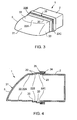
- la figure 3 est une vue en perspective d'un projecteur de véhicule automobile tel que représenté sur les figures 1 et 2, selon un mode de réalisation où il comporte une glace fusible ;
- la figure 4 est une vue schématique d'élévation en coupe du projecteur de la figure 3, où, pour des raisons de commodité, seuls sont représentés le boîtier et la glace du projecteur.
- Figure 1 is an elevational sectional view of a motor vehicle headlight according to the invention;
- Figure 2 is a view similar to Figure 1, according to an alternative embodiment;
- Figure 3 is a perspective view of a motor vehicle headlight as shown in Figures 1 and 2, according to an embodiment where it comprises a fusible glass;
- Figure 4 is a schematic sectional elevational view of the projector of Figure 3, where for convenience, only the housing and the mirror of the projector are shown.
Sur la figure 1 est représenté un projecteur 1 de véhicule automobile comportant un boîtier 2 renfermant un certain nombre de composants internes, parmi lesquels une source lumineuse 3 et un réflecteur 4 sur lequel est montée la source 3 dont il réfléchit et diffuse la lumière.In Figure 1 is shown a
Le projecteur 1 comporte également une glace 5 montée sur le boîtier 2, qu'elle referme à la manière d'un couvercle pour protéger les composants internes 3, 4 tout en transmettant la lumière émise par la source 3.The
La glace 5 délimite, conjointement avec le boîtier 2, un volume interne 6 dans lequel sont disposés les composants internes 3, 4. Dans le volume interne 6 est également disposé un masque 7 annulaire qui vient recouvrir le bord avant 8 du réflecteur 4 pour combler visuellement l'espace 9 entre celui-ci et le boîtier 2, et ainsi améliorer l'esthétique du projecteur 1.The
Comme on peut le voir sur la figure 1, le masque 7 comporte une portion externe annulaire 10 qui entoure le réflecteur 4, prolongée vers l'avant par une portion interne 11 sensiblement conique, recourbée vers l'arrière, qui chevauche le réflecteur 4. La portion externe 10 du masque 7 se termine, du côté opposé à la portion interne 11, par un bord arrière 12 tourné vers une paroi arrière 13 du boîtier 2.As can be seen in FIG. 1, the
De la sorte, outre son aspect décoratif, le masque 7, qui ne présente aucune arête tournée vers ia glace 5, protège un piéton des coupures dont il pourrait être victime en venant heurter, lors d'un choc avec le projecteur 1, le bord avant 8 du réflecteur 4.In this way, in addition to its decorative appearance, the
Afin d'optimiser la sécurité du piéton en cas de choc, le projecteur 1 comporte en outre des moyens déformables 14, interposés entre le masque 7 et le boîtier, et aptes à absorber au moins une partie de l'énergie d'un choc subi par le projecteur 1.In order to optimize the safety of the pedestrian in the event of an impact, the
Plus précisément, tel que représenté sur la figure 1, ces moyens déformables 14 comportent un élément 15 réalisé dans un matériau compressible, qui s'étend entre le bord arrière 12 du masque 7 et la paroi arrière 13 du boîtier 2.More precisely, as shown in FIG. 1, these deformable means 14 comprise an
Les moyens déformables 14 comportent un unique élément 15 annulaire, monobloc, réalisé dans une mousse, par exemple une mousse de polyuréthane et//ou en polypropylène expansé, et disposé au moins en partie (ici complètement) dans un logement complémentaire 16 ménagé dans le boîtier 2.The deformable means 14 comprise a single annular element, monobloc, made in a foam, for example a polyurethane foam and / or expanded polypropylene, and disposed at least partly (here completely) in a
Ce logement 16 est délimité, vers l'arrière, par la paroi arrière 13 du boîtier 2, vers l'extérieur, par une paroi externe 17 du boîtier et, vers l'intérieur, par une cloison 18 saillant de la paroi arrière 13 et concentrique à la paroi externe 17.This
Le logement 16 présente vers l'avant une ouverture 19 tournée vers la glace 5. Le bord arrière 12 du masque est 7 placé en face et à proximité immédiate de cette ouverture 19, refermant ainsi le logement 16.The
Lors d'un choc avec un obstacle, l'obstacle vient heurter la glace 5 qu'il repousse vers l'arrière. En se déformant, la glace 5 vient s'appuyer sur le masque 7 qui, en reculant, vient s'appuyer contre l'élément amortissant 15 qui se rétracte alors en absorbant une partie au moins de l'énergie du choc. On a donc une transmission de l'énergie du choc de la glace au masque puis du masque à l'élément amortissant. En l'occurrence, l'élément amortissant est guidé, lors de son recul, par son logement 16.During an impact with an obstacle, the obstacle hits the
Le logement 16 est optionnel, la tenue de l'élément 15 pouvant être réalisée par son introduction à force dans le boîtier 2. L'élément 15 peut par exemple présenter une section en forme de U, ce qui peut suffire à assurer sa tenue dans le boîtier 2.The
Par ailleurs, bien qu'un unique élément 15 soit ici prévu, il est envisageable d'en prévoir plusieurs, qui sont associés: par exemple en les superposant, ou en les disposant l'un derrière l'autre, ou côte à côte, notamment en fonction de l'espace disponible dans le projecteur 1.Furthermore, although a
La portion externe 10 du masque 7 pénètre alors dans le logement 16 où elle coulisse en repoussant l'élément compressible 15, le mouvement de recul du masque 7 étant ainsi guidé lors du choc.The
La déformation du projecteur 1 est donc contrôlée, de sorte que, lors du choc, le masque 7 recouvre en permanence le bord avant 8 du réflecteur 4.The deformation of the
Suivant une variante d'exécution, le masque 7 fait partie des moyens déformables 14. Ainsi, comme cela est représenté sur la figure 2, le masque 7 et l'élément compressible 15 ne forment qu'une seule et même pièce réalisée, dans un matériau compressible tel qu'une mousse de polyuréthane ou un polypropylène expansé, qui recouvre le bord avant 8 du réflecteur 4.According to an alternative embodiment, the
On peut aussi ne pas avoir de masque au sens habituel du terme.We can also not have a mask in the usual sense of the term.
Il en résulte une plus grande capacité d'absorption de l'énergie du choc, le masque 7 se déformant dans sa partie avant, dès que la glace 5 vient s'appuyer contre lui, puis dans sa partie arrière qui se trouve comprimée contre le boîtier 2.This results in a greater capacity for absorbing the energy of the shock, the
Par ailleurs, comme cela est représenté sur les figures 3 et 4, il est possible d'accroître la capacité d'absorption d'énergie du projecteur 1 à l'aide de moyens frangibles 20 prévus sur la glace 5, aptes à absorber, lors de leur rupture, au moins une partie de l'énergie d'un choc subi par le projecteur 1.Moreover, as shown in FIGS. 3 and 4, it is possible to increase the energy absorption capacity of the
La glace 5 comporte une paroi avant 21, bordée latéralement par une tranche 22 par laquelle la glace 5 est raccordée au boîtier 2. Plus précisément, la tranche 22 présente, à l'opposé de la paroi avant 21, un bord arrière 23 reçu dans une rainure 24 formée sur un bord avant 25 du boîtier 2.The
La tranche 22 de la glace 5 est déformable : elle comporte en effet au moins une zone de rupture prédéterminée formant les moyens frangibles 20 précités.The
En pratique, la tranche 22 de la glace 5 comporte au moins deux parties gigognes 22A, 22B, raccordées par une ligne de moindre épaisseur 20. Selon un mode de réalisation représenté sur les figures 2 et 3, trois parties gigognes successives 22A, 22B, 22C sont prévues, reliées deux à deux par une ligne de moindre épaisseur 20.In practice, the
Un choc frontal subi par le projecteur provoque le recul de la paroi avant 21, entraînant la rupture successive des lignes de moindre épaisseur 20, et l'emboîtement des parties gigognes 22A, 22B, 22C.A frontal impact suffered by the projector causes the recoil of the
Etant guidée dans son recul, la glace 5 se déforme de manière prédéterminée. Il en résulte une répartition uniforme de l'effort qu'elle communique au masque 7 lorsqu'elle vient le heurter après avoir déjà avoir absorbé une partie de l'énergie du choc. L'élément compressible 15 s'enfonce alors à son tour, de la manière décrite ci-dessus, en complétant l'absorption d'énergie du choc.Being guided in its recoil, the
Claims (10)
Applications Claiming Priority (2)
| Application Number | Priority Date | Filing Date | Title |
|---|---|---|---|
| FR0211705A FR2844754B1 (en) | 2002-09-20 | 2002-09-20 | MOTOR VEHICLE PROJECTOR COMPRISING DEFORMABLE MEANS FOR ABSORBING AT LEAST ONE PART OF THE ENERGY OF A SHOCK |
| EP03292271A EP1400406B1 (en) | 2002-09-20 | 2003-09-15 | Vehicle headlamp with means that can be distorted to absorb at least part of the energy from a choc |
Related Parent Applications (2)
| Application Number | Title | Priority Date | Filing Date |
|---|---|---|---|
| EP03292271.8 Division | 2003-09-15 | ||
| EP03292271A Division EP1400406B1 (en) | 2002-09-20 | 2003-09-15 | Vehicle headlamp with means that can be distorted to absorb at least part of the energy from a choc |
Publications (3)
| Publication Number | Publication Date |
|---|---|
| EP1780078A2 true EP1780078A2 (en) | 2007-05-02 |
| EP1780078A3 EP1780078A3 (en) | 2007-05-16 |
| EP1780078B1 EP1780078B1 (en) | 2011-04-20 |
Family
ID=31897513
Family Applications (2)
| Application Number | Title | Priority Date | Filing Date |
|---|---|---|---|
| EP06024685A Expired - Lifetime EP1780078B1 (en) | 2002-09-20 | 2003-09-15 | Vehicle headlamp with means that can be deformed to absorb at least part of the energy from an impact |
| EP03292271A Expired - Lifetime EP1400406B1 (en) | 2002-09-20 | 2003-09-15 | Vehicle headlamp with means that can be distorted to absorb at least part of the energy from a choc |
Family Applications After (1)
| Application Number | Title | Priority Date | Filing Date |
|---|---|---|---|
| EP03292271A Expired - Lifetime EP1400406B1 (en) | 2002-09-20 | 2003-09-15 | Vehicle headlamp with means that can be distorted to absorb at least part of the energy from a choc |
Country Status (5)
| Country | Link |
|---|---|
| EP (2) | EP1780078B1 (en) |
| AT (1) | ATE506223T1 (en) |
| DE (2) | DE60336860D1 (en) |
| ES (2) | ES2365351T3 (en) |
| FR (1) | FR2844754B1 (en) |
Cited By (1)
| Publication number | Priority date | Publication date | Assignee | Title |
|---|---|---|---|---|
| CN107696961A (en) * | 2017-09-27 | 2018-02-16 | 东风汽车公司 | The tail light for vehicle reinforcement structure and its manufacture method of anti-car body interference |
Families Citing this family (5)
| Publication number | Priority date | Publication date | Assignee | Title |
|---|---|---|---|---|
| FR2876068B1 (en) * | 2004-10-05 | 2006-12-15 | Valeo Vision Sa | ENERGY DAMPING PROJECTOR FOR MOTOR VEHICLE AND METHOD FOR ABSORBING ENERGY FROM PIECE SHOCK |
| FR2904277B1 (en) * | 2006-07-31 | 2009-05-15 | Valeo Vision Sa | PROJECTOR FOR MOTOR VEHICLE |
| DE102008057944A1 (en) * | 2008-11-19 | 2010-05-20 | Bayerische Motoren Werke Aktiengesellschaft | Headlight device for motor vehicle, has lamp which radiates light over light-reflecting surface of light reflector by translucent windshield, where upper front boundary area of light-reflecting surface is provided at distance from lamp |
| DE102008059611A1 (en) * | 2008-11-28 | 2010-06-02 | Audi Ag | Headlight for motor vehicle, has side wall sections made of plastic and connected by offset region, where offset range of sections corresponds to thickness of one of sections, and connection of sections form breaking point in region |
| FR3008046B1 (en) * | 2013-07-03 | 2016-10-28 | Peugeot Citroen Automobiles Sa | MOTOR VEHICLE PROJECTOR |
Citations (7)
| Publication number | Priority date | Publication date | Assignee | Title |
|---|---|---|---|---|
| EP1059200A2 (en) * | 1999-06-09 | 2000-12-13 | Hella KG Hueck & Co. | Headlamp |
| EP1120309A2 (en) * | 2000-01-28 | 2001-08-01 | Volkswagen Aktiengesellschaft | Headlight housing |
| US20010040811A1 (en) * | 1999-02-18 | 2001-11-15 | Chase Lee A. | Integrated flexible lamp assembly |
| US20010046140A1 (en) * | 1999-02-18 | 2001-11-29 | Chase Lee A. | Flexible lamp mounting |
| DE10101789A1 (en) * | 2001-01-17 | 2002-07-18 | Bosch Gmbh Robert | Illumination device, especially headlamp or lamp unit, for motor vehicles has preferred breakage point at which break occurs when shock load is applied to panel, enabling length reduction |
| EP1231108A1 (en) * | 2001-02-08 | 2002-08-14 | Faurecia Industries | Vehicle headlamp unit comprising improved lens fastening means |
| DE10143676A1 (en) * | 2001-09-06 | 2003-03-27 | Automotive Lighting Reutlingen | Vehicle headlamp absorbing crash energy, has front cover sliding back telescopically into headlamp casing, when acted on by force overcoming friction |
Family Cites Families (2)
| Publication number | Priority date | Publication date | Assignee | Title |
|---|---|---|---|---|
| FR2781736A1 (en) * | 1998-07-31 | 2000-02-04 | Plastic Omnium Cie | Optical illumination system for an automobile comprising breakaway mounting fixings permitting movement of the unit in the case of an impact |
| PL339627A1 (en) * | 1998-07-31 | 2001-01-02 | Plastic Omnium Cie | Optical systems for automotive vehicles |
-
2002
- 2002-09-20 FR FR0211705A patent/FR2844754B1/en not_active Expired - Fee Related
-
2003
- 2003-09-15 EP EP06024685A patent/EP1780078B1/en not_active Expired - Lifetime
- 2003-09-15 AT AT06024685T patent/ATE506223T1/en not_active IP Right Cessation
- 2003-09-15 EP EP03292271A patent/EP1400406B1/en not_active Expired - Lifetime
- 2003-09-15 DE DE60336860T patent/DE60336860D1/en not_active Expired - Lifetime
- 2003-09-15 ES ES06024685T patent/ES2365351T3/en not_active Expired - Lifetime
- 2003-09-15 ES ES03292271T patent/ES2280710T3/en not_active Expired - Lifetime
- 2003-09-15 DE DE60311204T patent/DE60311204T2/en not_active Expired - Lifetime
Patent Citations (7)
| Publication number | Priority date | Publication date | Assignee | Title |
|---|---|---|---|---|
| US20010040811A1 (en) * | 1999-02-18 | 2001-11-15 | Chase Lee A. | Integrated flexible lamp assembly |
| US20010046140A1 (en) * | 1999-02-18 | 2001-11-29 | Chase Lee A. | Flexible lamp mounting |
| EP1059200A2 (en) * | 1999-06-09 | 2000-12-13 | Hella KG Hueck & Co. | Headlamp |
| EP1120309A2 (en) * | 2000-01-28 | 2001-08-01 | Volkswagen Aktiengesellschaft | Headlight housing |
| DE10101789A1 (en) * | 2001-01-17 | 2002-07-18 | Bosch Gmbh Robert | Illumination device, especially headlamp or lamp unit, for motor vehicles has preferred breakage point at which break occurs when shock load is applied to panel, enabling length reduction |
| EP1231108A1 (en) * | 2001-02-08 | 2002-08-14 | Faurecia Industries | Vehicle headlamp unit comprising improved lens fastening means |
| DE10143676A1 (en) * | 2001-09-06 | 2003-03-27 | Automotive Lighting Reutlingen | Vehicle headlamp absorbing crash energy, has front cover sliding back telescopically into headlamp casing, when acted on by force overcoming friction |
Cited By (1)
| Publication number | Priority date | Publication date | Assignee | Title |
|---|---|---|---|---|
| CN107696961A (en) * | 2017-09-27 | 2018-02-16 | 东风汽车公司 | The tail light for vehicle reinforcement structure and its manufacture method of anti-car body interference |
Also Published As
| Publication number | Publication date |
|---|---|
| DE60311204D1 (en) | 2007-03-08 |
| FR2844754A1 (en) | 2004-03-26 |
| EP1400406A1 (en) | 2004-03-24 |
| ES2280710T3 (en) | 2007-09-16 |
| ES2365351T3 (en) | 2011-09-30 |
| FR2844754B1 (en) | 2005-05-27 |
| EP1400406B1 (en) | 2007-01-17 |
| EP1780078A3 (en) | 2007-05-16 |
| ATE506223T1 (en) | 2011-05-15 |
| EP1780078B1 (en) | 2011-04-20 |
| DE60311204T2 (en) | 2007-11-08 |
| DE60336860D1 (en) | 2011-06-01 |
Similar Documents
| Publication | Publication Date | Title |
|---|---|---|
| EP2254786B1 (en) | Motor vehicle rear module intended to be affixed to a rear hatch structure | |
| EP1400408B1 (en) | Headlamp for motor vehicle with improved connection means to vehicle chassis | |
| EP1400405B1 (en) | Headlamp comprising energy absorbing means | |
| EP2017123B1 (en) | Front face of an automobile vehicle comprising at least one window for an optical unit and a bumper. | |
| EP1736358A1 (en) | Headlamp for a vehicle | |
| EP1780078B1 (en) | Vehicle headlamp with means that can be deformed to absorb at least part of the energy from an impact | |
| EP1400407B1 (en) | Vehicle headlamp with an impact part | |
| EP1397284B1 (en) | Front end of a motor vehicle with integrated fittings | |
| EP3016820B1 (en) | Motor vehicle headlight | |
| EP2540572B1 (en) | Storage device including a front portion and a rear portion separable when exposed to a force | |
| FR2844753A1 (en) | Motor vehicle headlamp has front and rear housing components linked by shearing elements and fitted with impact shock absorbers | |
| EP1817212B1 (en) | Front panel comprising an impact protection device | |
| FR2900107A1 (en) | Motor vehicle headlight, has casing closing lighting unit e.g. LEDs, and electronic board that is integrally maintained against front side of wall by attachments, where portion carrying board is partly delimited by incipient crack zone | |
| EP1358084B9 (en) | Motor vehicle hatchback with a bumper structure | |
| EP1048521B1 (en) | Optical block mounting device on vehicle body parts | |
| EP1601558B1 (en) | Impact protection device for a front face of a motor vehicle | |
| FR2960496A1 (en) | Reflector housing for optical unit i.e. fog lamp, of vehicle i.e. automobile, has wall whose part is arranged so as to present internal face and frangible type structure allowing wall to be compressed on frangible type structure | |
| EP1147940B1 (en) | Vehicle headlamp mounted in potential impact region | |
| WO2010081949A1 (en) | Pedestrian impact absorber mobile knuckle mount | |
| EP1750972B1 (en) | Improved motor vehicle headlight | |
| EP3372478B1 (en) | Front panel part of a motor vehicle located in a collosion area integrated a rigid housing | |
| EP3381747A1 (en) | Device for attaching a headlight to a vehicle | |
| FR3083757A1 (en) | AIR GUIDE IN EXPANDED POLYMER MATERIAL WITH A SUPPORT AREA ON AN EXTREME FRONT CROSSING | |
| WO2006042999A1 (en) | Motor vehicle hood with a reinforced liner | |
| EP1669262A1 (en) | Car hood with absorbers |
Legal Events
| Date | Code | Title | Description |
|---|---|---|---|
| PUAI | Public reference made under article 153(3) epc to a published international application that has entered the european phase |
Free format text: ORIGINAL CODE: 0009012 |
|
| PUAL | Search report despatched |
Free format text: ORIGINAL CODE: 0009013 |
|
| AC | Divisional application: reference to earlier application |
Ref document number: 1400406 Country of ref document: EP Kind code of ref document: P |
|
| AK | Designated contracting states |
Kind code of ref document: A2 Designated state(s): AT BE BG CH CY CZ DE DK EE ES FI FR GB GR HU IE IT LI LU MC NL PT RO SE SI SK TR |
|
| AK | Designated contracting states |
Kind code of ref document: A3 Designated state(s): AT BE BG CH CY CZ DE DK EE ES FI FR GB GR HU IE IT LI LU MC NL PT RO SE SI SK TR |
|
| 17P | Request for examination filed |
Effective date: 20071024 |
|
| 17Q | First examination report despatched |
Effective date: 20071121 |
|
| AKX | Designation fees paid |
Designated state(s): AT BE BG CH CY CZ DE DK EE ES FI FR GB GR HU IE IT LI LU MC NL PT RO SE SI SK TR |
|
| GRAP | Despatch of communication of intention to grant a patent |
Free format text: ORIGINAL CODE: EPIDOSNIGR1 |
|
| RTI1 | Title (correction) |
Free format text: VEHICLE HEADLAMP WITH MEANS THAT CAN BE DEFORMED TO ABSORB AT LEAST PART OF THE ENERGY FROM AN IMPACT |
|
| GRAS | Grant fee paid |
Free format text: ORIGINAL CODE: EPIDOSNIGR3 |
|
| GRAA | (expected) grant |
Free format text: ORIGINAL CODE: 0009210 |
|
| AC | Divisional application: reference to earlier application |
Ref document number: 1400406 Country of ref document: EP Kind code of ref document: P |
|
| AK | Designated contracting states |
Kind code of ref document: B1 Designated state(s): AT BE BG CH CY CZ DE DK EE ES FI FR GB GR HU IE IT LI LU MC NL PT RO SE SI SK TR |
|
| REG | Reference to a national code |
Ref country code: GB Ref legal event code: FG4D Free format text: NOT ENGLISH |
|
| REG | Reference to a national code |
Ref country code: CH Ref legal event code: EP |
|
| REG | Reference to a national code |
Ref country code: IE Ref legal event code: FG4D Free format text: LANGUAGE OF EP DOCUMENT: FRENCH |
|
| REF | Corresponds to: |
Ref document number: 60336860 Country of ref document: DE Date of ref document: 20110601 Kind code of ref document: P |
|
| REG | Reference to a national code |
Ref country code: DE Ref legal event code: R096 Ref document number: 60336860 Country of ref document: DE Effective date: 20110601 |
|
| REG | Reference to a national code |
Ref country code: NL Ref legal event code: VDEP Effective date: 20110420 |
|
| REG | Reference to a national code |
Ref country code: ES Ref legal event code: FG2A Ref document number: 2365351 Country of ref document: ES Kind code of ref document: T3 Effective date: 20110930 |
|
| PG25 | Lapsed in a contracting state [announced via postgrant information from national office to epo] |
Ref country code: SE Free format text: LAPSE BECAUSE OF FAILURE TO SUBMIT A TRANSLATION OF THE DESCRIPTION OR TO PAY THE FEE WITHIN THE PRESCRIBED TIME-LIMIT Effective date: 20110420 Ref country code: PT Free format text: LAPSE BECAUSE OF FAILURE TO SUBMIT A TRANSLATION OF THE DESCRIPTION OR TO PAY THE FEE WITHIN THE PRESCRIBED TIME-LIMIT Effective date: 20110822 |
|
| REG | Reference to a national code |
Ref country code: IE Ref legal event code: FD4D |
|
| PG25 | Lapsed in a contracting state [announced via postgrant information from national office to epo] |
Ref country code: SI Free format text: LAPSE BECAUSE OF FAILURE TO SUBMIT A TRANSLATION OF THE DESCRIPTION OR TO PAY THE FEE WITHIN THE PRESCRIBED TIME-LIMIT Effective date: 20110420 Ref country code: FI Free format text: LAPSE BECAUSE OF FAILURE TO SUBMIT A TRANSLATION OF THE DESCRIPTION OR TO PAY THE FEE WITHIN THE PRESCRIBED TIME-LIMIT Effective date: 20110420 Ref country code: CY Free format text: LAPSE BECAUSE OF FAILURE TO SUBMIT A TRANSLATION OF THE DESCRIPTION OR TO PAY THE FEE WITHIN THE PRESCRIBED TIME-LIMIT Effective date: 20110420 Ref country code: GR Free format text: LAPSE BECAUSE OF FAILURE TO SUBMIT A TRANSLATION OF THE DESCRIPTION OR TO PAY THE FEE WITHIN THE PRESCRIBED TIME-LIMIT Effective date: 20110721 Ref country code: AT Free format text: LAPSE BECAUSE OF FAILURE TO SUBMIT A TRANSLATION OF THE DESCRIPTION OR TO PAY THE FEE WITHIN THE PRESCRIBED TIME-LIMIT Effective date: 20110420 |
|
| PG25 | Lapsed in a contracting state [announced via postgrant information from national office to epo] |
Ref country code: NL Free format text: LAPSE BECAUSE OF FAILURE TO SUBMIT A TRANSLATION OF THE DESCRIPTION OR TO PAY THE FEE WITHIN THE PRESCRIBED TIME-LIMIT Effective date: 20110420 |
|
| PG25 | Lapsed in a contracting state [announced via postgrant information from national office to epo] |
Ref country code: EE Free format text: LAPSE BECAUSE OF FAILURE TO SUBMIT A TRANSLATION OF THE DESCRIPTION OR TO PAY THE FEE WITHIN THE PRESCRIBED TIME-LIMIT Effective date: 20110420 Ref country code: IE Free format text: LAPSE BECAUSE OF FAILURE TO SUBMIT A TRANSLATION OF THE DESCRIPTION OR TO PAY THE FEE WITHIN THE PRESCRIBED TIME-LIMIT Effective date: 20110420 Ref country code: CZ Free format text: LAPSE BECAUSE OF FAILURE TO SUBMIT A TRANSLATION OF THE DESCRIPTION OR TO PAY THE FEE WITHIN THE PRESCRIBED TIME-LIMIT Effective date: 20110420 |
|
| PLBE | No opposition filed within time limit |
Free format text: ORIGINAL CODE: 0009261 |
|
| STAA | Information on the status of an ep patent application or granted ep patent |
Free format text: STATUS: NO OPPOSITION FILED WITHIN TIME LIMIT |
|
| PG25 | Lapsed in a contracting state [announced via postgrant information from national office to epo] |
Ref country code: DK Free format text: LAPSE BECAUSE OF FAILURE TO SUBMIT A TRANSLATION OF THE DESCRIPTION OR TO PAY THE FEE WITHIN THE PRESCRIBED TIME-LIMIT Effective date: 20110420 Ref country code: SK Free format text: LAPSE BECAUSE OF FAILURE TO SUBMIT A TRANSLATION OF THE DESCRIPTION OR TO PAY THE FEE WITHIN THE PRESCRIBED TIME-LIMIT Effective date: 20110420 Ref country code: RO Free format text: LAPSE BECAUSE OF FAILURE TO SUBMIT A TRANSLATION OF THE DESCRIPTION OR TO PAY THE FEE WITHIN THE PRESCRIBED TIME-LIMIT Effective date: 20110420 |
|
| 26N | No opposition filed |
Effective date: 20120123 |
|
| BERE | Be: lapsed |
Owner name: VALEO VISION Effective date: 20110930 |
|
| PG25 | Lapsed in a contracting state [announced via postgrant information from national office to epo] |
Ref country code: MC Free format text: LAPSE BECAUSE OF NON-PAYMENT OF DUE FEES Effective date: 20110930 |
|
| REG | Reference to a national code |
Ref country code: CH Ref legal event code: PL |
|
| REG | Reference to a national code |
Ref country code: DE Ref legal event code: R097 Ref document number: 60336860 Country of ref document: DE Effective date: 20120123 |
|
| GBPC | Gb: european patent ceased through non-payment of renewal fee |
Effective date: 20110915 |
|
| PG25 | Lapsed in a contracting state [announced via postgrant information from national office to epo] |
Ref country code: BE Free format text: LAPSE BECAUSE OF NON-PAYMENT OF DUE FEES Effective date: 20110930 |
|
| PG25 | Lapsed in a contracting state [announced via postgrant information from national office to epo] |
Ref country code: CH Free format text: LAPSE BECAUSE OF NON-PAYMENT OF DUE FEES Effective date: 20110930 Ref country code: LI Free format text: LAPSE BECAUSE OF NON-PAYMENT OF DUE FEES Effective date: 20110930 |
|
| PG25 | Lapsed in a contracting state [announced via postgrant information from national office to epo] |
Ref country code: GB Free format text: LAPSE BECAUSE OF NON-PAYMENT OF DUE FEES Effective date: 20110915 |
|
| PG25 | Lapsed in a contracting state [announced via postgrant information from national office to epo] |
Ref country code: LU Free format text: LAPSE BECAUSE OF NON-PAYMENT OF DUE FEES Effective date: 20110915 |
|
| PG25 | Lapsed in a contracting state [announced via postgrant information from national office to epo] |
Ref country code: BG Free format text: LAPSE BECAUSE OF FAILURE TO SUBMIT A TRANSLATION OF THE DESCRIPTION OR TO PAY THE FEE WITHIN THE PRESCRIBED TIME-LIMIT Effective date: 20110720 |
|
| PG25 | Lapsed in a contracting state [announced via postgrant information from national office to epo] |
Ref country code: TR Free format text: LAPSE BECAUSE OF FAILURE TO SUBMIT A TRANSLATION OF THE DESCRIPTION OR TO PAY THE FEE WITHIN THE PRESCRIBED TIME-LIMIT Effective date: 20110420 |
|
| PG25 | Lapsed in a contracting state [announced via postgrant information from national office to epo] |
Ref country code: HU Free format text: LAPSE BECAUSE OF FAILURE TO SUBMIT A TRANSLATION OF THE DESCRIPTION OR TO PAY THE FEE WITHIN THE PRESCRIBED TIME-LIMIT Effective date: 20110420 |
|
| PGFP | Annual fee paid to national office [announced via postgrant information from national office to epo] |
Ref country code: DE Payment date: 20140911 Year of fee payment: 12 |
|
| PGFP | Annual fee paid to national office [announced via postgrant information from national office to epo] |
Ref country code: ES Payment date: 20140919 Year of fee payment: 12 |
|
| PGFP | Annual fee paid to national office [announced via postgrant information from national office to epo] |
Ref country code: IT Payment date: 20140916 Year of fee payment: 12 |
|
| PGFP | Annual fee paid to national office [announced via postgrant information from national office to epo] |
Ref country code: FR Payment date: 20140930 Year of fee payment: 12 |
|
| REG | Reference to a national code |
Ref country code: DE Ref legal event code: R119 Ref document number: 60336860 Country of ref document: DE |
|
| PG25 | Lapsed in a contracting state [announced via postgrant information from national office to epo] |
Ref country code: IT Free format text: LAPSE BECAUSE OF NON-PAYMENT OF DUE FEES Effective date: 20150915 |
|
| REG | Reference to a national code |
Ref country code: FR Ref legal event code: ST Effective date: 20160531 |
|
| PG25 | Lapsed in a contracting state [announced via postgrant information from national office to epo] |
Ref country code: DE Free format text: LAPSE BECAUSE OF NON-PAYMENT OF DUE FEES Effective date: 20160401 |
|
| PG25 | Lapsed in a contracting state [announced via postgrant information from national office to epo] |
Ref country code: FR Free format text: LAPSE BECAUSE OF NON-PAYMENT OF DUE FEES Effective date: 20150930 |
|
| REG | Reference to a national code |
Ref country code: ES Ref legal event code: FD2A Effective date: 20161026 |
|
| PG25 | Lapsed in a contracting state [announced via postgrant information from national office to epo] |
Ref country code: ES Free format text: LAPSE BECAUSE OF NON-PAYMENT OF DUE FEES Effective date: 20150916 |