EP1780048A1 - Wheel for motorcycle and production method thereof - Google Patents
Wheel for motorcycle and production method thereof Download PDFInfo
- Publication number
- EP1780048A1 EP1780048A1 EP06255335A EP06255335A EP1780048A1 EP 1780048 A1 EP1780048 A1 EP 1780048A1 EP 06255335 A EP06255335 A EP 06255335A EP 06255335 A EP06255335 A EP 06255335A EP 1780048 A1 EP1780048 A1 EP 1780048A1
- Authority
- EP
- European Patent Office
- Prior art keywords
- section
- wheel
- spoke
- tubular section
- hub
- Prior art date
- Legal status (The legal status is an assumption and is not a legal conclusion. Google has not performed a legal analysis and makes no representation as to the accuracy of the status listed.)
- Granted
Links
- 238000004519 manufacturing process Methods 0.000 title claims abstract description 14
- 238000003754 machining Methods 0.000 claims abstract description 19
- 238000005266 casting Methods 0.000 claims description 17
- 238000004512 die casting Methods 0.000 claims description 9
- 229910052782 aluminium Inorganic materials 0.000 claims description 8
- XAGFODPZIPBFFR-UHFFFAOYSA-N aluminium Chemical compound [Al] XAGFODPZIPBFFR-UHFFFAOYSA-N 0.000 claims description 8
- FYYHWMGAXLPEAU-UHFFFAOYSA-N Magnesium Chemical compound [Mg] FYYHWMGAXLPEAU-UHFFFAOYSA-N 0.000 claims description 7
- 229910052749 magnesium Inorganic materials 0.000 claims description 7
- 239000011777 magnesium Substances 0.000 claims description 7
- 239000000463 material Substances 0.000 claims description 4
- 238000000034 method Methods 0.000 description 5
- 229910052751 metal Inorganic materials 0.000 description 2
- 239000002184 metal Substances 0.000 description 2
- 238000005452 bending Methods 0.000 description 1
- 238000005260 corrosion Methods 0.000 description 1
- 230000007797 corrosion Effects 0.000 description 1
- 238000005520 cutting process Methods 0.000 description 1
- 230000005855 radiation Effects 0.000 description 1
Images


Classifications
-
- B—PERFORMING OPERATIONS; TRANSPORTING
- B60—VEHICLES IN GENERAL
- B60B—VEHICLE WHEELS; CASTORS; AXLES FOR WHEELS OR CASTORS; INCREASING WHEEL ADHESION
- B60B1/00—Spoked wheels; Spokes thereof
-
- B—PERFORMING OPERATIONS; TRANSPORTING
- B60—VEHICLES IN GENERAL
- B60B—VEHICLE WHEELS; CASTORS; AXLES FOR WHEELS OR CASTORS; INCREASING WHEEL ADHESION
- B60B27/00—Hubs
- B60B27/02—Hubs adapted to be rotatably arranged on axle
-
- B—PERFORMING OPERATIONS; TRANSPORTING
- B60—VEHICLES IN GENERAL
- B60B—VEHICLE WHEELS; CASTORS; AXLES FOR WHEELS OR CASTORS; INCREASING WHEEL ADHESION
- B60B3/00—Disc wheels, i.e. wheels with load-supporting disc body
- B60B3/06—Disc wheels, i.e. wheels with load-supporting disc body formed by casting
Definitions
- the present invention relates to a wheel for a motorcycle whose hub includes an outer tubular section and an inner tubular section and which is intended to reduce weight by cutting down useless mass, and also relates to a production method of the wheel.
- a wheel is disclosed in JP-A-2000-280702 as a conventional wheel of this kind for a motorcycle.
- the wheel 100 for a motorcycle is formed with a rim section 101 to which a tire is mounted, a hub section 102 through which an axle extends, and a plurality of spoke sections 103 connecting the rim section 101 and the hub section 102 to each other.
- the hub section 102 is formed with an inner tubular section 110, an outer tubular section 111, and a connecting part 112 for connecting the inner and outer tubular sections to each other, and a space 113 is defined between the inner tubular section 110 and the outer tubular section 111.
- the wheel can reduce weight thereof by having the space 113.
- Bearing support surfaces 110a, 110b are formed on both sides of an inner circumferential surface of the inner tubular section 110.
- the bearing support surface 110a, 110b are formed by machining after the casting process of the wheel 100.
- auxiliary tubular member 114 a portion of the inner tubular section 110 is formed as a separate member called an auxiliary tubular member 114 to form a space 113 between the inner tubular section 110 and the outer tubular section 111 of the hub section 102.
- the auxiliary tubular member 114 needs to be disposed within a mold or a core is required to be placed to define the space 113, the casting process is troublesome.
- FIG. 14 shows another conventional art.
- a hub section 121 of a wheel 120 of this conventional art is constructed with an outer tubular section 122 formed in the wheel itself, one inner tubular section 123 formed in the wheel itself and the other inner tubular section 131 formed at a damper housing 130.
- Bearing support surfaces 123a, 131a are formed at respective inner circumferential surfaces of the pair of inner tubular sections 123, 131.
- the wheel 120 of the latter conventional art requires a machining process to form bolt holes 124 (damper housing attaching section) for attaching a damper housing 130 after the casting process.
- the damper housing 130 is then assembled after the machining process.
- a pair of bearing support surfaces 123a, 131a is need to be formed by machining respective inner circumferential surfaces of the inner tubular section 123 of the wheel 120 and the inner tubular section 131 of the damper housing 130.
- accurate positioning cannot be achieved.
- the present invention is made to solve the problem described above, and aims to provide a wheel of a motorcycle that can give superior production workability because of requiring only one machining to the wheel and also to provide a production method of the wheel.
- An aspect of the invention provides a wheel for a motorcycle comprising: a rim section to which a tire is mounted; a hub section including an outer tubular section and an inner tubular section, said both sections having lateral end openings through which an axle extends; and a plurality of spoke sections connecting said rim section and said hub section to each other, wherein a damper housing attaching section is provided to said outer tubular section of said hub section, and a bearing support surface is formed in an inner circumferential surface of said inner tubular section of said hub section.
- said inner tubular section of said hub section can have a projection projecting beyond an end of said outer tubular section in an axle direction, and a damper housing for enclosing a damper that attenuates drive force transmitted from an engine to the wheel is fitted in said projection.
- an opening area of one of the lateral side ends can be formed to be larger than that of the other lateral side end.
- a rib connecting the hub section and the rim section to each other can be formed in each one of the spoke sections.
- the rib can be formed at a leading edge portion and a trailing edge portion of the each one of the spoke sections relative to a rotational direction of the wheel along a width direction of the wheel.
- each one of the spoke sections can include a first spoke section and a second spoke section positioned next to each other, and the each one of the spoke sections can be connected to the hub section while the first spoke section and the second spoke section intersecting each other.
- first spoke section and the second spoke section intersect each other adjacent to a connecting portion thereof connecting to the hub section.
- each one of the spoke sections can extend in a tangential line direction of the outer tubular section of the hub section to be connected to the outer tubular section.
- a material of the wheel can be magnesium.
- the wheel can include a brake disk, wherein the brake disk can be assembled with an end of the outer tubular section via an aluminum plate.
- Another aspect of the invention provides a production method of a wheel for a motorcycle including: a casting process in which a rim section, a hub section including an inner tubular section and an outer tubular section, and a plurality of spoke sections are cast by die-casting to make a wheel cast body; and a machining process in which a damper housing attaching section is formed on the outer tubular section of the hub section of the wheel cast body, and a pair of bearing support surfaces are formed on both sides of an inner circumferential surface of the inner tubular section of the hub section.
- the rib can be formed at a leading edge portion and a trailing edge portion of each one of the spoke sections relative to a rotational direction of the wheel in a width direction of the wheel, and a distal end portion of the rib can be formed as a parting surface in the casting process.
- the wheel can be produced in the machining process to form the damper housing attaching section and the pair of bearing support surfaces to the wheel cast body produced in the casting process, and the damper housing can be assembled with the wheel.
- the machining processes can be made at one time and the production workability can be improved.
- FIGs. 1-12 show an example embodiment of a motorcycle to which a wheel of the present invention is applied.
- FIG. 1 is a side elevational view of the motorcycle.
- FIG. 2 is a right side elevational view of a rear wheel.
- FIG. 3 is a left side elevational view of the rear wheel.
- FIG. 4 is a cross sectional view taken along the line A-A of FIG. 2.
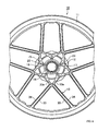
- FIG. 5 is a right side elevational view of a wheel body.
- FIG. 6 is a left side elevational view of the wheel body.
- FIG. 7 is a cross sectional view taken along the line B-B of FIG. 5.
- FIG. 8 is a cross sectional view taken along the line C-C of FIG. 7.
- FIG. 1 is a side elevational view of the motorcycle.
- FIG. 2 is a right side elevational view of a rear wheel.
- FIG. 3 is a left side elevational view of the rear wheel.
- FIG. 4 is a cross sectional view taken along the line A
- FIG. 9 is a cross sectional view for explaining a casting process.
- FIG. 10(a) is a cross sectional view showing a position of a parting surface of a cast metal mold.
- FIG. 10(b) is a cross sectional view showing an example in which the parting surface is positioned in the center in a width direction of the wheel body.
- FIG. 11 is a cross sectional view for explaining a machining process to the wheel body.
- FIG. 12 is a cross sectional view for explaining a process in which a damper housing is assembled with the wheel body.
- the motorcycle 1 includes a vehicle body 2, a front fork 3 and a rear arm 4 supported at front and rear positions of the vehicle body 2, respectively, and a front wheel 5 and a rear wheel 6, both of which wheels supported at respective distal ends of the front fork 3 and the rear arm 4.
- a wheel body 10 according to the present invention is applied to the rear wheel, and a structure of the rear wheel 6 will be described next.
- the wheel body 10 of the example embodiment of a rear wheel 6 is made by CF die-casting using a magnesium material.
- a tire 7 is mounted on the wheel body 10.
- the wheel body 10 includes an annular rim section 11, a hub section 12 through which an axle 8 extends and ten spoke sections 13 connecting the rim section 11 and the hub section 12 to each other.
- the hub section 12 is constructed with an inner tubular section 14, an outer tubular section 15, and a connecting section 16 for connecting both sections 15, 16 to each other.
- the inner tubular section 14 and the outer tubular section 15 have inclining cylindrical configurations which incline together in the same direction relative to an axial direction of the axle 8.
- respective inner and outer circumferential surfaces are formed to be surfaces defining a certain draft angle (approximately 1.5 degree).
- the inner and outer circumferential surfaces of the inner tubular section 14 and the outer tubular section 15 together form the draft angle (approximately 1.5 degree), and both of the inner tubular section 14 and the outer tubular section 15 are formed in such a manner that an opening area of one lateral side end is larger than that of the other lateral side end; thereby, the hub section 12 having the inner tubular section 14 and the outer tubular section 15 and having no useless or unnecessary mass existing between the inner tubular section 14 and the outer tubular section 15 can be produced by a die-casting method.
- the inner circumferential surfaces of the inner tubular section 14 on both sides thereof in the axle direction are formed as a pair of bearing support surfaces 17, 18.
- a needle bearing 20 is interposed between one bearing support surface 17 and the axle 8, while a ball bearing 21 is interposed between the other bearing support surface 18 and the axle 8.
- the wheel body 10 is supported by the axle 8 via the needle bearing 20 and the ball bearing 21 for rotation.
- damper housing 23 is put onto the projection 14a and is assembled with one end of the wheel 10 by being coupled with the outer tubular section 15 using bolts 24.
- a ball bearing 25 is interposed between the damper housing 23 and the axle 8 so that the damper housing 23, together with the wheel body 10, is supported for rotation relative to the axle 8 via the ball bearing 25.
- dampers 26 are supported at proper locations in the damper housing 23. Rotation from a side of a sprocket 27 is transmitted to the wheel body 10 via the multiple dampers 26.
- Several bolt holes 28 for attaching a brake disk are formed at the other end of the outer tubular section 15.
- the brake disk 29 is coupled with the outer tubular section 15 by a plurality of bolts 31 via one ring-shaped aluminum plate 30 to be assembled with the other end of the wheel body 10.
- Each spoke section 13 extends to the side of the rim section 11 in a tangential line direction of the hub section 12. As shown in FIG. 8, a cross sectional surface of each spoke section 13 is formed as the H-shape. Because of this H-shape, each spoke 13 has a pair of ribs 33, 34 formed on the front and reverse sides thereof. Also, a first spoke section 13a and a second spoke section 13b which are two spoke sections neighboring each other merge together at connecting portions thereof connecting to the hub section 12. In addition, the ribs 33 extend to the hub section 12 while intersecting one another at each connecting portion of the two spoke sections, i.e., the first spoke section 13a and the second spoke section 13b. Some of the ribs 33 positioned at the connecting portions are indicated by reference numeral 33a in the drawings to be clearly differed.
- a wheel cast body having a basic configuration of the wheel body 10 is formed by the CF die-casting method. That is, as shown in FIG. 9, using right and left molds 40, 41 and circumference molds 42, 42 which can be divided into four parts in the circumferential direction, the interior of a cavity 44 formed by the molds is vacuumed so as to be filled with molten magnesium. After the cavity is filled with the molten magnesium, the magnesium is cooled to a preset temperature to be solidified, resulting in a raw wheel body, followed by removing the right and left molds 40, 41 and the circumference molds 42, 42. In the embodiment, as shown in FIG.
- portions of the right and left molds 40, 41 for forming the spoke sections 13 are set to have parting surfaces 40a, 41 a existing at cavities 44a, 44b corresponding to distal end portions 35a, 35b of the respective ribs 33, 34 forming the H-shape.
- the wheel cast body is machined. That is, as shown in FIG. 11, both of end surfaces of the outer tubular section 15 of the hub section 12 are cut to be flat, and the bolt holes 22, 28 are formed at proper portions in both of the end surfaces. Also, the inner circumferential surfaces on both sides of the inner tubular section 14 are cut to be the bearing support surfaces 17, 18.
- the wheel body 10 has the bolt holes 22 functioning as the damper housing attaching section and formed in the outer tubular section 15 of the hub section 12, and the pair of bearing support surfaces 17, 18 are formed in the inner tubular section 14 of the hub section 12 and at the inner circumferential surfaces on both sides of the inner tubular section 14.
- all the things that need to be done are to machine the wheel cast body formed in the casting process to form the bolt holes 22 and the pair of bearing support surfaces 17, 18 so as to complete the wheel body 10, and to assemble the damper housing 23 with the wheel body 10 that has been completely machined.
- the machining processes for the wheel cast body can be made at once. That is, the machining processes for the wheel cast body can be made in one processing stage. The production workability thus can be improved.
- the inner tubular section 14 of the hub section 12 projects beyond the outer tubular section 15 in the axial direction and the damper housing 23 is fitted in the projected inner tubular section 14.
- the inner tubular section 14 and the outer tubular section 15 of the hub section 12 have the inclining cylindrical configurations which incline together in the same direction relative to the axial direction of the axle 8, and the respective inner and outer circumferential surfaces are formed to be surfaces defining the certain draft angle. Therefore, the hub section 12 having no useless mass can be prepared by die-casting.
- each spoke section 13 is formed as the H-shape and the H-shape makes it possible to form the pair of ribs on the front and reverse sides thereof.
- the hub section 12 having no useless mass thus can be produced by die-casting.
- each spoke section 13 has the pair of ribs 33, 34. The strength of the spoke 13 can be further improved.
- the two spoke sections 13 neighboring each other are merged at the connecting portion thereof connecting to the hub section 12, and the ribs 33a extend to the hub 12 while intersecting each other at the connecting portion.
- the strength of the spoke sections 13 thus can be extremely improved with little increase of weight.
- the spoke sections 13 extend in the tangential directions of the hub section 12, basically the bending stress does not act on the spoke sections 13 but mainly the compressive stress or tension stress act on them during braking or accelerating operation. Therefore, the concentrated stress is hardly generated. Accordingly, the spoke sections 13 can contribute to the design thereof to be light in weight.
- the wheel body 10 because the material of the wheel body 10 is magnesium, the wheel body 10 can be made to have light weight without spoiling the strength thereof in comparison with an aluminum wheel body.
- the brake disk 29 is assembled with the wheel body 10 via the one aluminum plate 30.
- the one aluminum plate 30 can avoid the electrical corrosion and is useful for improving accuracy, assuring flatness and avoiding mistakes in which the brake disk 29 is not assembled with. Further, radiation of heat from the brake disk 20 can be improved.
- the wheel body 10 is formed by a casting process in which a rim section 11, a hub section 12 including an inner tubular section 14 and an outer tubular section 15, and a plurality of spoke sections 13 are cast by die-casting to obtain a wheel cast body, and a machining process in which bolt holes 22, which is a damper housing attaching section, are formed on the outer tubular section 15 of the hub section 12 of the wheel cast body, and a pair of bearing support surfaces 17, 18 are formed on both sides of the inner circumferential surface of the inner tubular section 14 of the hub section 12.
- bolt holes 22, which is a damper housing attaching section are formed on the outer tubular section 15 of the hub section 12 of the wheel cast body, and a pair of bearing support surfaces 17, 18 are formed on both sides of the inner circumferential surface of the inner tubular section 14 of the hub section 12.
- each spoke section 13 has the H-shape
- the parting surfaces 40b, 41b for the casting process are made at the distal end portions 35a, 35b of the respective ribs 33, 34 forming the H-shape to have the casting process done. That is, as shown in FIG. 10(a), the right and left molds 40, 41 for forming the spoke section 13 have the parting surfaces 40a, 41b made at the cavities 44a, 44b forming the distal end portions 35a, 35b of the respective ribs 33, 34 so that a distance between the distal end portions 35a, 35b is separated more than a distance between base end portions or roots.
- the right half of the H-shape can be formed to have almost the same thickness.
- the thickness of the spoke section 13 needs to be tapered in the entire portions thereof in relation to the draft angle and the spoke section 13 cannot be formed evenly. Because of the reasons above, by setting the distal end portions 35a, 35b of the respective ribs 33, 34 to be the parting surfaces in this embodiment, the useless or unnecessary mass can be reduced and the extremely even spoke 13 can be produced. Accordingly, the spoke section 13 can be made light in weight.
- the wheel body 10 can be thinner and lighter.
- a wheel in which a rim section to which a tire is mounted, a hub section including an inner tubular section and an outer tubular section, and a plurality of spoke sections connecting the rim section and the hub section to each other are provided.
- Bolt holes can be provided to the outer tubular section 15 of the hub section for attaching a damper housing attaching section.
- a pair of bearing support surfaces can be formed in the inner tubular section of the hub section and on both ends of inner circumferential surfaces thereof.
Abstract
Description
- The present invention relates to a wheel for a motorcycle whose hub includes an outer tubular section and an inner tubular section and which is intended to reduce weight by cutting down useless mass, and also relates to a production method of the wheel.
- A wheel is disclosed in
JP-A-2000-280702 wheel 100 for a motorcycle is formed with arim section 101 to which a tire is mounted, ahub section 102 through which an axle extends, and a plurality ofspoke sections 103 connecting therim section 101 and thehub section 102 to each other. Thehub section 102 is formed with an innertubular section 110, an outertubular section 111, and a connectingpart 112 for connecting the inner and outer tubular sections to each other, and aspace 113 is defined between the innertubular section 110 and the outertubular section 111. The wheel can reduce weight thereof by having thespace 113.Bearing support surfaces tubular section 110. Thebearing support surface wheel 100. - Meanwhile, in the conventional art, a portion of the inner
tubular section 110 is formed as a separate member called an auxiliarytubular member 114 to form aspace 113 between the innertubular section 110 and the outertubular section 111 of thehub section 102. However, because the auxiliarytubular member 114 needs to be disposed within a mold or a core is required to be placed to define thespace 113, the casting process is troublesome. - On the other hand, FIG. 14 shows another conventional art. A
hub section 121 of awheel 120 of this conventional art is constructed with an outertubular section 122 formed in the wheel itself, one innertubular section 123 formed in the wheel itself and the other innertubular section 131 formed at adamper housing 130.Bearing support surfaces tubular sections - Because a
space 140 is defined between the innertubular section tubular section 122 of thehub section 121 in this latter conventional art, the reduction of weight can be realized similarly to the former conventional art. Also, because neither auxiliary tubular section nor core need to be placed within a mold, not similarly to the former conventional art, in the casting process of thewheel 120, the casting process is not troublesome. - However, the
wheel 120 of the latter conventional art requires a machining process to form bolt holes 124 (damper housing attaching section) for attaching adamper housing 130 after the casting process. Thedamper housing 130 is then assembled after the machining process. After the assembling of thedamper housing 130, a pair ofbearing support surfaces tubular section 123 of thewheel 120 and the innertubular section 131 of thedamper housing 130. Additionally, even if the inner circumferential surfaces of the respective innertubular sections wheel 120 and thedamper housing 130 are assembled together, accurate positioning cannot be achieved. - Because of the reasons discussed above, the latter conventional art requires machining process to be done twice. Accordingly, production workability is poor.
- Aspects of the invention are defined in the appended claims.
- The present invention is made to solve the problem described above, and aims to provide a wheel of a motorcycle that can give superior production workability because of requiring only one machining to the wheel and also to provide a production method of the wheel.
- An aspect of the invention provides a wheel for a motorcycle comprising: a rim section to which a tire is mounted; a hub section including an outer tubular section and an inner tubular section, said both sections having lateral end openings through which an axle extends; and a plurality of spoke sections connecting said rim section and said hub section to each other, wherein a damper housing attaching section is provided to said outer tubular section of said hub section, and a bearing support surface is formed in an inner circumferential surface of said inner tubular section of said hub section.
- In an embodiment, said inner tubular section of said hub section can have a projection projecting beyond an end of said outer tubular section in an axle direction, and a damper housing for enclosing a damper that attenuates drive force transmitted from an engine to the wheel is fitted in said projection.
- In an embodiment, as to the lateral side ends of either one of the inner tubular section and the outer tubular section, an opening area of one of the lateral side ends can be formed to be larger than that of the other lateral side end.
- In an embodiment, a rib connecting the hub section and the rim section to each other can be formed in each one of the spoke sections.
- In an embodiment, the rib can be formed at a leading edge portion and a trailing edge portion of the each one of the spoke sections relative to a rotational direction of the wheel along a width direction of the wheel.
- In an embodiment, the each one of the spoke sections can include a first spoke section and a second spoke section positioned next to each other, and the each one of the spoke sections can be connected to the hub section while the first spoke section and the second spoke section intersecting each other.
- In an embodiment, the first spoke section and the second spoke section intersect each other adjacent to a connecting portion thereof connecting to the hub section.
- In an embodiment, the each one of the spoke sections can extend in a tangential line direction of the outer tubular section of the hub section to be connected to the outer tubular section.
- In an embodiment, a material of the wheel can be magnesium.
- In an embodiment, the wheel can include a brake disk, wherein the brake disk can be assembled with an end of the outer tubular section via an aluminum plate.
- Another aspect of the invention provides a production method of a wheel for a motorcycle including: a casting process in which a rim section, a hub section including an inner tubular section and an outer tubular section, and a plurality of spoke sections are cast by die-casting to make a wheel cast body; and a machining process in which a damper housing attaching section is formed on the outer tubular section of the hub section of the wheel cast body, and a pair of bearing support surfaces are formed on both sides of an inner circumferential surface of the inner tubular section of the hub section.
- In an embodiment, the rib can be formed at a leading edge portion and a trailing edge portion of each one of the spoke sections relative to a rotational direction of the wheel in a width direction of the wheel, and a distal end portion of the rib can be formed as a parting surface in the casting process.
- In an embodiment of the invention, the wheel can be produced in the machining process to form the damper housing attaching section and the pair of bearing support surfaces to the wheel cast body produced in the casting process, and the damper housing can be assembled with the wheel. Thereby, the machining processes can be made at one time and the production workability can be improved.
- Example embodiments of the invention are described hereinafter with reference to the accompanying drawings in which:
- FIG. 1 illustrates a side elevational view of a motorcycle for an example embodiment of the present invention;
- FIG. 2 illustrates a right side elevational view of a rear wheel of an example embodiment of the present invention;
- FIG. 3 illustrates a left side elevational view of the rear wheel of the example embodiment;
- FIG. 4 is a cross sectional view along the line A-A of FIG. 2;
- FIG. 5 illustrates a right side elevational view of a wheel body of an example embodiment of the present invention;
- FIG. 6 illustrates a left side elevational view of the wheel body of an example embodiment of the present invention;
- FIG. 7 is a cross sectional view along the line B-B of FIG. 5;
- FIG. 8 is a cross sectional view along the line C-C of FIG. 7;
- FIG. 9 illustrates a cross sectional view for explaining a casting process for an example embodiment of the present invention;
- FIG. 10(a) is a cross sectional view showing a position of a parting surface of a cast metal mold.
- FIG. 10(b) is a cross sectional view showing an example in which the parting surface is positioned in the center in a width direction of the wheel body.
- FIG. 11 is a cross sectional view for explaining a machining process to the wheel body for an example embodiment of the present invention;
- FIG. 12 is a cross sectional view for explaining a process in which a damper housing is assembled with the wheel body for an example embodiment of the present invention;
- FIG. 13 is a cross sectional view of a conventional wheel body;
- FIG. 14 is a cross sectional view of another conventional wheel body and a damper housing.
- Hereunder, an example embodiment of the present invention will be described based upon the drawings. FIGs. 1-12 show an example embodiment of a motorcycle to which a wheel of the present invention is applied. FIG. 1 is a side elevational view of the motorcycle. FIG. 2 is a right side elevational view of a rear wheel. FIG. 3 is a left side elevational view of the rear wheel. FIG. 4 is a cross sectional view taken along the line A-A of FIG. 2. FIG. 5 is a right side elevational view of a wheel body. FIG. 6 is a left side elevational view of the wheel body. FIG. 7 is a cross sectional view taken along the line B-B of FIG. 5. FIG. 8 is a cross sectional view taken along the line C-C of FIG. 7. FIG. 9 is a cross sectional view for explaining a casting process. FIG. 10(a) is a cross sectional view showing a position of a parting surface of a cast metal mold. FIG. 10(b) is a cross sectional view showing an example in which the parting surface is positioned in the center in a width direction of the wheel body. FIG. 11 is a cross sectional view for explaining a machining process to the wheel body. FIG. 12 is a cross sectional view for explaining a process in which a damper housing is assembled with the wheel body.
- As shown in FIG. 1, the motorcycle 1 includes a vehicle body 2, a
front fork 3 and a rear arm 4 supported at front and rear positions of the vehicle body 2, respectively, and afront wheel 5 and arear wheel 6, both of which wheels supported at respective distal ends of thefront fork 3 and the rear arm 4. Awheel body 10 according to the present invention is applied to the rear wheel, and a structure of therear wheel 6 will be described next. - As shown in FIGs. 2-7, the
wheel body 10 of the example embodiment of arear wheel 6 is made by CF die-casting using a magnesium material. Atire 7 is mounted on thewheel body 10. Thewheel body 10 includes anannular rim section 11, ahub section 12 through which anaxle 8 extends and ten spokesections 13 connecting therim section 11 and thehub section 12 to each other. - The
hub section 12 is constructed with aninner tubular section 14, an outertubular section 15, and a connectingsection 16 for connecting bothsections inner tubular section 14 and the outertubular section 15 have inclining cylindrical configurations which incline together in the same direction relative to an axial direction of theaxle 8. In addition, respective inner and outer circumferential surfaces are formed to be surfaces defining a certain draft angle (approximately 1.5 degree). That is, the inner and outer circumferential surfaces of theinner tubular section 14 and the outertubular section 15 together form the draft angle (approximately 1.5 degree), and both of theinner tubular section 14 and the outertubular section 15 are formed in such a manner that an opening area of one lateral side end is larger than that of the other lateral side end; thereby, thehub section 12 having theinner tubular section 14 and the outertubular section 15 and having no useless or unnecessary mass existing between theinner tubular section 14 and the outertubular section 15 can be produced by a die-casting method. - The inner circumferential surfaces of the
inner tubular section 14 on both sides thereof in the axle direction are formed as a pair of bearing support surfaces 17, 18. Aneedle bearing 20 is interposed between one bearingsupport surface 17 and theaxle 8, while aball bearing 21 is interposed between the other bearingsupport surface 18 and theaxle 8. Thewheel body 10 is supported by theaxle 8 via theneedle bearing 20 and theball bearing 21 for rotation. - Several bolt holes 22 which provide a damper housing attaching section are formed at one end of the outer
tubular section 15. Also, aprojection 14a projecting outside in an axial direction thereof beyond the outertubular section 15 is formed at one end of theinner tubular section 14. Thedamper housing 23 is put onto theprojection 14a and is assembled with one end of thewheel 10 by being coupled with the outertubular section 15 usingbolts 24. Aball bearing 25 is interposed between thedamper housing 23 and theaxle 8 so that thedamper housing 23, together with thewheel body 10, is supported for rotation relative to theaxle 8 via theball bearing 25. In addition,dampers 26 are supported at proper locations in thedamper housing 23. Rotation from a side of asprocket 27 is transmitted to thewheel body 10 via themultiple dampers 26. - Several bolt holes 28 for attaching a brake disk are formed at the other end of the outer
tubular section 15. Thebrake disk 29 is coupled with the outertubular section 15 by a plurality ofbolts 31 via one ring-shapedaluminum plate 30 to be assembled with the other end of thewheel body 10. - Each spoke
section 13 extends to the side of therim section 11 in a tangential line direction of thehub section 12. As shown in FIG. 8, a cross sectional surface of each spokesection 13 is formed as the H-shape. Because of this H-shape, each spoke 13 has a pair ofribs first spoke section 13a and asecond spoke section 13b which are two spoke sections neighboring each other merge together at connecting portions thereof connecting to thehub section 12. In addition, theribs 33 extend to thehub section 12 while intersecting one another at each connecting portion of the two spoke sections, i.e., thefirst spoke section 13a and thesecond spoke section 13b. Some of theribs 33 positioned at the connecting portions are indicated byreference numeral 33a in the drawings to be clearly differed. - Next, production processes of the
wheel body 10 will be described. First, a wheel cast body having a basic configuration of thewheel body 10 is formed by the CF die-casting method. That is, as shown in FIG. 9, using right and leftmolds circumference molds cavity 44 formed by the molds is vacuumed so as to be filled with molten magnesium. After the cavity is filled with the molten magnesium, the magnesium is cooled to a preset temperature to be solidified, resulting in a raw wheel body, followed by removing the right and leftmolds circumference molds molds spoke sections 13 are set to haveparting surfaces cavities distal end portions respective ribs - Next, the wheel cast body is machined. That is, as shown in FIG. 11, both of end surfaces of the outer
tubular section 15 of thehub section 12 are cut to be flat, and the bolt holes 22, 28 are formed at proper portions in both of the end surfaces. Also, the inner circumferential surfaces on both sides of theinner tubular section 14 are cut to be the bearing support surfaces 17, 18. - Next, an assembling process in which the respective components are assembled with the
wheel body 10 is made. That is, as shown in FIG. 12, thedamper housing 23 is fitted in the one side of theinner tubular section 14 of thehub section 12, and thedamper housing 23, which is fitted in, is assembled by themultiple bolts 24. Also, thebrake disk 29 is placed on the other side of thehub section 12 via thealuminum plate 30 and thebrake disk 29 is assembled by themultiple bolts 31. - As thus described, the
wheel body 10 has the bolt holes 22 functioning as the damper housing attaching section and formed in the outertubular section 15 of thehub section 12, and the pair of bearing support surfaces 17, 18 are formed in theinner tubular section 14 of thehub section 12 and at the inner circumferential surfaces on both sides of theinner tubular section 14. Thus, all the things that need to be done are to machine the wheel cast body formed in the casting process to form the bolt holes 22 and the pair of bearing support surfaces 17, 18 so as to complete thewheel body 10, and to assemble thedamper housing 23 with thewheel body 10 that has been completely machined. Thereby, the machining processes for the wheel cast body can be made at once. That is, the machining processes for the wheel cast body can be made in one processing stage. The production workability thus can be improved. - In the embodiment, the
inner tubular section 14 of thehub section 12 projects beyond the outertubular section 15 in the axial direction and thedamper housing 23 is fitted in the projected innertubular section 14. Thus, the positioning work and the assembling work of thedamper housing 23 to thewheel body 10 can be easily made. - In the embodiment, the
inner tubular section 14 and the outertubular section 15 of thehub section 12 have the inclining cylindrical configurations which incline together in the same direction relative to the axial direction of theaxle 8, and the respective inner and outer circumferential surfaces are formed to be surfaces defining the certain draft angle. Therefore, thehub section 12 having no useless mass can be prepared by die-casting. - In the embodiment, the cross sectional surface of each spoke
section 13 is formed as the H-shape and the H-shape makes it possible to form the pair of ribs on the front and reverse sides thereof. Thehub section 12 having no useless mass thus can be produced by die-casting. Also, because of the H-shape, each spokesection 13 has the pair ofribs spoke 13 can be further improved. - In the embodiment, the two spoke
sections 13 neighboring each other are merged at the connecting portion thereof connecting to thehub section 12, and theribs 33a extend to thehub 12 while intersecting each other at the connecting portion. The strength of thespoke sections 13 thus can be extremely improved with little increase of weight. - In the embodiment, because the
spoke sections 13 extend in the tangential directions of thehub section 12, basically the bending stress does not act on thespoke sections 13 but mainly the compressive stress or tension stress act on them during braking or accelerating operation. Therefore, the concentrated stress is hardly generated. Accordingly, thespoke sections 13 can contribute to the design thereof to be light in weight. - In the embodiment, because the material of the
wheel body 10 is magnesium, thewheel body 10 can be made to have light weight without spoiling the strength thereof in comparison with an aluminum wheel body. - In the embodiment, the
brake disk 29 is assembled with thewheel body 10 via the onealuminum plate 30. The onealuminum plate 30 can avoid the electrical corrosion and is useful for improving accuracy, assuring flatness and avoiding mistakes in which thebrake disk 29 is not assembled with. Further, radiation of heat from thebrake disk 20 can be improved. - In the embodiment, the
wheel body 10 is formed by a casting process in which arim section 11, ahub section 12 including aninner tubular section 14 and an outertubular section 15, and a plurality ofspoke sections 13 are cast by die-casting to obtain a wheel cast body, and a machining process in which bolt holes 22, which is a damper housing attaching section, are formed on the outertubular section 15 of thehub section 12 of the wheel cast body, and a pair of bearing support surfaces 17, 18 are formed on both sides of the inner circumferential surface of theinner tubular section 14 of thehub section 12. Thereby, the machining processes for thewheel body 10 can be made at once. That is, the machining processes for the wheel cast body can be made in one processing stage. The production workability thus can be improved. - In the embodiment, the cross sectional surface of each spoke
section 13 has the H-shape, the parting surfaces 40b, 41b for the casting process are made at thedistal end portions respective ribs molds spoke section 13 have the parting surfaces 40a, 41b made at thecavities distal end portions respective ribs distal end portions wheel body 10 passing through the center of the H-shape are given as the parting surfaces 40b, 41b, the thickness of thespoke section 13 needs to be tapered in the entire portions thereof in relation to the draft angle and thespoke section 13 cannot be formed evenly. Because of the reasons above, by setting thedistal end portions respective ribs spoke section 13 can be made light in weight. - In the embodiment, because the casting process is the CF-die casting, the
wheel body 10 can be thinner and lighter.
In order to provide for superior production workability for a wheel of a motorcycle by requiring only one machining to the wheel, there has been described a wheel in which a rim section to which a tire is mounted, a hub section including an inner tubular section and an outer tubular section, and a plurality of spoke sections connecting the rim section and the hub section to each other are provided. Bolt holes can be provided to the outertubular section 15 of the hub section for attaching a damper housing attaching section. A pair of bearing support surfaces can be formed in the inner tubular section of the hub section and on both ends of inner circumferential surfaces thereof. -
- 7:
- tire
- 8:
- axle
- 10:
- wheel body
- 11:
- rim section
- 12:
- hub section
- 13:
- spoke section
- 13a:
- first spoke section
- 13b:
- second spoke section
- 14:
- inner tubular section
- 15:
- outer tubular section
- 17, 18:
- bearing support surface
- 20:
- needle bearing (bearing)
- 21:
- ball bearing (bearing)
- 22:
- bolt holes (damper housing attaching section)
- 23:
- damper housing
- 29:
- brake disk
- 30:
- aluminum plate
- 33, 33a, 34:
- rib
- 35a, 35b:
- distal portion of the rib
Claims (12)
- A wheel for a motorcycle comprising: a rim section to which a tire is mounted; a hub section including an outer tubular section and an inner tubular section, both said sections having lateral end openings through which an axle extends; and a plurality of spoke sections connecting said rim section and said hub section to each other, wherein
a damper housing attaching section is provided to said outer tubular section of said hub section, and
a bearing support surface is formed in an inner circumferential surface of said inner tubular section of said hub section. - The wheel for a motorcycle according to Claim 1, wherein
said inner tubular section of said hub section has a projection projecting beyond an end of said outer tubular section in an axle direction, and
a damper housing for enclosing a damper that attenuates drive force transmitted from an engine to the wheel is fitted in said projection. - The wheel for a motorcycle according to Claim 1 or Claim 2, wherein
with respect to the lateral side ends of either one of said inner tubular section and said outer tubular section, an opening area of one of the lateral side ends is formed to be larger than that of the other lateral side end. - The wheel for a motorcycle according to any preceding Claim, wherein
a rib connecting the hub section and the rim section to each other is formed in each one of said spoke sections. - The wheel for a motorcycle according to Claim 4, wherein
said rib is formed at a leading edge portion and a trailing edge portion of the each one of said spoke sections relative to a rotational direction of the wheel along a width direction of the wheel. - The wheel for a motorcycle according to Claim 4 or 5, wherein
the each one of said spoke sections includes a first spoke section and a second spoke section positioned next to each other, and
the each one of said spoke sections is connected to said hub section while said first spoke section and said second spoke section intersecting each other. - The wheel for a motorcycle according to Claim 6, wherein
said first spoke section and said second spoke section intersect each other adjacent to a connecting portion thereof connecting to said hub section. - The wheel for a motorcycle according to any preceding Claim, wherein
the each one of said spoke sections extends in a tangential line direction of said outer tubular section of said hub section to be connected to said outer tubular section. - The wheel for a motorcycle according to any preceding Claim, wherein
a material of the wheel is magnesium. - The wheel for a motorcycle according to Claim 9 comprising a brake disk, wherein
said brake disk is assembled with an end of said outer tubular section via an aluminum plate. - A production method of a wheel for a motorcycle comprising:a casting process in which a rim section, a hub section including an inner tubular section and an outer tubular section, and a plurality of spoke sections are cast by die-casting to make a wheel cast body; anda machining process in which a damper housing attaching section is formed on said outer tubular section of said hub section of said wheel cast body, and a pair of bearing support surfaces are formed on both sides of an inner circumferential surface of said inner tubular section of said hub section.
- The production method of a wheel for a motorcycle according to Claim 11, wherein
said rib is formed at a leading edge portion and a trailing edge portion of each one of said spoke sections relative to a rotational direction of the wheel in a width direction of the wheel, and
a distal end portion of said rib is formed as a parting surface in the casting process.
Applications Claiming Priority (1)
| Application Number | Priority Date | Filing Date | Title |
|---|---|---|---|
| JP2005311274A JP2007118684A (en) | 2005-10-26 | 2005-10-26 | Wheel of motorcycle and its manufacturing method |
Publications (2)
| Publication Number | Publication Date |
|---|---|
| EP1780048A1 true EP1780048A1 (en) | 2007-05-02 |
| EP1780048B1 EP1780048B1 (en) | 2010-07-28 |
Family
ID=37757103
Family Applications (1)
| Application Number | Title | Priority Date | Filing Date |
|---|---|---|---|
| EP06255335A Active EP1780048B1 (en) | 2005-10-26 | 2006-10-17 | Wheel for motorcycle and production method thereof |
Country Status (5)
| Country | Link |
|---|---|
| US (1) | US20070090685A1 (en) |
| EP (1) | EP1780048B1 (en) |
| JP (1) | JP2007118684A (en) |
| AT (1) | ATE475540T1 (en) |
| DE (1) | DE602006015754D1 (en) |
Cited By (4)
| Publication number | Priority date | Publication date | Assignee | Title |
|---|---|---|---|---|
| EP3199371A1 (en) * | 2015-02-10 | 2017-08-02 | Honda Motor Co., Ltd. | Wheel for straddle type vehicle |
| CN109501514A (en) * | 2017-09-15 | 2019-03-22 | 川崎重工业株式会社 | The wheel of automotive bicycle |
| DE102013222035B4 (en) * | 2012-11-06 | 2019-11-14 | Honda Motor Co., Ltd. | Wheel for a motorcycle |
| WO2021094028A1 (en) * | 2019-11-13 | 2021-05-20 | Bayerische Motoren Werke Aktiengesellschaft | Disk wheel for a motor vehicle and method for producing a disk wheel of this type |
Families Citing this family (6)
| Publication number | Priority date | Publication date | Assignee | Title |
|---|---|---|---|---|
| JP5733905B2 (en) * | 2010-03-31 | 2015-06-10 | 本田技研工業株式会社 | Motorcycle wheel structure |
| JP6100033B2 (en) * | 2013-03-08 | 2017-03-22 | 本田技研工業株式会社 | Vehicle wheel and method of manufacturing the same |
| JP6238336B2 (en) * | 2013-06-07 | 2017-11-29 | 本田技研工業株式会社 | Wheel for saddle riding type vehicle |
| ITMI20131775A1 (en) * | 2013-10-24 | 2015-04-25 | Ducati Motor Holding Spa | MOTORCYCLE WITH LATERAL SHOCK ABSORBER |
| JP2017217941A (en) | 2016-06-03 | 2017-12-14 | ヤマハ発動機株式会社 | Saddle-riding type vehicle |
| JP2020175792A (en) | 2019-04-19 | 2020-10-29 | ヤマハ発動機株式会社 | Die cast wheel and saddle-riding type vehicle |
Citations (4)
| Publication number | Priority date | Publication date | Assignee | Title |
|---|---|---|---|---|
| US4702527A (en) * | 1984-03-21 | 1987-10-27 | Honda Giken Kogyo Kabushiki Kaisha | Built-up wheel for vehicles |
| EP0754570A1 (en) * | 1995-07-18 | 1997-01-22 | Honda Giken Kogyo Kabushiki Kaisha | Cast wheel |
| JP2000280702A (en) | 1999-03-30 | 2000-10-10 | Honda Motor Co Ltd | Hollow casting structure |
| DE102004013489A1 (en) * | 2003-03-19 | 2004-10-07 | Honda Motor Co., Ltd. | Wheel construction for motorcycle includes first bearing connected to side wall component by cylindrical outer casing surrounding inner casing |
Family Cites Families (1)
| Publication number | Priority date | Publication date | Assignee | Title |
|---|---|---|---|---|
| US6463994B1 (en) * | 1998-12-28 | 2002-10-15 | Hayes Lemmerz International, Inc. | Apparatus and method for gravity casting a motorcycle wheel |
-
2005
- 2005-10-26 JP JP2005311274A patent/JP2007118684A/en not_active Withdrawn
-
2006
- 2006-10-17 EP EP06255335A patent/EP1780048B1/en active Active
- 2006-10-17 DE DE602006015754T patent/DE602006015754D1/en active Active
- 2006-10-17 AT AT06255335T patent/ATE475540T1/en not_active IP Right Cessation
- 2006-10-24 US US11/552,483 patent/US20070090685A1/en not_active Abandoned
Patent Citations (4)
| Publication number | Priority date | Publication date | Assignee | Title |
|---|---|---|---|---|
| US4702527A (en) * | 1984-03-21 | 1987-10-27 | Honda Giken Kogyo Kabushiki Kaisha | Built-up wheel for vehicles |
| EP0754570A1 (en) * | 1995-07-18 | 1997-01-22 | Honda Giken Kogyo Kabushiki Kaisha | Cast wheel |
| JP2000280702A (en) | 1999-03-30 | 2000-10-10 | Honda Motor Co Ltd | Hollow casting structure |
| DE102004013489A1 (en) * | 2003-03-19 | 2004-10-07 | Honda Motor Co., Ltd. | Wheel construction for motorcycle includes first bearing connected to side wall component by cylindrical outer casing surrounding inner casing |
Cited By (4)
| Publication number | Priority date | Publication date | Assignee | Title |
|---|---|---|---|---|
| DE102013222035B4 (en) * | 2012-11-06 | 2019-11-14 | Honda Motor Co., Ltd. | Wheel for a motorcycle |
| EP3199371A1 (en) * | 2015-02-10 | 2017-08-02 | Honda Motor Co., Ltd. | Wheel for straddle type vehicle |
| CN109501514A (en) * | 2017-09-15 | 2019-03-22 | 川崎重工业株式会社 | The wheel of automotive bicycle |
| WO2021094028A1 (en) * | 2019-11-13 | 2021-05-20 | Bayerische Motoren Werke Aktiengesellschaft | Disk wheel for a motor vehicle and method for producing a disk wheel of this type |
Also Published As
| Publication number | Publication date |
|---|---|
| DE602006015754D1 (en) | 2010-09-09 |
| EP1780048B1 (en) | 2010-07-28 |
| US20070090685A1 (en) | 2007-04-26 |
| JP2007118684A (en) | 2007-05-17 |
| ATE475540T1 (en) | 2010-08-15 |
Similar Documents
| Publication | Publication Date | Title |
|---|---|---|
| EP1780048A1 (en) | Wheel for motorcycle and production method thereof | |
| CN106687302B (en) | Cast aluminum wheel | |
| JP7352678B2 (en) | Vehicle wheel discs, vehicle wheels including such wheel discs, and methods of producing such wheel discs and vehicle wheels | |
| US6325462B1 (en) | Motor vehicle wheel having hollow spokes | |
| JP3878500B2 (en) | Cast wheel for motorcycle | |
| JP5462523B2 (en) | Integrated structure of metal parts having different material components and manufacturing method thereof | |
| EP2447088B1 (en) | Hub manufacturing method and wheel provided with the hub | |
| JP4680729B2 (en) | Vehicle wheel | |
| JP3279886B2 (en) | Motorcycle cast wheel | |
| JP4276144B2 (en) | Motorcycle wheel and its manufacturing method | |
| US11471934B2 (en) | Method for producing a cast vehicle wheel | |
| JPS6192754A (en) | Casting wheel | |
| JP2022133836A (en) | Cast wheel for saddle-riding type vehicle and method for manufacture thereof | |
| JP3691788B2 (en) | Method of manufacturing a cast wheel for a motorcycle | |
| JP2000255202A (en) | Cast aluminum wheel and manufacture thereof | |
| JP3863662B2 (en) | Vehicle wheel | |
| EP3725540B1 (en) | Diecast wheel, wheel unit and straddled vehicle | |
| JP7311437B2 (en) | Vehicle wheel manufacturing method | |
| JPS6092101A (en) | Solid wheel for motor-cycle | |
| JPH0585101A (en) | Cast wheel | |
| JP3131822B2 (en) | Finishing method for cast wheels | |
| JPH05185171A (en) | Manufacture of suspension arm | |
| EP3456549B1 (en) | Motorcycle wheel | |
| JP3328054B2 (en) | Hub material for spoke wheels | |
| JP2006327351A (en) | Wheel for vehicle, and its manufacturing method |
Legal Events
| Date | Code | Title | Description |
|---|---|---|---|
| PUAI | Public reference made under article 153(3) epc to a published international application that has entered the european phase |
Free format text: ORIGINAL CODE: 0009012 |
|
| AK | Designated contracting states |
Kind code of ref document: A1 Designated state(s): AT BE BG CH CY CZ DE DK EE ES FI FR GB GR HU IE IS IT LI LT LU LV MC NL PL PT RO SE SI SK TR |
|
| AX | Request for extension of the european patent |
Extension state: AL BA HR MK YU |
|
| 17P | Request for examination filed |
Effective date: 20070418 |
|
| 17Q | First examination report despatched |
Effective date: 20070619 |
|
| AKX | Designation fees paid |
Designated state(s): AT BE BG CH CY CZ DE DK EE ES FI FR GB GR HU IE IS IT LI LT LU LV MC NL PL PT RO SE SI SK TR |
|
| GRAP | Despatch of communication of intention to grant a patent |
Free format text: ORIGINAL CODE: EPIDOSNIGR1 |
|
| GRAS | Grant fee paid |
Free format text: ORIGINAL CODE: EPIDOSNIGR3 |
|
| GRAA | (expected) grant |
Free format text: ORIGINAL CODE: 0009210 |
|
| AK | Designated contracting states |
Kind code of ref document: B1 Designated state(s): AT BE BG CH CY CZ DE DK EE ES FI FR GB GR HU IE IS IT LI LT LU LV MC NL PL PT RO SE SI SK TR |
|
| REG | Reference to a national code |
Ref country code: GB Ref legal event code: FG4D |
|
| REG | Reference to a national code |
Ref country code: CH Ref legal event code: EP |
|
| REG | Reference to a national code |
Ref country code: IE Ref legal event code: FG4D |
|
| REF | Corresponds to: |
Ref document number: 602006015754 Country of ref document: DE Date of ref document: 20100909 Kind code of ref document: P |
|
| REG | Reference to a national code |
Ref country code: NL Ref legal event code: VDEP Effective date: 20100728 |
|
| LTIE | Lt: invalidation of european patent or patent extension |
Effective date: 20100728 |
|
| PG25 | Lapsed in a contracting state [announced via postgrant information from national office to epo] |
Ref country code: LT Free format text: LAPSE BECAUSE OF FAILURE TO SUBMIT A TRANSLATION OF THE DESCRIPTION OR TO PAY THE FEE WITHIN THE PRESCRIBED TIME-LIMIT Effective date: 20100728 Ref country code: NL Free format text: LAPSE BECAUSE OF FAILURE TO SUBMIT A TRANSLATION OF THE DESCRIPTION OR TO PAY THE FEE WITHIN THE PRESCRIBED TIME-LIMIT Effective date: 20100728 Ref country code: AT Free format text: LAPSE BECAUSE OF FAILURE TO SUBMIT A TRANSLATION OF THE DESCRIPTION OR TO PAY THE FEE WITHIN THE PRESCRIBED TIME-LIMIT Effective date: 20100728 Ref country code: FI Free format text: LAPSE BECAUSE OF FAILURE TO SUBMIT A TRANSLATION OF THE DESCRIPTION OR TO PAY THE FEE WITHIN THE PRESCRIBED TIME-LIMIT Effective date: 20100728 |
|
| PG25 | Lapsed in a contracting state [announced via postgrant information from national office to epo] |
Ref country code: PL Free format text: LAPSE BECAUSE OF FAILURE TO SUBMIT A TRANSLATION OF THE DESCRIPTION OR TO PAY THE FEE WITHIN THE PRESCRIBED TIME-LIMIT Effective date: 20100728 Ref country code: IS Free format text: LAPSE BECAUSE OF FAILURE TO SUBMIT A TRANSLATION OF THE DESCRIPTION OR TO PAY THE FEE WITHIN THE PRESCRIBED TIME-LIMIT Effective date: 20101128 Ref country code: CY Free format text: LAPSE BECAUSE OF FAILURE TO SUBMIT A TRANSLATION OF THE DESCRIPTION OR TO PAY THE FEE WITHIN THE PRESCRIBED TIME-LIMIT Effective date: 20100728 Ref country code: BG Free format text: LAPSE BECAUSE OF FAILURE TO SUBMIT A TRANSLATION OF THE DESCRIPTION OR TO PAY THE FEE WITHIN THE PRESCRIBED TIME-LIMIT Effective date: 20101028 Ref country code: PT Free format text: LAPSE BECAUSE OF FAILURE TO SUBMIT A TRANSLATION OF THE DESCRIPTION OR TO PAY THE FEE WITHIN THE PRESCRIBED TIME-LIMIT Effective date: 20101129 Ref country code: SI Free format text: LAPSE BECAUSE OF FAILURE TO SUBMIT A TRANSLATION OF THE DESCRIPTION OR TO PAY THE FEE WITHIN THE PRESCRIBED TIME-LIMIT Effective date: 20100728 |
|
| PG25 | Lapsed in a contracting state [announced via postgrant information from national office to epo] |
Ref country code: SE Free format text: LAPSE BECAUSE OF FAILURE TO SUBMIT A TRANSLATION OF THE DESCRIPTION OR TO PAY THE FEE WITHIN THE PRESCRIBED TIME-LIMIT Effective date: 20100728 Ref country code: LV Free format text: LAPSE BECAUSE OF FAILURE TO SUBMIT A TRANSLATION OF THE DESCRIPTION OR TO PAY THE FEE WITHIN THE PRESCRIBED TIME-LIMIT Effective date: 20100728 Ref country code: BE Free format text: LAPSE BECAUSE OF FAILURE TO SUBMIT A TRANSLATION OF THE DESCRIPTION OR TO PAY THE FEE WITHIN THE PRESCRIBED TIME-LIMIT Effective date: 20100728 Ref country code: GR Free format text: LAPSE BECAUSE OF FAILURE TO SUBMIT A TRANSLATION OF THE DESCRIPTION OR TO PAY THE FEE WITHIN THE PRESCRIBED TIME-LIMIT Effective date: 20101029 |
|
| PG25 | Lapsed in a contracting state [announced via postgrant information from national office to epo] |
Ref country code: DK Free format text: LAPSE BECAUSE OF FAILURE TO SUBMIT A TRANSLATION OF THE DESCRIPTION OR TO PAY THE FEE WITHIN THE PRESCRIBED TIME-LIMIT Effective date: 20100728 |
|
| PG25 | Lapsed in a contracting state [announced via postgrant information from national office to epo] |
Ref country code: SK Free format text: LAPSE BECAUSE OF FAILURE TO SUBMIT A TRANSLATION OF THE DESCRIPTION OR TO PAY THE FEE WITHIN THE PRESCRIBED TIME-LIMIT Effective date: 20100728 Ref country code: EE Free format text: LAPSE BECAUSE OF FAILURE TO SUBMIT A TRANSLATION OF THE DESCRIPTION OR TO PAY THE FEE WITHIN THE PRESCRIBED TIME-LIMIT Effective date: 20100728 Ref country code: CZ Free format text: LAPSE BECAUSE OF FAILURE TO SUBMIT A TRANSLATION OF THE DESCRIPTION OR TO PAY THE FEE WITHIN THE PRESCRIBED TIME-LIMIT Effective date: 20100728 Ref country code: MC Free format text: LAPSE BECAUSE OF NON-PAYMENT OF DUE FEES Effective date: 20101031 Ref country code: IT Free format text: LAPSE BECAUSE OF FAILURE TO SUBMIT A TRANSLATION OF THE DESCRIPTION OR TO PAY THE FEE WITHIN THE PRESCRIBED TIME-LIMIT Effective date: 20100728 Ref country code: RO Free format text: LAPSE BECAUSE OF FAILURE TO SUBMIT A TRANSLATION OF THE DESCRIPTION OR TO PAY THE FEE WITHIN THE PRESCRIBED TIME-LIMIT Effective date: 20100728 |
|
| REG | Reference to a national code |
Ref country code: CH Ref legal event code: PL |
|
| PLBE | No opposition filed within time limit |
Free format text: ORIGINAL CODE: 0009261 |
|
| STAA | Information on the status of an ep patent application or granted ep patent |
Free format text: STATUS: NO OPPOSITION FILED WITHIN TIME LIMIT |
|
| PG25 | Lapsed in a contracting state [announced via postgrant information from national office to epo] |
Ref country code: ES Free format text: LAPSE BECAUSE OF FAILURE TO SUBMIT A TRANSLATION OF THE DESCRIPTION OR TO PAY THE FEE WITHIN THE PRESCRIBED TIME-LIMIT Effective date: 20101108 |
|
| 26N | No opposition filed |
Effective date: 20110429 |
|
| PG25 | Lapsed in a contracting state [announced via postgrant information from national office to epo] |
Ref country code: LI Free format text: LAPSE BECAUSE OF NON-PAYMENT OF DUE FEES Effective date: 20101031 Ref country code: CH Free format text: LAPSE BECAUSE OF NON-PAYMENT OF DUE FEES Effective date: 20101031 |
|
| REG | Reference to a national code |
Ref country code: DE Ref legal event code: R097 Ref document number: 602006015754 Country of ref document: DE Effective date: 20110429 |
|
| PG25 | Lapsed in a contracting state [announced via postgrant information from national office to epo] |
Ref country code: IE Free format text: LAPSE BECAUSE OF NON-PAYMENT OF DUE FEES Effective date: 20101017 |
|
| PG25 | Lapsed in a contracting state [announced via postgrant information from national office to epo] |
Ref country code: LU Free format text: LAPSE BECAUSE OF NON-PAYMENT OF DUE FEES Effective date: 20101017 Ref country code: HU Free format text: LAPSE BECAUSE OF FAILURE TO SUBMIT A TRANSLATION OF THE DESCRIPTION OR TO PAY THE FEE WITHIN THE PRESCRIBED TIME-LIMIT Effective date: 20110129 |
|
| PG25 | Lapsed in a contracting state [announced via postgrant information from national office to epo] |
Ref country code: TR Free format text: LAPSE BECAUSE OF FAILURE TO SUBMIT A TRANSLATION OF THE DESCRIPTION OR TO PAY THE FEE WITHIN THE PRESCRIBED TIME-LIMIT Effective date: 20100728 |
|
| REG | Reference to a national code |
Ref country code: FR Ref legal event code: PLFP Year of fee payment: 10 |
|
| REG | Reference to a national code |
Ref country code: FR Ref legal event code: PLFP Year of fee payment: 11 |
|
| REG | Reference to a national code |
Ref country code: FR Ref legal event code: PLFP Year of fee payment: 12 |
|
| REG | Reference to a national code |
Ref country code: FR Ref legal event code: PLFP Year of fee payment: 13 |
|
| P01 | Opt-out of the competence of the unified patent court (upc) registered |
Effective date: 20230527 |
|
| PGFP | Annual fee paid to national office [announced via postgrant information from national office to epo] |
Ref country code: GB Payment date: 20231020 Year of fee payment: 18 |
|
| PGFP | Annual fee paid to national office [announced via postgrant information from national office to epo] |
Ref country code: FR Payment date: 20231023 Year of fee payment: 18 Ref country code: DE Payment date: 20231020 Year of fee payment: 18 |