EP1779951A1 - Saw blade clamp device for an electric reciprocating saw - Google Patents
Saw blade clamp device for an electric reciprocating saw Download PDFInfo
- Publication number
- EP1779951A1 EP1779951A1 EP20060113551 EP06113551A EP1779951A1 EP 1779951 A1 EP1779951 A1 EP 1779951A1 EP 20060113551 EP20060113551 EP 20060113551 EP 06113551 A EP06113551 A EP 06113551A EP 1779951 A1 EP1779951 A1 EP 1779951A1
- Authority
- EP
- European Patent Office
- Prior art keywords
- channel
- retaining member
- saw blade
- pin
- blade
- Prior art date
- Legal status (The legal status is an assumption and is not a legal conclusion. Google has not performed a legal analysis and makes no representation as to the accuracy of the status listed.)
- Granted
Links
- 230000007423 decrease Effects 0.000 claims description 2
- 238000010001 crabbing Methods 0.000 abstract description 7
- 238000005520 cutting process Methods 0.000 description 7
- 230000001447 compensatory effect Effects 0.000 description 1
- 239000012141 concentrate Substances 0.000 description 1
- 230000005611 electricity Effects 0.000 description 1
- 230000037431 insertion Effects 0.000 description 1
- 238000003780 insertion Methods 0.000 description 1
- 230000003993 interaction Effects 0.000 description 1
- 239000000463 material Substances 0.000 description 1
- 230000008447 perception Effects 0.000 description 1
Images


Classifications
-
- B—PERFORMING OPERATIONS; TRANSPORTING
- B23—MACHINE TOOLS; METAL-WORKING NOT OTHERWISE PROVIDED FOR
- B23D—PLANING; SLOTTING; SHEARING; BROACHING; SAWING; FILING; SCRAPING; LIKE OPERATIONS FOR WORKING METAL BY REMOVING MATERIAL, NOT OTHERWISE PROVIDED FOR
- B23D51/00—Sawing machines or sawing devices working with straight blades, characterised only by constructional features of particular parts; Carrying or attaching means for tools, covered by this subclass, which are connected to a carrier at both ends
- B23D51/08—Sawing machines or sawing devices working with straight blades, characterised only by constructional features of particular parts; Carrying or attaching means for tools, covered by this subclass, which are connected to a carrier at both ends of devices for mounting straight saw blades or other tools
- B23D51/10—Sawing machines or sawing devices working with straight blades, characterised only by constructional features of particular parts; Carrying or attaching means for tools, covered by this subclass, which are connected to a carrier at both ends of devices for mounting straight saw blades or other tools for hand-held or hand-operated devices
-
- B—PERFORMING OPERATIONS; TRANSPORTING
- B27—WORKING OR PRESERVING WOOD OR SIMILAR MATERIAL; NAILING OR STAPLING MACHINES IN GENERAL
- B27B—SAWS FOR WOOD OR SIMILAR MATERIAL; COMPONENTS OR ACCESSORIES THEREFOR
- B27B19/00—Other reciprocating saws with power drive; Fret-saws
- B27B19/02—Saws with a power- driven blade chucked at both ends or at one end only, e.g. jig saws, scroll saws
-
- B—PERFORMING OPERATIONS; TRANSPORTING
- B27—WORKING OR PRESERVING WOOD OR SIMILAR MATERIAL; NAILING OR STAPLING MACHINES IN GENERAL
- B27B—SAWS FOR WOOD OR SIMILAR MATERIAL; COMPONENTS OR ACCESSORIES THEREFOR
- B27B19/00—Other reciprocating saws with power drive; Fret-saws
- B27B19/02—Saws with a power- driven blade chucked at both ends or at one end only, e.g. jig saws, scroll saws
- B27B19/09—Saws with a power- driven blade chucked at both ends or at one end only, e.g. jig saws, scroll saws portable
-
- Y—GENERAL TAGGING OF NEW TECHNOLOGICAL DEVELOPMENTS; GENERAL TAGGING OF CROSS-SECTIONAL TECHNOLOGIES SPANNING OVER SEVERAL SECTIONS OF THE IPC; TECHNICAL SUBJECTS COVERED BY FORMER USPC CROSS-REFERENCE ART COLLECTIONS [XRACs] AND DIGESTS
- Y10—TECHNICAL SUBJECTS COVERED BY FORMER USPC
- Y10T—TECHNICAL SUBJECTS COVERED BY FORMER US CLASSIFICATION
- Y10T83/00—Cutting
- Y10T83/929—Tool or tool with support
- Y10T83/9457—Joint or connection
- Y10T83/9473—For rectilinearly reciprocating tool
- Y10T83/9481—Tool is single element reciprocable along elongate cutting edge [e.g., saw blade, etc.]
Definitions
- This invention relates to a blade clamp device for a hand-held motor driven reciprocating saw.
- the invention is described herein with reference to jigsaws, but is not considered to be limited to this particular type of saw. Indeed, the blade clamp described below can equally find use on any other type of reciprocating saw.
- Blade clamp devices for reciprocating saws are well known in the art.
- the clamp is used to fix the saw blade to a reciprocating shaft of the saw.
- the shaft is driven by an electric motor through a gearbox which converts rotary motion of the motor rotor into linear motion.
- these types of saws comprise a body housing the motor thereby providing means by which the saw can be hand-held.
- the body of the jigsaw has a longitudinal axis which is generally in-line with the cut direction of the saw blade disposed in the clamp.
- the motor is generally powered by mains supplied electricity or rechargeable battery.
- clamping devices There are many types of clamping devices available for use on jigsaws. Typically the clamps fall into two categories, namely tool-operated clamps where a tool is required to fix and release the blade to or from the clamp, and tool-free clamps which can be operated by hand. Tool-free clamp devices are generally considered advantageous for jigsaws because the blade can be removed and replaced with relative ease and without the user having to put the tool down and/or find a clamp-release tool.
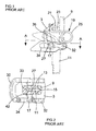
- a saw blade clamp comprises a body 3 and a releasable clamping device.
- the saw blade clamp is shown mounted to a reciprocating shaft 9 of a jigsaw (not shown).
- the saw blade 11 used for cutting workpieces is held in the clamp 1 by means of the releasable clamping device.
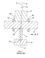
- the body 3 has a substantially T-shaped cross section, as shown in Figure 2.
- Three sides of a channel 13 are defined in the top of the T, the fourth side of the channel 13 being closed by the reciprocating shaft 9.
- the reciprocating shaft 9 includes a V-shaped longitudinal groove 15 which receives an edge of the saw blade 11 to assist in correctly aligning the saw blade 11 for cutting.
- the side of the channel 13 opposite to the V-shaped groove 15 is partially open to allow access to the saw blade 11 within the channel 13.
- a roller or pin 17 forming part of the releasable clamping device 5 can contact an edge of the saw blade 11.
- the pin 17 is carried by two torsion springs 19 which are mounted on either side of the channel 13.
- Each of the torsion springs 19 includes (i) a hooked end 21 engaging a seat 23 forming part of the body 3, (ii) a first helical portion 25 in torsion and (iii) a second helical portion 27 surrounding an end of the pin 17.
- the releasable clamping device 5 also includes a substantially U-shaped cross section release device 30.
- the release device is pivotably connected adjacent ends of the U to opposite surfaces of the body 3, one of which pivots is shown at 32.
- Each projection on the U comprises an elongate aperture 34 which slidably receives an end of the pin 17.
- the release device is provided with a colour which is easily distinguishable from the body of the clamping device, so that the device can be readily identified by a user of the jigsaw.
- the pin 17 is arranged to travel in a track 36 formed in the leg of the T-shaped body 3.
- the release device 30 which forms a lever, is pivoted upwards about the pivot 32, the pin 17 is moved away from the saw blade 11, thereby releasing the saw blade 11. Withdrawal of the saw blade 11 can then be affected.
- the torsion springs 19 urge the pin 17 downwards towards the channel 13 and into contact with the saw blade 11. Clamping or gripping of the saw blade 11 between the pin 17 and the reciprocating shaft 9 is thereby achieved to prevent removal of the saw blade 11 during use of the jigsaw.
- the pin 17 is provided with a circumferential groove 33 which receives the saw blade 11 to assist in aligning the saw blade 11 for cutting. Further, as a result of being cylindrical, the pin can roll along the edge of the saw blade 11 during clamping or release of the saw blade.
- this type of blade clamp has problems associated therewith; for instance, the pin can move laterally with respect to the reciprocating shaft during use. This lateral movement causes the blade to be misaligned to the longitudinal axis of the jigsaw body, which in turn causes the jigsaw to "crab".
- So-called crabbing occurs when the user has to off-set the alignment of the jigsaw's longitudinal axis with respect to the direction of cut of the blade in order to maintain a straight cut along the intended cut-line.
- a misaligned blade and hence the executed cut in a work piece
- Crabbing is undesirable because the user's perception of the direction in which the jigsaw is cutting can become confused.
- the user might have to concentrate on the job in hand, making constant adjustment to the alignment of the jigsaw's body in order to maintain a straight and accurate cut; the cutting action of a crabbing jigsaw can feel unnatural to the user.
- Figure 3 illustrates how misalignment of the blade axis to the blade clamp's body 3, and hence the reciprocating shaft 9, can cause crabbing.
- Figure 3 shows only those components of the blade clamp which are relevant for the illustration of crabbing and various components have been omitted for clarity reasons.
- the pin 17 is held in position by a washer 40, 40' and circlip 42, 42'.
- a degree of tolerance is required between the spacing of the circlips and the width of the clamp body in order to maintain fitment of the pin into the clamp track. As a result, the pin does not exactly fit the clamp body and lateral movement of the pin, as indicated by arrow A is possible.
- Figure 3 shows a situation where the pin is clamping a blade 11.
- the pin has moved to an extreme position within the confines on the circlip and washer arrangement such that the washer 40' on the left hand side is on engagement with the clamp body 3.
- the cut direction X of the blade 11 is not longer aligned to the axis Z of the clamp body (and hence the reciprocating shaft) by angle ⁇ .
- the jigsaw blade will wonder from the cut-line.
- the operator has to angle the jigsaw body thereby realigning the cut direction with the cut-line.
- the present invention aims to ameliorate the problems associated with the prior art.
- the present invention provides an electrically operated hand held reciprocating saw comprising, a motor housed in a housing, the motor having a drive spindle coupled to a gearbox arranged to convert rotary motion of the drive spindle into reciprocating motion of a gearbox shaft, and a blade clamp arranged for gripping a saw blade, wherein the blade clamp comprises a body defining a channel for accommodating a saw blade, and a pin carried by a spring mounted on the body, the spring being arranged to urge the pin towards an active position within the channel to retain a saw blade in the channel, and the pin comprises a groove arranged to engage with an edge of a saw blade; characterised in that a rear surface of the channel adjacent to the pin comprises an edge, a conduit or a rib arranged to engage with a protrusion or the groove disposed on the pin respectively.
- lateral movement of the pin is reduced or eliminated by the engagement and cooperation of the pin's protrusion or groove with
- the present invention also provides an electrically operated hand held reciprocating saw blade clamp comprising; a body defining a channel for accommodating a saw blade, and a pin carried by a spring mounted on the body, the spring being arranged to urge the pin towards an active position within the channel to retain a saw blade in the channel, and the pin comprises a groove arranged to engage with an edge of a saw blade; characterised in that a rear surface of the channel adjacent to the pin comprises an edge, a conduit or a rib arranged to engage with a protrusion or the groove disposed on the pin respectively.
- lateral movement of the pin is reduced or eliminated by the engagement of a feature of the pin with a component of the clamp body.
- the conduit has sidewalls angled by angle A with respect to a base portion of the conduit such that the width of the conduit decreases towards the base portion.
- the protrusion disposed on the pin comprises side sections angled by angle B with respect to longitudinal axis of the pin such that the width of the protrusion increases towards the pin.
- angle A is equal to angle B thereby resulting in a surface or line contact between the protrusion and the conduit. This can reduce wear of the protrusion as is moves against the walls of the conduit during blade clamping and releasing.
- this arrangement provides a means for seating the pin against the clamp body thereby preventing the pin from wobbling in the clamp.
- engagement of the protrusion and conduit prevents lateral movement of the pin in the channel, during use. Lateral movement could be minimised or eliminated with this arrangement.
- the pin is separated from the rear surface when protrusion engages with the conduit, during use thereby reducing or minimising wear of the pin during use.
- FIGs 4, 5 and 6 use the same numbers to indicate components shown in figure 1, 2 or 3 and which are common with the prior art.
- a blade clamp 100 embodying the present invention is shown.
- the clamp operates in a similar manner to the clamp described in EP792713A2 , at least insofar as the manual release mechanism and clamping principles are concerned.
- the blade retaining pin 110 and clamp body 112 have been redesigned to reduce or eliminate lateral pin movement with respect to the reciprocating shaft.
- the clamp body 112 comprises two surfaces, a front surface 113 which comprises a channel 117 running along the surface arranged to receive an edge of a cutting blade, and a rear surface 113' which comprises a groove 125 running along the surface arranged to receive a portion of the pin 110.
- the pin 110 comprises a longitudinal axis 114.
- a radial groove 116 for receiving and accommodating an edge of a blade 115, is formed in the centre portion of the pin.
- radial protrusions 120 and 122 are formed on either side of the groove 116. Each protrusion is arranged to have a peak and sloping surface 124 which meets the main body 118 of the pin 110.
- Each end 130 of the pin extends from the clamp body 112 and the ends of the pin 110 engage with a spring 19 and lever release mechanism 30 for operation of the clamp device 100. Furthermore, the pin runs in a slot in the clamp body during use, much the same as the prior art blade retaining pin arrangement.
- the sloping surfaces 124 of the pin 110 are arranged to engage and cooperate with side walls 126 of a conduit or channel 125 formed in the clamp body 112. Both of the sloping surface and side walls are angled by angles A and B, with respect to the longitudinal axis 114 of the pin and the base portion 127 of the channel 125 respectively.
- the base portion is arranged to be parallel with the longitudinal axis 114 of the pin 110.
- the pin locates itself in alignment with the blade and cut direction such that the longitudinal axis of the pin is perpendicular to the cut direction.
- the pin will naturally slot into the groove through the interaction and cooperation of the sloping surfaces and groove sidewalls.
- a force exerted by the spring urges the pin into the groove when a blade is disposed in the clamp body.
- the pin is arranged so that only the sloping surfaces contact the groove sidewalls during proper use; the main body 118 of the pin 110 is held away from the clamp body 112.
- the location of the pin within the clamp body is maintained with a relatively high degree of accuracy and the likelihood of lateral movement of the pin along its longitudinal axis is minimised or reduced.
- the blade is maintained in accurate alignment within the clamp body during cutting operations and crabbing caused by blade misalignment is minimised.
- the groove 116 and slot 117 of the clamp body in which the blade is accommodated are formed with generally V or U shaped cross-sections.
- V shaped cross-sections Alternatively, truncated V shaped cross-section might be used.
- the groove is triangular or trapezoidal in cross-section. This arranged can reduce stresses in associated parts during use.
- the pin should be made of hardened or tempered material to reduce the likelihood of groove 116 becoming worn by continued insertion and removal of a blade into the clamp 100. Such wear can result in the clamp force exerted on the blade reducing to an extent that the blade no longer remains clamped during operation of the saw.
- the protrusions 120 and 122 can be located further towards the ends 130 of the pin such that an edge of the clamp body, or the slot 36 in which the retaining pin is held, is engaged by the protrusions.
- the clamp body 112 might be arranged to include a ridge on its rear surface 127 to engage with the pin's groove 116, the edges of the ridge being arranged to engage with side walls of the groove.
- the slot 117 can be formed in the reciprocating shaft of the saw.
Landscapes
- Engineering & Computer Science (AREA)
- Mechanical Engineering (AREA)
- Life Sciences & Earth Sciences (AREA)
- Wood Science & Technology (AREA)
- Forests & Forestry (AREA)
- Sawing (AREA)
Abstract
Description
- This invention relates to a blade clamp device for a hand-held motor driven reciprocating saw. The invention is described herein with reference to jigsaws, but is not considered to be limited to this particular type of saw. Indeed, the blade clamp described below can equally find use on any other type of reciprocating saw.
- Blade clamp devices for reciprocating saws are well known in the art. The clamp is used to fix the saw blade to a reciprocating shaft of the saw. The shaft is driven by an electric motor through a gearbox which converts rotary motion of the motor rotor into linear motion. Typically these types of saws comprise a body housing the motor thereby providing means by which the saw can be hand-held. The body of the jigsaw has a longitudinal axis which is generally in-line with the cut direction of the saw blade disposed in the clamp. The motor is generally powered by mains supplied electricity or rechargeable battery.
- There are many types of clamping devices available for use on jigsaws. Typically the clamps fall into two categories, namely tool-operated clamps where a tool is required to fix and release the blade to or from the clamp, and tool-free clamps which can be operated by hand. Tool-free clamp devices are generally considered advantageous for jigsaws because the blade can be removed and replaced with relative ease and without the user having to put the tool down and/or find a clamp-release tool.
-
EP719610A1 EP792713A2 body 3 and a releasable clamping device. The saw blade clamp is shown mounted to a reciprocatingshaft 9 of a jigsaw (not shown). Thesaw blade 11 used for cutting workpieces is held in the clamp 1 by means of the releasable clamping device. - The
body 3 has a substantially T-shaped cross section, as shown in Figure 2. Three sides of achannel 13 are defined in the top of the T, the fourth side of thechannel 13 being closed by thereciprocating shaft 9. As can be seen in Figure 2, thereciprocating shaft 9 includes a V-shapedlongitudinal groove 15 which receives an edge of thesaw blade 11 to assist in correctly aligning thesaw blade 11 for cutting. - The side of the
channel 13 opposite to the V-shaped groove 15 is partially open to allow access to thesaw blade 11 within thechannel 13. Hence, a roller orpin 17 forming part of the releasable clamping device 5 can contact an edge of thesaw blade 11. Thepin 17 is carried by twotorsion springs 19 which are mounted on either side of thechannel 13. Each of thetorsion springs 19 includes (i) ahooked end 21 engaging aseat 23 forming part of thebody 3, (ii) a firsthelical portion 25 in torsion and (iii) a secondhelical portion 27 surrounding an end of thepin 17. - The releasable clamping device 5 also includes a substantially U-shaped cross
section release device 30. The release device is pivotably connected adjacent ends of the U to opposite surfaces of thebody 3, one of which pivots is shown at 32. Each projection on the U comprises anelongate aperture 34 which slidably receives an end of thepin 17. The release device is provided with a colour which is easily distinguishable from the body of the clamping device, so that the device can be readily identified by a user of the jigsaw. - As can be seen in Figure 1, the
pin 17 is arranged to travel in atrack 36 formed in the leg of the T-shaped body 3. Hence, if therelease device 30, which forms a lever, is pivoted upwards about thepivot 32, thepin 17 is moved away from thesaw blade 11, thereby releasing thesaw blade 11. Withdrawal of thesaw blade 11 can then be affected. Conversely, when the release device is released, the torsion springs 19 urge thepin 17 downwards towards thechannel 13 and into contact with thesaw blade 11. Clamping or gripping of thesaw blade 11 between thepin 17 and the reciprocatingshaft 9 is thereby achieved to prevent removal of thesaw blade 11 during use of the jigsaw. - As can be seen in Figure 2, the
pin 17 is provided with acircumferential groove 33 which receives thesaw blade 11 to assist in aligning thesaw blade 11 for cutting. Further, as a result of being cylindrical, the pin can roll along the edge of thesaw blade 11 during clamping or release of the saw blade. - However, this type of blade clamp has problems associated therewith; for instance, the pin can move laterally with respect to the reciprocating shaft during use. This lateral movement causes the blade to be misaligned to the longitudinal axis of the jigsaw body, which in turn causes the jigsaw to "crab".
- So-called crabbing occurs when the user has to off-set the alignment of the jigsaw's longitudinal axis with respect to the direction of cut of the blade in order to maintain a straight cut along the intended cut-line. In other words, if the user does not make a compensatory adjustment but maintains the jigsaw's longitudinal axis in alignment with the intended direction of cut, then a misaligned blade (and hence the executed cut in a work piece) wonders from the cut-line. Crabbing is undesirable because the user's perception of the direction in which the jigsaw is cutting can become confused. As a result, the user might have to concentrate on the job in hand, making constant adjustment to the alignment of the jigsaw's body in order to maintain a straight and accurate cut; the cutting action of a crabbing jigsaw can feel unnatural to the user.
- Figure 3 illustrates how misalignment of the blade axis to the blade clamp's
body 3, and hence thereciprocating shaft 9, can cause crabbing. Figure 3 shows only those components of the blade clamp which are relevant for the illustration of crabbing and various components have been omitted for clarity reasons. Thepin 17 is held in position by awasher 40, 40' andcirclip 42, 42'. A degree of tolerance is required between the spacing of the circlips and the width of the clamp body in order to maintain fitment of the pin into the clamp track. As a result, the pin does not exactly fit the clamp body and lateral movement of the pin, as indicated by arrow A is possible. - Figure 3 shows a situation where the pin is clamping a
blade 11. The pin has moved to an extreme position within the confines on the circlip and washer arrangement such that the washer 40' on the left hand side is on engagement with theclamp body 3. As a result, the cut direction X of theblade 11 is not longer aligned to the axis Z of the clamp body (and hence the reciprocating shaft) by angle α. Thus, the jigsaw blade will wonder from the cut-line. In order to compensate for this wondering, the operator has to angle the jigsaw body thereby realigning the cut direction with the cut-line. - The present invention aims to ameliorate the problems associated with the prior art. In summary, the present invention provides an electrically operated hand held reciprocating saw comprising, a motor housed in a housing, the motor having a drive spindle coupled to a gearbox arranged to convert rotary motion of the drive spindle into reciprocating motion of a gearbox shaft, and a blade clamp arranged for gripping a saw blade, wherein the blade clamp comprises a body defining a channel for accommodating a saw blade, and a pin carried by a spring mounted on the body, the spring being arranged to urge the pin towards an active position within the channel to retain a saw blade in the channel, and the pin comprises a groove arranged to engage with an edge of a saw blade; characterised in that a rear surface of the channel adjacent to the pin comprises an edge, a conduit or a rib arranged to engage with a protrusion or the groove disposed on the pin respectively. Thus, lateral movement of the pin is reduced or eliminated by the engagement and cooperation of the pin's protrusion or groove with a component of the clamp body.
- The present invention also provides an electrically operated hand held reciprocating saw blade clamp comprising; a body defining a channel for accommodating a saw blade, and a pin carried by a spring mounted on the body, the spring being arranged to urge the pin towards an active position within the channel to retain a saw blade in the channel, and the pin comprises a groove arranged to engage with an edge of a saw blade; characterised in that a rear surface of the channel adjacent to the pin comprises an edge, a conduit or a rib arranged to engage with a protrusion or the groove disposed on the pin respectively. Thus, lateral movement of the pin is reduced or eliminated by the engagement of a feature of the pin with a component of the clamp body.
- Preferably, the conduit has sidewalls angled by angle A with respect to a base portion of the conduit such that the width of the conduit decreases towards the base portion. The protrusion disposed on the pin comprises side sections angled by angle B with respect to longitudinal axis of the pin such that the width of the protrusion increases towards the pin. Preferably, angle A is equal to angle B thereby resulting in a surface or line contact between the protrusion and the conduit. This can reduce wear of the protrusion as is moves against the walls of the conduit during blade clamping and releasing. Furthermore, this arrangement provides a means for seating the pin against the clamp body thereby preventing the pin from wobbling in the clamp.
- Preferably, engagement of the protrusion and conduit prevents lateral movement of the pin in the channel, during use. Lateral movement could be minimised or eliminated with this arrangement.
- Preferably, the pin is separated from the rear surface when protrusion engages with the conduit, during use thereby reducing or minimising wear of the pin during use.
- An embodiment of the present invention is now described by way of example and with reference to the accompanying drawings, in which;
- Figure 1 shows a blade clamp known in the art;
- Figure 2 shows a cross-section of the blade clamp shown in figure 1 along line AA;
- Figure 3 shows, in schematic form, a cross-section of the blade clamp shown in figure 1;
- Figure 4 shows, in schematic form, a blade clamp embodying the present invention;
- Figure 5 shows, in schematic form, a cross-section along line BB of components of a blade clamp shown in figure 4; and
- Figure 6 shows, in schematic form, some components of the blade clamp of figure 4 and 5 embodying the present invention.
- Figures 4, 5 and 6 use the same numbers to indicate components shown in figure 1, 2 or 3 and which are common with the prior art.
- Referring to figure 4, a
blade clamp 100 embodying the present invention is shown. The clamp operates in a similar manner to the clamp described inEP792713A2 blade retaining pin 110 and clampbody 112 have been redesigned to reduce or eliminate lateral pin movement with respect to the reciprocating shaft. - Referring to figure 5 and 6 (figure 6 shows only some components of the clamp 100), the
clamp body 112 comprises two surfaces, afront surface 113 which comprises achannel 117 running along the surface arranged to receive an edge of a cutting blade, and a rear surface 113' which comprises agroove 125 running along the surface arranged to receive a portion of thepin 110. Thepin 110 comprises alongitudinal axis 114. Aradial groove 116, for receiving and accommodating an edge of ablade 115, is formed in the centre portion of the pin. On either side of thegroove 116,radial protrusions sloping surface 124 which meets themain body 118 of thepin 110. - Each
end 130 of the pin extends from theclamp body 112 and the ends of thepin 110 engage with aspring 19 andlever release mechanism 30 for operation of theclamp device 100. Furthermore, the pin runs in a slot in the clamp body during use, much the same as the prior art blade retaining pin arrangement. - The sloping
surfaces 124 of thepin 110 are arranged to engage and cooperate withside walls 126 of a conduit orchannel 125 formed in theclamp body 112. Both of the sloping surface and side walls are angled by angles A and B, with respect to thelongitudinal axis 114 of the pin and thebase portion 127 of thechannel 125 respectively. During use, the base portion is arranged to be parallel with thelongitudinal axis 114 of thepin 110. The angles A and B should be chosen such that A=B. Thus, during use, the pin's sloping surface contacts the side wall over an area, as opposed to a point contact. This advantageously results in lower wear rates of the pin's sloping surface and side walls. Furthermore, by arranging the sloping surfaces and side walls in this way, the pin locates itself in alignment with the blade and cut direction such that the longitudinal axis of the pin is perpendicular to the cut direction. In other words, the pin will naturally slot into the groove through the interaction and cooperation of the sloping surfaces and groove sidewalls. Further, a force exerted by the spring urges the pin into the groove when a blade is disposed in the clamp body. - The pin is arranged so that only the sloping surfaces contact the groove sidewalls during proper use; the
main body 118 of thepin 110 is held away from theclamp body 112. Thus, the location of the pin within the clamp body is maintained with a relatively high degree of accuracy and the likelihood of lateral movement of the pin along its longitudinal axis is minimised or reduced. As a result, the blade is maintained in accurate alignment within the clamp body during cutting operations and crabbing caused by blade misalignment is minimised. - Preferably, the
groove 116 and slot 117 of the clamp body in which the blade is accommodated are formed with generally V or U shaped cross-sections. Alternatively, truncated V shaped cross-section might be used. In other words, the groove is triangular or trapezoidal in cross-section. This arranged can reduce stresses in associated parts during use. The pin should be made of hardened or tempered material to reduce the likelihood ofgroove 116 becoming worn by continued insertion and removal of a blade into theclamp 100. Such wear can result in the clamp force exerted on the blade reducing to an extent that the blade no longer remains clamped during operation of the saw. - Alternative embodiments will be envisaged by the skilled person. For instance, the
protrusions ends 130 of the pin such that an edge of the clamp body, or theslot 36 in which the retaining pin is held, is engaged by the protrusions. Further still, theclamp body 112 might be arranged to include a ridge on itsrear surface 127 to engage with the pin'sgroove 116, the edges of the ridge being arranged to engage with side walls of the groove. Yet further still, theslot 117 can be formed in the reciprocating shaft of the saw.
Claims (8)
- An electrically operated hand held reciprocating saw comprising,
a motor housed in a housing, the motor having a drive spindle coupled to a gearbox arranged to convert rotary motion of the drive spindle into reciprocating motion of a shaft, and
a blade clamp disposed on the shaft and being arranged for gripping a saw blade,
wherein the blade clamp comprises
a body defining a channel for accommodating a saw blade, and
a retaining member coupled to a spring mounted on the body, the spring being arranged to urge the retaining member towards an active position in the channel to retain a saw blade in the channel,
the retaining member comprises a groove arranged to engage with an edge of a saw blade when a saw blade is disposed in the channel;
characterised in that a rear surface of the channel adjacent to the retaining member comprises a surface, such as channel or rib, arranged to engage with a protrusion disposed on the pin or the groove respectively during use. - An electrically operated hand held reciprocating saw blade clamp comprising;
a body defining a channel for accommodating a saw blade, and
a retaining member coupled to a spring mounted on the body, the spring being arranged to urge the retaining member towards an active position within the channel to retain a saw blade in the channel, and the retaining member comprises a groove arranged to engage with an edge of a saw blade;
characterised in that a rear surface of the channel adjacent to the retaining member comprises a conduit or rib arranged to engage with a protrusion or the groove disposed on the pin respectively. - A device according to claim 1 or 2, wherein the conduit has sidewalls angled by angle A with respect to a base portion of the conduit such that the width of the conduit decreases towards the base portion.
- A device according to claim 3, wherein the protrusion disposed on the retaining member comprises side sections angled by angle B with respect to longitudinal axis of the retaining member such that the width of the protrusion increases towards the retaining member.
- A device according to claim 4, wherein angle A is equal to angle B.
- A device according to claim 5, wherein engagement of the protrusion and conduit prevents lateral movement of the retaining member in the channel, during use.
- A device according to claim 1 or 2, wherein the retaining member is separated from the rear surface when protrusion engages with the conduit, during use.
- A device according to claim 1 or 2, wherein the groove has a triangular, or trapezoidal cross-section.
Applications Claiming Priority (1)
| Application Number | Priority Date | Filing Date | Title |
|---|---|---|---|
| GB0521932A GB2431613A (en) | 2005-10-28 | 2005-10-28 | Blade clamp for a reciprocating saw |
Publications (2)
| Publication Number | Publication Date |
|---|---|
| EP1779951A1 true EP1779951A1 (en) | 2007-05-02 |
| EP1779951B1 EP1779951B1 (en) | 2014-01-22 |
Family
ID=35515841
Family Applications (1)
| Application Number | Title | Priority Date | Filing Date |
|---|---|---|---|
| EP20060113551 Expired - Lifetime EP1779951B1 (en) | 2005-10-28 | 2006-05-05 | Saw blade clamp device for an electric reciprocating saw |
Country Status (5)
| Country | Link |
|---|---|
| US (1) | US7721450B2 (en) |
| EP (1) | EP1779951B1 (en) |
| CN (2) | CN1978111B (en) |
| AU (1) | AU2006202824B2 (en) |
| GB (1) | GB2431613A (en) |
Cited By (1)
| Publication number | Priority date | Publication date | Assignee | Title |
|---|---|---|---|---|
| TWI657883B (en) * | 2018-03-29 | 2019-05-01 | 王光彬 | Improved structure of saw handle |
Families Citing this family (8)
| Publication number | Priority date | Publication date | Assignee | Title |
|---|---|---|---|---|
| CN1788900B (en) * | 2005-12-13 | 2010-04-28 | 苏州宝时得电动工具有限公司 | Saw bit clamping device |
| US8813372B2 (en) | 2007-09-14 | 2014-08-26 | Milwaukee Electric Tool Corporation | Blade clamp mechanism |
| US8230607B2 (en) | 2008-05-09 | 2012-07-31 | Milwaukee Electric Tool Corporation | Keyless blade clamp for a power tool |
| DE102008001772A1 (en) * | 2008-05-14 | 2009-11-19 | Robert Bosch Gmbh | Machine tool, in particular hand-held machine tool |
| DE102008001756A1 (en) * | 2008-05-14 | 2009-11-19 | Robert Bosch Gmbh | Machine tool, in particular hand-held machine tool |
| AU2012202705B8 (en) | 2011-03-07 | 2014-11-06 | Infusion Brands, Inc. | Dual blade reciprocating saw |
| CN104551225B (en) * | 2013-10-28 | 2018-06-26 | 博世电动工具(中国)有限公司 | Saw blade clamping device and the sweep-saw for including this saw blade clamping device |
| CN104551521B (en) * | 2014-06-30 | 2017-01-11 | 哈尔滨汽轮机厂有限责任公司 | Special fixture for band saw blade staggered teeth |
Citations (4)
| Publication number | Priority date | Publication date | Assignee | Title |
|---|---|---|---|---|
| EP0792713A2 (en) * | 1996-03-01 | 1997-09-03 | Black & Decker Inc. | A saw blade clamp |
| JP2002326121A (en) * | 2001-04-26 | 2002-11-12 | Hitachi Koki Co Ltd | Reciprocating power tool |
| JP2002346829A (en) * | 2001-05-25 | 2002-12-04 | Ryobi Ltd | Device for clamping jigsaw blade |
| EP1649959A1 (en) * | 2004-10-22 | 2006-04-26 | GMCA PTY Ltd | Blade clamping apparatus |
Family Cites Families (15)
| Publication number | Priority date | Publication date | Assignee | Title |
|---|---|---|---|---|
| US2852874A (en) * | 1954-06-15 | 1958-09-23 | Electric Steel Foundry Co | Digger point and locking mechanism therefor |
| US3252721A (en) * | 1963-03-21 | 1966-05-24 | Anthony V Weasler | Slide lock for releasably connecting shaft elements |
| US3323816A (en) * | 1963-05-21 | 1967-06-06 | George C Meibuhr | Shaft collar assembly |
| US3698748A (en) * | 1972-02-28 | 1972-10-17 | Nello J Petri | Means for securing an insert to a base piece |
| US3952433A (en) * | 1974-09-03 | 1976-04-27 | Caterpillar Tractor Co. | Spring clip retaining means for earthworking tips |
| US4240204A (en) * | 1979-06-19 | 1980-12-23 | Black & Decker Inc. | Jig saw |
| US5199318A (en) * | 1991-11-22 | 1993-04-06 | Tecumseh Products Company | Device for restraining connecting rod on a crankshaft |
| US5765301A (en) * | 1996-08-05 | 1998-06-16 | H&L Tooth Company | Retention apparatus for a ground engaging tool |
| US6092958A (en) * | 1997-12-03 | 2000-07-25 | Caterpillar Inc. | Pin retainer for ground engaging tools |
| US6585458B1 (en) * | 1999-04-19 | 2003-07-01 | Filezall, Inc. | File adapter for power saw tool |
| JP4166982B2 (en) * | 2002-01-15 | 2008-10-15 | 日立工機株式会社 | Saver saw |
| GB2394692B (en) * | 2002-10-28 | 2005-08-17 | Black & Decker Inc | Support mechanism for reciprocating tool and tool incorporating such mechanism |
| US7234243B2 (en) * | 2003-06-25 | 2007-06-26 | Credo Technology Corporation | Reciprocating cutting tool with orbital action |
| CN2717591Y (en) * | 2004-02-05 | 2005-08-17 | 南京德朔实业有限公司 | Sweep-saw with lifting blade and rotating saw bit function |
| US7437824B2 (en) * | 2005-06-27 | 2008-10-21 | Black & Decker Inc. | Adjustable shoe assembly for a reciprocating saw |
-
2005
- 2005-10-28 GB GB0521932A patent/GB2431613A/en not_active Withdrawn
-
2006
- 2006-05-05 EP EP20060113551 patent/EP1779951B1/en not_active Expired - Lifetime
- 2006-07-04 AU AU2006202824A patent/AU2006202824B2/en not_active Ceased
- 2006-09-27 US US11/528,151 patent/US7721450B2/en not_active Expired - Fee Related
- 2006-10-20 CN CN2006101360404A patent/CN1978111B/en not_active Expired - Fee Related
- 2006-10-20 CN CN201110210764.XA patent/CN102275012B/en not_active Expired - Fee Related
Patent Citations (4)
| Publication number | Priority date | Publication date | Assignee | Title |
|---|---|---|---|---|
| EP0792713A2 (en) * | 1996-03-01 | 1997-09-03 | Black & Decker Inc. | A saw blade clamp |
| JP2002326121A (en) * | 2001-04-26 | 2002-11-12 | Hitachi Koki Co Ltd | Reciprocating power tool |
| JP2002346829A (en) * | 2001-05-25 | 2002-12-04 | Ryobi Ltd | Device for clamping jigsaw blade |
| EP1649959A1 (en) * | 2004-10-22 | 2006-04-26 | GMCA PTY Ltd | Blade clamping apparatus |
Cited By (1)
| Publication number | Priority date | Publication date | Assignee | Title |
|---|---|---|---|---|
| TWI657883B (en) * | 2018-03-29 | 2019-05-01 | 王光彬 | Improved structure of saw handle |
Also Published As
| Publication number | Publication date |
|---|---|
| CN102275012B (en) | 2015-08-26 |
| AU2006202824B2 (en) | 2011-09-15 |
| CN102275012A (en) | 2011-12-14 |
| GB2431613A (en) | 2007-05-02 |
| US7721450B2 (en) | 2010-05-25 |
| AU2006202824A1 (en) | 2007-05-17 |
| CN1978111B (en) | 2011-12-07 |
| EP1779951B1 (en) | 2014-01-22 |
| CN1978111A (en) | 2007-06-13 |
| GB0521932D0 (en) | 2005-12-07 |
| US20070101587A1 (en) | 2007-05-10 |
Similar Documents
| Publication | Publication Date | Title |
|---|---|---|
| EP0748665B1 (en) | A reciprocating saw blade clamp | |
| EP0949032B1 (en) | Saw blade clamp arrangement for a power tool | |
| EP0669181B1 (en) | Adjustable guide shoe for reciprocating saw | |
| US6009627A (en) | Saw blade clamping arrangement for a power tool | |
| US6920694B2 (en) | Saw with a tool guidance mechanism with guide elements adjustable to the tool size | |
| EP1435273B1 (en) | Clamp arrangement for receiving a saw blade in multiple orientations | |
| EP0792713B1 (en) | A saw blade clamp | |
| US8327550B2 (en) | Blade clamp for reciprocating saw | |
| EP3275582B1 (en) | Miter saw | |
| US7721450B2 (en) | Blade clamp for reciprocating saw | |
| CN101352769A (en) | Non-return device | |
| US20080222901A1 (en) | Hand-Guided Power Jigsaw | |
| US6502317B2 (en) | Blade ejection mechanism for a saw blade clamping arrangement of a power tool | |
| US5724742A (en) | Reciprocating saw blade clamp | |
| CN102271850A (en) | Jigsaw having a saw blade receptacle | |
| EP2591887A2 (en) | Electric power tool | |
| EP0719610A1 (en) | Saw blade clamp | |
| JPS59114002A (en) | Compass saw driven by motor | |
| US9283629B2 (en) | Handheld power saw | |
| GB2345461A (en) | Reciprocating saw blade provided with abrasive for scribing a workpiece | |
| GB2319987A (en) | Hand tool machine with a parallel guide |
Legal Events
| Date | Code | Title | Description |
|---|---|---|---|
| PUAI | Public reference made under article 153(3) epc to a published international application that has entered the european phase |
Free format text: ORIGINAL CODE: 0009012 |
|
| AK | Designated contracting states |
Kind code of ref document: A1 Designated state(s): AT BE BG CH CY CZ DE DK EE ES FI FR GB GR HU IE IS IT LI LT LU LV MC NL PL PT RO SE SI SK TR |
|
| AX | Request for extension of the european patent |
Extension state: AL BA HR MK YU |
|
| 17P | Request for examination filed |
Effective date: 20070517 |
|
| 17Q | First examination report despatched |
Effective date: 20070725 |
|
| AKX | Designation fees paid |
Designated state(s): AT BE BG CH CY CZ DE DK EE ES FI FR GB GR HU IE IS IT LI LT LU LV MC NL PL PT RO SE SI SK TR |
|
| GRAP | Despatch of communication of intention to grant a patent |
Free format text: ORIGINAL CODE: EPIDOSNIGR1 |
|
| INTG | Intention to grant announced |
Effective date: 20130826 |
|
| GRAS | Grant fee paid |
Free format text: ORIGINAL CODE: EPIDOSNIGR3 |
|
| GRAA | (expected) grant |
Free format text: ORIGINAL CODE: 0009210 |
|
| AK | Designated contracting states |
Kind code of ref document: B1 Designated state(s): AT BE BG CH CY CZ DE DK EE ES FI FR GB GR HU IE IS IT LI LT LU LV MC NL PL PT RO SE SI SK TR |
|
| REG | Reference to a national code |
Ref country code: GB Ref legal event code: FG4D |
|
| REG | Reference to a national code |
Ref country code: CH Ref legal event code: EP |
|
| REG | Reference to a national code |
Ref country code: AT Ref legal event code: REF Ref document number: 650537 Country of ref document: AT Kind code of ref document: T Effective date: 20140215 |
|
| REG | Reference to a national code |
Ref country code: IE Ref legal event code: FG4D |
|
| REG | Reference to a national code |
Ref country code: DE Ref legal event code: R096 Ref document number: 602006040145 Country of ref document: DE Effective date: 20140306 |
|
| REG | Reference to a national code |
Ref country code: NL Ref legal event code: VDEP Effective date: 20140122 |
|
| REG | Reference to a national code |
Ref country code: AT Ref legal event code: MK05 Ref document number: 650537 Country of ref document: AT Kind code of ref document: T Effective date: 20140122 |
|
| REG | Reference to a national code |
Ref country code: LT Ref legal event code: MG4D |
|
| PG25 | Lapsed in a contracting state [announced via postgrant information from national office to epo] |
Ref country code: LT Free format text: LAPSE BECAUSE OF FAILURE TO SUBMIT A TRANSLATION OF THE DESCRIPTION OR TO PAY THE FEE WITHIN THE PRESCRIBED TIME-LIMIT Effective date: 20140122 Ref country code: IS Free format text: LAPSE BECAUSE OF FAILURE TO SUBMIT A TRANSLATION OF THE DESCRIPTION OR TO PAY THE FEE WITHIN THE PRESCRIBED TIME-LIMIT Effective date: 20140522 |
|
| PG25 | Lapsed in a contracting state [announced via postgrant information from national office to epo] |
Ref country code: PT Free format text: LAPSE BECAUSE OF FAILURE TO SUBMIT A TRANSLATION OF THE DESCRIPTION OR TO PAY THE FEE WITHIN THE PRESCRIBED TIME-LIMIT Effective date: 20140522 Ref country code: CY Free format text: LAPSE BECAUSE OF FAILURE TO SUBMIT A TRANSLATION OF THE DESCRIPTION OR TO PAY THE FEE WITHIN THE PRESCRIBED TIME-LIMIT Effective date: 20140122 Ref country code: ES Free format text: LAPSE BECAUSE OF FAILURE TO SUBMIT A TRANSLATION OF THE DESCRIPTION OR TO PAY THE FEE WITHIN THE PRESCRIBED TIME-LIMIT Effective date: 20140122 Ref country code: FI Free format text: LAPSE BECAUSE OF FAILURE TO SUBMIT A TRANSLATION OF THE DESCRIPTION OR TO PAY THE FEE WITHIN THE PRESCRIBED TIME-LIMIT Effective date: 20140122 Ref country code: AT Free format text: LAPSE BECAUSE OF FAILURE TO SUBMIT A TRANSLATION OF THE DESCRIPTION OR TO PAY THE FEE WITHIN THE PRESCRIBED TIME-LIMIT Effective date: 20140122 Ref country code: NL Free format text: LAPSE BECAUSE OF FAILURE TO SUBMIT A TRANSLATION OF THE DESCRIPTION OR TO PAY THE FEE WITHIN THE PRESCRIBED TIME-LIMIT Effective date: 20140122 Ref country code: SE Free format text: LAPSE BECAUSE OF FAILURE TO SUBMIT A TRANSLATION OF THE DESCRIPTION OR TO PAY THE FEE WITHIN THE PRESCRIBED TIME-LIMIT Effective date: 20140122 |
|
| PG25 | Lapsed in a contracting state [announced via postgrant information from national office to epo] |
Ref country code: LV Free format text: LAPSE BECAUSE OF FAILURE TO SUBMIT A TRANSLATION OF THE DESCRIPTION OR TO PAY THE FEE WITHIN THE PRESCRIBED TIME-LIMIT Effective date: 20140122 Ref country code: BE Free format text: LAPSE BECAUSE OF FAILURE TO SUBMIT A TRANSLATION OF THE DESCRIPTION OR TO PAY THE FEE WITHIN THE PRESCRIBED TIME-LIMIT Effective date: 20140122 |
|
| REG | Reference to a national code |
Ref country code: DE Ref legal event code: R097 Ref document number: 602006040145 Country of ref document: DE |
|
| PG25 | Lapsed in a contracting state [announced via postgrant information from national office to epo] |
Ref country code: DK Free format text: LAPSE BECAUSE OF FAILURE TO SUBMIT A TRANSLATION OF THE DESCRIPTION OR TO PAY THE FEE WITHIN THE PRESCRIBED TIME-LIMIT Effective date: 20140122 Ref country code: CZ Free format text: LAPSE BECAUSE OF FAILURE TO SUBMIT A TRANSLATION OF THE DESCRIPTION OR TO PAY THE FEE WITHIN THE PRESCRIBED TIME-LIMIT Effective date: 20140122 Ref country code: RO Free format text: LAPSE BECAUSE OF FAILURE TO SUBMIT A TRANSLATION OF THE DESCRIPTION OR TO PAY THE FEE WITHIN THE PRESCRIBED TIME-LIMIT Effective date: 20140122 Ref country code: EE Free format text: LAPSE BECAUSE OF FAILURE TO SUBMIT A TRANSLATION OF THE DESCRIPTION OR TO PAY THE FEE WITHIN THE PRESCRIBED TIME-LIMIT Effective date: 20140122 |
|
| PG25 | Lapsed in a contracting state [announced via postgrant information from national office to epo] |
Ref country code: PL Free format text: LAPSE BECAUSE OF FAILURE TO SUBMIT A TRANSLATION OF THE DESCRIPTION OR TO PAY THE FEE WITHIN THE PRESCRIBED TIME-LIMIT Effective date: 20140122 Ref country code: SK Free format text: LAPSE BECAUSE OF FAILURE TO SUBMIT A TRANSLATION OF THE DESCRIPTION OR TO PAY THE FEE WITHIN THE PRESCRIBED TIME-LIMIT Effective date: 20140122 |
|
| PLBE | No opposition filed within time limit |
Free format text: ORIGINAL CODE: 0009261 |
|
| STAA | Information on the status of an ep patent application or granted ep patent |
Free format text: STATUS: NO OPPOSITION FILED WITHIN TIME LIMIT |
|
| 26N | No opposition filed |
Effective date: 20141023 |
|
| PG25 | Lapsed in a contracting state [announced via postgrant information from national office to epo] |
Ref country code: LU Free format text: LAPSE BECAUSE OF FAILURE TO SUBMIT A TRANSLATION OF THE DESCRIPTION OR TO PAY THE FEE WITHIN THE PRESCRIBED TIME-LIMIT Effective date: 20140505 |
|
| REG | Reference to a national code |
Ref country code: CH Ref legal event code: PL |
|
| PG25 | Lapsed in a contracting state [announced via postgrant information from national office to epo] |
Ref country code: LI Free format text: LAPSE BECAUSE OF NON-PAYMENT OF DUE FEES Effective date: 20140531 Ref country code: MC Free format text: LAPSE BECAUSE OF FAILURE TO SUBMIT A TRANSLATION OF THE DESCRIPTION OR TO PAY THE FEE WITHIN THE PRESCRIBED TIME-LIMIT Effective date: 20140122 Ref country code: CH Free format text: LAPSE BECAUSE OF NON-PAYMENT OF DUE FEES Effective date: 20140531 |
|
| REG | Reference to a national code |
Ref country code: DE Ref legal event code: R097 Ref document number: 602006040145 Country of ref document: DE Effective date: 20141023 |
|
| REG | Reference to a national code |
Ref country code: IE Ref legal event code: MM4A |
|
| REG | Reference to a national code |
Ref country code: FR Ref legal event code: ST Effective date: 20150130 |
|
| PG25 | Lapsed in a contracting state [announced via postgrant information from national office to epo] |
Ref country code: IE Free format text: LAPSE BECAUSE OF NON-PAYMENT OF DUE FEES Effective date: 20140505 |
|
| PG25 | Lapsed in a contracting state [announced via postgrant information from national office to epo] |
Ref country code: FR Free format text: LAPSE BECAUSE OF NON-PAYMENT OF DUE FEES Effective date: 20140602 Ref country code: SI Free format text: LAPSE BECAUSE OF FAILURE TO SUBMIT A TRANSLATION OF THE DESCRIPTION OR TO PAY THE FEE WITHIN THE PRESCRIBED TIME-LIMIT Effective date: 20140122 |
|
| PG25 | Lapsed in a contracting state [announced via postgrant information from national office to epo] |
Ref country code: BG Free format text: LAPSE BECAUSE OF FAILURE TO SUBMIT A TRANSLATION OF THE DESCRIPTION OR TO PAY THE FEE WITHIN THE PRESCRIBED TIME-LIMIT Effective date: 20140122 |
|
| PG25 | Lapsed in a contracting state [announced via postgrant information from national office to epo] |
Ref country code: GR Free format text: LAPSE BECAUSE OF FAILURE TO SUBMIT A TRANSLATION OF THE DESCRIPTION OR TO PAY THE FEE WITHIN THE PRESCRIBED TIME-LIMIT Effective date: 20140423 Ref country code: IT Free format text: LAPSE BECAUSE OF FAILURE TO SUBMIT A TRANSLATION OF THE DESCRIPTION OR TO PAY THE FEE WITHIN THE PRESCRIBED TIME-LIMIT Effective date: 20140122 |
|
| PG25 | Lapsed in a contracting state [announced via postgrant information from national office to epo] |
Ref country code: HU Free format text: LAPSE BECAUSE OF FAILURE TO SUBMIT A TRANSLATION OF THE DESCRIPTION OR TO PAY THE FEE WITHIN THE PRESCRIBED TIME-LIMIT; INVALID AB INITIO Effective date: 20060505 Ref country code: TR Free format text: LAPSE BECAUSE OF FAILURE TO SUBMIT A TRANSLATION OF THE DESCRIPTION OR TO PAY THE FEE WITHIN THE PRESCRIBED TIME-LIMIT Effective date: 20140122 |
|
| PGFP | Annual fee paid to national office [announced via postgrant information from national office to epo] |
Ref country code: DE Payment date: 20200422 Year of fee payment: 15 |
|
| PGFP | Annual fee paid to national office [announced via postgrant information from national office to epo] |
Ref country code: GB Payment date: 20200422 Year of fee payment: 15 |
|
| REG | Reference to a national code |
Ref country code: DE Ref legal event code: R119 Ref document number: 602006040145 Country of ref document: DE |
|
| GBPC | Gb: european patent ceased through non-payment of renewal fee |
Effective date: 20210505 |
|
| PG25 | Lapsed in a contracting state [announced via postgrant information from national office to epo] |
Ref country code: GB Free format text: LAPSE BECAUSE OF NON-PAYMENT OF DUE FEES Effective date: 20210505 Ref country code: DE Free format text: LAPSE BECAUSE OF NON-PAYMENT OF DUE FEES Effective date: 20211201 |