EP1779747A2 - Fastening element and detachable fastening system for prefabricated furniture or subassemblies - Google Patents
Fastening element and detachable fastening system for prefabricated furniture or subassemblies Download PDFInfo
- Publication number
- EP1779747A2 EP1779747A2 EP06022567A EP06022567A EP1779747A2 EP 1779747 A2 EP1779747 A2 EP 1779747A2 EP 06022567 A EP06022567 A EP 06022567A EP 06022567 A EP06022567 A EP 06022567A EP 1779747 A2 EP1779747 A2 EP 1779747A2
- Authority
- EP
- European Patent Office
- Prior art keywords
- connecting element
- furniture
- conical
- connection system
- releasable connection
- Prior art date
- Legal status (The legal status is an assumption and is not a legal conclusion. Google has not performed a legal analysis and makes no representation as to the accuracy of the status listed.)
- Withdrawn
Links
- 238000000465 moulding Methods 0.000 claims description 50
- 230000000087 stabilizing effect Effects 0.000 claims description 13
- 230000000712 assembly Effects 0.000 claims description 12
- 238000000429 assembly Methods 0.000 claims description 12
- 238000003780 insertion Methods 0.000 claims description 8
- 230000037431 insertion Effects 0.000 claims description 8
- 239000007769 metal material Substances 0.000 claims description 5
- 239000000463 material Substances 0.000 description 4
- 239000002023 wood Substances 0.000 description 4
- 230000015572 biosynthetic process Effects 0.000 description 3
- 238000005755 formation reaction Methods 0.000 description 3
- 238000009434 installation Methods 0.000 description 3
- 238000004519 manufacturing process Methods 0.000 description 3
- 150000001875 compounds Chemical class 0.000 description 2
- 238000005304 joining Methods 0.000 description 2
- 239000003381 stabilizer Substances 0.000 description 2
- 238000003860 storage Methods 0.000 description 2
- 230000006978 adaptation Effects 0.000 description 1
- 230000005540 biological transmission Effects 0.000 description 1
- 238000005266 casting Methods 0.000 description 1
- 230000001427 coherent effect Effects 0.000 description 1
- 238000010276 construction Methods 0.000 description 1
- 230000006378 damage Effects 0.000 description 1
- 230000007812 deficiency Effects 0.000 description 1
- 238000005553 drilling Methods 0.000 description 1
- 239000013589 supplement Substances 0.000 description 1
Images


Classifications
-
- A—HUMAN NECESSITIES
- A47—FURNITURE; DOMESTIC ARTICLES OR APPLIANCES; COFFEE MILLS; SPICE MILLS; SUCTION CLEANERS IN GENERAL
- A47B—TABLES; DESKS; OFFICE FURNITURE; CABINETS; DRAWERS; GENERAL DETAILS OF FURNITURE
- A47B87/00—Sectional furniture, i.e. combinations of complete furniture units, e.g. assemblies of furniture units of the same kind such as linkable cabinets, tables, racks or shelf units
- A47B87/002—Combination of tables; Linking or assembling means therefor
-
- F—MECHANICAL ENGINEERING; LIGHTING; HEATING; WEAPONS; BLASTING
- F16—ENGINEERING ELEMENTS AND UNITS; GENERAL MEASURES FOR PRODUCING AND MAINTAINING EFFECTIVE FUNCTIONING OF MACHINES OR INSTALLATIONS; THERMAL INSULATION IN GENERAL
- F16B—DEVICES FOR FASTENING OR SECURING CONSTRUCTIONAL ELEMENTS OR MACHINE PARTS TOGETHER, e.g. NAILS, BOLTS, CIRCLIPS, CLAMPS, CLIPS OR WEDGES; JOINTS OR JOINTING
- F16B12/00—Jointing of furniture or the like, e.g. hidden from exterior
- F16B12/44—Leg joints; Corner joints
Landscapes
- Engineering & Computer Science (AREA)
- General Engineering & Computer Science (AREA)
- Mechanical Engineering (AREA)
- Furniture Connections (AREA)
Abstract
Description
Die Erfindung betrifft ein Verbindungselement und ein lösbares Verbindungssystem für vorgefertigte Möbelteile oder -baugruppen.The invention relates to a connecting element and a detachable connection system for prefabricated furniture parts or assemblies.
Verbindungselemente und lösbare Verbindungssysteme für den Zusammenbau von Möbeln aus vorgefertigten Einzelteilen oder -baugruppen sind in vielfachen Ausführungen allgemein bekannt.Fasteners and releasable connection systems for the assembly of furniture from prefabricated items or assemblies are well known in many designs.
Diese Verbindungselemente und Verbindungssysteme bestehen im allgemeinen aus bekannten schraubbaren und/oder steckbaren Montageelementen. Eine damit ausgeführte Verbindung gewährleistet zwar bei einer einmaligen Montage eines Systemmöbelsystems einen ausreichenden stabilen Halt der verbundenen Einzelteile, neigt aber speziell bei einer mehrfachen Montage und Demontage der Möbel aus welchen Gründen auch immer zur Instabilität der montierten Möbel. Dieser Umstand ist insbesondere bei Einrichtungsgegenständen unbefriedigend, deren Standort häufig Veränderungen unterliegt und/oder die beispielsweise nur für eine zeitlich begrenzte Nutzungsdauer, wie u.a. bei Veranstaltungen, montiert und anschliessend wieder zur platzsparenden Aufbewahrung demontiert werden.These fasteners and connection systems generally consist of known screwed and / or plug-in mounting elements. Although a connection made with it ensures a stable fit of the connected items in a single installation of a system furniture system, but especially for multiple installation and disassembly of the furniture for whatever reason tends to instability of the assembled furniture. This circumstance is particularly unsatisfactory in furnishing articles whose location is subject to frequent changes and / or which are for example only for a limited period of use, such as events, mounted and then dismantled again for space-saving storage.
Darüber hinaus erfordern diese Verbindungselemente und Verbindungssysteme meistens einen relativ hohen Zeitaufwand für die Montage und Demontage und sind auch nicht dazu geeignet, dass aus Einzelteilen oder Baugruppen individuelle Kombinationen und Größen, wie beispielsweise Tischkombinationen, die den räumlich notwendigen Charakter einer Veranstaltung angepasst sein sollen, als ein in sich stabiles und schlüssig verbundenes ästhetisches Gesamtbild mit wenigen Handgriffen zu gestalten.In addition, these fasteners and connection systems usually require a relatively high amount of time for assembly and disassembly and are also not suitable for individual components or assemblies individual combinations and sizes, such as table combinations that should be adapted to the spatially necessary character of an event as to create a self-contained and coherently connected aesthetic overall picture with just a few simple steps.
Aus der
In der
Aus der
Aufgabe der vorliegenden Erfindung ist es daher ein Verbindungselement und lösbares Verbindungssystem für vorgefertigte Möbelteile und -baugruppen zu schaffen, mit dem kostengünstig und mit geringem Zeitaufwand eine Montage und Demontage von Möbelteilen und -baugruppen möglich ist, mit dem dauerhaft auch nach mehrfachen Montagen und Demontagen ein stabiler Möbelaufbau gewährleistet ist und das die Voraussetzung schafft, dass Möbelteile und -baugruppen mit nur einem Grundsystem eines Verbindungselements räumlich individuell zu einem insich geschlossenen Möbelsystem zusammenfügbar sind.Object of the present invention is therefore to provide a connecting element and releasable connection system for prefabricated furniture parts and assemblies, with the cost and with little time a mounting and dismounting of furniture parts and assemblies is possible with the permanently even after multiple Mondays and disassembly stable furniture construction is ensured and which creates the prerequisite that furniture parts and assemblies with only one basic system of a connecting element are spatially combined individually to an insich closed furniture system.
Diese Aufgabe wird erfindungsgemäß durch ein Verbindungselement und Verbindungssystem gelöst, bei dem dass Verbindungselement aus einem zylinderförmigen Formteil beliebigen Querschnitts und mindestens aus einem konischen verlaufenden Formteil besteht, das umfangsseitig am zylinderförmigen Formteil mittels eines Steges fest oder lösbar festgelegt ist und dass zur Herstellung der Verbindung zwischen zwei Möbelteilen das zylinderförmige Formteil in eine vertikal liegende und mindestens einfach längsgeschlitzte Bohrung des einen Möbelteils fest oder lösbar eingesetzt oder auf diesem Möbelteil fest oder lösbar aufgesetzt ist und das konische verlaufende Formteil in eine für den Steg mindestens teilweise seitlich geschlitzte Aufnahmeöffnung des zu verbindenden Möbelteils eingesetzt ist, die eine Innenkontur aufweist, die mit dem eingesetzten konischen verlaufenden Formteil eine stabile formschlüssige Verbindung ausbildet.This object is achieved by a connecting element and connection system, in which that connecting element of a cylindrical molding of any cross-section and at least consists of a conical extending molded part, which is circumferentially fixed or releasably fixed to the cylindrical shaped part by means of a web and that used to make the connection between two furniture parts, the cylindrical shaped part in a vertical and at least easily longitudinally slotted bore of a furniture part fixed or detachable or fixed or detachably mounted on this furniture part and the conical extending molding is inserted into a for the web at least partially laterally slotted receiving opening of the furniture part to be joined, having an inner contour which forms a stable positive connection with the inserted conical mold part.
Mit diesem Verbindungselement und Verbindungssystem, das sowohl als unterstützendes oder auch als ein von oben stabilisierendes Verbindungssystem nutzbar ist, kann die Montage und Demontage von Möbelteilen und -baugruppen mit einfachen und wenigen Handgriffen und folglich mit geringstem Zeitaufwand durchgeführt werden.
Darüber hinaus wird durch die unlösbare Verbindung aber auch bei einer entsprechenden Ausführung durch eine lösbare Verbindung des konischen Formteils am zylinderförmigen Formteil über den Steg ein in sich stabiles Verbindungselement zur Verfügung gestellt, mit dem die zu verbindenden Möbelteile dauerhaft oder nur für eine bestimmte Zeitdauer zu einem in sich stabilen Möbel oder Möbelsystem zusammengefügt werden können und das auch nach mehrfachen Montagen und Demontagen der Möbelteile verschleissfrei bleibt.With this connecting element and connection system, which can be used both as a supporting or as a stabilizing from above connection system, the assembly and disassembly of furniture parts and assemblies can be performed with simple and little effort and consequently with the least expenditure of time.
In addition, is provided by the non-detachable connection but also in a corresponding embodiment by a detachable connection of the conical molding on the cylindrical molding over the web a stable in themselves connecting element with which the furniture parts to be joined permanently or only for a certain period of time Stable furniture or furniture system can be put together and that remains free of wear even after repeated assembly and disassembly of the furniture parts.
Beim unlösbaren oder lösbaren Einsetzen des zylinderförmigen Formteils in eine an das Formteil angepasste Bohrung des einen Möbelteils, die je nach der Anzahl der zu verbindenden weiteren Möbelteile, zum Durchführen der Stege mit den daran verbundenen konischen Formteilen einfach oder mehrfach geschlitzt ist, ist zum einen bei einer entsprechenden Anpassung der Schlitze an die Breite des Stegs gewährleistet, dass dieses Formteil bereits nach dem Einsetzen in die Bohrung annähernd spielfrei arretiert in diesem Möbelteil versenkt festgelegt ist und zum anderen bilden die Stege des konischen Formteils mit der formgenau korrospondierenden und mindestens teilweise geschlitzten Buchse des zu verbindenden Möbelteils nach dem Einsetzen eine formschlüssige Verbindung aus, bei der das aufgesetzte Möbelteil bereits im lösbaren Zustand zusätzlich lagestabil und verschleissfrei fixiert ist.When permanent or detachable insertion of the cylindrical molding in a matched to the molding bore of a furniture part, which is slotted one or more times, depending on the number of other furniture parts to be joined, for performing the webs with the associated conical moldings is on the one hand with a corresponding adjustment of the slots to the width of the web ensures that this molded part is set sunk after insertion into the hole almost free of play locked in this furniture part and on the other form the webs of the conical molding with the exact korrospondierenden and at least partially slotted socket of the furniture part to be joined after insertion of a positive connection, in which the patch furniture part is already fixed in a detachable state even stable and wear-free.
Aber auch beim Aufsetzen des zylinderförmigen Formteils auf ein Möbelteil kann beispielsweise mit einer verschraubten Konusverbindung eine Verbindung hergestellt werden, mit der die verbundenen Möbelteile dauerhaft verschleissfrei und lagestabil fixiert sind.But even when placing the cylindrical molding on a furniture part, for example, with a bolted cone connection can be made, with which the associated furniture parts are permanently fixed wear-resistant and stable in position.
Folglich wird mit diesem Verbindungselement und diesem Verbindungssystem nicht nur eine zuverlässige Stabilität bei einem dauerhaften Zusammenbau von Möbelteilen und/oder -baugruppen gesichert, sondern insbesondere auch bei Systemmöbeln, die aus welchen Gründen auch immer, nur für eine begrenzte Nutzungsdauer benötigt werden und deshalb einer mehrfachen Montage und Demontage unterworfen sind.Consequently, not only a reliable stability in a permanent assembly of furniture parts and / or assemblies is secured with this connection element and this connection system, but especially for system furniture, which are needed for whatever reason, only for a limited period of use and therefore a multiple Assembly and disassembly are subject.
Vielmehr, durch die Möglichkeit der Anordnung von einem oder mehreren konischen Formteilen gleicher Ausführungsart an ein als zentral gelegtes zylinderisches Formteil können nach Bedarf sehr wirtschaftliche und nur mit einen Grundsystem beliebig große und räumlich gestaltete Möbelsysteme, wie u. a. Konferenztische, zu in sich geschlossenen Möbelsystemen oder als Einzelmöbel zusammengefügt werden. Dabei können insbesondere Tische und Tischkombinationen zusätzlich mit gestalterischen Elementen versehen werden, in dem die Oberflächen der versenkten Verbindungselemente vollständig in der Ebene des Tisches oder der Tischkombination sichtbar sind oder beispielsweise die konischen Formteile und/oder Stege durch die verbundenen Tischplatten überdeckt werden oder die Oberflächen mit einer zusätzlichen Dekorabdeckung belegt werden.Rather, by the possibility of the arrangement of one or more conical moldings of the same type to a centrally placed zylinderisches molding can be very economical and only with a basic system arbitrarily large and spatially designed furniture systems, such as conference tables, to self-contained furniture systems or as required Individual furniture can be joined together. In particular tables and table combinations can be additionally provided with design elements in which the surfaces of the recessed fasteners completely in the plane of the Table or table combination are visible or, for example, the conical moldings and / or webs are covered by the connected tabletops or the surfaces are covered with an additional decorative cover.
Darüber hinaus können mit diesen Verbindungsmitteln und nach diesem Verbindungssystem zusammengefügte Möbelsysteme, wie z. B. Tische, die nur zeitlich begrenzt benutzt werden, schnell demontiert werden und die demontierten Möbeleinzelteile können sehr raumsparend aufbewahrt sowie problemlos und platzsparend transportiert werden.In addition, with these connecting means and assembled according to this connection system furniture systems, such. As tables that are only used for a limited time, are quickly disassembled and the disassembled furniture items can be stored very space-saving and transported easily and space-saving.
Nach einer Ausbildungsform der Erfindung kann das konische verlaufende Formteil aus fertigungstechnischen Gründen auch aus einem beliebigen zylinderischen Querschnitt bestehen, der vorteilhafterweise ein runder Querschnitt ist, wobei die Mantelfläche mit mindestens drei annähernd gleichmäßig versetzt und konisch ausgebildeten Längsstreifen versehen ist, die einstückig auf der Mantelfläche ausgebildet sind oder die lösbar oder unlösbar in der Mantelfläche in axial verlaufende Einfräsungen eingesetzt sind. Damit kann der Materialeinsatz für das konische Formteil minimiert und der gleichmäßige Flächenkontakt über die Länge des Konusses zwischen dem konischen Verlauf des Formteils und der korrospondierenden Ausnehmung des betreffenden Möbelteils verbessert werden, insbesondere dann, wenn der konische Verlauf durch eingelegte konische Längsstreifen erreicht wird, die vorteilhafterweise aus einem Kunststoff bestehen.According to one embodiment of the invention, the conical mold part for manufacturing reasons, also consist of any cylindrical cross-section, which is advantageously a round cross-section, wherein the lateral surface is provided with at least three approximately uniformly offset and conical longitudinal strips formed integrally on the lateral surface are or are releasably or non-detachably inserted in the lateral surface in axially extending Einfräsungen. Thus, the material used for the conical molding can be minimized and the uniform surface contact over the length of the cone between the conical shape of the molding and the korrospondierenden recess of the relevant furniture part can be improved, especially if the conical shape is achieved by inserted conical longitudinal strips, which advantageously Made of a plastic.
Nach einer besonders bevorzugten Ausführungsform der Erfindung besteht das konische Formteil ebenfalls aus einem beliebigen zylinderischen Querschnitt, der vorteilhafterweise wieder ein runder Querschnitt ist und dessen Mantelfläche mit einer längsverlaufenden Eindrehung ausgebildet ist, in der eine Hülse mit einer konischen Mantelfläche, die bevorzugt eine Kunststoffhülse ist, lösbar oder fest eingesetzt ist und die vorteilhafterweise axial lagestabilisiert und bevorzugt eine geschlitzte Spreizhülse ist. Mit der Ausbildung des konischen Verlaufs durch eingesetzte und vorteilhafterweise lösbare konische Streifen oder einer lösbaren Buchse mit einer konischen Mantelfläche kann der Winkel des konischen Verlaufs des Formteils bei Bedarf auf eine sehr einfache Art und Weise durch Austausch dieser Teile geändert oder der konische Verlauf des Formteils umgekehrt werden. Damit ist die Voraussetzung gegeben, dass ein und dasselbe Verbindungsmittel auf eine einfache Art und Weise an einen veränderten Konuswinkel problemlos angepasst werden kann und das Verbindungsmittel sowohl als ein unterstützendes Verbindungsmittel von unten als auch als ein stabilisierendes Verbindungsmittel von oben verwendet werden kann.According to a particularly preferred embodiment of the invention, the conical shaped part also consists of any cylindrical cross-section, which is advantageously again a round cross section and whose lateral surface is formed with a longitudinal recess, in which a sleeve with a conical surface, preferably a plastic sleeve is, releasably or firmly inserted and which advantageously is axially stabilized in position and is preferably a slotted expansion sleeve. With the formation of the conical shape by inserted and advantageously detachable conical strips or a detachable sleeve with a conical lateral surface of the angle of the conical shape of the molded part can be changed if necessary in a very simple manner by replacing these parts or the conical shape of the molded part vice versa become. This provides the prerequisite that one and the same connection means can easily be adapted to a changed cone angle in a simple manner, and that the connection means can be used both as a supporting connection means from below and as a stabilizing connection means from above.
Nach einer weiteren vorteilhaften Ausführungsform der Erfindung ist die lösbare Verbindung der mit einem konischen Formteil fest verbundenen Stege am zylinderförmigen Formteil eine arretierte Klemmverbindung, wobei bevorzugt das zylinderförmige Formteil aus einem Bolzen besteht, der auf der einen Seite mit einem innen gerichteten hinterdrehten Ansatz und auf der anderen Seite durch ein axiales einschraubbares Spannmittel mit zum Ansatz des Bolzens hinterdrehten Ansatz begrenzt ist und der Steg an der freien Stirnseite mit einem Arretierungsmittel ausgebildet ist, dass eine zum zylinderischen Formteil korrospondierende Form aufweist und axial beiderseits je mit einem hakenförmigen Ansatz ausgebildet ist, die nach dem Ansetzen des Steges an den Bolzen formschlüssig einerseits in den hinterdrehten Ansatz des Bolzens und andererseits in den hinterdrehten Ansatz des zu verspannenen Spannmittels eingreifen.According to a further advantageous embodiment of the invention, the releasable connection of the fixedly connected to a conical molding webs on the cylindrical mold part is a locked clamp connection, wherein preferably the cylindrical shaped part consists of a bolt having on one side with an inwardly directed rearward approach and on the the other side is limited by an axial screw-in clamping means with approach to the bolt behind-turned approach and the web is formed on the free end side with a locking means that has a korrospondierende for zylinderischen molding corrosponding shape and axially on both sides each formed with a hook-shaped approach, according to engage the attachment of the web to the bolt in a form-fitting manner, on the one hand in the rear-turned neck of the bolt and on the other hand in the back-twisted approach to the clamped clamping means.
Durch diese arretierte Verbindungsform der Stege am zylinderischen Formteil ist/sind zum einen der oder die mit dem zylinderischen Formteil lösbar verbundenen konischen Formteile verschleissfrei verbunden und so stabilisiert, dass verbundene Möbelteile stets dauerhaft stabil verbunden sind und zum anderen ist die Voraussetzung gegeben, dass mit nur einem zentral liegenden zylinderförmigen Formteil mehrfach Möbelteile in verschiedenen Winkeln aber auch Radien zu insich geschlossenen Möbelsystem zusammengefügt werden können.By this locked connection form of the webs on the cylindrical molding is / are connected to the one or the releasable connected to the cylindrical molding conical moldings wear-free and so stabilized that associated furniture parts always permanently connected stable and on the other hand, the condition is given that with only a centrally located cylindrical molding several pieces of furniture at different angles but also radii can be joined together to insich closed furniture system.
So kann beispielsweise mit nur einem Grundsystem ein Verbindungselement mit einem oder zwei um 180° versetzten oder zwei um 90° versetzten oder zwei im 90° und ein um 180° versetzten oder vier auf einen Kreis gleichmäßig versetzten oder mindestens zwei in einem Winkelbereich von 90° bis 135° konisch verlaufenden Formteilen ausgelegt werden, so dass die verschiedensten Grundformen und Größen beispielsweise von Tischkombinationen als insich geschlossene Möbelsysteme zusammengestellt werden können.Thus, for example, with only one basic system, a connecting element with one or two offset by 180 ° or two offset by 90 ° or two at 90 ° and a 180 ° offset or four offset evenly to a circle or at least two in an angular range of 90 ° are designed to 135 ° conical moldings, so that the most diverse basic shapes and sizes can be assembled, for example, table combinations as insich closed furniture systems.
Folglich ist ein derartig ausgebildetes Verbindungselement universell einsetzbar und sehr wirtschaftlich nutzbar.Consequently, such a trained connecting element is universally applicable and very economical.
Nach einer weiteren bevorzugten Ausführungsform der Erfindung sind die korrospondierenden Anlageflächen des Arretierungsmittels des Steges und der Eindrehung des Bolzens ausgehend von der Hinterdrehung des Ansatzes des Bolzens mindestens teilweise konisch ausgebildet. Durch die konische Ausbildung der zusammenwirkenden Flächen des Arretierungsmittels und des Bolzens des zylinderförmigen Formteils ist bei der lösbaren Verbindung der konischen Formteile das zylinderische Formteil im Bereich der Aufnahme der einwirkenden Kräfte, insbesondere bei einem zusammengestellten Möbelteil mit nur einem Stützfuß, stabiler ausgelegt.According to a further preferred embodiment of the invention, the korrospondierenden contact surfaces of the locking means of the web and the recess of the bolt, starting from the under-rotation of the neck of the bolt are at least partially conical. Due to the conical design of the cooperating surfaces of the locking means and the bolt of the cylindrical shaped part, the cylindrical shaped part in the releasable connection of the conical mold parts in the field of receiving the acting forces, especially in a compiled furniture part with only one support leg, designed to be more stable.
Nach einer weiteren bevorzugten Ausführungsform der Erfindung ist das zylinderförmige Formteil bzw. der Bolzen des zylinderförmigen Formteils ausgehend von der Stirnseite des Ansatzes mindestens teilweise mit einem Innenkonus ausgebildet, mit dem das zylinderförmige Formteil bzw. der Bolzen auf einen korrospondierenden und im oder auf dem einen Möbelteil unlösbar oder lösbar festgelegten Konus nach dem Einsetzen oder Aufsetzen lagefixiert. Auf diese Weise wird sichergestellt, dass die am zylinderförmigen Formteil arretierten konischen Formteile stets eindeutig lagebestimmt sind und formstabil zu jeder Ausnehmung der zu verbindenden Möbelteile liegen, die für dieses Verbindungssystem vorgesehen sind. Damit wird gewährleistet, dass jedes zu verbindende Möbelteil problemlos mit jedem konischen Formteil in einer stabilen und in sich geschlossenen Form verbunden werden kann.According to a further preferred embodiment of the invention, the cylindrical shaped part or the bolt of the cylindrical shaped part, starting from the end face of the neck, is at least partially formed with an inner cone, with which the cylindrical shaped part or the bolt on a korrospondierenden and fixed in or on the one furniture part inextricably or releasably fixed cone after insertion or placement fixed. In this way it is ensured that the locked on the cylindrical shaped part conical moldings are always clearly determined position and are dimensionally stable to each recess of the furniture parts to be joined, which are provided for this connection system. This ensures that each piece of furniture to be connected can be easily connected to any conical molding in a stable and self-contained form.
Vorteilhaft ist auch, wenn bevorzugt der Möbelteil festgelegte Konus mit einer Ringnut versehen ist und in der Ringnut bevorzugt ein elastischer Sicherungsring eingelegt ist, der beim Einsetzen des zylinderförmigen Formteils in eine Ringnut eingreift, die im Innenkonus oder in einen Ansatz vor oder nach dem Innenkonus des zylinderförmigen Formteils eingreift. Über diesen Sicherungsring ist das vormontierte Verbindungselement nach dem Einsetzen in dieses Möbelteil unverlierbar festgelegt. Folglich wird die Montage aber auch die Demontage der Möbelteile oder -baugruppen begünstigt und kann schnell und zeitsparend ausgeführt werden.It is also advantageous if preferably the furniture part fixed cone is provided with an annular groove and in the annular groove preferably an elastic locking ring is inserted, which engages when inserting the cylindrical molding in an annular groove in the inner cone or in a neck before or after the inner cone of engages cylindrical shaped part. About this circlip, the preassembled connection element is fixed captive after insertion into this furniture part. Consequently, the assembly but also the disassembly of the furniture parts or assemblies favors and can be performed quickly and quickly.
Vorteilhaft ist auch, wenn axial im zylinderförmigen Formteil oder im Bolzen des Formteils eine Durchgangsbohrung für eine Spannschraube vorgesehen ist, mit der das zylinderförmige Formteil im Möbelteil lösbar verspannt ist. Bevorzugt ist zu diesem Zweck der Konus im Möbelteil mit einem axial verlaufenden Innengewinde ausgebildet, in das die Spannschraube einschraubbar ist. Durch das Verspannen des zylinderförmigen Formteils auf dem festgelegten Konus im Möbelteil wird, was stets bis zum metallischen Anschlag der beiden Konusse erfolgt, gewährleistet, dass jedes eingesetzte zylinderförmige Formteil in einem Möbelteil eindeutig in axialer Richtung höhenjustiert ist, so dass nach dem Zusammenbau eines Möbelsystems, beispielsweise eines Tischsystems, die sichtbaren Oberflächen der Verbindungselemente eindeutig in einer Ebene mit dem zusammengefügten Möbelsystemen oder gleichmäßig versenkt im Möbelsystem liegen, wenn eine Dekorabdeckung vorgesehen werden soll.It is also advantageous if a through hole for a clamping screw is provided axially in the cylindrical shaped part or in the bolt of the molded part, with which the cylindrical shaped part in the furniture part is releasably braced. Preferably, for this purpose, the cone is formed in the furniture part with an axially extending internal thread into which the clamping screw can be screwed. Due to the bracing of the cylindrical shaped part on the specified cone in the furniture part, which always takes place up to the metallic stop of the two cones, it is ensured that each inserted cylindrical shaped part in a furniture part clearly adjusted in height in the axial direction is, so that after assembly of a furniture system, such as a table system, the visible surfaces of the fasteners are clearly in a plane with the assembled furniture systems or evenly submerged in the furniture system, if a decorative cover is to be provided.
Nach einer weiteren vorteilhaften Ausführungsform der Erfindung ist in der Aufnahmeöffnung der zu verbindenden Möbelteile eine der Innenkontur angepasste Buchse eingesetzt, die eine Innenkontur aufweist, die der Außenkontur des konischen Formteils angepasst ist. Vorteilhafterweise ist dabei die Buchse mindestens teilweise für die Durchführung der Stege längsgeschlitzt.According to a further advantageous embodiment of the invention, a socket adapted to the inner contour is used in the receiving opening of the furniture parts to be joined, which has an inner contour which is adapted to the outer contour of the conical molding. Advantageously, while the bush is at least partially longitudinally slotted for the implementation of the webs.
Vorteilhaft ist auch, wenn die Buchse an einer Seite mit einem durchmesservergrößerten Ansatz ausgebildet ist, der bevorzugt Mittel zur lösbaren Verbindung mit den zu verbindenden Möbelteilen aufweist.It is also advantageous if the bush is formed on one side with a diameter-enlarged approach, which preferably has means for releasable connection with the furniture parts to be joined.
Damit wird insbesondere bei zu verbindenden Möbelteilen aus Holz oder holzähnlichen Materialien die Aufnahmeöffnung im zu verbindenden Möbelteil stabilisiert, insbesondere dann, wenn die Montagepunkte in einem Bereich gelegt sind, der teilweise nur noch eine geringe Wandstärke zum Umriss des unterstützenden oder zum verbindenden Möbelteil aufweist.Thus, the receiving opening is stabilized in the furniture part to be joined in particular to be joined furniture parts made of wood or wood-like materials, especially if the mounting points are placed in a range that has only a small wall thickness to the outline of the supporting or connecting furniture part.
Nach einer weiteren vorteilhaften Ausführungsform der Erfindung weist das konische Formteil am größten Durchmesser einen Flansch auf, der mit mindestens einem Stabilisierungsmittel versehen ist, das beim Aufsetzen des zu verbindenden Möbelteils mit einem am Ansatz der Buchse oder mit einem am Möbelteil vorgesehenen Stabilisierungsmittel einen stabilisierenden Formschluß zwischen dem Möbelteil und dem zu verbindenden Formteil ausbildet.According to a further advantageous embodiment of the invention, the conical shaped part on the largest diameter on a flange which is provided with at least one stabilizing means which when placing the furniture part to be joined with a provided at the base of the socket or with a provided on the furniture part stabilizing a stabilizing positive engagement between forms the furniture part and the molded part to be joined.
Mit dem stabilisierenden Formschluß zwischen dem zu verbindenden Möbelteil und dem konischen Formteil ist gewährleistet, dass die wirkenden Kräfte beim Aufsetzen und/oder Belasten des verbundenen Möbelteils aber auch bei einem möglichen Verspannen des konischen Formteils in der Aufnahmeöffnung durch die Buchse kompensiert und nicht auf die Aufnahmeöffnung selbst übertragen werden. Damit ist die Formstabilität einer teilweisen oder vollständig geschlitzten Aufnahmeöffnung gewährleistet und die Stabilität im Verbindungsbereich zwischen dem Möbelteil und dem konischen Formteil ist sichergestellt. Folglich kann auch bei Möbelteilen aus Holz oder holzähnlichen Materialen ausgeschlossen werden, dass die im Verbindungsbereich wirkenden Kräfte zur Instabilität oder gar zur Zerstörung des Verbindungsbereiches und damit zu einem labilen zusammengefügten Möbel oder Möbelsystem führen.With the stabilizing positive engagement between the furniture part to be joined and the conical molding is ensured that the forces acting when placing and / or loading of the associated furniture part but also compensated for a possible distortion of the conical molding in the receiving opening through the socket and not on the receiving opening be transmitted by yourself. Thus, the dimensional stability of a partially or fully slotted receiving opening is ensured and the stability in the connection region between the furniture part and the conical molding is ensured. Consequently, even with furniture parts made of wood or wood-like materials can be excluded that the forces acting in the connection area forces lead to instability or even the destruction of the connection area and thus to a labile furniture or furniture system assembled together.
Vorteilhafterweise besteht die Buchse aber auch die Hülse mit der konischen Mantelfläche oder die konisch verlaufenden Streifen, mit denen der Konus am konischen Formteil ausgeführt werden kann, aus einem Hartkunststoff oder einem metallischen Material.Advantageously, the bushing but also the sleeve with the conical lateral surface or the tapered strips, with which the cone can be performed on the conical molding, made of a hard plastic or a metallic material.
Das erfindungsgemäße Verbindungselemnet selbst besteht bevorzugt aus einem metallischen Werkstoff oder einem Hartkunststoff oder aus einer Kombination daraus.The connection element according to the invention itself preferably consists of a metallic material or a hard plastic or a combination thereof.
Weitere Einzelheiten der Erfindung ergeben sich aus der nachfolgenden Beschreibung und den beigefügten Zeichnungen, in denen eine bevorzugte Ausführungsform des Verbindungselements und des Verbindungssystems am Beispiel für ein Tischsystem gezeigt sind.Further details of the invention will become apparent from the following description and the accompanying drawings, in which a preferred embodiment of the connecting element and the connection system are shown using the example of a table system.
In den Zeichnungen zeigen:
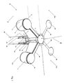
- Fig. 1:
- ein Grundsystem des Verbindungselements mit angedeuteten Möbelteilen und Ergänzungen,
- Fig. 2:
- eine Schnittdarstellung eines Grundsystems des Verbindungselements,
- Fig. 3:
- eine Schnittdarstellung eines konischen Formteils mit Steg und Arretierungsmittel,
- Fig. 4:
- eine Schnittdarstellung eines Grundsystems des Verbindungselements mit Buchse und Flansch im Bereich des konischen Formteils,
- Fig. 5:
- einen Schnitt des Bolzens zur Ausbildung des zylinderförmigen Formteils,
- Fig. 6:
- einen Schnitt des Spannmittels zur Ausbildung des zylinderförmigen Formteils,
- Fig. 7:
- einen Schnitt des Konusses zur Aufnahme des zylinderförmigen Formteils,
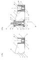
- Fig. 8:
- einen Schnitt durch ein Holzmöbelteil mit Konus zur Aufnahme des zylinderförmigen Formteils,
- Fig. 9:
- einen Schnitt durch ein metallisches Möbelteil mit Konus zur Aufnahme des zylinderförmigen Formteils,
- Fig. 10:
- eine schematische Draufsicht eines eingesetzten Grundelements mit angedeuteten verbundenen Möbelteilen,
- Fig. 11:
- eine Draufsicht auf ein konisches Formteil mit Steg und Arretierungsmittel sowie einem ergänzenden Flansch.
- Fig. 1:
- a basic system of the connecting element with indicated furniture parts and supplements,
- Fig. 2:
- a sectional view of a basic system of the connecting element,
- 3:
- a sectional view of a conical molding with web and locking means,
- 4:
- a sectional view of a basic system of the connecting element with socket and flange in the region of the conical molding,
- Fig. 5:
- a section of the bolt for forming the cylindrical molding,
- Fig. 6:
- a section of the clamping means for forming the cylindrical shaped part,
- Fig. 7:
- a section of the cone for receiving the cylindrical molding,
- Fig. 8:
- a section through a wooden furniture part with cone for receiving the cylindrical molding,
- Fig. 9:
- a section through a metallic furniture part with cone for receiving the cylindrical molding,
- Fig. 10:
- a schematic plan view of a basic element used with indicated connected furniture parts,
- Fig. 11:
- a plan view of a conical molding with web and locking means and a supplementary flange.
Die nachfolgende ausführliche Beschreibung des Verbindungselements 1 und das damit ausgeführte Verbindungssystem wird beispielsweise an Möbelteilen 30; 31 - 31x beschrieben, die zu einem Tisch oder Tischsystem verbunden werden sollen, wobei das Möbelteil 30 ein Tischbein ist, das bei dieser gewählten Ausführungsform mit einer längsgeschlitzten Bohrung 26 versehen ist, und die Möbelteile 31 - 31x die Tischplatten sind. Allerdings schließt das nachfolgend beschriebene Beispiel die Verbindung von anderen Möbelteilen und -baugruppen mit diesem Verbindungselement 1 und Verbindungssystem nicht aus.For example, the following detailed description of the
Das in Fig.1 mit durchgehenden Linien gezeigte Grundsystem eines Verbindungselements 1 besteht aus einem konischen Formteil 3 und dem Steg 4, der einstückig mit dem konischen Formteil 3 ist, und dem zylinderförmigen Formteil 2, an dem der Steg 4 unlösbar oder über Arretierungsmittel 14 lösbar festgelegt ist.The basic system of a connecting
Dieses Grundsystem des Verbindungselements 1 kann, wie beispielsweise durch gestrichelte Linien in Fig. 1 gezeigt, mit einem oder mehreren und mit dem konischen Formteil 3 identischen konischen Formteilen 3a; 3b; 3x, die ebenfalls mit identischen Stegen 4a; 4b; 4x einstückig ausgebildet sind, ergänzt werden.This basic system of the connecting
Dabei kann ein Verbindungselement 1 aus einem einstückigen Verbindungselement 1 bestehen, bei dem zwei konische Formteile 3 - 3b um 180° versetzt oder aus einem Verbindungselement 1, bei dem konische Formteile 3 - 3x um 90° und oder aus einem Verbindungselement 1, bei dem konische Formteile 3 - 3x zweimal um 90° und einmal um 180° versetzt oder aus einem Verbindungselement 1, bei dem zwei konische Formteile 3, 3a um 90° und ein konisches Formteil 3c um 135° zu den Formteilen 3, 3a versetzt am zylinderförmigen Formteil 2 festgelegt sind oder aus einem Verbindungselement 1 bestehen, bei dem einzelne konische Formteile 3 - 3x wahlweise nach der gewünschten Ausführungsform des Systemmöbels, beispielsweise eines Tisches oder eines Tischsystems am zylinderförmigen Teil 2 lösbar arretiert werden.In this case, a connecting
Ein Verbindungselement 1, bei dem an einem zentral liegenden zylinderförmigen Formteil 2 identische konische Formkörper 3 lösbar festgelegt sind, ist sehr variabel in den Verbindungsmöglichkeiten von Möbelteilen 30, 31 - 31x und wirtschaftlich in der Herstellung und Anwendung und wird daher als bevorzugtes Verbindungselement 1 der näheren Erläuterung zugrundegelegt, wobei die nachfolgenden Ausführungen zur Befestigung des zylinderförmigen Formteils 2 im Möbelteil 30 und die konische Ausführung der Mantelfläche sowie die Befestigung der konischen Formteile 3 - 3x auf ein einstückig ausgebildetes Verbindungselement übertragbar sind.A connecting
Das in Fig. 2 gezeigte Grundsystem eines lösbaren Verbindungselements 1 besteht aus einem konischen Formteil 3, und dem daran einstückig verbundenen Steg 4. Am freien Ende des Steges 4 ist ein Arretierungsmittel 14 ausgebildet, mit dem das konische Formteil 3 über den Steg 4 am zylinderförmigen Formteil 2 spielfrei und lagestabil festgelegt ist.The basic system of a detachable connecting
Das zylinderförmige Formteil 2 besteht aus einem Bolzen 8, der am unteren Ende mit einem hinterdrehten und durchmesservergrößerten Ansatz 10 und am oberen Ende mit einer Gewindebohrung 39 ausgebildet ist, in der ein Spannmittel 11 einschraubbar ist.The cylindrical shaped
Das Spannmittel 11 ist mit einem zum Ansatz 10 des Bolzens 8 gerichteten hinterdrehten Ansatz 12 versehen, der mit dem gegenüberliegenden hinterdrehten Ansatz 10 des Bolzens 8 die Befestigungspunkte für die Arretierungsmittel 14 des Stegs 4 ausbilden.The clamping means 11 is provided with a directed to the
Ausgehend vom Ende des hinterdrehten Ansatzes 10 ist im Bolzen 8 ein Innenkonus 18 ausgebildet, der mit einen korrospondierenden Konus 19 im Möbelteil 30, der beispielsweise über einem sich am Konus 19 anschließenden Befestigungsmittel 35 im Möbelteil 30 festgelegt ist, zusammenwirkt.Starting from the end of the back-turned
Der Konus 19 ist bevorzugt im Bereich des größten Durchmessers mit einer Ringnut 22 ausgebildet, in der ein Sicherungsring 21 eingelegt ist, der mit einer Ringnut 20 zusammenwirkt, die dekkungsgleich zur Ringnut 22 des Konusses 19 im Innenkonus 18 des Bolzens 8 gelegt ist.The
Der Bolzen 8 ist zusätzlich mit einer Durchgangsbohrung 23 versehen, die axial fluchtend zu einer Bohrung 41 liegt, die im Spannmittel 11 vorgesehen ist. Durch die Bohrung 41 des Spannmittels 11 und die Durchgangsbohrung 23 im Bolzen 8 ist bevorzugt eine Spannschraube 25 geführt, mit der das aus Bolzen 8 und Spannmittel 11 bestehende zylinderförmige Formteil 2 in einer im Konus 19 des Möbelteils 30 vorgesehenen Gewindebohrung 28 verspannt werden kann. In diesem Fall ist der obere Bereich der Bohrung 41 mit einem durchmesservergrößerten Ansatz 40 für die Aufnahme des Kopfes der Spannschraube 25 ausgebildet, der eine Tiefe aufweist, dass der Kopf der Spannschraube 25 mindestens flächig zur Oberfläche des Spannmittels 11 abschliesst oder um die Dicke einer aufzusetzenden Dekorabdeckung 42 versenkt ist.The
Fig. 3 zeigt ein konisches Formteil 3 mit Steg 4 und Arretierungsmittel 14, die bevorzugt aus einem einstückigen Gussteil bestehen. Das an der freien Stirnseite 13 des Steges 4 liegende Arretierungsmittel 14 besteht bevorzugt aus zwei gegenüberliegenden hakenförmigen Ansätzen 15, 16 und einer zur Mantelfläche der Buchse 8 korrospondierenden Anlagefläche 17. Das Arretierungsmittel 14 mit der Anlagefläche 17 und den hakenförmigen Ansätzen 15, 16 kann dabei direkt an der freien Stirnseite 13 des Steges 4 ausgebildet sein, vorteilhaft ist jedoch, wenn das Arretierungsmittel 14 an einem verbreiterten Ansatz des Steges 4 ausgebildet wird, der beispielsweise bei aneinandergefügten Arretierungsmitteln 14 - 14x gleich 360° ergibt. Auf diese Weise wird eine großflächigere Lastaufnahme des Arretierungsmittels 14 und damit eine verbesserte Kraftübertragung auf den Bolzen 8 des zylinderförmigen Formteils 2 erreicht, so dass die verbundenen Möbelteile 30, 31; 31a; 31b; 31x eine wesentlich erhöhte Stabilität aufweisen.Fig. 3 shows a conical shaped
Zur Ausbildung des konischen Verlaufs des Formteils 3 ist bei dieser speziellen Ausführungsform, wie u.a. in Fig. 3 gezeigt, die Mantelfläche 6 des Formteils 3 mit einer axial verlaufenden durchmesserverkleinerten Eindrehung 9 ausgebildet, in der eine Hülse 7 mit einer konisch verlaufenden Oberfläche 7a axial lagestabilisiert eingesetzt ist. Die Hülse 7 ist bevorzugt eine austauschbare Schlitzhülze und besteht vorteilhafterweise aus einem Hartkunststoff.To form the conical shape of the
Zur Ausbildung des konischen Verlaufs des Formteils 3 kann aber auch die Mantelfläche 6 des Formteils 3 mit nicht gezeigten und gleichmäßig auf dem Umfang des Formteils 3 versetzten Einfräsungen ausgebildet sein, in die konisch verlaufende Längsstreifen 5 lösbar oder unlösbar eingesetzt werden.For the formation of the conical shape of the molded
Das konische Formteil 3 kann aber auch aus einem einstückigen Kegelstumpf bestehen, der ohne oder mit gleichmäßig ausgefrästen konischen Längsstreifen versehen ist.But the conical shaped
Das konische Formteil 3 kann zusätzlich mit einem Innenkonus 36 und einer sich nach oben anschließenden Gewindebohrung 27 ausgebildet sein, um bei Bedarf das konische Formteil 3 mit dem zu verbindenden Möbelteil 31 - 31x zu verspannen.The conical shaped
Fig. 4 zeigt eine bevorzugte Ausführungsform der Verbindung zwischen dem Formteil 3 und den Möbelteilen 31 - 31x, mit der insbesondere eine geschlitzte Aufnahmeöffnung 29 in den Möbelteilen 31- 31x nach dem Einsetzen des konischen Formteils 3 formstabil bleibt. Zu diesem Zweck ist in der Aufnahmeöffnung 29 eine mindestens teilweise geschlitzte Buchse 32 deckungsgleich mit dem Schlitz der geschlitzten Aufnahmeöffnung 29 eingesetzt, die mit einem Ansatz 33 ausgebildet ist, der sich gegen die unten liegenden Fläche eines Möbelteils 31 - 31x abstützt und der lösbare Verbindungsmittel 37 aufweist, die mit der angrenzenden Fläche eines Möbelteils 31 - 31x verbindbar sind.Fig. 4 shows a preferred embodiment of the connection between the molded
Zusätzlich kann der Ansatz 33 an der unteren Seite mit einem vollständig oder teilweise umlaufenden oder einzeln versetzten Stabilisierungsmittel 38, wie beispielsweise einer Nut, ausgebildet sein, in die mindestens ein Stabilisierungsmittel 38a eingreift, das, wie in Fig. 11 gezeigt, an einem umlaufenden Flansch 34 ausgebildet ist, der mit dem konischen Formteil 3 einstückig ist. Damit werden die wirkenden Kräfte in der Aufnahmeöffnung 29 durch die Buchse 32 kompensiert und die Aufnahmeöffnung 29 bleibt nach dem Einsetzen des konischen Formteils 3 formstabil und den innewohnenden Eigenschaften von Holz oder holzähnlichen Materialien wird entgegengewirkt. Folglich sichert die Verbindung dauerhaft auch nach mehrmaligen Montagen und Demontagen immer einen stabilen Stand der miteinander verbundenen Möbelteile 30, 31; 31a; 31b; 31x.Additionally, the
Fig. 8 und Fig. 9 zeigen ein Möbelteil 30 aus Holz bzw. aus einem metallischen Material mit einer einfachen oder mehrfach längsgeschlitzten Bohrung 26 zur Durchführung der Steges 4; 4a; 4b; 4x, die einstückig mit dem konischen Formteil 3; 3a; 3b; 3x sind. Unterhalb der Schlitzung der Bohrung 26 ist in der schlitzlos weitergeführten Bohrung 26 und auf dem Grund der Bohrung 26 der Konus 19 zur Aufnahme des zylinderförmigen Formteils 2 mit dem Befestigungsmittel 35 so festgelegt, dass der Innenkonus 18 des zylinderförmigen Formteils 2 behinderungsfrei und vollständig mit dem Konus 19 verspannt werden kann. Die Bohrung 26 kann auch vorteilhafterweise nach der Schlitztiefe für den Steg 4 in ungeschlitzter Form weitergeführt werden und sich auch vollständig durch das Möbelteil 30 erstrecken. In diesem Fall ist eine Befestigungsbuchse 43 in der Bohrung 26 positioniert, die mit einem Verbindungsmittel zur Aufnahme des Befestigungsmittels 35 des Konusses 19 ausgebildet ist. Bei dieser Ausführungsart ist das Befstigungsmittel 43 über geeignete und nicht dargestellte Mittel axial lagestabil in der Bohrung 29 festgelegt und bevorzugt zusätzlich verklebt.Fig. 8 and Fig. 9 show a
Zur Ausführung eines Verbindungssystems mit einem lösbar verbundenen Verbindungselement 1 beispielsweise zum Zusammenfügen eines Tisches oder eines bestimmten Tischsystems wird das Verbindungselement 1 individuell nach der gewünschten Ausführung eines Tisches oder eines Tischsystems zusammengestellt. Dazu werden entsprechend der gewünschten Ausführungsform des Tisches oder Tischsystems am zylinderförmigen Formteil 2 ein oder mehrere konische Formteile 3 - 3x jeweils über den Steg 4 - 4x und den daran angeordneten Arretierungsmitteln 14 - 14x spielfrei arretiert. Zu diesem Zweck wird jeweils der hakenförmige Ansatz 16 eines Arretierungsmittels 14 - 14x in den hinterdrehten Ansatz 10 des Bolzens 6 eingesetzt und die Anlageflächen 17 eines jeden Arretierungsmittels 14 - 14x an die mit der Anlagefläche 17 korrospondierende Mantelfläche des Bolzens 8 angedrückt.To carry out a connection system with a releasably connected connecting
Anschließend wird das Spannmittel 11 mit dem zu den Arretierungsmitteln 14 - 14x gerichteten hinterdrehten Ansatz 12 in den Bolzen 8 eingeschaubt, wobei der hakenförmige Ansatz 15 der Arretierungsmittel 14 - 14x in den hinterdrehten Ansatz 12 des Spannmittels 11 eingreift, so dass die eingesetzten Stege 4 - 4x nach dem Verspannen des Spannmittels 11 lagestabil und spielfrei am Bolzen 8 und damit am zylinderförmigen Formteil 2 fixiert sind.Subsequently, the clamping means 11 with the locking means 14 - 14x directed rear-turned
Damit kann das Verbindungselement 1 auf eine sehr einfache Art und Weise mit identischen Bauteilen individuell ausgelegt werden und ist für die unterschiedlichsten Verbindungssysteme von Möbelteilen 30, 31; 31a; 31b; 31x, insbesondere von Tischen und Tischformationen, nutzbar.Thus, the connecting
Ein Verbindungssystem mit einem so zusammengefügten Verbindungselement 1, das aber auch ein einstückiges Verbindungselement 1 sein kann, ist in Fig. 10 gezeigt, das der einfachheitshalber nur ein liniares Verbindungselement 1 ist. Die Verbindungsform zwischen dem Möbelteil 31 und dem konischen Formteil 3 ist aber prinzipiell auch auf die Verbindungsformen zwischen den Möbelteilen 31a - 31x und den konischen Formteilen 3a - 3x übertragbar.A connection system with a connecting
Wie in Fig 4 gezeigt, ist das zylinderförmige Formteil 2 des Verbindungsmittels 1 in ein Möbelteil 30 eingesetzt, wie es beispielsweise in Fig. 8 und Fig. 9 gezeigt ist. Beim Einsetzen des zylinderförmigen Formteils 2 in die geschlitzte Bohrung 26 wird der Steg 4 bündig durch den Schlitz 4 durchgeführt und der Innenkonus 18 von dem Konus 19 im Möbelteil 30 aufgenommen und somit das zylinderförmige Formteil 2 lagestabilisiert. Anschließend wird das zylinderförmige Formteil 2 im Konus 19 mittels der Spannschraube 25 verspannt.As shown in FIG. 4, the cylindrical shaped
Nach dem arretierten Festlegen des zylinderförmigen Formteils 2 im Möbelteil 30, in diesem Fall einem Tischbein, wird auf das konische Formteil 2 ein Möbelteil 31, in diesem Fall eine Tischplatte mit einer in der geschlitzten Aufnahmeöffnung 29 zur Durchführung des Steges 4 aufgelegt. Bei der in Fig. 4 und Fig. 10 bevorzugt gezeigten Ausführungsform ist eine der geschlitzten Aufnahmeöffnung 29 angepaßte Buchse 32 mit einem Ansatz 33 eingesetzt und bevorzugt eingeklebt, die mit lösbaren Verbindungsmitteln 37 zum Möbelteil 31 und einem Stabilisierungsmittel 38 ausgebildet ist.After the locked setting of the cylindrical shaped
Ebenfalls, wie bei der in Fig. 4 oder Fig. 10 gezeigten speziellen Ausführungsform, ist in diesem Fall das konische Formteil 3 mit einem durchmesservergrößerten Flansch 34 ausgebildet, auf dem ein Stabilisierungsmittel 38a gelegt ist, wie auch in Fig. 11 gezeigt, das mit dem Stabilisierungsmittel 38 am Ansatz 33 der Buchse 32 nach dem Aufsetzen des Möbelteils 31, in diesem Fall wieder der Tischplatte, zusammenwirkt und damit die Buchse in der geschlitzten Aufnahmeöffnung 29 stabilisiert.Also, as in the specific embodiment shown in Fig. 4 or Fig. 10, in this case, the
Bei Bedarf kann dann das eingesetzte konische Formteil 3 in der Aufnahmeöffnung 29 mittels des ausgebildeten Innenkonusses 36 und der sich daran anschließenden Gewindebohrung 27 verspannt werden.If necessary, then the inserted
Zur veränderten designerischen Gestaltung der Oberfläche eines Tisches oder eines Tischsystems kann das Verbindungselement 1 auch insgesamt oder teilweise tiefer in die Möbelteile 30; 31 - 31x eingelegt und mit einer Dekorabdeckung 42 teilweise oder vollständig überdeckt werden.To the changed designerische design of the surface of a table or a table system, the connecting
- 11
- Verbindungselementconnecting element
- 22
- zylinderförmiges Formteilcylindrical shaped part
- 3 - 3x3 - 3x
- konisches Formteilconical molding
- 4 - 4x4 - 4x
- Stegweb
- 55
- konische Längsstreifenconical longitudinal stripes
- 66
- Mantelflächelateral surface
- 77
- Hülseshell
- 7a7a
- Oberflächesurface
- 88th
- Bolzenbolt
- 99
- durchmesserverkleinerte Eindrehungdiameter-reduced recess
- 1010
- hinterdrehter Ansatzbackside approach
- 1111
- Spannmittelclamping means
- 1212
- hinterdrehter Ansatzbackside approach
- 1313
- freie Stirnseitefree front page
- 14 - 14x14 - 14x
- Arretierungsmittellocking
- 1515
- hakenförmiger Ansatzhook-shaped approach
- 1616
- hakenförmiger Ansatzhook-shaped approach
- 1717
- Anlageflächecontact surface
- 1818
- Innenkonusinner cone
- 1919
- Konuscone
- 2020
- Ringnutring groove
- 2121
- Sicherungsringcirclip
- 2222
- Ringnutring groove
- 2323
- DurchgangsbohrungThrough Hole
- 2424
- Innengewindeinner thread
- 2525
- Spannschraubeclamping screw
- 2626
- längsgeschlitzte Bohrunglongitudinally slotted bore
- 2727
- Gewindebohrungthreaded hole
- 2828
- Gewindebohrungthreaded hole
- 2929
- Aufnahmeöffnungreceiving opening
- 3030
- Möbelteilfurniture part
- 31 - 31x31 - 31x
- Möbelteilfurniture part
- 3232
- BuchseRifle
- 3333
- Ansatz/BuchseApproach / socket
- 3434
- Flanschflange
- 3535
- Befestigungsmittelfastener
- 3636
- Innenkonusinner cone
- 3737
- lösbare Verbindungsmittelreleasable connection means
- 38 - 38a38 - 38a
- Stabilisierungsmittelstabilizer
- 3939
- Gewindebohrungthreaded hole
- 4040
- Ansatzapproach
- 4141
- Bohrungdrilling
- 4242
- Dekorabdeckungdecorative top
- 4343
- Befestigungsbuchsemounting bushing
Claims (18)
Applications Claiming Priority (1)
| Application Number | Priority Date | Filing Date | Title |
|---|---|---|---|
| DE200520017024 DE202005017024U1 (en) | 2005-10-31 | 2005-10-31 | Connecting element and detachable connection for system furniture |
Publications (2)
| Publication Number | Publication Date |
|---|---|
| EP1779747A2 true EP1779747A2 (en) | 2007-05-02 |
| EP1779747A3 EP1779747A3 (en) | 2011-04-13 |
Family
ID=36500642
Family Applications (1)
| Application Number | Title | Priority Date | Filing Date |
|---|---|---|---|
| EP06022567A Withdrawn EP1779747A3 (en) | 2005-10-31 | 2006-10-28 | Fastening element and detachable fastening system for prefabricated furniture or subassemblies |
Country Status (2)
| Country | Link |
|---|---|
| EP (1) | EP1779747A3 (en) |
| DE (1) | DE202005017024U1 (en) |
Cited By (1)
| Publication number | Priority date | Publication date | Assignee | Title |
|---|---|---|---|---|
| CN108999857A (en) * | 2018-07-27 | 2018-12-14 | 上海壹墨图文设计制作有限公司 | A kind of activity support connection structure |
Families Citing this family (2)
| Publication number | Priority date | Publication date | Assignee | Title |
|---|---|---|---|---|
| DE202008002538U1 (en) | 2008-02-22 | 2008-06-26 | Trümper, Jörg | Detachable connection |
| EP4187109A1 (en) * | 2021-11-30 | 2023-05-31 | Hilti Aktiengesellschaft | Bone shaped panel connector |
Citations (3)
| Publication number | Priority date | Publication date | Assignee | Title |
|---|---|---|---|---|
| FR2425010A1 (en) * | 1978-05-02 | 1979-11-30 | Foucault Henri De | Furniture component assembly connector - has two pins joined by strip to fit in mating recess |
| WO1990009505A2 (en) * | 1989-02-09 | 1990-08-23 | Cassese S.A. | Device for assembling frames and frame mouldings and machine for cutting mitre joints for implementation of said device |
| DE19522037A1 (en) * | 1995-06-17 | 1996-12-19 | Stoll Sedus Ag | Table column and support connector |
-
2005
- 2005-10-31 DE DE200520017024 patent/DE202005017024U1/en not_active Expired - Lifetime
-
2006
- 2006-10-28 EP EP06022567A patent/EP1779747A3/en not_active Withdrawn
Patent Citations (3)
| Publication number | Priority date | Publication date | Assignee | Title |
|---|---|---|---|---|
| FR2425010A1 (en) * | 1978-05-02 | 1979-11-30 | Foucault Henri De | Furniture component assembly connector - has two pins joined by strip to fit in mating recess |
| WO1990009505A2 (en) * | 1989-02-09 | 1990-08-23 | Cassese S.A. | Device for assembling frames and frame mouldings and machine for cutting mitre joints for implementation of said device |
| DE19522037A1 (en) * | 1995-06-17 | 1996-12-19 | Stoll Sedus Ag | Table column and support connector |
Cited By (2)
| Publication number | Priority date | Publication date | Assignee | Title |
|---|---|---|---|---|
| CN108999857A (en) * | 2018-07-27 | 2018-12-14 | 上海壹墨图文设计制作有限公司 | A kind of activity support connection structure |
| CN108999857B (en) * | 2018-07-27 | 2023-10-03 | 上海壹墨图文设计制作有限公司 | Movable support connecting structure |
Also Published As
| Publication number | Publication date |
|---|---|
| EP1779747A3 (en) | 2011-04-13 |
| DE202005017024U1 (en) | 2006-05-11 |
Similar Documents
| Publication | Publication Date | Title |
|---|---|---|
| DE102010037837B4 (en) | Table system | |
| EP1779747A2 (en) | Fastening element and detachable fastening system for prefabricated furniture or subassemblies | |
| EP0606880B1 (en) | Fastening means for a slab-like element on a wall or the same | |
| DE2515118A1 (en) | FITTING FOR ASSEMBLING DISASSEMBLY FURNITURE | |
| DE2625181A1 (en) | BASIC OR ADJUSTABLE PLATE FOR HINGES, IN PARTICULAR FOR FURNITURE HINGES | |
| DE3920959C2 (en) | ||
| DE202008007378U1 (en) | screw clip | |
| DE3507157C2 (en) | Stand furniture set | |
| EP2241211B1 (en) | Table system | |
| EP1134170B1 (en) | Modular structure for assembly of storage shelves | |
| DE10030919B4 (en) | Dismountable profile tube frame and table system with such a profile tube frame | |
| DE4442747C2 (en) | Modular shelving system | |
| AT396005B (en) | FASTENING ELEMENT WITH A DOWEL-LIKE SOCKET | |
| DE10051397B4 (en) | Dismantling piece of furniture | |
| EP1477624B1 (en) | Adjustable support | |
| DE202007008397U1 (en) | Furniture system and furniture | |
| DE2549352A1 (en) | Furniture hinge fitting element - has circular base with concentric mounting section having diameter equal to fitting part length to be supported | |
| DE102004022471A1 (en) | connecting element | |
| DE2128890C3 (en) | Console, especially for holding radiators | |
| DE19703416C2 (en) | Device for connecting furniture parts | |
| DE102022110430A1 (en) | Component and connecting element for a furniture system | |
| DE7807785U1 (en) | CASTLER WITH A BRACKET FOR ITS RELEASABLE ATTACHMENT | |
| DE102005058758A1 (en) | Room divider, with wall units or furniture supported at vertical pillars, has round tube pillars with structured grooves for the knotting points to be clamped as mountings | |
| DE202011051042U1 (en) | Connection arrangement and furniture system | |
| AT503129A4 (en) | CONNECTING FITTING FOR WOODEN PARTS |
Legal Events
| Date | Code | Title | Description |
|---|---|---|---|
| PUAI | Public reference made under article 153(3) epc to a published international application that has entered the european phase |
Free format text: ORIGINAL CODE: 0009012 |
|
| AK | Designated contracting states |
Kind code of ref document: A2 Designated state(s): AT BE BG CH CY CZ DE DK EE ES FI FR GB GR HU IE IS IT LI LT LU LV MC NL PL PT RO SE SI SK TR |
|
| AX | Request for extension of the european patent |
Extension state: AL BA HR MK YU |
|
| PUAL | Search report despatched |
Free format text: ORIGINAL CODE: 0009013 |
|
| AK | Designated contracting states |
Kind code of ref document: A3 Designated state(s): AT BE BG CH CY CZ DE DK EE ES FI FR GB GR HU IE IS IT LI LT LU LV MC NL PL PT RO SE SI SK TR |
|
| AX | Request for extension of the european patent |
Extension state: AL BA HR MK RS |
|
| 19U | Interruption of proceedings before grant |
Effective date: 20111026 |
|
| AKX | Designation fees paid |
Designated state(s): AT BE BG CH CY CZ DE DK EE ES FI FR GB GR HU IE IS IT LI LT LU LV MC NL PL PT RO SE SI SK TR |
|
| 19W | Proceedings resumed before grant after interruption of proceedings |
Effective date: 20120301 |
|
| STAA | Information on the status of an ep patent application or granted ep patent |
Free format text: STATUS: THE APPLICATION HAS BEEN WITHDRAWN |
|
| 18W | Application withdrawn |
Effective date: 20120301 |