EP1779719A1 - Pickup guard mounting arrangement - Google Patents
Pickup guard mounting arrangement Download PDFInfo
- Publication number
- EP1779719A1 EP1779719A1 EP06123036A EP06123036A EP1779719A1 EP 1779719 A1 EP1779719 A1 EP 1779719A1 EP 06123036 A EP06123036 A EP 06123036A EP 06123036 A EP06123036 A EP 06123036A EP 1779719 A1 EP1779719 A1 EP 1779719A1
- Authority
- EP
- European Patent Office
- Prior art keywords
- tine
- pickup
- guard
- bracket
- slot
- Prior art date
- Legal status (The legal status is an assumption and is not a legal conclusion. Google has not performed a legal analysis and makes no representation as to the accuracy of the status listed.)
- Granted
Links
- 238000003306 harvesting Methods 0.000 claims abstract description 5
- 239000000463 material Substances 0.000 claims description 6
- 239000004459 forage Substances 0.000 claims description 3
- 238000005452 bending Methods 0.000 description 4
- 238000003466 welding Methods 0.000 description 3
- 241001124569 Lycaenidae Species 0.000 description 2
- 230000008901 benefit Effects 0.000 description 2
- 238000004519 manufacturing process Methods 0.000 description 2
- 230000002411 adverse Effects 0.000 description 1
- 230000003466 anti-cipated effect Effects 0.000 description 1
- 230000000694 effects Effects 0.000 description 1
- 230000006872 improvement Effects 0.000 description 1
- 238000012423 maintenance Methods 0.000 description 1
- 230000007246 mechanism Effects 0.000 description 1
- 238000000034 method Methods 0.000 description 1
- 230000008569 process Effects 0.000 description 1
- 230000008439 repair process Effects 0.000 description 1
- 230000035939 shock Effects 0.000 description 1
- 238000005728 strengthening Methods 0.000 description 1
- 230000007704 transition Effects 0.000 description 1
- 239000002023 wood Substances 0.000 description 1
Images


Classifications
-
- A—HUMAN NECESSITIES
- A01—AGRICULTURE; FORESTRY; ANIMAL HUSBANDRY; HUNTING; TRAPPING; FISHING
- A01D—HARVESTING; MOWING
- A01D89/00—Pick-ups for loaders, chaff-cutters, balers, field-threshers, or the like, i.e. attachments for picking-up hay or the like field crops
- A01D89/001—Pick-up systems
- A01D89/002—Rotors
Definitions
- the present invention relates to an agricultural pickup and, more particularly, to a pickup tine guard with an improved mounting.
- Pickups used on agricultural harvesting machines such as, for example, balers and forage harvesters typically include a reel that is rotatable about a horizontal axis.
- the reel has a plurality of tines mounted on bars for movement in a generally circular path to lift crop material from the ground and feed it rearwardly into a crop processing mechanism.
- the tine bars are connected to a central shaft by end plates, and as the reel rotates, the tines project through spaces or gaps formed between tine guards arranged side-by-side transversely of the reel.
- These tine guards are individually secured by bolts at their top and bottom ends to support members on the pickup.
- U.S. Patent No. 3,397,527 granted on August 20, 1968 to O. W. Luek et al. discloses a conventional mounting arrangement for the tine guards wherein each guard is secured by four bolts or rivets at its top and bottom ends.
- U.S. Patent No. 5,052,171 granted on October 1, 1991 to Gary L. Bich et al. discloses a tine mounting arrangement that comprises upper and lower mounting plates that are removably attached to upper and lower frame members, respectively, on the pickup.
- the pickup includes a reel having a plurality of tines that project, as the reel rotates, through spaces or gaps formed between the tine guards.
- the upper ends of the tine guards are secured to the upper mounting plate while the lower ends of the tine guards are secured to the lower mounting plate so that the tine guards are removed together with the mounting plates when the mounting plates are detached from the pickup frame members.
- pickups of the nature described herein are placed under considerable stress during operation due to encounters with crop materials, stones, pieces of wood and the like. Such stresses are in generally exhibited as side and other bending forces that often damage the tine guards.
- Such a pickup attachment is easier to manufacture and less costly to assemble and disassemble.
- the improved pickup guard mounting assembly has a hook in the tine guide strip that is inserted into a slot to help hold it in position.
- the agricultural pickup is constructed in such a way to strengthen the pickup to better endure bending and beam forces created by encounters with foreign objects and to give sideways stability to the tine guide at the bottom.
- a pickup 10 for agricultural machines such as balers and forage harvesters includes a reel 12 supported at one end by a wheel 14, and the other end by conventional means (not shown).
- the reel 12 has a central shaft 16 with a generally horizontal axis 18, and a plurality of tines 20 arranged in spaced apart rows along the length of the central shaft 16.
- the tines 20 are mounted on transverse bars 22 that extend between end plates (not shown) fixed to the shaft 16 adjacent the ends thereof.
- Conventional drive means such as chains and sprockets (not shown) are provided to rotate the central shaft 16 and thereby cause movement of the tines 20 in a predetermined path P, known in the art, in order to lift crop material from the ground.
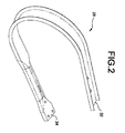
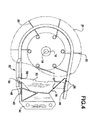
- Tine guards 28 are substantially C-shaped, as seen in Fig. 2, in side elevation and generally channel-shaped in cross section with their upper and lower end portions 32, 34, respectively, attached to bracket 36 (Fig. 4) by bolts 38, 40 (38 representing two bolts at the top and 40 representing three at the bottom, one each in holes 41, 42 and 43).
- Bracket 36 is affixed, as by welding, to the pickup frame 44, and extends angularly from an upper generally flat portion 46 to a generally flat lower portion 48, such that the upper end 32 is generally above the lower end 34.
- An elongate tine guide strip 50 abuts flat upper portion 46 on one end, and is affixed thereto as by welding or bolting, and extends through a slot 52 in angled bracket 36, terminating at the other end with a narrowed section that extends through slot 54 in the tee-pee portion of tine guard 28.
- the lower end of tine guide 50 also contains a slot or hook 56 formed therein on the forward side thereof to be pushed onto the forward edge of slot 54.
- the tine guide 50 With the back edge of the twine guide 50 generally matching or fitted to the general forward shape of bracket 36, and with a slight interference fit between the twine guide and the opening of the tine guard (i.e., the difference between the distance between the top edge of the twine guide and top of hook 56 and the distance between the top of slot 54 and the lower surface of upper flat portion 46) the tine guide 50 can be inserted and held in the position shown in Figs. 2 and 4 in a generally rigid manner.
- the structure described permits, in an alternative preferred embodiment, only one hole and one bolt would be used to attach guard 28 to pickup frame 44, thus providing significant savings in assembly and maintenance time.
- the structure is stiffened by the described tine guide to improve beam strength of the pickup and better endure bending forces due to adverse field operating conditions.
- a tee-pee section 60 of tine guard 28, best shown in Figs. 3 and 4, is narrower than the channel portion and contains the slot 54 on the top edge thereof.
- the term "tee-pee" is generally indicative of the transverse cross-sectional shape of that portion of the tine guard.
- the relative width of the tee-pee section allows for a larger opening between adjacent tine guards at the lower part of the pickup to provide a more ready exit for crop material, broken tines and other debris.
- the tee-pee section allows the mounting bolts to be at the back of the tine guard, allowing the guards to bend and absorb the shock when struck by an object.
- This particular pickup tine guard mounting arrangement has manufacturing cost advantages in that it reduces the number of bolts required to fasten the tine guard in place and the tine guide does not require welding at the bottom. Furthermore, and every bit as important, the instant invention provides a significantly improvement in pickup strength and stability.
- the stress is focused in the transition area between the tee-pee section and the flat lower end portion of the tine guard. This is a relatively weak part of the structure and will buckle if the force is sufficient (excessive forces are not necessary to cause buckling).
- the tine guard 28 and hook 56 on the tine guide 50 interlock to tie into the strength of the tee-pee, significantly strengthening the overall structure, reducing bending or buckling by foreign objects and giving improved sideways stability to the guide at the bottom.
Landscapes
- Life Sciences & Earth Sciences (AREA)
- Environmental Sciences (AREA)
- Outside Dividers And Delivering Mechanisms For Harvesters (AREA)
- Furnace Charging Or Discharging (AREA)
- Paper (AREA)
Abstract
Description
- The present invention relates to an agricultural pickup and, more particularly, to a pickup tine guard with an improved mounting.
- Pickups used on agricultural harvesting machines such as, for example, balers and forage harvesters typically include a reel that is rotatable about a horizontal axis. The reel has a plurality of tines mounted on bars for movement in a generally circular path to lift crop material from the ground and feed it rearwardly into a crop processing mechanism. The tine bars are connected to a central shaft by end plates, and as the reel rotates, the tines project through spaces or gaps formed between tine guards arranged side-by-side transversely of the reel. These tine guards are individually secured by bolts at their top and bottom ends to support members on the pickup.
U.S. Patent No. 3,397,527 granted on August 20, 1968 to O. W. Luek et al. discloses a conventional mounting arrangement for the tine guards wherein each guard is secured by four bolts or rivets at its top and bottom ends. -
U.S. Patent No. 5,052,171 granted on October 1, 1991 to Gary L. Bich et al. discloses a tine mounting arrangement that comprises upper and lower mounting plates that are removably attached to upper and lower frame members, respectively, on the pickup. The pickup includes a reel having a plurality of tines that project, as the reel rotates, through spaces or gaps formed between the tine guards. The upper ends of the tine guards are secured to the upper mounting plate while the lower ends of the tine guards are secured to the lower mounting plate so that the tine guards are removed together with the mounting plates when the mounting plates are detached from the pickup frame members. - At some point in time every pickup requires service, whether it is due to normal wear and tear or because of damage, and such service necessitates the removal of one or more tine guards in order to gain access to the reel. This type of service is quite time consuming, and thus costly, because, in most such situations quite a few tine guards must be removed to provide enough space to perform additional service work. Particularly in situations where the tine guards themselves are damaged or that damage extends across the front of the pickup, the amount of time and effort that must be expended to disassemble the components to provide adequate access to effect repair is such that the costs are excessive.
- Additionally, pickups of the nature described herein are placed under considerable stress during operation due to encounters with crop materials, stones, pieces of wood and the like. Such stresses are in generally exhibited as side and other bending forces that often damage the tine guards.
- It would be a great advantage to provide a tine guard mounting arrangement that overcomes the above problems and disadvantages.
- It is an object of the present invention to provide an improved tine guard mounting arrangement that avoids the above-noted disadvantages.
- According to the invention, there is provided a pickup attachment for an agricultural harvesting machine as claimed in claim 1.
- Such a pickup attachment is easier to manufacture and less costly to assemble and disassemble.
- Furthermore, the improved pickup guard mounting assembly has a hook in the tine guide strip that is inserted into a slot to help hold it in position.
- Additionally, the agricultural pickup is constructed in such a way to strengthen the pickup to better endure bending and beam forces created by encounters with foreign objects and to give sideways stability to the tine guide at the bottom.
- An embodiment of the present invention will now be described in further detail, by way of example, with reference to the following drawings, in which:
- Fig. 1 is a partial front elevation view of a pickup for agricultural machines, incorporating a tine guard mounting arrangement according to the preferred embodiment of the present invention;
- Fig. 2 is a sectional view, taken along lines 2-2 of Fig. 1;
- Fig. 3 is a partial perspective view of a tine guard, tine guide strip and tee-pee section of the assembly of the present invention, also showing the tine guard mounting holes; and
- Fig. 4 is a view, similar to Fig. 3, showing a tine guard, tine guide strip and tee-pee section.
- Many of the fastening, connection, processes and other means and components utilized in this invention are widely known and used in the field of the invention described, and their exact nature or type is not necessary for an understanding and use of the invention by a person skilled in the art, and they will not therefore be discussed in significant detail. Also, any reference herein to the terms "left" or "right" are used as a matter of mere convenience, and are determined by standing at the rear of the machine facing in its normal direction of travel. Furthermore, the various components shown or described herein for any specific application of this invention can be varied or altered as anticipated by this invention and the practice of a specific application of any element may already by widely known or used in the art by persons skilled in the art and each will likewise not therefore be discussed in significant detail.
- Referring to the figures, particularly Figs. 1 and 4, a pickup 10 for agricultural machines such as balers and forage harvesters includes a
reel 12 supported at one end by awheel 14, and the other end by conventional means (not shown). Thereel 12 has acentral shaft 16 with a generallyhorizontal axis 18, and a plurality oftines 20 arranged in spaced apart rows along the length of thecentral shaft 16. Thetines 20 are mounted ontransverse bars 22 that extend between end plates (not shown) fixed to theshaft 16 adjacent the ends thereof. Conventional drive means such as chains and sprockets (not shown) are provided to rotate thecentral shaft 16 and thereby cause movement of thetines 20 in a predetermined path P, known in the art, in order to lift crop material from the ground. - As the
tines 20 move along path P, they project through spaces orgaps 24 formed between anadjacent tine guards 28 that are arranged side-by-side transversely across thereel 12.Tine guards 28 are substantially C-shaped, as seen in Fig. 2, in side elevation and generally channel-shaped in cross section with their upper andlower end portions bolts 38, 40 (38 representing two bolts at the top and 40 representing three at the bottom, one each inholes Bracket 36 is affixed, as by welding, to thepickup frame 44, and extends angularly from an upper generallyflat portion 46 to a generally flatlower portion 48, such that theupper end 32 is generally above thelower end 34. An elongatetine guide strip 50 abuts flatupper portion 46 on one end, and is affixed thereto as by welding or bolting, and extends through a slot 52 inangled bracket 36, terminating at the other end with a narrowed section that extends throughslot 54 in the tee-pee portion oftine guard 28. The lower end oftine guide 50 also contains a slot orhook 56 formed therein on the forward side thereof to be pushed onto the forward edge ofslot 54. With the back edge of thetwine guide 50 generally matching or fitted to the general forward shape ofbracket 36, and with a slight interference fit between the twine guide and the opening of the tine guard (i.e., the difference between the distance between the top edge of the twine guide and top ofhook 56 and the distance between the top ofslot 54 and the lower surface of upper flat portion 46) thetine guide 50 can be inserted and held in the position shown in Figs. 2 and 4 in a generally rigid manner. The structure described permits, in an alternative preferred embodiment, only one hole and one bolt would be used to attachguard 28 topickup frame 44, thus providing significant savings in assembly and maintenance time. Moreover, the structure is stiffened by the described tine guide to improve beam strength of the pickup and better endure bending forces due to adverse field operating conditions. - A tee-
pee section 60 oftine guard 28, best shown in Figs. 3 and 4, is narrower than the channel portion and contains theslot 54 on the top edge thereof. The term "tee-pee" is generally indicative of the transverse cross-sectional shape of that portion of the tine guard. The relative width of the tee-pee section allows for a larger opening between adjacent tine guards at the lower part of the pickup to provide a more ready exit for crop material, broken tines and other debris. Moreover, the tee-pee section allows the mounting bolts to be at the back of the tine guard, allowing the guards to bend and absorb the shock when struck by an object. - This particular pickup tine guard mounting arrangement has manufacturing cost advantages in that it reduces the number of bolts required to fasten the tine guard in place and the tine guide does not require welding at the bottom. Furthermore, and every bit as important, the instant invention provides a significantly improvement in pickup strength and stability. When a prior art pickup hits an obstacle in the field the stress is focused in the transition area between the tee-pee section and the flat lower end portion of the tine guard. This is a relatively weak part of the structure and will buckle if the force is sufficient (excessive forces are not necessary to cause buckling). The tine guard 28 and hook 56 on the
tine guide 50 interlock to tie into the strength of the tee-pee, significantly strengthening the overall structure, reducing bending or buckling by foreign objects and giving improved sideways stability to the guide at the bottom. - It will be understood that changes in the details, materials, steps and arrangements of parts which have been described and illustrated to explain the nature of the invention will occur to and may be made by those skilled in the art upon a reading of this disclosure within the principles and scope of the invention.
Claims (9)
- A pickup attachment (10) for an agricultural harvesting machine comprising:a pickup frame mountable on the front of the agricultural harvesting machine, anda transverse reel assembly mounted on the pickup frame for picking up the crop material from the ground; the reel assembly comprises a series of tines (20) and a plurality of generally C-shaped spaced apart side-by-side tine guards (28), the ends of the tine guards (28) forming generally flat upper (32) and lower (34) end portions,characterised in that the reel assembly further comprises a tine guide (50) having a top end and an opposing bottom end, the top end having attachment means (38) thereon affixed to the flat upper end portion (32) of the tine guard (28) and the bottom end having a slot-like hook (56) therein, such that at least a portion of the bottom end of the tine guide (50) extends through a slot (54) in the lower end portion (34) of the tine guard (28), whereby each tine guide (50) is held in place between the upper (32) and lower (34) end portions of the respective tine guard (28) providing increased lateral and vertical stability and strength to the pickup attachment (10).
- A pickup attachment (10) as claimed in claim 1, wherein each tine guard (28) comprises a tee-pee section (60) forwardly of and adjacent the flat lower end portion (34), the slot (54) being on the upper surface of the tee-pee section (60) generally facing the flat upper end portion (32) of the guard (28) to allow the slot-like hook (56) to engage in the slot (54) in the tee-pee section (60).
- A pickup attachment (10) as claimed in claim 1 or 2, wherein the pickup frame comprises a bracket (36) having a generally flat first (46) and second (48) ends spaced apart a distance generally equivalent to the distance between the upper (32) and lower (34) end portions of the tine guards (28); and
the upper end portion (32) of each tine guard (28) is affixed to the flat first end (46) of the bracket (36) and the lower end portion (34) of each tine guard (28) is affixed to the flat second end (48) of the bracket (36). - A pickup attachment (10) as claimed in claim 3, wherein the bracket (36) includes a portion extending angularly across the vertical plane of the tine guide (50), the bracket (36) having an elongate supporting slot (52), through which the tine guide (50) is positioned.
- A pickup attachment (10) as claimed in claim 4, wherein the tine guide (50) has a forward edge and an opposing rearward edge and the rearward edge is generally shaped the same as the bracket (36) and is in general contact therewith.
- A pickup attachment (10) as claimed in claim 5, wherein the rearward edge of the tine guide (50), below the supporting slot (52) is generally in full contact with the bracket (36).
- A pickup attachment (10) as claimed in any of claims 3 to 6, wherein the bracket (36) has an irregularly shaped, in front to back vertical cross-section.
- A pickup attachment (10) as claimed in any of the preceding claims, wherein the pickup attachment (10) is mounted to an agricultural baler.
- A pickup attachment (10) as claimed in any of the claims 1 to 8, wherein the pickup attachment (10) is mounted to a forage harvester
Applications Claiming Priority (1)
| Application Number | Priority Date | Filing Date | Title |
|---|---|---|---|
| US11/262,440 US7478523B2 (en) | 2005-10-28 | 2005-10-28 | Pickup guard mounting arrangement |
Publications (2)
| Publication Number | Publication Date |
|---|---|
| EP1779719A1 true EP1779719A1 (en) | 2007-05-02 |
| EP1779719B1 EP1779719B1 (en) | 2009-01-14 |
Family
ID=37605751
Family Applications (1)
| Application Number | Title | Priority Date | Filing Date |
|---|---|---|---|
| EP06123036A Not-in-force EP1779719B1 (en) | 2005-10-28 | 2006-10-26 | Pickup guard mounting arrangement |
Country Status (4)
| Country | Link |
|---|---|
| US (1) | US7478523B2 (en) |
| EP (1) | EP1779719B1 (en) |
| AT (1) | ATE420551T1 (en) |
| DE (1) | DE602006004816D1 (en) |
Families Citing this family (12)
| Publication number | Priority date | Publication date | Assignee | Title |
|---|---|---|---|---|
| DE102006001338A1 (en) * | 2006-01-11 | 2007-07-26 | Deere & Company, Moline | crop receiver |
| US20100037577A1 (en) * | 2008-08-18 | 2010-02-18 | Egging Philip J | Crop Anti-Wrapping Method and Apparatus |
| US8863489B2 (en) | 2011-03-30 | 2014-10-21 | H & S Manufacturing Co., Inc. | Tine drive cam for windrow merger |
| US8181435B1 (en) | 2011-11-15 | 2012-05-22 | Cnh America Llc | Pick-up tine dividers |
| USD746876S1 (en) | 2012-10-18 | 2016-01-05 | Cnh Industrial America Llc | Crop stripper |
| US8959883B2 (en) | 2012-10-18 | 2015-02-24 | Cnh Industrial America Llc | Hook rotor stripper |
| US20140260168A1 (en) * | 2013-03-15 | 2014-09-18 | Rci Engineering Llc | Continuous windrow merger |
| US9426942B2 (en) * | 2014-06-20 | 2016-08-30 | Deere & Company | Hybrid crop stripper band for a crop pick-up |
| US10225985B2 (en) * | 2015-06-22 | 2019-03-12 | Vermeer Manufacturing Company | Pick-up device of a forage implement |
| US11980137B2 (en) * | 2020-06-09 | 2024-05-14 | Agco Corporation | Molded pickup stripper and attachment system for a baler |
| US11793114B2 (en) | 2021-03-23 | 2023-10-24 | Cnh Industrial America Llc | Agricultural vehicle including a pickup with a tine guide |
| US12593754B2 (en) | 2022-05-11 | 2026-04-07 | Vermeer Manufacturing Company | Round baler crop pickups |
Citations (5)
| Publication number | Priority date | Publication date | Assignee | Title |
|---|---|---|---|---|
| US3397527A (en) * | 1966-05-26 | 1968-08-20 | Sperry Rand Corp | Pickup guard mounting means |
| US3613345A (en) * | 1969-09-30 | 1971-10-19 | Deere & Co | Crop-handling means and stripper therefor |
| US3713283A (en) * | 1972-02-09 | 1973-01-30 | Int Harvester Co | Tine guiding device for crop pick-up |
| DE3518458A1 (en) * | 1985-05-22 | 1986-11-27 | Alois Pöttinger Landmaschinen-Gesellschaft mbH, 8900 Augsburg | Pick-up device for mown crops |
| US5052171A (en) * | 1990-08-29 | 1991-10-01 | Ford New Holland, Inc. | Pickup tine guard mounting arrangement |
Family Cites Families (14)
| Publication number | Priority date | Publication date | Assignee | Title |
|---|---|---|---|---|
| US1877519A (en) * | 1930-06-17 | 1932-09-13 | Case Co J I | Harvester |
| US2527887A (en) | 1947-04-18 | 1950-10-31 | Fmc Corp | Pickup mechanism for harvesting machines |
| US2682743A (en) * | 1952-03-17 | 1954-07-06 | Int Harvester Co | Harvester pickup |
| US2893537A (en) * | 1957-01-08 | 1959-07-07 | Ford Motor Co | Crop pickup mechanism |
| US3226921A (en) * | 1964-02-27 | 1966-01-04 | Sperry Rand Corp | Quick detachable means for a pick-up reel stripper bar |
| US3398527A (en) * | 1966-05-31 | 1968-08-27 | Air Force Usa | Corrugated wall radiation cooled combustion chamber |
| US4161859A (en) * | 1977-06-09 | 1979-07-24 | International Harvester Company | Crop pickup device |
| US4411127A (en) | 1982-04-05 | 1983-10-25 | Sperry Corporation | Floating windguard |
| US4524576A (en) * | 1984-03-02 | 1985-06-25 | Probst Evan N | Windrowed hay fluffing agricultural implement |
| US5426928A (en) | 1993-11-09 | 1995-06-27 | Deere & Company | Round baler pickup having radially fixed teeth cooperating with stripper plates to direct crop upwardly into bale chamber |
| US5394682A (en) * | 1993-11-09 | 1995-03-07 | Deere & Company | Round baler pickup having stiff teeth |
| GB9903624D0 (en) | 1999-02-18 | 1999-04-07 | Ford New Holland Nv | Movable windguard |
| US6314709B1 (en) | 1999-09-02 | 2001-11-13 | New Holland North America, Inc. | Tine guard for windrow pickup apparatus |
| US6314708B1 (en) | 2000-06-15 | 2001-11-13 | Deere & Company | Rotary conveyor tine stripper |
-
2005
- 2005-10-28 US US11/262,440 patent/US7478523B2/en active Active
-
2006
- 2006-10-26 EP EP06123036A patent/EP1779719B1/en not_active Not-in-force
- 2006-10-26 DE DE602006004816T patent/DE602006004816D1/en active Active
- 2006-10-26 AT AT06123036T patent/ATE420551T1/en not_active IP Right Cessation
Patent Citations (5)
| Publication number | Priority date | Publication date | Assignee | Title |
|---|---|---|---|---|
| US3397527A (en) * | 1966-05-26 | 1968-08-20 | Sperry Rand Corp | Pickup guard mounting means |
| US3613345A (en) * | 1969-09-30 | 1971-10-19 | Deere & Co | Crop-handling means and stripper therefor |
| US3713283A (en) * | 1972-02-09 | 1973-01-30 | Int Harvester Co | Tine guiding device for crop pick-up |
| DE3518458A1 (en) * | 1985-05-22 | 1986-11-27 | Alois Pöttinger Landmaschinen-Gesellschaft mbH, 8900 Augsburg | Pick-up device for mown crops |
| US5052171A (en) * | 1990-08-29 | 1991-10-01 | Ford New Holland, Inc. | Pickup tine guard mounting arrangement |
Also Published As
| Publication number | Publication date |
|---|---|
| ATE420551T1 (en) | 2009-01-15 |
| EP1779719B1 (en) | 2009-01-14 |
| US7478523B2 (en) | 2009-01-20 |
| US20070107402A1 (en) | 2007-05-17 |
| DE602006004816D1 (en) | 2009-03-05 |
Similar Documents
| Publication | Publication Date | Title |
|---|---|---|
| EP1779719B1 (en) | Pickup guard mounting arrangement | |
| US6351931B1 (en) | Crop header with draper canvas | |
| EP2165592B1 (en) | Row unit for an agricultural harvester | |
| US8205424B1 (en) | Baler pre-cutter rotor design having reinforced tines | |
| US8181435B1 (en) | Pick-up tine dividers | |
| US6598381B2 (en) | Multiple-part attachment for an agricultural machine | |
| US4519192A (en) | Hold-down sickle guard | |
| US5052171A (en) | Pickup tine guard mounting arrangement | |
| EP3108741B1 (en) | Pick-up device of a forage implement | |
| EP2957165B1 (en) | Crop stripper band | |
| US11425859B2 (en) | Header cutting system with knife guards | |
| US3670482A (en) | Two row row crop attachment with lower crop gathering means at the center than at the sides | |
| US20030110752A1 (en) | Guard for crop pick up apparatus | |
| US8312700B2 (en) | Tine assembly | |
| EP3610717A1 (en) | Slat-bar cross-members in a feederhouse crop-conveying system | |
| CA2311019C (en) | Crop header with draper canvas | |
| US3660970A (en) | Row crop attachment having frame with a transverse bar at the sickle | |
| US3596454A (en) | Divider board for windrower | |
| CA3000269A1 (en) | Device for harvesting stalk-like stem crops | |
| EP2989882B1 (en) | Feederhouse arrangement for mounting a header to a combine | |
| US3722195A (en) | Cutter bar for mower | |
| US5310008A (en) | Picker grate for a rock picker | |
| EP4393294A1 (en) | A grass pickup header | |
| US2882671A (en) | Stabilizer for sickle guards | |
| JPS6216821Y2 (en) |
Legal Events
| Date | Code | Title | Description |
|---|---|---|---|
| PUAI | Public reference made under article 153(3) epc to a published international application that has entered the european phase |
Free format text: ORIGINAL CODE: 0009012 |
|
| AK | Designated contracting states |
Kind code of ref document: A1 Designated state(s): AT BE BG CH CY CZ DE DK EE ES FI FR GB GR HU IE IS IT LI LT LU LV MC NL PL PT RO SE SI SK TR |
|
| AX | Request for extension of the european patent |
Extension state: AL BA HR MK YU |
|
| 17P | Request for examination filed |
Effective date: 20071102 |
|
| AKX | Designation fees paid |
Designated state(s): AT BE BG CH CY CZ DE DK EE ES FI FR GB GR HU IE IS IT LI LT LU LV MC NL PL PT RO SE SI SK TR |
|
| GRAP | Despatch of communication of intention to grant a patent |
Free format text: ORIGINAL CODE: EPIDOSNIGR1 |
|
| GRAS | Grant fee paid |
Free format text: ORIGINAL CODE: EPIDOSNIGR3 |
|
| GRAA | (expected) grant |
Free format text: ORIGINAL CODE: 0009210 |
|
| AK | Designated contracting states |
Kind code of ref document: B1 Designated state(s): AT BE BG CH CY CZ DE DK EE ES FI FR GB GR HU IE IS IT LI LT LU LV MC NL PL PT RO SE SI SK TR |
|
| REG | Reference to a national code |
Ref country code: GB Ref legal event code: FG4D |
|
| REG | Reference to a national code |
Ref country code: CH Ref legal event code: EP |
|
| REG | Reference to a national code |
Ref country code: IE Ref legal event code: FG4D |
|
| REF | Corresponds to: |
Ref document number: 602006004816 Country of ref document: DE Date of ref document: 20090305 Kind code of ref document: P |
|
| PG25 | Lapsed in a contracting state [announced via postgrant information from national office to epo] |
Ref country code: NL Free format text: LAPSE BECAUSE OF FAILURE TO SUBMIT A TRANSLATION OF THE DESCRIPTION OR TO PAY THE FEE WITHIN THE PRESCRIBED TIME-LIMIT Effective date: 20090114 |
|
| NLV1 | Nl: lapsed or annulled due to failure to fulfill the requirements of art. 29p and 29m of the patents act | ||
| PG25 | Lapsed in a contracting state [announced via postgrant information from national office to epo] |
Ref country code: SI Free format text: LAPSE BECAUSE OF FAILURE TO SUBMIT A TRANSLATION OF THE DESCRIPTION OR TO PAY THE FEE WITHIN THE PRESCRIBED TIME-LIMIT Effective date: 20090114 Ref country code: FI Free format text: LAPSE BECAUSE OF FAILURE TO SUBMIT A TRANSLATION OF THE DESCRIPTION OR TO PAY THE FEE WITHIN THE PRESCRIBED TIME-LIMIT Effective date: 20090114 Ref country code: LT Free format text: LAPSE BECAUSE OF FAILURE TO SUBMIT A TRANSLATION OF THE DESCRIPTION OR TO PAY THE FEE WITHIN THE PRESCRIBED TIME-LIMIT Effective date: 20090114 Ref country code: ES Free format text: LAPSE BECAUSE OF FAILURE TO SUBMIT A TRANSLATION OF THE DESCRIPTION OR TO PAY THE FEE WITHIN THE PRESCRIBED TIME-LIMIT Effective date: 20090425 |
|
| PG25 | Lapsed in a contracting state [announced via postgrant information from national office to epo] |
Ref country code: PT Free format text: LAPSE BECAUSE OF FAILURE TO SUBMIT A TRANSLATION OF THE DESCRIPTION OR TO PAY THE FEE WITHIN THE PRESCRIBED TIME-LIMIT Effective date: 20090615 Ref country code: PL Free format text: LAPSE BECAUSE OF FAILURE TO SUBMIT A TRANSLATION OF THE DESCRIPTION OR TO PAY THE FEE WITHIN THE PRESCRIBED TIME-LIMIT Effective date: 20090114 Ref country code: AT Free format text: LAPSE BECAUSE OF FAILURE TO SUBMIT A TRANSLATION OF THE DESCRIPTION OR TO PAY THE FEE WITHIN THE PRESCRIBED TIME-LIMIT Effective date: 20090114 Ref country code: SE Free format text: LAPSE BECAUSE OF FAILURE TO SUBMIT A TRANSLATION OF THE DESCRIPTION OR TO PAY THE FEE WITHIN THE PRESCRIBED TIME-LIMIT Effective date: 20090414 Ref country code: IS Free format text: LAPSE BECAUSE OF FAILURE TO SUBMIT A TRANSLATION OF THE DESCRIPTION OR TO PAY THE FEE WITHIN THE PRESCRIBED TIME-LIMIT Effective date: 20090514 Ref country code: LV Free format text: LAPSE BECAUSE OF FAILURE TO SUBMIT A TRANSLATION OF THE DESCRIPTION OR TO PAY THE FEE WITHIN THE PRESCRIBED TIME-LIMIT Effective date: 20090114 |
|
| PG25 | Lapsed in a contracting state [announced via postgrant information from national office to epo] |
Ref country code: BE Free format text: LAPSE BECAUSE OF FAILURE TO SUBMIT A TRANSLATION OF THE DESCRIPTION OR TO PAY THE FEE WITHIN THE PRESCRIBED TIME-LIMIT Effective date: 20090114 |
|
| PG25 | Lapsed in a contracting state [announced via postgrant information from national office to epo] |
Ref country code: DK Free format text: LAPSE BECAUSE OF FAILURE TO SUBMIT A TRANSLATION OF THE DESCRIPTION OR TO PAY THE FEE WITHIN THE PRESCRIBED TIME-LIMIT Effective date: 20090114 Ref country code: CZ Free format text: LAPSE BECAUSE OF FAILURE TO SUBMIT A TRANSLATION OF THE DESCRIPTION OR TO PAY THE FEE WITHIN THE PRESCRIBED TIME-LIMIT Effective date: 20090114 Ref country code: EE Free format text: LAPSE BECAUSE OF FAILURE TO SUBMIT A TRANSLATION OF THE DESCRIPTION OR TO PAY THE FEE WITHIN THE PRESCRIBED TIME-LIMIT Effective date: 20090114 |
|
| PLBE | No opposition filed within time limit |
Free format text: ORIGINAL CODE: 0009261 |
|
| STAA | Information on the status of an ep patent application or granted ep patent |
Free format text: STATUS: NO OPPOSITION FILED WITHIN TIME LIMIT |
|
| PG25 | Lapsed in a contracting state [announced via postgrant information from national office to epo] |
Ref country code: SK Free format text: LAPSE BECAUSE OF FAILURE TO SUBMIT A TRANSLATION OF THE DESCRIPTION OR TO PAY THE FEE WITHIN THE PRESCRIBED TIME-LIMIT Effective date: 20090114 Ref country code: RO Free format text: LAPSE BECAUSE OF FAILURE TO SUBMIT A TRANSLATION OF THE DESCRIPTION OR TO PAY THE FEE WITHIN THE PRESCRIBED TIME-LIMIT Effective date: 20090114 |
|
| 26N | No opposition filed |
Effective date: 20091015 |
|
| PG25 | Lapsed in a contracting state [announced via postgrant information from national office to epo] |
Ref country code: BG Free format text: LAPSE BECAUSE OF FAILURE TO SUBMIT A TRANSLATION OF THE DESCRIPTION OR TO PAY THE FEE WITHIN THE PRESCRIBED TIME-LIMIT Effective date: 20090414 |
|
| PG25 | Lapsed in a contracting state [announced via postgrant information from national office to epo] |
Ref country code: MC Free format text: LAPSE BECAUSE OF NON-PAYMENT OF DUE FEES Effective date: 20091031 |
|
| PG25 | Lapsed in a contracting state [announced via postgrant information from national office to epo] |
Ref country code: GR Free format text: LAPSE BECAUSE OF FAILURE TO SUBMIT A TRANSLATION OF THE DESCRIPTION OR TO PAY THE FEE WITHIN THE PRESCRIBED TIME-LIMIT Effective date: 20090415 Ref country code: IE Free format text: LAPSE BECAUSE OF NON-PAYMENT OF DUE FEES Effective date: 20091026 |
|
| PG25 | Lapsed in a contracting state [announced via postgrant information from national office to epo] |
Ref country code: LU Free format text: LAPSE BECAUSE OF NON-PAYMENT OF DUE FEES Effective date: 20091026 |
|
| REG | Reference to a national code |
Ref country code: CH Ref legal event code: PL |
|
| PG25 | Lapsed in a contracting state [announced via postgrant information from national office to epo] |
Ref country code: HU Free format text: LAPSE BECAUSE OF FAILURE TO SUBMIT A TRANSLATION OF THE DESCRIPTION OR TO PAY THE FEE WITHIN THE PRESCRIBED TIME-LIMIT Effective date: 20090715 |
|
| PG25 | Lapsed in a contracting state [announced via postgrant information from national office to epo] |
Ref country code: LI Free format text: LAPSE BECAUSE OF NON-PAYMENT OF DUE FEES Effective date: 20101031 Ref country code: CH Free format text: LAPSE BECAUSE OF NON-PAYMENT OF DUE FEES Effective date: 20101031 |
|
| PG25 | Lapsed in a contracting state [announced via postgrant information from national office to epo] |
Ref country code: TR Free format text: LAPSE BECAUSE OF FAILURE TO SUBMIT A TRANSLATION OF THE DESCRIPTION OR TO PAY THE FEE WITHIN THE PRESCRIBED TIME-LIMIT Effective date: 20090114 |
|
| PG25 | Lapsed in a contracting state [announced via postgrant information from national office to epo] |
Ref country code: CY Free format text: LAPSE BECAUSE OF FAILURE TO SUBMIT A TRANSLATION OF THE DESCRIPTION OR TO PAY THE FEE WITHIN THE PRESCRIBED TIME-LIMIT Effective date: 20090114 |
|
| REG | Reference to a national code |
Ref country code: DE Ref legal event code: R082 Ref document number: 602006004816 Country of ref document: DE Representative=s name: PATENTANWAELTE WALLACH, KOCH & PARTNER, DE |
|
| REG | Reference to a national code |
Ref country code: DE Ref legal event code: R081 Ref document number: 602006004816 Country of ref document: DE Owner name: CNH INDUSTRIAL BELGIUM NV, BE Free format text: FORMER OWNER: CNH BELGIUM NV, ZEDELGEM, BE Effective date: 20140428 Ref country code: DE Ref legal event code: R082 Ref document number: 602006004816 Country of ref document: DE Representative=s name: PATENTANWAELTE WALLACH, KOCH & PARTNER, DE Effective date: 20140428 Ref country code: DE Ref legal event code: R082 Ref document number: 602006004816 Country of ref document: DE Representative=s name: PATENTANWAELTE WALLACH, KOCH, DR. HAIBACH, FEL, DE Effective date: 20140428 |
|
| REG | Reference to a national code |
Ref country code: FR Ref legal event code: CD Owner name: CNH INDUSTRIAL BELGIUM NV Effective date: 20140725 |
|
| REG | Reference to a national code |
Ref country code: FR Ref legal event code: PLFP Year of fee payment: 10 |
|
| PGFP | Annual fee paid to national office [announced via postgrant information from national office to epo] |
Ref country code: GB Payment date: 20151008 Year of fee payment: 10 Ref country code: DE Payment date: 20151009 Year of fee payment: 10 Ref country code: IT Payment date: 20151005 Year of fee payment: 10 |
|
| PGFP | Annual fee paid to national office [announced via postgrant information from national office to epo] |
Ref country code: FR Payment date: 20151006 Year of fee payment: 10 |
|
| REG | Reference to a national code |
Ref country code: DE Ref legal event code: R119 Ref document number: 602006004816 Country of ref document: DE |
|
| GBPC | Gb: european patent ceased through non-payment of renewal fee |
Effective date: 20161026 |
|
| REG | Reference to a national code |
Ref country code: FR Ref legal event code: ST Effective date: 20170630 |
|
| PG25 | Lapsed in a contracting state [announced via postgrant information from national office to epo] |
Ref country code: FR Free format text: LAPSE BECAUSE OF NON-PAYMENT OF DUE FEES Effective date: 20161102 Ref country code: DE Free format text: LAPSE BECAUSE OF NON-PAYMENT OF DUE FEES Effective date: 20170503 Ref country code: GB Free format text: LAPSE BECAUSE OF NON-PAYMENT OF DUE FEES Effective date: 20161026 |
|
| PG25 | Lapsed in a contracting state [announced via postgrant information from national office to epo] |
Ref country code: IT Free format text: LAPSE BECAUSE OF NON-PAYMENT OF DUE FEES Effective date: 20161026 |