EP1779459B1 - Process for laminating components of an electrochemical cell - Google Patents
Process for laminating components of an electrochemical cell Download PDFInfo
- Publication number
- EP1779459B1 EP1779459B1 EP05768108A EP05768108A EP1779459B1 EP 1779459 B1 EP1779459 B1 EP 1779459B1 EP 05768108 A EP05768108 A EP 05768108A EP 05768108 A EP05768108 A EP 05768108A EP 1779459 B1 EP1779459 B1 EP 1779459B1
- Authority
- EP
- European Patent Office
- Prior art keywords
- electrically conductive
- conductive support
- support film
- electrode sheet
- electrode
- Prior art date
- Legal status (The legal status is an assumption and is not a legal conclusion. Google has not performed a legal analysis and makes no representation as to the accuracy of the status listed.)
- Expired - Lifetime
Links
Images


Classifications
-
- H—ELECTRICITY
- H01—ELECTRIC ELEMENTS
- H01M—PROCESSES OR MEANS, e.g. BATTERIES, FOR THE DIRECT CONVERSION OF CHEMICAL ENERGY INTO ELECTRICAL ENERGY
- H01M4/00—Electrodes
- H01M4/02—Electrodes composed of, or comprising, active material
- H01M4/64—Carriers or collectors
- H01M4/66—Selection of materials
- H01M4/661—Metal or alloys, e.g. alloy coatings
-
- B—PERFORMING OPERATIONS; TRANSPORTING
- B32—LAYERED PRODUCTS
- B32B—LAYERED PRODUCTS, i.e. PRODUCTS BUILT-UP OF STRATA OF FLAT OR NON-FLAT, e.g. CELLULAR OR HONEYCOMB, FORM
- B32B37/00—Methods or apparatus for laminating, e.g. by curing or by ultrasonic bonding
- B32B37/14—Methods or apparatus for laminating, e.g. by curing or by ultrasonic bonding characterised by the properties of the layers
- B32B37/16—Methods or apparatus for laminating, e.g. by curing or by ultrasonic bonding characterised by the properties of the layers with all layers existing as coherent layers before laminating
- B32B37/20—Methods or apparatus for laminating, e.g. by curing or by ultrasonic bonding characterised by the properties of the layers with all layers existing as coherent layers before laminating involving the assembly of continuous webs only
-
- H—ELECTRICITY
- H01—ELECTRIC ELEMENTS
- H01M—PROCESSES OR MEANS, e.g. BATTERIES, FOR THE DIRECT CONVERSION OF CHEMICAL ENERGY INTO ELECTRICAL ENERGY
- H01M4/00—Electrodes
- H01M4/02—Electrodes composed of, or comprising, active material
- H01M4/04—Processes of manufacture in general
- H01M4/0402—Methods of deposition of the material
- H01M4/0404—Methods of deposition of the material by coating on electrode collectors
-
- H—ELECTRICITY
- H01—ELECTRIC ELEMENTS
- H01M—PROCESSES OR MEANS, e.g. BATTERIES, FOR THE DIRECT CONVERSION OF CHEMICAL ENERGY INTO ELECTRICAL ENERGY
- H01M4/00—Electrodes
- H01M4/02—Electrodes composed of, or comprising, active material
- H01M4/04—Processes of manufacture in general
- H01M4/0402—Methods of deposition of the material
- H01M4/0409—Methods of deposition of the material by a doctor blade method, slip-casting or roller coating
-
- B—PERFORMING OPERATIONS; TRANSPORTING
- B32—LAYERED PRODUCTS
- B32B—LAYERED PRODUCTS, i.e. PRODUCTS BUILT-UP OF STRATA OF FLAT OR NON-FLAT, e.g. CELLULAR OR HONEYCOMB, FORM
- B32B2309/00—Parameters for the laminating or treatment process; Apparatus details
- B32B2309/02—Temperature
-
- B—PERFORMING OPERATIONS; TRANSPORTING
- B32—LAYERED PRODUCTS
- B32B—LAYERED PRODUCTS, i.e. PRODUCTS BUILT-UP OF STRATA OF FLAT OR NON-FLAT, e.g. CELLULAR OR HONEYCOMB, FORM
- B32B2309/00—Parameters for the laminating or treatment process; Apparatus details
- B32B2309/06—Angles
-
- B—PERFORMING OPERATIONS; TRANSPORTING
- B32—LAYERED PRODUCTS
- B32B—LAYERED PRODUCTS, i.e. PRODUCTS BUILT-UP OF STRATA OF FLAT OR NON-FLAT, e.g. CELLULAR OR HONEYCOMB, FORM
- B32B2309/00—Parameters for the laminating or treatment process; Apparatus details
- B32B2309/08—Dimensions, e.g. volume
- B32B2309/10—Dimensions, e.g. volume linear, e.g. length, distance, width
- B32B2309/105—Thickness
-
- B—PERFORMING OPERATIONS; TRANSPORTING
- B32—LAYERED PRODUCTS
- B32B—LAYERED PRODUCTS, i.e. PRODUCTS BUILT-UP OF STRATA OF FLAT OR NON-FLAT, e.g. CELLULAR OR HONEYCOMB, FORM
- B32B2309/00—Parameters for the laminating or treatment process; Apparatus details
- B32B2309/12—Pressure
-
- B—PERFORMING OPERATIONS; TRANSPORTING
- B32—LAYERED PRODUCTS
- B32B—LAYERED PRODUCTS, i.e. PRODUCTS BUILT-UP OF STRATA OF FLAT OR NON-FLAT, e.g. CELLULAR OR HONEYCOMB, FORM
- B32B2311/00—Metals, their alloys or their compounds
-
- B—PERFORMING OPERATIONS; TRANSPORTING
- B32—LAYERED PRODUCTS
- B32B—LAYERED PRODUCTS, i.e. PRODUCTS BUILT-UP OF STRATA OF FLAT OR NON-FLAT, e.g. CELLULAR OR HONEYCOMB, FORM
- B32B2457/00—Electrical equipment
- B32B2457/10—Batteries
-
- B—PERFORMING OPERATIONS; TRANSPORTING
- B32—LAYERED PRODUCTS
- B32B—LAYERED PRODUCTS, i.e. PRODUCTS BUILT-UP OF STRATA OF FLAT OR NON-FLAT, e.g. CELLULAR OR HONEYCOMB, FORM
- B32B37/00—Methods or apparatus for laminating, e.g. by curing or by ultrasonic bonding
- B32B37/06—Methods or apparatus for laminating, e.g. by curing or by ultrasonic bonding characterised by the heating method
-
- B—PERFORMING OPERATIONS; TRANSPORTING
- B32—LAYERED PRODUCTS
- B32B—LAYERED PRODUCTS, i.e. PRODUCTS BUILT-UP OF STRATA OF FLAT OR NON-FLAT, e.g. CELLULAR OR HONEYCOMB, FORM
- B32B37/00—Methods or apparatus for laminating, e.g. by curing or by ultrasonic bonding
- B32B37/14—Methods or apparatus for laminating, e.g. by curing or by ultrasonic bonding characterised by the properties of the layers
- B32B37/15—Methods or apparatus for laminating, e.g. by curing or by ultrasonic bonding characterised by the properties of the layers with at least one layer being manufactured and immediately laminated before reaching its stable state, e.g. in which a layer is extruded and laminated while in semi-molten state
- B32B37/153—Methods or apparatus for laminating, e.g. by curing or by ultrasonic bonding characterised by the properties of the layers with at least one layer being manufactured and immediately laminated before reaching its stable state, e.g. in which a layer is extruded and laminated while in semi-molten state at least one layer is extruded and immediately laminated while in semi-molten state
-
- H—ELECTRICITY
- H01—ELECTRIC ELEMENTS
- H01M—PROCESSES OR MEANS, e.g. BATTERIES, FOR THE DIRECT CONVERSION OF CHEMICAL ENERGY INTO ELECTRICAL ENERGY
- H01M6/00—Primary cells; Manufacture thereof
- H01M6/40—Printed batteries, e.g. thin film batteries
-
- Y—GENERAL TAGGING OF NEW TECHNOLOGICAL DEVELOPMENTS; GENERAL TAGGING OF CROSS-SECTIONAL TECHNOLOGIES SPANNING OVER SEVERAL SECTIONS OF THE IPC; TECHNICAL SUBJECTS COVERED BY FORMER USPC CROSS-REFERENCE ART COLLECTIONS [XRACs] AND DIGESTS
- Y02—TECHNOLOGIES OR APPLICATIONS FOR MITIGATION OR ADAPTATION AGAINST CLIMATE CHANGE
- Y02E—REDUCTION OF GREENHOUSE GAS [GHG] EMISSIONS, RELATED TO ENERGY GENERATION, TRANSMISSION OR DISTRIBUTION
- Y02E60/00—Enabling technologies; Technologies with a potential or indirect contribution to GHG emissions mitigation
- Y02E60/10—Energy storage using batteries
-
- Y—GENERAL TAGGING OF NEW TECHNOLOGICAL DEVELOPMENTS; GENERAL TAGGING OF CROSS-SECTIONAL TECHNOLOGIES SPANNING OVER SEVERAL SECTIONS OF THE IPC; TECHNICAL SUBJECTS COVERED BY FORMER USPC CROSS-REFERENCE ART COLLECTIONS [XRACs] AND DIGESTS
- Y02—TECHNOLOGIES OR APPLICATIONS FOR MITIGATION OR ADAPTATION AGAINST CLIMATE CHANGE
- Y02P—CLIMATE CHANGE MITIGATION TECHNOLOGIES IN THE PRODUCTION OR PROCESSING OF GOODS
- Y02P70/00—Climate change mitigation technologies in the production process for final industrial or consumer products
- Y02P70/50—Manufacturing or production processes characterised by the final manufactured product
-
- Y—GENERAL TAGGING OF NEW TECHNOLOGICAL DEVELOPMENTS; GENERAL TAGGING OF CROSS-SECTIONAL TECHNOLOGIES SPANNING OVER SEVERAL SECTIONS OF THE IPC; TECHNICAL SUBJECTS COVERED BY FORMER USPC CROSS-REFERENCE ART COLLECTIONS [XRACs] AND DIGESTS
- Y10—TECHNICAL SUBJECTS COVERED BY FORMER USPC
- Y10T—TECHNICAL SUBJECTS COVERED BY FORMER US CLASSIFICATION
- Y10T156/00—Adhesive bonding and miscellaneous chemical manufacture
- Y10T156/17—Surface bonding means and/or assemblymeans with work feeding or handling means
- Y10T156/1702—For plural parts or plural areas of single part
- Y10T156/1712—Indefinite or running length work
- Y10T156/1741—Progressive continuous bonding press [e.g., roll couples]
Definitions
- the present invention relates to a process for laminating a pair of electrode sheets onto an electrically conductive support film for lithium polymer batteries.
- Rechargeable batteries manufactured from laminates of solid polymer electrolytes and sheet-like anodes and cathodes displays many advantages over conventional liquid electrolytes batteries. These advantages include lower overall battery weight, high power density, high specific energy, longer service life, and environmental friendliness since the danger of spilling toxic liquid into the environment is eliminated.
- Lithium polymer battery components include positive electrodes, negative electrodes and an electrolyte separator capable of permitting ionic conductivity, such as an electrolyte consisting of a polymer and a lithium salt, sandwiched between the positive and negative electrodes.
- the negative electrodes, or anodes are usually made of light-weight metals such as alkali metals and alloys, typically lithium metal, lithium oxide, lithium-aluminum alloys and the like, or of carboneous material such as coke or graphite intercalated with lithium ion to form Li x C.
- the composite positive electrodes, or cathodes are usually formed of a mixture of insertion material, electronic conductive filler, usually carbon or graphite or mixture thereof, and an ionically conductive polymer electrolyte material, the mixture being set on a current collector, for example, a thin sheet of aluminum.
- Composite cathode thin films are usually obtained by solvent coating onto a current collector or by melt extrusion deposited onto the current collector film.
- the polymer electrolyte separator layer is typically produced by solvent coating or by melt extrusion.
- Solid lithium polymer electrochemical cells are typically manufactured by separately preparing the positive electrode, the electrolyte separator and the negative electrode and thereafter laminating each component together to form an electrochemical cell.
- U.S. Patent no. 5,536,278 to Armand et al . discloses one method of assembling the various components of a solid lithium polymer electrochemical cell.
- the positive electrode thin film is coated or layered onto a current collector.
- the polymer electrolyte is coated onto a plastic substrate such as a film of polypropylene.
- the positive electrode is thereafter laminated onto one face of the electrolyte, and the plastic substrate is then removed from the other face of the electrolyte and the lithium - negative electrode is applied thereon.
- U.S. Patent no. 5,100,746 to Gauthier discloses a method of laminating simultaneously a plurality of layers of components of an electrochemical cell that is adapted to speed up the manufacturing process, wherein double-layer solid polymer electrolyte/composite positive electrode sub-assemblies are subsequently associated with the other constituent layers of the electrochemical cell.
- Co-pending U.S. Patent Application Publication no. 2003/0215710 A1 discloses an efficient method of manufacturing a positive electrode film through a single or twin screw extruder and either depositing the positive electrode film directly onto a moving current collector film, or handling the positive electrode film through one or more rollers and thereafter laminating it onto a moving current collector film.
- the positive electrode material exiting the extruder die passes through chilled rollers prior to lamination onto the current collector film.
- the lamination of the positive electrode film onto the current collector must be fast and the positive electrode film must adhere properly onto a substrate such as a current collector.
- European Patent Application EP 0 730 952 A2 and Japanese Patent Application JP 60125646 A respectively disclose lamination processes of resin onto a metal strip in which heated rollers are used to raise the temperature of the metal strip.
- the invention provides a process for laminating a pair of electrode sheets onto an electrically conductive support film for lithium polymer batteries, said process comprising routing an electrically conductive support film having a first side and a second side through a nip formed by a pair of lamination rollers, laminating a first electrode sheet onto the first side of the electrically conductive support film before entering the nip formed by the pair of lamination rollers, laminating a second electrode sheet onto the second side of the electrically conductive support film through the nip formed by the pair of lamination rollers, and heating the first side of the electrically conductive support film and the first electrode sheet with a heating device adapted to direct heat towards a meeting point of the first electrode sheet and the first side of the electrically conductive support film such that the first electrode sheet and the first side of the electrically conductive support film are heated simultaneously prior to laminating the first electrode sheet onto the first side of the electrically conductive support film, and heating the second side of the electrically
- the first side of the electrically conductive support film is first brought into contact with the first electrode sheet and, thereafter, the second side of the electrically conductive support film is brought into contact with the second electrode sheet.
- the electrically conductive support film is passed through a series of stabilizing rollers prior to lamination.
- An apparatus suitable for laminating at least one electrode sheet onto an electrically conductive support film comprises lamination rollers forming a nip and means for carrying the electrically conductive support film and the at least one electrode sheet to the nip formed by the lamination rollers.
- the apparatus also comprises a heater for heating the electrically conductive support film before the electrically conductive support film reaches the nip formed by the lamination rollers.
- the means for carrying the electrically conductive support film and the at least one electrode sheet to the nip formed by the lamination rollers comprises means for carrying a first electrode sheet and a second electrode sheet to the nip.
- the means for carrying the first electrode sheet and the second electrode sheet to the nip is adapted to laminate the first electrode sheet onto a first side of the electrically conductive support film and to laminate the second electrode sheet onto a second side of the electrically conductive support film.
- the heater is a first heater and is aimed at a contact point between the electrically conductive support film and the first electrode sheet, and the apparatus further comprises a second heater aimed at a contact point between the electrically conductive support film and the second electrode sheet.
- the apparatus further comprises means for applying and controlling a pressure exerted by the lamination rollers at the nip onto the electrically conductive support film and the at least one electrode sheet.
- the production of thin sheets of composite electrode material is most efficiently done by melt extrusion through a slit die.
- the various constituents of the composite electrode material are fed from one or more hoppers into an extruder where they are melted, mixed and transported through an air-tight cylinder via a mixing screw.
- the molten material is extruded toward the slit die and discharged through an elongated discharge port of the slit die adjusted to a desired thickness of film or sheet at a constant rate.
- the production of thin sheets of composite electrode material may also be done by a solvent coating method.
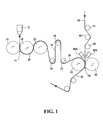
- Figure 1 illustrates a first example of a lamination apparatus in which a composite cathode material is extruded through a slot die 12 and into a nip 14 formed by a pair of rollers 16 and 18 maintained at a certain temperature.
- the temperature at which the rollers 16 and 18 are maintained can be of 12°C or less.
- the extruded composite cathode material is thereby formed into a sheet or film 20 of a certain thickness.
- the thickness of the composite cathode sheet 20 may be in the range of about 30 ⁇ m to about 100 ⁇ m.
- the composite cathode sheet 20 remains in contact with the roller 18 for approximately 180° of rotation, during which time it is allowed to cool and acquire a solid state.
- the composite cathode sheet 20 is then transferred onto the surface of the roller 22, which is also maintained at a certain temperature, and remains in contact with the surface of the roller 22 for a portion of its rotation.
- the composite cathode sheet 20 then follows the path defined by rollers 24, 26 and 28 which leads to lamination rollers 30 and 32.
- the composite cathode sheet 20 is self-supporting. That is, it is sufficiently consistent to be self-supporting and does not require a support film, such as, for example, a plastic film, in order to be transported from the slot die 12 to the lamination rollers 30 and 32.
- the composite cathode sheet 20 In contact with the surface of the lamination roller 30, the composite cathode sheet 20 follows the rotation of the lamination roller 30 and enters into a nip 34 formed between the lamination rollers 30 and 32. In the nip 34, the composite cathode sheet 20 meets and is bonded to an electrically conductive support film 40 under the pressure exerted by the lamination rollers 30 and 32 to form a single side or monoface cathode/current collector laminate 42.
- the position of the lamination rollers 30 and 32 is adjustable such that the pressure applied onto the cathode/current collector laminate 42 being formed is also adjustable.
- the pressure is maintained between about 69 kPa (10 psi) and about 207 kPa (30 psi). In a particular example of implementation, the pressure is maintained at about 138 kPa (20 psi).
- the cathode/current collector laminate 42 is then either rolled up for storage or transported to another processing station.
- the electrically conductive support film 40 is heated by a pair of heaters 45A and 45B prior to entering the nip 34 and bonding with the composite cathode sheet 20.
- Each one of the heaters 45A and 45B may be any type of heating device adapted to direct heat towards a target area, such as, for example, an infrared light or an electrical resistance element with or without air flow ventilation.
- the surface temperature of the electrically conductive support film 40 is raised by heaters 45A and 45B in order to increase the quality of adhesion between the composite cathode sheet 20 and the electrically conductive support film 40.
- the surface of the composite cathode sheet 20 softens to create an intimate interface with the surface of the electrically conductive support film 40, thereby forming an intimate bond between the two sheets 20 and 40.
- the electrically conductive support film 40 is heated to a temperature of approximately 40°C.
- the temperature at which the electrically conductive support film 40 is heated may vary widely depending on the type of material and thickness of the electrically conductive support film 40.
- the heaters 45A and 45B are aimed directly at the nip 34 formed by the lamination rollers 30 and 32, thereby heating simultaneously the electrically conductive support film 40 and the composite cathode sheet 20.
- the temperature of the electrically conductive support film 40 is raised and the composite cathode sheet 20 is softened in order to increase the quality of adhesion between the composite cathode sheet 20 and the electrically conductive support film 40.
- the electrically conductive support film 40 refers to any type of current collector known to those skilled in the art of electrochemical cells.
- suitable current collectors can be selected from the group consisting of metallic foils in general, and more specifically metallic foils of aluminum, copper, nickel and alloys of those metals, conductive plastics, metal coated polymer sheets, metallic foils or grids coated with adhesion promoters, anti-corrosion protective layers, metal oxides, and various other types of conductive member devised over decades of research and development.
- the electrically conductive support film 40 passes through a series of rollers 47, 48 and 49 prior to lamination.
- the combination of the rollers 47, 48 and 49 stabilizes the electrically conductive support film 40 such that it does not waver or seesaw when entering the nip 34 and contacting the composite cathode sheet 20.
- Figure 2 illustrates a second example of a lamination apparatus in which additional stabilizing rollers 51, 52, 53, 54, 55 and 56 define a more intricate path adapted to prevent lateral wavering and zigzagging of the electrically conductive support film 40.
- the last stabilizing roller 56 is in an offset position relative to the nip 58 formed by the lamination rollers 60 and 62.
- the offset position of the stabilizing roller 56 directs the electrically conductive support film 40 such that the electrically conductive support film 40 meets the composite electrode sheet 50 before entering the nip 58.
- the tension of the electrically conductive support film 40 exerts the initial force or pressure which bonds together the electrically conductive support film 40 and the composite electrode sheet 50.
- the heaters 45A and 45B are positioned to accommodate the angular entry of the electrically conductive support film 40 into the nip 58 defined by the lamination rollers 60 and 62.
- the heater 45A is aimed at the meeting point of the electrically conductive support film 40 and the composite electrode sheet 50 such that they are heated simultaneously to promote adhesion at the initial contact point of the composite electrode sheet 50 and the electrically conductive support film 40.
- the monoface laminate 64 comprising the composite electrode sheet 50 and the electrically conductive support film 40, enters the nip 58 where it is put under pressure applied by the lamination rollers 60 and 62 to securely bond together the two layers of the laminate 64.
- the laminate 64 is then carried away for storage or transported to another processing station.
- Figure 3 illustrates a lamination apparatus suitable for use for the process according to the invention.
- a first electrode sheet 70 exiting a slot die is routed through a series of rollers 71, 72 and 73 and led to a lamination roller 74.
- a second electrode sheet 80 exiting another slot die is routed through a series of rollers 76, 77 and 78 and led to a lamination roller 75.
- An electrically conductive support film 40 is routed through a series of stabilizing rollers 82, 84, 86, 88, 90 and 92 which prevent wavering and zigzagging of the electrically conductive support film 40, thereby ensuring that the electrically conductive support film 40 is stable when it is bonded to the first electrode sheet 70.
- the last stabilizing roller 92 is in an offset position relative to a nip 95 formed by the lamination rollers 74 and 75 such that the electrically conductive support film 40 meets and is bonded to the first electrode sheet 70 at an acute angle before entering the nip 95.
- the tension of the electrically conductive support film 40 exerts the initial force or pressure which bonds the electrically conductive support film 40 to the first electrode sheet 70.
- Heaters 45A and 45B are positioned to accommodate the angular entry of the electrically conductive support film 40 into the nip 95 formed by the lamination rollers 74 and 75.
- the heaters 45A and 45B are respectively aimed at the meeting points of the electrically conductive support film 40 and the first and second electrode sheets 70 and 80 such that they are heated simultaneously to promote adhesion at the initial contact points of the electrode sheets 70 and 80 and the electrically conductive support film 40.
- the surface temperature of the electrically conductive support film 40 is raised by the heaters 45A and 45B and the first and second electrode sheets 70 and 80 are softened in order to increase the quality of adhesion and create an intimate interface between the electrode sheets 70 and 80 and the electrically conductive support film 40.
- one side of the electrically conductive support film 40 is first laminated onto the first electrode sheet 70.
- the second electrode sheet 80 is then laminated onto the other side of the electrically conductive support film 40 when entering the nip 95.
- the lamination rollers 74 and 75 apply pressure onto a laminate 96, comprising the first and second electrode sheets 70 and 80 and the electrically conductive support film 40, in order to increase the adhesion between the components of the laminate 96 and to prevent any air bubbles from forming between the electrode sheets 70 and 80 and the electrically conductive support film 40.
- the bi-face laminate 96 which comprises the electrode sheets 70 and 80 each securely bonded to a respective side of the electrically conductive support film 40, is carried away for storage or transported to another processing station.
- the heaters 45A and 45B heat the electrically conductive support film 40 to a temperature of approximately 40°C. However, this temperature may vary widely depending on the type of material and thickness of the electrically conductive support film 40.
- the pressure applied by the lamination rollers 74 and 75 may vary widely depending on the type of electrode material being laminated.
- the pressure exerted by the lamination rollers 74 and 75 is maintained between about 69 kPa (10 psi) and about 207 kPa (30 psi).
- the pressure exerted by the lamination rollers 74 and 75 is maintained at about 138 kPa (20 psi).
- the application and control of the pressure exerted by the lamination rollers 74 and 75 at the nip 95 is achieved by either an hydraulic or pneumatic system (not shown) or by a mechanical system (not shown) with or without sensors.
- the electrode sheets 20, 50, 70 and 80 are self-supporting and do not require a support film, such as, for example, a plastic film, in order to be transported to the lamination rollers.
- a support film such as a plastic support film, may be used for transporting each of the electrode sheets.
Landscapes
- Chemical & Material Sciences (AREA)
- Engineering & Computer Science (AREA)
- Chemical Kinetics & Catalysis (AREA)
- Electrochemistry (AREA)
- General Chemical & Material Sciences (AREA)
- Manufacturing & Machinery (AREA)
- Materials Engineering (AREA)
- Battery Electrode And Active Subsutance (AREA)
- Lining Or Joining Of Plastics Or The Like (AREA)
- Secondary Cells (AREA)
- Primary Cells (AREA)
Abstract
Description
- The present invention relates to a process for laminating a pair of electrode sheets onto an electrically conductive support film for lithium polymer batteries.
- Rechargeable batteries manufactured from laminates of solid polymer electrolytes and sheet-like anodes and cathodes displays many advantages over conventional liquid electrolytes batteries. These advantages include lower overall battery weight, high power density, high specific energy, longer service life, and environmental friendliness since the danger of spilling toxic liquid into the environment is eliminated.
- Lithium polymer battery components include positive electrodes, negative electrodes and an electrolyte separator capable of permitting ionic conductivity, such as an electrolyte consisting of a polymer and a lithium salt, sandwiched between the positive and negative electrodes. The negative electrodes, or anodes, are usually made of light-weight metals such as alkali metals and alloys, typically lithium metal, lithium oxide, lithium-aluminum alloys and the like, or of carboneous material such as coke or graphite intercalated with lithium ion to form LixC. The composite positive electrodes, or cathodes, are usually formed of a mixture of insertion material, electronic conductive filler, usually carbon or graphite or mixture thereof, and an ionically conductive polymer electrolyte material, the mixture being set on a current collector, for example, a thin sheet of aluminum.
- Composite cathode thin films are usually obtained by solvent coating onto a current collector or by melt extrusion deposited onto the current collector film. Similarly, the polymer electrolyte separator layer is typically produced by solvent coating or by melt extrusion.
- Solid lithium polymer electrochemical cells are typically manufactured by separately preparing the positive electrode, the electrolyte separator and the negative electrode and thereafter laminating each component together to form an electrochemical cell.
U.S. Patent no. 5,536,278 to Armand et al . discloses one method of assembling the various components of a solid lithium polymer electrochemical cell. The positive electrode thin film is coated or layered onto a current collector. The polymer electrolyte is coated onto a plastic substrate such as a film of polypropylene. The positive electrode is thereafter laminated onto one face of the electrolyte, and the plastic substrate is then removed from the other face of the electrolyte and the lithium - negative electrode is applied thereon. Although this manufacturing process is reasonably efficient for research and development and small-scale production of lithium polymer electrochemical cells, it is inadequate for large-scale production of such cells. -
U.S. Patent no. 5,100,746 to Gauthier discloses a method of laminating simultaneously a plurality of layers of components of an electrochemical cell that is adapted to speed up the manufacturing process, wherein double-layer solid polymer electrolyte/composite positive electrode sub-assemblies are subsequently associated with the other constituent layers of the electrochemical cell. - Co-pending
U.S. Patent Application Publication no. 2003/0215710 A1 discloses an efficient method of manufacturing a positive electrode film through a single or twin screw extruder and either depositing the positive electrode film directly onto a moving current collector film, or handling the positive electrode film through one or more rollers and thereafter laminating it onto a moving current collector film. The positive electrode material exiting the extruder die passes through chilled rollers prior to lamination onto the current collector film. To achieve cost-effective production levels and to produce a high quality electrochemical cell, the lamination of the positive electrode film onto the current collector must be fast and the positive electrode film must adhere properly onto a substrate such as a current collector. - European Patent Application
EP 0 730 952 A2 and Japanese Patent ApplicationJP 60125646 A - In order to improve the efficiency of the production process for large-scale manufacturing of lithium polymer batteries, there is a need for an improved process for laminating a pair of electrode sheets onto an electrically conductive support film, wherein the process increases the quality of adhesion between the electrode sheets and the support film.
- It is an object of the present invention to provide a process for laminating a pair of electrode sheets onto an electrically conductive support film for lithium polymer batteries.
- In accordance with a first broad aspect, the invention provides a process for laminating a pair of electrode sheets onto an electrically conductive support film for lithium polymer batteries, said process comprising routing an electrically conductive support film having a first side and a second side through a nip formed by a pair of lamination rollers, laminating a first electrode sheet onto the first side of the electrically conductive support film before entering the nip formed by the pair of lamination rollers, laminating a second electrode sheet onto the second side of the electrically conductive support film through the nip formed by the pair of lamination rollers, and heating the first side of the electrically conductive support film and the first electrode sheet with a heating device adapted to direct heat towards a meeting point of the first electrode sheet and the first side of the electrically conductive support film such that the first electrode sheet and the first side of the electrically conductive support film are heated simultaneously prior to laminating the first electrode sheet onto the first side of the electrically conductive support film, and heating the second side of the electrically conductive support film and the second electrode sheet with a second heating device adapted to direct heat towards a meeting point of the second electrode sheet and the second side of the electrically conductive support film such that the second electrode sheet and the second side of the electrically conductive support film are heated simultaneously prior to entering the nip formed by the pair of lamination rollers.
- Furthermore, in a specific embodiment, the first side of the electrically conductive support film is first brought into contact with the first electrode sheet and, thereafter, the second side of the electrically conductive support film is brought into contact with the second electrode sheet.
- In a specific embodiment, the electrically conductive support film is passed through a series of stabilizing rollers prior to lamination.
- An apparatus suitable for laminating at least one electrode sheet onto an electrically conductive support film comprises lamination rollers forming a nip and means for carrying the electrically conductive support film and the at least one electrode sheet to the nip formed by the lamination rollers. The apparatus also comprises a heater for heating the electrically conductive support film before the electrically conductive support film reaches the nip formed by the lamination rollers.
- In an apparatus suitable for use for the process according to the invention, the means for carrying the electrically conductive support film and the at least one electrode sheet to the nip formed by the lamination rollers comprises means for carrying a first electrode sheet and a second electrode sheet to the nip. The means for carrying the first electrode sheet and the second electrode sheet to the nip is adapted to laminate the first electrode sheet onto a first side of the electrically conductive support film and to laminate the second electrode sheet onto a second side of the electrically conductive support film. The heater is a first heater and is aimed at a contact point between the electrically conductive support film and the first electrode sheet, and the apparatus further comprises a second heater aimed at a contact point between the electrically conductive support film and the second electrode sheet.
- In a particular example of implementation, the apparatus further comprises means for applying and controlling a pressure exerted by the lamination rollers at the nip onto the electrically conductive support film and the at least one electrode sheet.
- These and other aspects and features of the present invention will now become apparent to those of ordinary skill in the art upon review of the following description of specific examples of implementation of the invention in conjunction with the accompanying drawings.
- A detailed description of specific examples of implementation of the present invention is provided herein below, by way of example only, with reference to the accompanying drawings, in which:
-
Figure 1 is a schematic frontal view of a lamination apparatus; -
Figure 2 is a schematic frontal view of another lamination apparatus and -
Figure 3 is a schematic frontal view of a lamination apparatus suitable for use for the process according to the invention. - In general, the production of thin sheets of composite electrode material is most efficiently done by melt extrusion through a slit die. The various constituents of the composite electrode material are fed from one or more hoppers into an extruder where they are melted, mixed and transported through an air-tight cylinder via a mixing screw. The molten material is extruded toward the slit die and discharged through an elongated discharge port of the slit die adjusted to a desired thickness of film or sheet at a constant rate. The production of thin sheets of composite electrode material may also be done by a solvent coating method.
-
Figure 1 illustrates a first example of a lamination apparatus in which a composite cathode material is extruded through aslot die 12 and into anip 14 formed by a pair ofrollers rollers film 20 of a certain thickness. For example, the thickness of thecomposite cathode sheet 20 may be in the range of about 30 µm to about 100 µm. Thecomposite cathode sheet 20 remains in contact with theroller 18 for approximately 180° of rotation, during which time it is allowed to cool and acquire a solid state. - The
composite cathode sheet 20 is then transferred onto the surface of theroller 22, which is also maintained at a certain temperature, and remains in contact with the surface of theroller 22 for a portion of its rotation. Thecomposite cathode sheet 20 then follows the path defined byrollers lamination rollers composite cathode sheet 20 is self-supporting. That is, it is sufficiently consistent to be self-supporting and does not require a support film, such as, for example, a plastic film, in order to be transported from the slot die 12 to thelamination rollers - In contact with the surface of the
lamination roller 30, thecomposite cathode sheet 20 follows the rotation of thelamination roller 30 and enters into anip 34 formed between thelamination rollers nip 34, thecomposite cathode sheet 20 meets and is bonded to an electricallyconductive support film 40 under the pressure exerted by thelamination rollers current collector laminate 42. The position of thelamination rollers current collector laminate 42 being formed is also adjustable. Advantageously, the pressure is maintained between about 69 kPa (10 psi) and about 207 kPa (30 psi). In a particular example of implementation, the pressure is maintained at about 138 kPa (20 psi). The cathode/current collector laminate 42 is then either rolled up for storage or transported to another processing station. - In the example shown in
Figure 1 , the electricallyconductive support film 40 is heated by a pair ofheaters nip 34 and bonding with thecomposite cathode sheet 20. Each one of theheaters conductive support film 40 is raised byheaters composite cathode sheet 20 and the electricallyconductive support film 40. When thecomposite cathode sheet 20 contacts the heated surface of the electricallyconductive support film 40, the surface of thecomposite cathode sheet 20 softens to create an intimate interface with the surface of the electricallyconductive support film 40, thereby forming an intimate bond between the twosheets conductive support film 40 is heated to a temperature of approximately 40°C. However, it is to be understood that the temperature at which the electricallyconductive support film 40 is heated may vary widely depending on the type of material and thickness of the electricallyconductive support film 40. - Advantageously, in the example shown in
Figure 1 , theheaters nip 34 formed by thelamination rollers conductive support film 40 and thecomposite cathode sheet 20. In so doing, the temperature of the electricallyconductive support film 40 is raised and thecomposite cathode sheet 20 is softened in order to increase the quality of adhesion between thecomposite cathode sheet 20 and the electricallyconductive support film 40. - The electrically
conductive support film 40 refers to any type of current collector known to those skilled in the art of electrochemical cells. For example, suitable current collectors can be selected from the group consisting of metallic foils in general, and more specifically metallic foils of aluminum, copper, nickel and alloys of those metals, conductive plastics, metal coated polymer sheets, metallic foils or grids coated with adhesion promoters, anti-corrosion protective layers, metal oxides, and various other types of conductive member devised over decades of research and development. - In the example shown in
Figure 1 , the electricallyconductive support film 40 passes through a series ofrollers rollers conductive support film 40 such that it does not waver or seesaw when entering thenip 34 and contacting thecomposite cathode sheet 20. -
Figure 2 illustrates a second example of a lamination apparatus in which additional stabilizingrollers conductive support film 40. Furthermore, the last stabilizingroller 56 is in an offset position relative to the nip 58 formed by thelamination rollers roller 56 directs the electricallyconductive support film 40 such that the electricallyconductive support film 40 meets thecomposite electrode sheet 50 before entering thenip 58. The tension of the electricallyconductive support film 40 exerts the initial force or pressure which bonds together the electricallyconductive support film 40 and thecomposite electrode sheet 50. - The
heaters conductive support film 40 into thenip 58 defined by thelamination rollers heater 45A is aimed at the meeting point of the electricallyconductive support film 40 and thecomposite electrode sheet 50 such that they are heated simultaneously to promote adhesion at the initial contact point of thecomposite electrode sheet 50 and the electricallyconductive support film 40. Thereafter, themonoface laminate 64, comprising thecomposite electrode sheet 50 and the electricallyconductive support film 40, enters thenip 58 where it is put under pressure applied by thelamination rollers -
Figure 3 illustrates a lamination apparatus suitable for use for the process according to the invention. Afirst electrode sheet 70 exiting a slot die is routed through a series ofrollers lamination roller 74. Asecond electrode sheet 80 exiting another slot die is routed through a series ofrollers lamination roller 75. - An electrically
conductive support film 40 is routed through a series of stabilizingrollers conductive support film 40, thereby ensuring that the electricallyconductive support film 40 is stable when it is bonded to thefirst electrode sheet 70. The last stabilizingroller 92 is in an offset position relative to a nip 95 formed by thelamination rollers conductive support film 40 meets and is bonded to thefirst electrode sheet 70 at an acute angle before entering thenip 95. The tension of the electricallyconductive support film 40 exerts the initial force or pressure which bonds the electricallyconductive support film 40 to thefirst electrode sheet 70. -
Heaters conductive support film 40 into thenip 95 formed by thelamination rollers heaters conductive support film 40 and the first andsecond electrode sheets electrode sheets conductive support film 40. The surface temperature of the electricallyconductive support film 40 is raised by theheaters second electrode sheets electrode sheets conductive support film 40. - Therefore, one side of the electrically
conductive support film 40 is first laminated onto thefirst electrode sheet 70. Thesecond electrode sheet 80 is then laminated onto the other side of the electricallyconductive support film 40 when entering thenip 95. Thelamination rollers second electrode sheets conductive support film 40, in order to increase the adhesion between the components of the laminate 96 and to prevent any air bubbles from forming between theelectrode sheets conductive support film 40. Thereafter, thebi-face laminate 96, which comprises theelectrode sheets conductive support film 40, is carried away for storage or transported to another processing station. - The
heaters conductive support film 40 to a temperature of approximately 40°C. However, this temperature may vary widely depending on the type of material and thickness of the electricallyconductive support film 40. - The pressure applied by the
lamination rollers electrode sheets lamination rollers lamination rollers lamination rollers nip 95 is achieved by either an hydraulic or pneumatic system (not shown) or by a mechanical system (not shown) with or without sensors. - In the particular examples illustrated in
Figures 1 ,2 and3 , theelectrode sheets
Claims (8)
- A process for laminating a pair of electrode sheets onto an electrically conductive support film for lithium polymer batteries, said process comprising:(a) routing an electrically conductive support film (40) having a first side and a second side through a nip (95) formed by a pair of lamination rollers (74,75);(b) laminating a first electrode sheet (70) onto the first side of the electrically conductive support film (40) before entering the nip (95) formed by the pair of lamination rollers (74,75);(c) laminating a second electrode sheet (80) onto the second side of the electrically conductive support film (40) through the nip (95) formed by the pair of lamination rollers (74,75); and(d) heating the first side of the electrically conductive support film (40) and the first electrode sheet (70) with a heating device (45A) adapted to direct heat towards a meeting point of the first electrode sheet (70) and the first side of the electrically conductive support film (40) such that the first electrode sheet (70) and the first side of the electrically conductive support film (40) are heated simultaneously prior to laminating the first electrode sheet (70) onto the first side of the electrically conductive support film (40), and heating the second side of the electrically conductive support film (40) and the second electrode sheet (80) with a second heating device (45B) adapted to direct heat towards a meeting point of the second electrode sheet (80) and the second side of the electrically conductive support film (40) such that the second electrode sheet (80) and the second side of the electrically conductive support film (40) are heated simultaneously prior to entering the nip (95) formed by the pair of lamination rollers (74,75).
- A process as defined in claim 1, wherein the electrically conductive support (40) film is stabilized through a series of stabilizing rollers (82,84,86,88,90,92) before lamination in step (b).
- A process as defined in claims 1 or 2, wherein pressure is applied onto the electrically conductive support film (40) and the pair of electrode sheets (70,80) as they pass through the nip (95) formed by the pair of lamination rollers (74,75).
- A process as defined in any one of claims 1 to 3, wherein the electrically conductive support film (40) meets one of the electrode sheets (70,80) at an acute angle.
- A process as defined in any one of claims 1 to 4, wherein the first side of the electrically conductive support film (40) is first brought into contact with the first electrode sheet (70) and the second side of the electrically conductive support film (40) is thereafter brought into contact with the second electrode sheet (80).
- A process as defined in anyone of claims 1 to 5, wherein the electrode sheets (70,80) are obtained through an extrusion process.
- A process as defined in any one of claims 1 to 6, wherein the electrically conductive support film (40) is heated by a heating device (45A,45B) selected from the group consisting of an infrared light and an electrical resistance element.
- A process as defined in any one of claims 1 to 7, wherein the electrically conductive support film (40) is a current collector selected from the group consisting of metallic foils of aluminum, copper, nickel and alloys of these metals, conductive plastics, metal coated polymer sheets, metallic foils or grids coated with adhesion promoters, metallic foils or grids coated with anti-corrosion protective layers, and metallic foils or grids coated with metal oxides.
Applications Claiming Priority (2)
| Application Number | Priority Date | Filing Date | Title |
|---|---|---|---|
| US10/898,323 US8784595B2 (en) | 2004-07-26 | 2004-07-26 | Process for laminating components of an electrochemical cell |
| PCT/CA2005/001138 WO2006010250A1 (en) | 2004-07-26 | 2005-07-19 | Process and apparatus for laminating components of an electrochemical cell |
Publications (3)
| Publication Number | Publication Date |
|---|---|
| EP1779459A1 EP1779459A1 (en) | 2007-05-02 |
| EP1779459A4 EP1779459A4 (en) | 2007-11-21 |
| EP1779459B1 true EP1779459B1 (en) | 2010-05-05 |
Family
ID=35655885
Family Applications (1)
| Application Number | Title | Priority Date | Filing Date |
|---|---|---|---|
| EP05768108A Expired - Lifetime EP1779459B1 (en) | 2004-07-26 | 2005-07-19 | Process for laminating components of an electrochemical cell |
Country Status (6)
| Country | Link |
|---|---|
| US (1) | US8784595B2 (en) |
| EP (1) | EP1779459B1 (en) |
| AT (1) | ATE467246T1 (en) |
| CA (1) | CA2575291C (en) |
| DE (1) | DE602005021116D1 (en) |
| WO (1) | WO2006010250A1 (en) |
Families Citing this family (6)
| Publication number | Priority date | Publication date | Assignee | Title |
|---|---|---|---|---|
| CN109351793B (en) * | 2018-12-03 | 2024-03-15 | 北京恩力动力科技有限公司 | Battery pole piece manufacturing system |
| CN110404980A (en) * | 2019-07-24 | 2019-11-05 | 深圳市信宇人科技股份有限公司 | A new type of non-extensible precision roller press |
| FR3112654A1 (en) | 2020-07-15 | 2022-01-21 | Pellenc Energy | Method and equipment for manufacturing a battery cell |
| CN113102188B (en) * | 2021-04-26 | 2025-05-27 | 般若涅利(北京)装备技术有限公司 | Slurry double-sided coating device |
| CN114770956B (en) * | 2022-06-20 | 2022-09-30 | 苏州锐驰朗新材料有限公司 | Film multilayer hot pressing set composite |
| KR20250076092A (en) * | 2023-11-22 | 2025-05-29 | 삼성에스디아이 주식회사 | Apparatus and method for manufacturing electrode and the electrode |
Family Cites Families (20)
| Publication number | Priority date | Publication date | Assignee | Title |
|---|---|---|---|---|
| US3316137A (en) * | 1964-05-12 | 1967-04-25 | American Biltrite Rubber Co | Continuous process of making sponge-backed flooring |
| US3582430A (en) * | 1965-10-21 | 1971-06-01 | Sam R Benigno | Method and apparatus for bonding foam plastic to a backing |
| JPS60125646A (en) | 1983-11-04 | 1985-07-04 | Toa Nenryo Kogyo Kk | Manufacture of laminated body containing metal foil |
| FR2616970B1 (en) * | 1987-06-18 | 1995-05-19 | Elf Aquitaine | MULTI-LAYERED ASSEMBLY FOR PRODUCING THE ASSEMBLY OF A GENERATOR, METHOD FOR PREPARING THE SAME AND PRODUCING THE COMPLETE GENERATOR, AND GENERATOR THUS PRODUCED |
| US5685471A (en) * | 1994-01-24 | 1997-11-11 | Oce Printing Systems Gmbh | Printing device with friction drive for processing strip-shaped recording substrates |
| US5536278A (en) * | 1994-03-23 | 1996-07-16 | Hydro-Quebec | Process for assembling LPB batteries |
| EP0730952A3 (en) | 1995-03-07 | 1997-06-11 | Nippon Steel Corp | Method for laminating a metallic strip with resin film, laminate thus obtained, and box formed from this laminate |
| TW309619B (en) * | 1995-08-15 | 1997-07-01 | Mourns Multifuse Hong Kong Ltd | |
| GB9715392D0 (en) | 1997-07-23 | 1997-09-24 | Aea Technology Plc | Polymer electrolyte |
| JPH1167234A (en) | 1997-08-21 | 1999-03-09 | Toshiba Battery Co Ltd | Method for producing electrode element for polymer battery |
| US6171723B1 (en) * | 1997-10-10 | 2001-01-09 | 3M Innovative Properties Company | Batteries with porous components |
| JPH11176473A (en) | 1997-12-10 | 1999-07-02 | Toshiba Battery Co Ltd | Device for manufacturing electrode element for polymer battery |
| JPH11339775A (en) | 1998-05-29 | 1999-12-10 | Toshiba Battery Co Ltd | Manufacturing device for electrode element for polymer battery |
| US6181545B1 (en) * | 1998-09-24 | 2001-01-30 | Telcordia Technologies, Inc. | Supercapacitor structure |
| JP2000294285A (en) | 1999-04-08 | 2000-10-20 | Asahi Chem Ind Co Ltd | Manufacture of joining body for polymer battery |
| GB0021466D0 (en) * | 2000-09-01 | 2000-10-18 | Univ Leeds Innovations Ltd | Extruded battery components |
| DE10150227A1 (en) * | 2001-10-11 | 2003-04-17 | Varta Microbattery Gmbh | Process for producing an electrode / separator assembly for galvanic elements |
| AU2003206599A1 (en) * | 2002-03-07 | 2003-09-16 | Avestor Limited Partnership | Positive electrode films for alkali metal polymer batteries and method for making same |
| US20040086774A1 (en) * | 2002-11-05 | 2004-05-06 | Munoz Beth C. | Gas diffusion electrodes |
| CA2411695A1 (en) * | 2002-11-13 | 2004-05-13 | Hydro-Quebec | Electrode covered with a film obtained from an aqueous solution containing a water soluble binder, manufacturing process and usesthereof |
-
2004
- 2004-07-26 US US10/898,323 patent/US8784595B2/en active Active
-
2005
- 2005-07-19 AT AT05768108T patent/ATE467246T1/en not_active IP Right Cessation
- 2005-07-19 EP EP05768108A patent/EP1779459B1/en not_active Expired - Lifetime
- 2005-07-19 DE DE602005021116T patent/DE602005021116D1/en not_active Expired - Lifetime
- 2005-07-19 WO PCT/CA2005/001138 patent/WO2006010250A1/en not_active Ceased
- 2005-07-19 CA CA2575291A patent/CA2575291C/en not_active Expired - Lifetime
Also Published As
| Publication number | Publication date |
|---|---|
| EP1779459A4 (en) | 2007-11-21 |
| DE602005021116D1 (en) | 2010-06-17 |
| WO2006010250A1 (en) | 2006-02-02 |
| CA2575291C (en) | 2012-10-23 |
| US8784595B2 (en) | 2014-07-22 |
| CA2575291A1 (en) | 2006-02-02 |
| US20060016549A1 (en) | 2006-01-26 |
| ATE467246T1 (en) | 2010-05-15 |
| EP1779459A1 (en) | 2007-05-02 |
Similar Documents
| Publication | Publication Date | Title |
|---|---|---|
| US7968224B2 (en) | Thin film electrochemical cell for lithium polymer batteries and manufacturing method therefor | |
| US10424815B2 (en) | Battery and battery manufacturing method | |
| US6761744B1 (en) | Lithium thin film lamination technology on electrode to increase battery capacity | |
| CN104718641B (en) | Solid-state battery separator and manufacturing method | |
| US20050236732A1 (en) | Method and apparatus for making positive electrode films for polymer batteries | |
| JP2002500422A (en) | Continuous manufacturing method of laminated electrolyte and electrode assembly | |
| EP1779459B1 (en) | Process for laminating components of an electrochemical cell | |
| CN104025340A (en) | Lithium Ion Secondary Battery And Method For Manufacturing Same | |
| KR101471718B1 (en) | Method for applying adhesive and apparatus for applying adhesive | |
| CN113690400A (en) | Pole piece lithium supplementing method and pole piece lithium supplementing device | |
| US20250096225A1 (en) | Calendering of electrodes with enhanced edge quality | |
| US20250140781A1 (en) | Electrode foil wrinkle remover band | |
| CN113921883B (en) | All-solid-state battery manufacturing device and all-solid-state battery manufacturing method | |
| WO2001006578A2 (en) | Lithium thin film lamination technology on electrode to increase battery capacity | |
| JP2000357507A (en) | Electrode element production device for polymer battery | |
| US20250253306A1 (en) | Electrode foil edge tensioning | |
| CN221928136U (en) | Composite lithium replenishment belt, lithium replenishment negative electrode, lithium ion battery | |
| KR102889262B1 (en) | Galvanic monocell and method for producing the same | |
| CN119108488A (en) | Dry-process double-electrode pole piece structure and its preparation equipment | |
| US20240039037A1 (en) | Negative electrode-glass electrolyte layer laminate, all-solid-state secondary battery including the same, and method of manufacturing the same | |
| US20250118797A1 (en) | Solid-state battery manufacturing using molten solid-state electrolyte | |
| CN112640184A (en) | Method of making a battery with a separator material on a current collector substrate | |
| JPH10275627A (en) | Manufacture of power generating element for battery | |
| CN116918128A (en) | Solid-state battery and method of manufacturing solid-state battery | |
| Singleton Robert et al. | Application of Advanced Manufacturing Technologies to Polymer Lithium Ion (PLI) Bi Cell Production Electrode Preparation/Assembly/Lamination |
Legal Events
| Date | Code | Title | Description |
|---|---|---|---|
| PUAI | Public reference made under article 153(3) epc to a published international application that has entered the european phase |
Free format text: ORIGINAL CODE: 0009012 |
|
| 17P | Request for examination filed |
Effective date: 20070222 |
|
| AK | Designated contracting states |
Kind code of ref document: A1 Designated state(s): AT BE BG CH CY CZ DE DK EE ES FI FR GB GR HU IE IS IT LI LT LU LV MC NL PL PT RO SE SI SK TR |
|
| DAX | Request for extension of the european patent (deleted) | ||
| A4 | Supplementary search report drawn up and despatched |
Effective date: 20071024 |
|
| RIC1 | Information provided on ipc code assigned before grant |
Ipc: H01M 10/38 20060101AFI20060217BHEP Ipc: H01M 4/66 20060101ALI20071018BHEP Ipc: H01M 4/04 20060101ALI20071018BHEP Ipc: B32B 37/20 20060101ALI20071018BHEP |
|
| 17Q | First examination report despatched |
Effective date: 20080221 |
|
| RAP1 | Party data changed (applicant data changed or rights of an application transferred) |
Owner name: BATHIUM CANADA INC. |
|
| RTI1 | Title (correction) |
Free format text: PROCESS FOR LAMINATING COMPONENTS OF AN ELECTROCHEMICAL CELL |
|
| GRAP | Despatch of communication of intention to grant a patent |
Free format text: ORIGINAL CODE: EPIDOSNIGR1 |
|
| GRAS | Grant fee paid |
Free format text: ORIGINAL CODE: EPIDOSNIGR3 |
|
| GRAA | (expected) grant |
Free format text: ORIGINAL CODE: 0009210 |
|
| AK | Designated contracting states |
Kind code of ref document: B1 Designated state(s): AT BE BG CH CY CZ DE DK EE ES FI FR GB GR HU IE IS IT LI LT LU LV MC NL PL PT RO SE SI SK TR |
|
| REG | Reference to a national code |
Ref country code: GB Ref legal event code: FG4D |
|
| REG | Reference to a national code |
Ref country code: CH Ref legal event code: EP |
|
| REG | Reference to a national code |
Ref country code: IE Ref legal event code: FG4D |
|
| REF | Corresponds to: |
Ref document number: 602005021116 Country of ref document: DE Date of ref document: 20100617 Kind code of ref document: P |
|
| REG | Reference to a national code |
Ref country code: NL Ref legal event code: VDEP Effective date: 20100505 |
|
| LTIE | Lt: invalidation of european patent or patent extension |
Effective date: 20100505 |
|
| PG25 | Lapsed in a contracting state [announced via postgrant information from national office to epo] |
Ref country code: LT Free format text: LAPSE BECAUSE OF FAILURE TO SUBMIT A TRANSLATION OF THE DESCRIPTION OR TO PAY THE FEE WITHIN THE PRESCRIBED TIME-LIMIT Effective date: 20100505 Ref country code: SE Free format text: LAPSE BECAUSE OF FAILURE TO SUBMIT A TRANSLATION OF THE DESCRIPTION OR TO PAY THE FEE WITHIN THE PRESCRIBED TIME-LIMIT Effective date: 20100505 Ref country code: NL Free format text: LAPSE BECAUSE OF FAILURE TO SUBMIT A TRANSLATION OF THE DESCRIPTION OR TO PAY THE FEE WITHIN THE PRESCRIBED TIME-LIMIT Effective date: 20100505 Ref country code: ES Free format text: LAPSE BECAUSE OF FAILURE TO SUBMIT A TRANSLATION OF THE DESCRIPTION OR TO PAY THE FEE WITHIN THE PRESCRIBED TIME-LIMIT Effective date: 20100816 |
|
| PG25 | Lapsed in a contracting state [announced via postgrant information from national office to epo] |
Ref country code: SI Free format text: LAPSE BECAUSE OF FAILURE TO SUBMIT A TRANSLATION OF THE DESCRIPTION OR TO PAY THE FEE WITHIN THE PRESCRIBED TIME-LIMIT Effective date: 20100505 Ref country code: FI Free format text: LAPSE BECAUSE OF FAILURE TO SUBMIT A TRANSLATION OF THE DESCRIPTION OR TO PAY THE FEE WITHIN THE PRESCRIBED TIME-LIMIT Effective date: 20100505 Ref country code: IS Free format text: LAPSE BECAUSE OF FAILURE TO SUBMIT A TRANSLATION OF THE DESCRIPTION OR TO PAY THE FEE WITHIN THE PRESCRIBED TIME-LIMIT Effective date: 20100905 Ref country code: LV Free format text: LAPSE BECAUSE OF FAILURE TO SUBMIT A TRANSLATION OF THE DESCRIPTION OR TO PAY THE FEE WITHIN THE PRESCRIBED TIME-LIMIT Effective date: 20100505 Ref country code: AT Free format text: LAPSE BECAUSE OF FAILURE TO SUBMIT A TRANSLATION OF THE DESCRIPTION OR TO PAY THE FEE WITHIN THE PRESCRIBED TIME-LIMIT Effective date: 20100505 |
|
| PG25 | Lapsed in a contracting state [announced via postgrant information from national office to epo] |
Ref country code: CY Free format text: LAPSE BECAUSE OF FAILURE TO SUBMIT A TRANSLATION OF THE DESCRIPTION OR TO PAY THE FEE WITHIN THE PRESCRIBED TIME-LIMIT Effective date: 20100512 Ref country code: PL Free format text: LAPSE BECAUSE OF FAILURE TO SUBMIT A TRANSLATION OF THE DESCRIPTION OR TO PAY THE FEE WITHIN THE PRESCRIBED TIME-LIMIT Effective date: 20100505 Ref country code: GR Free format text: LAPSE BECAUSE OF FAILURE TO SUBMIT A TRANSLATION OF THE DESCRIPTION OR TO PAY THE FEE WITHIN THE PRESCRIBED TIME-LIMIT Effective date: 20100806 |
|
| PG25 | Lapsed in a contracting state [announced via postgrant information from national office to epo] |
Ref country code: PT Free format text: LAPSE BECAUSE OF FAILURE TO SUBMIT A TRANSLATION OF THE DESCRIPTION OR TO PAY THE FEE WITHIN THE PRESCRIBED TIME-LIMIT Effective date: 20100906 Ref country code: DK Free format text: LAPSE BECAUSE OF FAILURE TO SUBMIT A TRANSLATION OF THE DESCRIPTION OR TO PAY THE FEE WITHIN THE PRESCRIBED TIME-LIMIT Effective date: 20100505 Ref country code: EE Free format text: LAPSE BECAUSE OF FAILURE TO SUBMIT A TRANSLATION OF THE DESCRIPTION OR TO PAY THE FEE WITHIN THE PRESCRIBED TIME-LIMIT Effective date: 20100505 |
|
| PG25 | Lapsed in a contracting state [announced via postgrant information from national office to epo] |
Ref country code: CZ Free format text: LAPSE BECAUSE OF FAILURE TO SUBMIT A TRANSLATION OF THE DESCRIPTION OR TO PAY THE FEE WITHIN THE PRESCRIBED TIME-LIMIT Effective date: 20100505 Ref country code: BE Free format text: LAPSE BECAUSE OF FAILURE TO SUBMIT A TRANSLATION OF THE DESCRIPTION OR TO PAY THE FEE WITHIN THE PRESCRIBED TIME-LIMIT Effective date: 20100505 Ref country code: SK Free format text: LAPSE BECAUSE OF FAILURE TO SUBMIT A TRANSLATION OF THE DESCRIPTION OR TO PAY THE FEE WITHIN THE PRESCRIBED TIME-LIMIT Effective date: 20100505 Ref country code: RO Free format text: LAPSE BECAUSE OF FAILURE TO SUBMIT A TRANSLATION OF THE DESCRIPTION OR TO PAY THE FEE WITHIN THE PRESCRIBED TIME-LIMIT Effective date: 20100505 Ref country code: MC Free format text: LAPSE BECAUSE OF NON-PAYMENT OF DUE FEES Effective date: 20100731 |
|
| REG | Reference to a national code |
Ref country code: CH Ref legal event code: PL |
|
| PLBE | No opposition filed within time limit |
Free format text: ORIGINAL CODE: 0009261 |
|
| STAA | Information on the status of an ep patent application or granted ep patent |
Free format text: STATUS: NO OPPOSITION FILED WITHIN TIME LIMIT |
|
| 26N | No opposition filed |
Effective date: 20110208 |
|
| PG25 | Lapsed in a contracting state [announced via postgrant information from national office to epo] |
Ref country code: CH Free format text: LAPSE BECAUSE OF NON-PAYMENT OF DUE FEES Effective date: 20100731 Ref country code: LI Free format text: LAPSE BECAUSE OF NON-PAYMENT OF DUE FEES Effective date: 20100731 |
|
| REG | Reference to a national code |
Ref country code: DE Ref legal event code: R097 Ref document number: 602005021116 Country of ref document: DE Effective date: 20110207 |
|
| PGRI | Patent reinstated in contracting state [announced from national office to epo] |
Ref country code: IT Effective date: 20110501 |
|
| PG25 | Lapsed in a contracting state [announced via postgrant information from national office to epo] |
Ref country code: IE Free format text: LAPSE BECAUSE OF NON-PAYMENT OF DUE FEES Effective date: 20100719 |
|
| PG25 | Lapsed in a contracting state [announced via postgrant information from national office to epo] |
Ref country code: LU Free format text: LAPSE BECAUSE OF NON-PAYMENT OF DUE FEES Effective date: 20100719 Ref country code: HU Free format text: LAPSE BECAUSE OF FAILURE TO SUBMIT A TRANSLATION OF THE DESCRIPTION OR TO PAY THE FEE WITHIN THE PRESCRIBED TIME-LIMIT Effective date: 20101106 Ref country code: BG Free format text: LAPSE BECAUSE OF FAILURE TO SUBMIT A TRANSLATION OF THE DESCRIPTION OR TO PAY THE FEE WITHIN THE PRESCRIBED TIME-LIMIT Effective date: 20100505 |
|
| PG25 | Lapsed in a contracting state [announced via postgrant information from national office to epo] |
Ref country code: TR Free format text: LAPSE BECAUSE OF FAILURE TO SUBMIT A TRANSLATION OF THE DESCRIPTION OR TO PAY THE FEE WITHIN THE PRESCRIBED TIME-LIMIT Effective date: 20100505 |
|
| PG25 | Lapsed in a contracting state [announced via postgrant information from national office to epo] |
Ref country code: BG Free format text: LAPSE BECAUSE OF FAILURE TO SUBMIT A TRANSLATION OF THE DESCRIPTION OR TO PAY THE FEE WITHIN THE PRESCRIBED TIME-LIMIT Effective date: 20100805 |
|
| REG | Reference to a national code |
Ref country code: FR Ref legal event code: PLFP Year of fee payment: 12 |
|
| REG | Reference to a national code |
Ref country code: FR Ref legal event code: PLFP Year of fee payment: 13 |
|
| REG | Reference to a national code |
Ref country code: FR Ref legal event code: PLFP Year of fee payment: 14 |
|
| PGFP | Annual fee paid to national office [announced via postgrant information from national office to epo] |
Ref country code: IT Payment date: 20230620 Year of fee payment: 19 |
|
| PGFP | Annual fee paid to national office [announced via postgrant information from national office to epo] |
Ref country code: GB Payment date: 20240620 Year of fee payment: 20 |
|
| PGFP | Annual fee paid to national office [announced via postgrant information from national office to epo] |
Ref country code: FR Payment date: 20240619 Year of fee payment: 20 |
|
| PGFP | Annual fee paid to national office [announced via postgrant information from national office to epo] |
Ref country code: DE Payment date: 20240619 Year of fee payment: 20 |
|
| PG25 | Lapsed in a contracting state [announced via postgrant information from national office to epo] |
Ref country code: IT Free format text: LAPSE BECAUSE OF NON-PAYMENT OF DUE FEES Effective date: 20240719 |
|
| REG | Reference to a national code |
Ref country code: DE Ref legal event code: R071 Ref document number: 602005021116 Country of ref document: DE |
|
| REG | Reference to a national code |
Ref country code: GB Ref legal event code: PE20 Expiry date: 20250718 |