EP1779207B1 - Stator position feedback controller - Google Patents
Stator position feedback controller Download PDFInfo
- Publication number
- EP1779207B1 EP1779207B1 EP05850084A EP05850084A EP1779207B1 EP 1779207 B1 EP1779207 B1 EP 1779207B1 EP 05850084 A EP05850084 A EP 05850084A EP 05850084 A EP05850084 A EP 05850084A EP 1779207 B1 EP1779207 B1 EP 1779207B1
- Authority
- EP
- European Patent Office
- Prior art keywords
- stator
- machine base
- carriage
- actuator
- respect
- Prior art date
- Legal status (The legal status is an assumption and is not a legal conclusion. Google has not performed a legal analysis and makes no representation as to the accuracy of the status listed.)
- Expired - Lifetime
Links
Images
Classifications
-
- B—PERFORMING OPERATIONS; TRANSPORTING
- B23—MACHINE TOOLS; METAL-WORKING NOT OTHERWISE PROVIDED FOR
- B23Q—DETAILS, COMPONENTS, OR ACCESSORIES FOR MACHINE TOOLS, e.g. ARRANGEMENTS FOR COPYING OR CONTROLLING; MACHINE TOOLS IN GENERAL CHARACTERISED BY THE CONSTRUCTION OF PARTICULAR DETAILS OR COMPONENTS; COMBINATIONS OR ASSOCIATIONS OF METAL-WORKING MACHINES, NOT DIRECTED TO A PARTICULAR RESULT
- B23Q1/00—Members which are comprised in the general build-up of a form of machine, particularly relatively large fixed members
- B23Q1/25—Movable or adjustable work or tool supports
- B23Q1/44—Movable or adjustable work or tool supports using particular mechanisms
- B23Q1/56—Movable or adjustable work or tool supports using particular mechanisms with sliding pairs only, the sliding pairs being the first two elements of the mechanism
- B23Q1/60—Movable or adjustable work or tool supports using particular mechanisms with sliding pairs only, the sliding pairs being the first two elements of the mechanism two sliding pairs only, the sliding pairs being the first two elements of the mechanism
- B23Q1/62—Movable or adjustable work or tool supports using particular mechanisms with sliding pairs only, the sliding pairs being the first two elements of the mechanism two sliding pairs only, the sliding pairs being the first two elements of the mechanism with perpendicular axes, e.g. cross-slides
-
- B—PERFORMING OPERATIONS; TRANSPORTING
- B23—MACHINE TOOLS; METAL-WORKING NOT OTHERWISE PROVIDED FOR
- B23Q—DETAILS, COMPONENTS, OR ACCESSORIES FOR MACHINE TOOLS, e.g. ARRANGEMENTS FOR COPYING OR CONTROLLING; MACHINE TOOLS IN GENERAL CHARACTERISED BY THE CONSTRUCTION OF PARTICULAR DETAILS OR COMPONENTS; COMBINATIONS OR ASSOCIATIONS OF METAL-WORKING MACHINES, NOT DIRECTED TO A PARTICULAR RESULT
- B23Q11/00—Accessories fitted to machine tools for keeping tools or parts of the machine in good working condition or for cooling work; Safety devices specially combined with or arranged in, or specially adapted for use in connection with, machine tools
- B23Q11/0032—Arrangements for preventing or isolating vibrations in parts of the machine
-
- B—PERFORMING OPERATIONS; TRANSPORTING
- B23—MACHINE TOOLS; METAL-WORKING NOT OTHERWISE PROVIDED FOR
- B23Q—DETAILS, COMPONENTS, OR ACCESSORIES FOR MACHINE TOOLS, e.g. ARRANGEMENTS FOR COPYING OR CONTROLLING; MACHINE TOOLS IN GENERAL CHARACTERISED BY THE CONSTRUCTION OF PARTICULAR DETAILS OR COMPONENTS; COMBINATIONS OR ASSOCIATIONS OF METAL-WORKING MACHINES, NOT DIRECTED TO A PARTICULAR RESULT
- B23Q5/00—Driving or feeding mechanisms; Control arrangements therefor
- B23Q5/22—Feeding members carrying tools or work
- B23Q5/28—Electric drives
-
- G—PHYSICS
- G05—CONTROLLING; REGULATING
- G05B—CONTROL OR REGULATING SYSTEMS IN GENERAL; FUNCTIONAL ELEMENTS OF SUCH SYSTEMS; MONITORING OR TESTING ARRANGEMENTS FOR SUCH SYSTEMS OR ELEMENTS
- G05B19/00—Program-control systems
- G05B19/02—Program-control systems electric
- G05B19/18—Numerical control [NC], i.e. automatically operating machines, in particular machine tools, e.g. in a manufacturing environment, so as to execute positioning, movement or co-ordinated operations by means of program data in numerical form
- G05B19/19—Numerical control [NC], i.e. automatically operating machines, in particular machine tools, e.g. in a manufacturing environment, so as to execute positioning, movement or co-ordinated operations by means of program data in numerical form characterised by positioning or contouring control systems, e.g. to control position from one programmed point to another or to control movement along a programmed continuous path
-
- G—PHYSICS
- G05—CONTROLLING; REGULATING
- G05B—CONTROL OR REGULATING SYSTEMS IN GENERAL; FUNCTIONAL ELEMENTS OF SUCH SYSTEMS; MONITORING OR TESTING ARRANGEMENTS FOR SUCH SYSTEMS OR ELEMENTS
- G05B2219/00—Program-control systems
- G05B2219/30—Nc systems
- G05B2219/41—Servomotor, servo controller till figures
- G05B2219/41117—Cancel vibration during positioning of slide
-
- G—PHYSICS
- G05—CONTROLLING; REGULATING
- G05B—CONTROL OR REGULATING SYSTEMS IN GENERAL; FUNCTIONAL ELEMENTS OF SUCH SYSTEMS; MONITORING OR TESTING ARRANGEMENTS FOR SUCH SYSTEMS OR ELEMENTS
- G05B2219/00—Program-control systems
- G05B2219/30—Nc systems
- G05B2219/41—Servomotor, servo controller till figures
- G05B2219/41128—Compensate vibration beam, gantry, feedback of speed of non driven end
-
- G—PHYSICS
- G05—CONTROLLING; REGULATING
- G05B—CONTROL OR REGULATING SYSTEMS IN GENERAL; FUNCTIONAL ELEMENTS OF SUCH SYSTEMS; MONITORING OR TESTING ARRANGEMENTS FOR SUCH SYSTEMS OR ELEMENTS
- G05B2219/00—Program-control systems
- G05B2219/30—Nc systems
- G05B2219/42—Servomotor, servo controller kind till VSS
- G05B2219/42249—Relative positioning
-
- G—PHYSICS
- G05—CONTROLLING; REGULATING
- G05B—CONTROL OR REGULATING SYSTEMS IN GENERAL; FUNCTIONAL ELEMENTS OF SUCH SYSTEMS; MONITORING OR TESTING ARRANGEMENTS FOR SUCH SYSTEMS OR ELEMENTS
- G05B2219/00—Program-control systems
- G05B2219/30—Nc systems
- G05B2219/49—Nc machine tool, till multiple
- G05B2219/49048—Control of damping of vibration of machine base
-
- G—PHYSICS
- G05—CONTROLLING; REGULATING
- G05B—CONTROL OR REGULATING SYSTEMS IN GENERAL; FUNCTIONAL ELEMENTS OF SUCH SYSTEMS; MONITORING OR TESTING ARRANGEMENTS FOR SUCH SYSTEMS OR ELEMENTS
- G05B2219/00—Program-control systems
- G05B2219/30—Nc systems
- G05B2219/49—Nc machine tool, till multiple
- G05B2219/49176—Compensation of vibration of machine base due to slide movement
Definitions
- This invention relates to a stator position feedback controller in a system in which a stator is supported for motion with respect to a machine base.
- the electrical control of the actuator requires accurate feedback of the position of the actuator's moving element with respect to the actuator's stator.
- the feedback source of the moving carriage used for position control can also be used to develop the electrical signal to the actuator. This signal is commonly known as "commutation" based on the manipulation of current through motor phases.
- the position of the actuator's moving element relative to the actuator's stator is correlated to the electrical controls through some initialization process and from that point on the relative position is continuously updated according to the moving carriage's position feedback source information.
- stator in the patent application noted above is not rigidly connected to the machine base it is free to move relative to the machine base in a direction of thrust.
- the relative position between the actuator's moving element and the actuator's stator is not accurately represented by the moving carriage's position feedback source.
- performance may be degraded because at any given motor current the developed thrust is reduced according to the deviation from exact "commutation" position. This potential problem was discussed in the above noted patent application.
- US-A-4,987,526 discloses a system for moving an object to a desired position quickly, but while minimizing oscillations, using an actuator and a flexural transmission.
- the system measures to positions of the object and the actuator, and then determines the differences between these positions and the desired final positions. This information is used to determine when and how much the actuator should jerk back on the object.
- the flexural transmission can include a tensioned wire that is oriented in the direction of movement of the item.
- the stator position feedback controller of the invention includes a stator supported for relative motion with respect to a machine base.
- a first position monitoring device is responsive to position of the stator with respect to the machine base. Suitable position monitoring devices include, for example, encoders and LVDTs.
- An actuator is provided for moving a carriage through interaction with the stator and a second position monitoring device is responsive to position of the carriage with respect to the machine base.
- a servo controller responds to an output of the second position monitoring device minus an output of the first position monitoring device to control the position of the carriage with respect to the machine base.
- the first position monitoring device has an encoder scale affixed to the stator and a readhead affixed to the machine base.
- the second encoder has an encoder scale affixed to the machine base and a readhead affixed to the actuator.
- the servo controller comprises a commutation algorithm to control the position of the moving carriage.
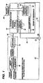
- the single figure of the drawing is a block diagram of an embodiment of the control system of the invention.
- the present invention is based on the fact that it is possible to measure accurately this relative motion and modify a commutation algorithm within a servo controller such that the relative motion between machine base and stator is taken into consideration.
- a resulting modified commutation algorithm will therefore have exact knowledge of the relative position between the actuator's moving element and the actuator's stator and thus be capable of developing optimal commutation so as to achieve maximum trust per given current level.
- an actuator stator 10 is supported on a machine base 12 as described in the above-mentioned co-pending U.S. patent application.
- An encoder scale 14 is affixed to the stator 10 and an encoder readhead 16 is affixed to the machine base 12.
- the encoder scale 14 and the encoder readhead 16 cooperate to generate a signal 18 proportional to the position of the stator 10 with respect to the machine base 12.
- an encoder scale 20 on machine base 12 cooperates with a carriage position feedback readhead 22 to generate a signal 24 proportional to the location of a moving carriage 26 with respect to the machine base 12. It is noted that any other position monitoring devices can be used instead of encoders.
- the signal 18 is subtracted from the signal 24 to generate a signal 28 that becomes an error signal input to a servo controlled commutation algorithm 30.
- Outputs from the servo controller commutation algorithm 30 is amplified by an amplifier 32 to generate a signal 34 to drive the carriage 26 to position accurately the carriage 26 with respect to the machine base 12.
- Initialization of commutation is conducted by standard techniques known to those of ordinary skill in the art. Thereafter, the relative position between the actuator's moving element and the actuator's stator is updated according to feedback from the position feedback devices 16 and 22.
- the present control system allows a carriage to be positioned with respect to a machine base as accurately as it could have been in prior art apparatus in which the stator was rigidly attached to the machine base.
Landscapes
- Engineering & Computer Science (AREA)
- Mechanical Engineering (AREA)
- Human Computer Interaction (AREA)
- Manufacturing & Machinery (AREA)
- Physics & Mathematics (AREA)
- General Physics & Mathematics (AREA)
- Automation & Control Theory (AREA)
- Control Of Linear Motors (AREA)
- Control Of Position Or Direction (AREA)
- Control Of Vehicles With Linear Motors And Vehicles That Are Magnetically Levitated (AREA)
- Soft Magnetic Materials (AREA)
- Iron Core Of Rotating Electric Machines (AREA)
Abstract
Description
- This invention relates to a stator position feedback controller in a system in which a stator is supported for motion with respect to a machine base.
- United States Patent
US-2003/0218398-A1, published 27th November 2003 , entitled "Reaction Force Transfer System" is directed to a precision machine for controlling the position of a work piece relative to a tool. As taught in that patent application, the stator of a linear motor, rather than being rigidly affixed to a machine base, is allowed to move with respect to the machine base. The stator itself is connected to an external frame in a manner to constrain the stator to a single degree of freedom of motion. The decoupling of the stator from being rigidly affixed to the machine base eliminates excessive motion of the machine base that would otherwise be generated by the reaction force as the carriage is accelerated thereby minimizing detrimental side effects of such motion. - In some prior art actuators the electrical control of the actuator requires accurate feedback of the position of the actuator's moving element with respect to the actuator's stator. When, as in the case of an actuator's stator being rigidly connected to a machine base, the feedback source of the moving carriage used for position control can also be used to develop the electrical signal to the actuator. This signal is commonly known as "commutation" based on the manipulation of current through motor phases. The position of the actuator's moving element relative to the actuator's stator is correlated to the electrical controls through some initialization process and from that point on the relative position is continuously updated according to the moving carriage's position feedback source information.
- Because the stator in the patent application noted above is not rigidly connected to the machine base it is free to move relative to the machine base in a direction of thrust. Thus, the relative position between the actuator's moving element and the actuator's stator is not accurately represented by the moving carriage's position feedback source. In some actuators such as linear motors, performance may be degraded because at any given motor current the developed thrust is reduced according to the deviation from exact "commutation" position. This potential problem was discussed in the above noted patent application.
- One possible solution to this problem is to install an additional position feedback device such as an encoder with the encoder readhead attached to the actuator's moving element (or to the moving carriage) and its scale affixed to the actuator's stator. This feedback device would then be used for the purpose of "commutation" alone. Because the encoder scale is rigidly coupled to the actuator's stator, the signal from this feedback device always represents the true relative position between the actuator's moving element (carriage) and the actuator's stator. This solution, however, is expensive because the axis travel maybe long requiring a long encoder scale; in addition, another encoder readhead will have to be mounted to the moving carriage requiring another signal cable and increasing cable management complexity.
-
US-A-4,987,526 discloses a system for moving an object to a desired position quickly, but while minimizing oscillations, using an actuator and a flexural transmission. The system measures to positions of the object and the actuator, and then determines the differences between these positions and the desired final positions. This information is used to determine when and how much the actuator should jerk back on the object. The flexural transmission can include a tensioned wire that is oriented in the direction of movement of the item. -
US-A-2003/218398 discloses a stator position feedback controller having the features of the preamble of claim 1. The present invention is characterized by the features of the characterizing portion of claim 1. Optional features are recited in the dependent claims. - The stator position feedback controller of the invention includes a stator supported for relative motion with respect to a machine base. A first position monitoring device is responsive to position of the stator with respect to the machine base. Suitable position monitoring devices include, for example, encoders and LVDTs. An actuator is provided for moving a carriage through interaction with the stator and a second position monitoring device is responsive to position of the carriage with respect to the machine base. A servo controller responds to an output of the second position monitoring device minus an output of the first position monitoring device to control the position of the carriage with respect to the machine base. In a preferred embodiment, the first position monitoring device has an encoder scale affixed to the stator and a readhead affixed to the machine base. Similarly, in this embodiment the second encoder has an encoder scale affixed to the machine base and a readhead affixed to the actuator. The servo controller comprises a commutation algorithm to control the position of the moving carriage.
- The single figure of the drawing is a block diagram of an embodiment of the control system of the invention.
- As discussed above, degradation in actuator performance can result from an unmeasured motion of the stator relative to the machine base. The present invention is based on the fact that it is possible to measure accurately this relative motion and modify a commutation algorithm within a servo controller such that the relative motion between machine base and stator is taken into consideration. A resulting modified commutation algorithm will therefore have exact knowledge of the relative position between the actuator's moving element and the actuator's stator and thus be capable of developing optimal commutation so as to achieve maximum trust per given current level.
- With reference now to the single figure of the drawing, an
actuator stator 10 is supported on amachine base 12 as described in the above-mentioned co-pending U.S. patent application. Thus, there can be relative motion between thestator 10 and machine base or frame ofreference 12. Anencoder scale 14 is affixed to thestator 10 and anencoder readhead 16 is affixed to themachine base 12. Theencoder scale 14 and the encoder readhead 16 cooperate to generate asignal 18 proportional to the position of thestator 10 with respect to themachine base 12. Similarly, anencoder scale 20 onmachine base 12 cooperates with a carriage position feedback readhead 22 to generate asignal 24 proportional to the location of a movingcarriage 26 with respect to themachine base 12. It is noted that any other position monitoring devices can be used instead of encoders. - As those skilled in the art will appreciate the
signal 18 is subtracted from thesignal 24 to generate asignal 28 that becomes an error signal input to a servo controlledcommutation algorithm 30. Outputs from the servocontroller commutation algorithm 30 is amplified by anamplifier 32 to generate a signal 34 to drive thecarriage 26 to position accurately thecarriage 26 with respect to themachine base 12. Initialization of commutation is conducted by standard techniques known to those of ordinary skill in the art. Thereafter, the relative position between the actuator's moving element and the actuator's stator is updated according to feedback from theposition feedback devices
Claims (3)
- Stator position feedback controller comprising:a stator (10) supported for relative motion with respect to a machine base (12);an actuator for moving a carriage (26) through interaction with the stator (10); anda first position monitoring device responsive to position of the carriage (26) with respect to the machine base (12); andcharacterized by:a second position monitoring device responsive to position of the stator (10) with respect to the machine base (12); anda servo controller responsive to an output of the first positionmonitoring device minus an output of the second position monitoring device to control the position of the carriage (26) with respect to the machine base (12).
- The feedback controller of claim 1 wherein the second position monitoring device is an encoder and has an encoder scale (14) affixed to the stator (10) and a readhead (16) affixed to the machine base (12).
- The feedback controller of claim 1 wherein the first position monitoring device is an encoder and has an encoder scale (20) affixed to the machine base (12) and a readhead (22) affixed to the carriage (26).
Applications Claiming Priority (2)
| Application Number | Priority Date | Filing Date | Title |
|---|---|---|---|
| US10/900,228 US7268504B2 (en) | 2002-05-24 | 2004-07-27 | Stator position feedback controller |
| PCT/US2005/022899 WO2006023078A1 (en) | 2004-07-27 | 2005-06-27 | Stator position feedback controller |
Publications (2)
| Publication Number | Publication Date |
|---|---|
| EP1779207A1 EP1779207A1 (en) | 2007-05-02 |
| EP1779207B1 true EP1779207B1 (en) | 2010-04-28 |
Family
ID=35285490
Family Applications (1)
| Application Number | Title | Priority Date | Filing Date |
|---|---|---|---|
| EP05850084A Expired - Lifetime EP1779207B1 (en) | 2004-07-27 | 2005-06-27 | Stator position feedback controller |
Country Status (7)
| Country | Link |
|---|---|
| US (1) | US7268504B2 (en) |
| EP (1) | EP1779207B1 (en) |
| JP (1) | JP4364280B2 (en) |
| AT (1) | ATE466319T1 (en) |
| CA (1) | CA2574376C (en) |
| DE (1) | DE602005020944D1 (en) |
| WO (1) | WO2006023078A1 (en) |
Family Cites Families (6)
| Publication number | Priority date | Publication date | Assignee | Title |
|---|---|---|---|---|
| US4987526A (en) * | 1989-02-02 | 1991-01-22 | Massachusetts Institute Of Technology | System to provide high speed, high accuracy motion |
| AU3167299A (en) * | 1998-04-09 | 1999-11-01 | Nikon Corporation | Vibration eliminating device and exposure system |
| TW546551B (en) * | 1999-12-21 | 2003-08-11 | Asml Netherlands Bv | Balanced positioning system for use in lithographic apparatus |
| TWI264617B (en) * | 1999-12-21 | 2006-10-21 | Asml Netherlands Bv | Balanced positioning system for use in lithographic apparatus |
| JP4474020B2 (en) * | 2000-06-23 | 2010-06-02 | キヤノン株式会社 | Moving apparatus and exposure apparatus |
| US6844635B2 (en) * | 2002-05-24 | 2005-01-18 | Dover Instrument Corporation | Reaction force transfer system |
-
2004
- 2004-07-27 US US10/900,228 patent/US7268504B2/en not_active Expired - Fee Related
-
2005
- 2005-06-27 JP JP2007522517A patent/JP4364280B2/en not_active Expired - Fee Related
- 2005-06-27 EP EP05850084A patent/EP1779207B1/en not_active Expired - Lifetime
- 2005-06-27 AT AT05850084T patent/ATE466319T1/en not_active IP Right Cessation
- 2005-06-27 CA CA002574376A patent/CA2574376C/en not_active Expired - Fee Related
- 2005-06-27 WO PCT/US2005/022899 patent/WO2006023078A1/en not_active Ceased
- 2005-06-27 DE DE602005020944T patent/DE602005020944D1/en not_active Expired - Lifetime
Also Published As
| Publication number | Publication date |
|---|---|
| WO2006023078A1 (en) | 2006-03-02 |
| US20050067985A1 (en) | 2005-03-31 |
| JP4364280B2 (en) | 2009-11-11 |
| DE602005020944D1 (en) | 2010-06-10 |
| JP2008507061A (en) | 2008-03-06 |
| US7268504B2 (en) | 2007-09-11 |
| CA2574376C (en) | 2010-02-02 |
| ATE466319T1 (en) | 2010-05-15 |
| CA2574376A1 (en) | 2006-03-02 |
| EP1779207A1 (en) | 2007-05-02 |
Similar Documents
| Publication | Publication Date | Title |
|---|---|---|
| EP1120698B1 (en) | Position controller | |
| CA2108430C (en) | Linear motor control system and method | |
| JPH0230522B2 (en) | ||
| EP1505463A2 (en) | Position control device and position control method for machine tools | |
| CN101408764A (en) | Position control device | |
| KR101440702B1 (en) | Parallel drive system | |
| EP1684138B1 (en) | Position control device, measuring device and machining device | |
| JPH11332213A (en) | Vibration reduction control method and device for variable reluctance linear motor | |
| KR20060072136A (en) | Motor control unit | |
| KR100295248B1 (en) | Wire bonding apparatus and control method thereof | |
| JP3194246B2 (en) | XY stage control device | |
| CA2574376C (en) | Stator position feedback controller | |
| JP4171192B2 (en) | Servo control device | |
| JPH08248157A (en) | Stage device | |
| JP2010082711A (en) | Surface mounting device | |
| JP2002215244A (en) | Servo system | |
| JP4636034B2 (en) | Control device for movable table and movable table device including the same | |
| JP2003084839A (en) | Motor control device with overshoot suppression function | |
| JP2011221596A (en) | Positioning device and positioning method for positioning stage | |
| KR0176444B1 (en) | Position control device for XY-stage | |
| JP2004094368A (en) | Control method for servo system and its controller | |
| JP3269198B2 (en) | Position control device | |
| JP2738399B2 (en) | Position control device | |
| KR0160745B1 (en) | Method for twin-x-y robot control | |
| JP2770978B2 (en) | Position control method and positioning device therefor |
Legal Events
| Date | Code | Title | Description |
|---|---|---|---|
| PUAI | Public reference made under article 153(3) epc to a published international application that has entered the european phase |
Free format text: ORIGINAL CODE: 0009012 |
|
| 17P | Request for examination filed |
Effective date: 20070227 |
|
| AK | Designated contracting states |
Kind code of ref document: A1 Designated state(s): AT BE BG CH CY CZ DE DK EE ES FI FR GB GR HU IE IS IT LI LT LU MC NL PL PT RO SE SI SK TR |
|
| 17Q | First examination report despatched |
Effective date: 20070907 |
|
| DAX | Request for extension of the european patent (deleted) | ||
| REG | Reference to a national code |
Ref country code: HK Ref legal event code: DE Ref document number: 1104095 Country of ref document: HK |
|
| GRAP | Despatch of communication of intention to grant a patent |
Free format text: ORIGINAL CODE: EPIDOSNIGR1 |
|
| GRAS | Grant fee paid |
Free format text: ORIGINAL CODE: EPIDOSNIGR3 |
|
| GRAA | (expected) grant |
Free format text: ORIGINAL CODE: 0009210 |
|
| AK | Designated contracting states |
Kind code of ref document: B1 Designated state(s): AT BE BG CH CY CZ DE DK EE ES FI FR GB GR HU IE IS IT LI LT LU MC NL PL PT RO SE SI SK TR |
|
| REG | Reference to a national code |
Ref country code: GB Ref legal event code: FG4D |
|
| REG | Reference to a national code |
Ref country code: CH Ref legal event code: EP |
|
| REG | Reference to a national code |
Ref country code: IE Ref legal event code: FG4D |
|
| REF | Corresponds to: |
Ref document number: 602005020944 Country of ref document: DE Date of ref document: 20100610 Kind code of ref document: P |
|
| REG | Reference to a national code |
Ref country code: CH Ref legal event code: NV Representative=s name: PATENTANWAELTE SCHAAD, BALASS, MENZL & PARTNER AG |
|
| REG | Reference to a national code |
Ref country code: NL Ref legal event code: VDEP Effective date: 20100428 |
|
| LTIE | Lt: invalidation of european patent or patent extension |
Effective date: 20100428 |
|
| PG25 | Lapsed in a contracting state [announced via postgrant information from national office to epo] |
Ref country code: SE Free format text: LAPSE BECAUSE OF FAILURE TO SUBMIT A TRANSLATION OF THE DESCRIPTION OR TO PAY THE FEE WITHIN THE PRESCRIBED TIME-LIMIT Effective date: 20100428 Ref country code: NL Free format text: LAPSE BECAUSE OF FAILURE TO SUBMIT A TRANSLATION OF THE DESCRIPTION OR TO PAY THE FEE WITHIN THE PRESCRIBED TIME-LIMIT Effective date: 20100428 Ref country code: ES Free format text: LAPSE BECAUSE OF FAILURE TO SUBMIT A TRANSLATION OF THE DESCRIPTION OR TO PAY THE FEE WITHIN THE PRESCRIBED TIME-LIMIT Effective date: 20100808 Ref country code: LT Free format text: LAPSE BECAUSE OF FAILURE TO SUBMIT A TRANSLATION OF THE DESCRIPTION OR TO PAY THE FEE WITHIN THE PRESCRIBED TIME-LIMIT Effective date: 20100428 |
|
| PG25 | Lapsed in a contracting state [announced via postgrant information from national office to epo] |
Ref country code: AT Free format text: LAPSE BECAUSE OF FAILURE TO SUBMIT A TRANSLATION OF THE DESCRIPTION OR TO PAY THE FEE WITHIN THE PRESCRIBED TIME-LIMIT Effective date: 20100428 Ref country code: IS Free format text: LAPSE BECAUSE OF FAILURE TO SUBMIT A TRANSLATION OF THE DESCRIPTION OR TO PAY THE FEE WITHIN THE PRESCRIBED TIME-LIMIT Effective date: 20100828 Ref country code: FI Free format text: LAPSE BECAUSE OF FAILURE TO SUBMIT A TRANSLATION OF THE DESCRIPTION OR TO PAY THE FEE WITHIN THE PRESCRIBED TIME-LIMIT Effective date: 20100428 Ref country code: SI Free format text: LAPSE BECAUSE OF FAILURE TO SUBMIT A TRANSLATION OF THE DESCRIPTION OR TO PAY THE FEE WITHIN THE PRESCRIBED TIME-LIMIT Effective date: 20100428 |
|
| PG25 | Lapsed in a contracting state [announced via postgrant information from national office to epo] |
Ref country code: PL Free format text: LAPSE BECAUSE OF FAILURE TO SUBMIT A TRANSLATION OF THE DESCRIPTION OR TO PAY THE FEE WITHIN THE PRESCRIBED TIME-LIMIT Effective date: 20100428 Ref country code: GR Free format text: LAPSE BECAUSE OF FAILURE TO SUBMIT A TRANSLATION OF THE DESCRIPTION OR TO PAY THE FEE WITHIN THE PRESCRIBED TIME-LIMIT Effective date: 20100729 Ref country code: CY Free format text: LAPSE BECAUSE OF FAILURE TO SUBMIT A TRANSLATION OF THE DESCRIPTION OR TO PAY THE FEE WITHIN THE PRESCRIBED TIME-LIMIT Effective date: 20100512 |
|
| PG25 | Lapsed in a contracting state [announced via postgrant information from national office to epo] |
Ref country code: DK Free format text: LAPSE BECAUSE OF FAILURE TO SUBMIT A TRANSLATION OF THE DESCRIPTION OR TO PAY THE FEE WITHIN THE PRESCRIBED TIME-LIMIT Effective date: 20100428 Ref country code: PT Free format text: LAPSE BECAUSE OF FAILURE TO SUBMIT A TRANSLATION OF THE DESCRIPTION OR TO PAY THE FEE WITHIN THE PRESCRIBED TIME-LIMIT Effective date: 20100830 Ref country code: MC Free format text: LAPSE BECAUSE OF NON-PAYMENT OF DUE FEES Effective date: 20100630 Ref country code: EE Free format text: LAPSE BECAUSE OF FAILURE TO SUBMIT A TRANSLATION OF THE DESCRIPTION OR TO PAY THE FEE WITHIN THE PRESCRIBED TIME-LIMIT Effective date: 20100428 |
|
| PG25 | Lapsed in a contracting state [announced via postgrant information from national office to epo] |
Ref country code: BE Free format text: LAPSE BECAUSE OF FAILURE TO SUBMIT A TRANSLATION OF THE DESCRIPTION OR TO PAY THE FEE WITHIN THE PRESCRIBED TIME-LIMIT Effective date: 20100428 Ref country code: CZ Free format text: LAPSE BECAUSE OF FAILURE TO SUBMIT A TRANSLATION OF THE DESCRIPTION OR TO PAY THE FEE WITHIN THE PRESCRIBED TIME-LIMIT Effective date: 20100428 Ref country code: SK Free format text: LAPSE BECAUSE OF FAILURE TO SUBMIT A TRANSLATION OF THE DESCRIPTION OR TO PAY THE FEE WITHIN THE PRESCRIBED TIME-LIMIT Effective date: 20100428 Ref country code: RO Free format text: LAPSE BECAUSE OF FAILURE TO SUBMIT A TRANSLATION OF THE DESCRIPTION OR TO PAY THE FEE WITHIN THE PRESCRIBED TIME-LIMIT Effective date: 20100428 |
|
| PLBE | No opposition filed within time limit |
Free format text: ORIGINAL CODE: 0009261 |
|
| STAA | Information on the status of an ep patent application or granted ep patent |
Free format text: STATUS: NO OPPOSITION FILED WITHIN TIME LIMIT |
|
| REG | Reference to a national code |
Ref country code: FR Ref legal event code: ST Effective date: 20110228 |
|
| GBPC | Gb: european patent ceased through non-payment of renewal fee |
Effective date: 20100728 |
|
| 26N | No opposition filed |
Effective date: 20110131 |
|
| PG25 | Lapsed in a contracting state [announced via postgrant information from national office to epo] |
Ref country code: IE Free format text: LAPSE BECAUSE OF NON-PAYMENT OF DUE FEES Effective date: 20100627 |
|
| PG25 | Lapsed in a contracting state [announced via postgrant information from national office to epo] |
Ref country code: FR Free format text: LAPSE BECAUSE OF NON-PAYMENT OF DUE FEES Effective date: 20100630 |
|
| PG25 | Lapsed in a contracting state [announced via postgrant information from national office to epo] |
Ref country code: GB Free format text: LAPSE BECAUSE OF NON-PAYMENT OF DUE FEES Effective date: 20100728 |
|
| PGFP | Annual fee paid to national office [announced via postgrant information from national office to epo] |
Ref country code: DE Payment date: 20120627 Year of fee payment: 8 Ref country code: CH Payment date: 20120625 Year of fee payment: 8 |
|
| PG25 | Lapsed in a contracting state [announced via postgrant information from national office to epo] |
Ref country code: BG Free format text: LAPSE BECAUSE OF FAILURE TO SUBMIT A TRANSLATION OF THE DESCRIPTION OR TO PAY THE FEE WITHIN THE PRESCRIBED TIME-LIMIT Effective date: 20100428 Ref country code: HU Free format text: LAPSE BECAUSE OF FAILURE TO SUBMIT A TRANSLATION OF THE DESCRIPTION OR TO PAY THE FEE WITHIN THE PRESCRIBED TIME-LIMIT Effective date: 20101029 Ref country code: LU Free format text: LAPSE BECAUSE OF NON-PAYMENT OF DUE FEES Effective date: 20100627 |
|
| PGFP | Annual fee paid to national office [announced via postgrant information from national office to epo] |
Ref country code: IT Payment date: 20120621 Year of fee payment: 8 |
|
| PG25 | Lapsed in a contracting state [announced via postgrant information from national office to epo] |
Ref country code: TR Free format text: LAPSE BECAUSE OF FAILURE TO SUBMIT A TRANSLATION OF THE DESCRIPTION OR TO PAY THE FEE WITHIN THE PRESCRIBED TIME-LIMIT Effective date: 20100428 |
|
| PG25 | Lapsed in a contracting state [announced via postgrant information from national office to epo] |
Ref country code: BG Free format text: LAPSE BECAUSE OF FAILURE TO SUBMIT A TRANSLATION OF THE DESCRIPTION OR TO PAY THE FEE WITHIN THE PRESCRIBED TIME-LIMIT Effective date: 20100728 |
|
| REG | Reference to a national code |
Ref country code: HK Ref legal event code: WD Ref document number: 1104095 Country of ref document: HK |
|
| REG | Reference to a national code |
Ref country code: CH Ref legal event code: PL |
|
| REG | Reference to a national code |
Ref country code: DE Ref legal event code: R119 Ref document number: 602005020944 Country of ref document: DE Effective date: 20140101 |
|
| PG25 | Lapsed in a contracting state [announced via postgrant information from national office to epo] |
Ref country code: LI Free format text: LAPSE BECAUSE OF NON-PAYMENT OF DUE FEES Effective date: 20130630 Ref country code: CH Free format text: LAPSE BECAUSE OF NON-PAYMENT OF DUE FEES Effective date: 20130630 Ref country code: DE Free format text: LAPSE BECAUSE OF NON-PAYMENT OF DUE FEES Effective date: 20140101 |
|
| PG25 | Lapsed in a contracting state [announced via postgrant information from national office to epo] |
Ref country code: IT Free format text: LAPSE BECAUSE OF NON-PAYMENT OF DUE FEES Effective date: 20130627 |