EP1778326B1 - Energy trigger - Google Patents
Energy trigger Download PDFInfo
- Publication number
- EP1778326B1 EP1778326B1 EP05759864A EP05759864A EP1778326B1 EP 1778326 B1 EP1778326 B1 EP 1778326B1 EP 05759864 A EP05759864 A EP 05759864A EP 05759864 A EP05759864 A EP 05759864A EP 1778326 B1 EP1778326 B1 EP 1778326B1
- Authority
- EP
- European Patent Office
- Prior art keywords
- flow
- breathing
- breathing gas
- indicative
- patient
- Prior art date
- Legal status (The legal status is an assumption and is not a legal conclusion. Google has not performed a legal analysis and makes no representation as to the accuracy of the status listed.)
- Expired - Lifetime
Links
Images


Classifications
-
- A—HUMAN NECESSITIES
- A61—MEDICAL OR VETERINARY SCIENCE; HYGIENE
- A61M—DEVICES FOR INTRODUCING MEDIA INTO, OR ONTO, THE BODY; DEVICES FOR TRANSDUCING BODY MEDIA OR FOR TAKING MEDIA FROM THE BODY; DEVICES FOR PRODUCING OR ENDING SLEEP OR STUPOR
- A61M16/00—Devices for influencing the respiratory system of patients by gas treatment, e.g. ventilators; Tracheal tubes
- A61M16/0051—Devices for influencing the respiratory system of patients by gas treatment, e.g. ventilators; Tracheal tubes with alarm devices
-
- A—HUMAN NECESSITIES
- A61—MEDICAL OR VETERINARY SCIENCE; HYGIENE
- A61M—DEVICES FOR INTRODUCING MEDIA INTO, OR ONTO, THE BODY; DEVICES FOR TRANSDUCING BODY MEDIA OR FOR TAKING MEDIA FROM THE BODY; DEVICES FOR PRODUCING OR ENDING SLEEP OR STUPOR
- A61M16/00—Devices for influencing the respiratory system of patients by gas treatment, e.g. ventilators; Tracheal tubes
- A61M16/0057—Pumps therefor
- A61M16/0066—Blowers or centrifugal pumps
- A61M16/0069—Blowers or centrifugal pumps the speed thereof being controlled by respiratory parameters, e.g. by inhalation
-
- A—HUMAN NECESSITIES
- A61—MEDICAL OR VETERINARY SCIENCE; HYGIENE
- A61M—DEVICES FOR INTRODUCING MEDIA INTO, OR ONTO, THE BODY; DEVICES FOR TRANSDUCING BODY MEDIA OR FOR TAKING MEDIA FROM THE BODY; DEVICES FOR PRODUCING OR ENDING SLEEP OR STUPOR
- A61M16/00—Devices for influencing the respiratory system of patients by gas treatment, e.g. ventilators; Tracheal tubes
- A61M16/021—Devices for influencing the respiratory system of patients by gas treatment, e.g. ventilators; Tracheal tubes operated by electrical means
- A61M16/022—Control means therefor
- A61M16/024—Control means therefor including calculation means, e.g. using a processor
-
- A—HUMAN NECESSITIES
- A61—MEDICAL OR VETERINARY SCIENCE; HYGIENE
- A61M—DEVICES FOR INTRODUCING MEDIA INTO, OR ONTO, THE BODY; DEVICES FOR TRANSDUCING BODY MEDIA OR FOR TAKING MEDIA FROM THE BODY; DEVICES FOR PRODUCING OR ENDING SLEEP OR STUPOR
- A61M16/00—Devices for influencing the respiratory system of patients by gas treatment, e.g. ventilators; Tracheal tubes
- A61M16/0003—Accessories therefor, e.g. sensors, vibrators, negative pressure
- A61M2016/0027—Accessories therefor, e.g. sensors, vibrators, negative pressure pressure meter
-
- A—HUMAN NECESSITIES
- A61—MEDICAL OR VETERINARY SCIENCE; HYGIENE
- A61M—DEVICES FOR INTRODUCING MEDIA INTO, OR ONTO, THE BODY; DEVICES FOR TRANSDUCING BODY MEDIA OR FOR TAKING MEDIA FROM THE BODY; DEVICES FOR PRODUCING OR ENDING SLEEP OR STUPOR
- A61M16/00—Devices for influencing the respiratory system of patients by gas treatment, e.g. ventilators; Tracheal tubes
- A61M16/0003—Accessories therefor, e.g. sensors, vibrators, negative pressure
- A61M2016/003—Accessories therefor, e.g. sensors, vibrators, negative pressure with a flowmeter
- A61M2016/0033—Accessories therefor, e.g. sensors, vibrators, negative pressure with a flowmeter electrical
- A61M2016/0036—Accessories therefor, e.g. sensors, vibrators, negative pressure with a flowmeter electrical in the breathing tube and used in both inspiratory and expiratory phase
-
- A—HUMAN NECESSITIES
- A61—MEDICAL OR VETERINARY SCIENCE; HYGIENE
- A61M—DEVICES FOR INTRODUCING MEDIA INTO, OR ONTO, THE BODY; DEVICES FOR TRANSDUCING BODY MEDIA OR FOR TAKING MEDIA FROM THE BODY; DEVICES FOR PRODUCING OR ENDING SLEEP OR STUPOR
- A61M2205/00—General characteristics of the apparatus
- A61M2205/33—Controlling, regulating or measuring
- A61M2205/3375—Acoustical, e.g. ultrasonic, measuring means
-
- A—HUMAN NECESSITIES
- A61—MEDICAL OR VETERINARY SCIENCE; HYGIENE
- A61M—DEVICES FOR INTRODUCING MEDIA INTO, OR ONTO, THE BODY; DEVICES FOR TRANSDUCING BODY MEDIA OR FOR TAKING MEDIA FROM THE BODY; DEVICES FOR PRODUCING OR ENDING SLEEP OR STUPOR
- A61M2205/00—General characteristics of the apparatus
- A61M2205/35—Communication
- A61M2205/3546—Range
- A61M2205/3561—Range local, e.g. within room or hospital
-
- A—HUMAN NECESSITIES
- A61—MEDICAL OR VETERINARY SCIENCE; HYGIENE
- A61M—DEVICES FOR INTRODUCING MEDIA INTO, OR ONTO, THE BODY; DEVICES FOR TRANSDUCING BODY MEDIA OR FOR TAKING MEDIA FROM THE BODY; DEVICES FOR PRODUCING OR ENDING SLEEP OR STUPOR
- A61M2205/00—General characteristics of the apparatus
- A61M2205/50—General characteristics of the apparatus with microprocessors or computers
-
- A—HUMAN NECESSITIES
- A61—MEDICAL OR VETERINARY SCIENCE; HYGIENE
- A61M—DEVICES FOR INTRODUCING MEDIA INTO, OR ONTO, THE BODY; DEVICES FOR TRANSDUCING BODY MEDIA OR FOR TAKING MEDIA FROM THE BODY; DEVICES FOR PRODUCING OR ENDING SLEEP OR STUPOR
- A61M2230/00—Measuring parameters of the user
- A61M2230/04—Heartbeat characteristics, e.g. ECG, blood pressure modulation
-
- A—HUMAN NECESSITIES
- A61—MEDICAL OR VETERINARY SCIENCE; HYGIENE
- A61M—DEVICES FOR INTRODUCING MEDIA INTO, OR ONTO, THE BODY; DEVICES FOR TRANSDUCING BODY MEDIA OR FOR TAKING MEDIA FROM THE BODY; DEVICES FOR PRODUCING OR ENDING SLEEP OR STUPOR
- A61M2230/00—Measuring parameters of the user
- A61M2230/08—Other bio-electrical signals
- A61M2230/10—Electroencephalographic signals
-
- A—HUMAN NECESSITIES
- A61—MEDICAL OR VETERINARY SCIENCE; HYGIENE
- A61M—DEVICES FOR INTRODUCING MEDIA INTO, OR ONTO, THE BODY; DEVICES FOR TRANSDUCING BODY MEDIA OR FOR TAKING MEDIA FROM THE BODY; DEVICES FOR PRODUCING OR ENDING SLEEP OR STUPOR
- A61M2230/00—Measuring parameters of the user
- A61M2230/18—Rapid eye-movements [REM]
-
- A—HUMAN NECESSITIES
- A61—MEDICAL OR VETERINARY SCIENCE; HYGIENE
- A61M—DEVICES FOR INTRODUCING MEDIA INTO, OR ONTO, THE BODY; DEVICES FOR TRANSDUCING BODY MEDIA OR FOR TAKING MEDIA FROM THE BODY; DEVICES FOR PRODUCING OR ENDING SLEEP OR STUPOR
- A61M2230/00—Measuring parameters of the user
- A61M2230/20—Blood composition characteristics
- A61M2230/205—Blood composition characteristics partial oxygen pressure (P-O2)
-
- A—HUMAN NECESSITIES
- A61—MEDICAL OR VETERINARY SCIENCE; HYGIENE
- A61M—DEVICES FOR INTRODUCING MEDIA INTO, OR ONTO, THE BODY; DEVICES FOR TRANSDUCING BODY MEDIA OR FOR TAKING MEDIA FROM THE BODY; DEVICES FOR PRODUCING OR ENDING SLEEP OR STUPOR
- A61M2230/00—Measuring parameters of the user
- A61M2230/30—Blood pressure
-
- A—HUMAN NECESSITIES
- A61—MEDICAL OR VETERINARY SCIENCE; HYGIENE
- A61M—DEVICES FOR INTRODUCING MEDIA INTO, OR ONTO, THE BODY; DEVICES FOR TRANSDUCING BODY MEDIA OR FOR TAKING MEDIA FROM THE BODY; DEVICES FOR PRODUCING OR ENDING SLEEP OR STUPOR
- A61M2230/00—Measuring parameters of the user
- A61M2230/40—Respiratory characteristics
- A61M2230/43—Composition of exhalation
- A61M2230/432—Composition of exhalation partial CO2 pressure (P-CO2)
-
- A—HUMAN NECESSITIES
- A61—MEDICAL OR VETERINARY SCIENCE; HYGIENE
- A61M—DEVICES FOR INTRODUCING MEDIA INTO, OR ONTO, THE BODY; DEVICES FOR TRANSDUCING BODY MEDIA OR FOR TAKING MEDIA FROM THE BODY; DEVICES FOR PRODUCING OR ENDING SLEEP OR STUPOR
- A61M2230/00—Measuring parameters of the user
- A61M2230/40—Respiratory characteristics
- A61M2230/43—Composition of exhalation
- A61M2230/435—Composition of exhalation partial O2 pressure (P-O2)
-
- A—HUMAN NECESSITIES
- A61—MEDICAL OR VETERINARY SCIENCE; HYGIENE
- A61M—DEVICES FOR INTRODUCING MEDIA INTO, OR ONTO, THE BODY; DEVICES FOR TRANSDUCING BODY MEDIA OR FOR TAKING MEDIA FROM THE BODY; DEVICES FOR PRODUCING OR ENDING SLEEP OR STUPOR
- A61M2230/00—Measuring parameters of the user
- A61M2230/50—Temperature
-
- A—HUMAN NECESSITIES
- A61—MEDICAL OR VETERINARY SCIENCE; HYGIENE
- A61M—DEVICES FOR INTRODUCING MEDIA INTO, OR ONTO, THE BODY; DEVICES FOR TRANSDUCING BODY MEDIA OR FOR TAKING MEDIA FROM THE BODY; DEVICES FOR PRODUCING OR ENDING SLEEP OR STUPOR
- A61M2230/00—Measuring parameters of the user
- A61M2230/60—Muscle strain, i.e. measured on the user
Definitions
- the present invention relates to the measurement and control of breathing gas administration into humans, and more specifically, the invention relates to a system for rapid response to changes of patient effort during ventilation of breathing gas.
- Patients suffering from different forms of breathing disorders can be subject to several types of treatments depending on the illness or disorder present.
- Such treatments include surgical procedures, pharmacologic therapy, and non-invasive mechanical techniques.
- Surgical techniques to remedy breathing disorders constitute a considerable risk for the patient and can lead to permanent injury or even mortality.
- Pharmacologic therapy has in general proved disappointing with respect to treating certain breathing disorders, e.g. sleep apnea. It is therefore of interest to find other treatments, preferably non-invasive techniques.
- a mechanical ventilator represents a non-invasive technique for treatment of certain breathing disorders such as ventilatory failure, hypoventilation, and periodic breathing during sleep and awake and in sleep apnea that occurs exclusively during sleep.
- Ventilatory failure includes all forms of insufficient ventilation with respect to metabolic need whether occurring during wake or periods of sleep.
- Hypoventilation and periodic breathing in its most frequently occurring form referred to as Cheyne-Stokes ventilation, may occur periodically or constantly during wake or sleep.
- Conditions associated with hypoventilation, in particular nocturnal hypoventilation include e.g. central nervous system disorders such as stroke, muscular dystrophies, certain congenital conditions, advanced chronic obstructive pulmonary disease (COPD), etc.
- Cheyne-Stokes ventilation or various forms of central apnea are commonly associated with cardiac and circulatory disorders, in particular cardiac failure.
- Ventilatory failure is a potentially life threatening condition.
- the general comorbidity in patients with failing ventilation is considerable.
- the condition is highly disabling in terms of reduced physical capacity, cognitive dysfunction in severe cases and poor quality of life.
- Patients with ventilatory failure therefore experience significant daytime symptoms but in addition, the majority of these cases experience a general worsening of their condition during state changes such as sleep.
- the phenomenon of disordered breathing during sleep, whether occurring as a consequence of ventilatory failure or as a component of sleep apnea in accordance with the description above causes sleep fragmentation. Daytime complications include sleepiness and cognitive dysfunction.
- Severe sleep disordered breathing occurring in other comorbid conditions like obesity, neuromuscular disease, post polio myelitis states, scoliosis or heart failure may be associated with considerable worsening of hypoventilation and compromised blood gas balance.
- Sleep apnea has been associated with cardiovascular complications including coronary heart disease, myocardial infarction, stroke, arterial hypertension, thrombosis, and cardiac arrhythmia. It is therefore of both immediate and long-term interest to reduce the exposure to sleep disordered breathing.
- CPAP continuous positive airway pressure
- Bi-level CPAP provides increased comfort for most patients and not infrequently, an improved clinical response.
- Bi-level CPAP provides two pressure levels, Inspiratory Positive Airway Pressure (IPAP) and Expiratory Positive Airway Pressure (EPAP). IPAP is administered during the inhalation phase while EPAP is given during the exhalation phase.
- IIPAP Inspiratory Positive Airway Pressure
- EPAP Expiratory Positive Airway Pressure
- WO9423780 illustrates a solution for controlling sleep disorder breathing and uses pressure transducers for monitoring pressures which are analyzed for detecting sleep disorder events. In this solution leakage is of no importance since the system uses a complex analysis of the pressure measurements and the curve forms received together with modulation of compressor output.
- EP0722747 a solution for treatment of sleep disorder using a CPAP apparatus is presented. This solution handles leakages in the system by detecting them and waiting for the leak to be removed before adjusting the pressure.
- CPAP bi-level continuous positive airway pressure
- the dependency of calculating the gas flow leakage will be of no importance.
- the effort made by the patient is equal to the amount of gas withdrawn from the breathing tube, if the leakage during inhalation is constant. Since the time from inhalation start to the triggering point lies in the region of 50 - 100 msec the leakage can be considered as constant.
- the patient effort can then be calculated as the kinetic energy term in Bernoulli's equation for fluid medias.
- the actual work for the Inspiration trigger can be calculated and presented as well.
- the method can also be used in weaning processes and in exercising patients with reduced breathing capacity.
- a mechanical ventilator apparatus for use in delivering of breathing gas to humans, the ventilator comprises:
- the apparatus may be arranged so that the processing unit is arranged to apply the flow curve to a derivative procedure deriving the energy content and compare an output from the derivative procedure with at least one predetermined trigger level.
- the derivative may be indicative of the inhalation start phase or exhalation phase.
- a method for facilitating breathing in connection with a mechanical ventilator arrangement comprising the steps of:
- a system for facilitating breathing when using a mechanical ventilator arrangement comprising:
- the processing unit may be arranged to apply the flow curve to a derivative procedure in order to deduce the energy content and compare an output from the derivative procedure with at least one predetermined trigger level.
- the processing unit may be further arranged to obtain a pressure signal and using this pressure signal in the process of determining the energy content.
- a computer program for controlling a mechanical ventilator apparatus wherein the program operate on signals obtained from at least one sensing means for measuring flow of breathing gas to a patient, the program determines if a trigger level has been reached by data indicative of energy of breathing obtained from the flow measurement , and the program transmits control signals to a mechanical ventilator in response if the trigger level has been reached in order to control the supply of breathing gas.
- a ventilation system comprise a mechanical ventilator 4 supplying pressurized breathing gas, tubing 3 for guiding breathing gas to the patient 1, a breathing mask 2 or similar for administrating the breathing gas to the patient 1, sensing means 5, 6, 7, 8, 9 and 10 for determining the physiological status of the patient 1.
- the number of sensors connected to the mechanical ventilator may be one or more; however, in a preferred embodiment of the present invention at least one sensor is necessary: a breathing gas flow measurement which may be located essentially anywhere along the breathing gas tubing or in the mask.
- a mechanical ventilator 4 is supplying breathing gas for instance as a positive airway pressure via a tubing 3 and through a mask 2 to a patient 1.
- the mask 2 can be a face mask 2 covering both the mouth and nose or a nasal mask covering only the nose or nostrils depending on the patients needs. It can also be a hood covering the complete head or body of the patient.
- the breathing gas may be of any suitable gas composition for breathing purposes as understood by the person skilled in the art, the composition may depend on the physiological status of the patient.
- These input parameters may be for instance flow or pressure signals, data obtained from EEG, EMG, EOG, and ECG measurements, O 2 and/or CO 2 measurements in relation to the patient, body temperature, blood pressure, SpO2 (oxygen saturation), eye movements, and sound measurements. It should be understood that the invention is not limited to the above mentioned input parameters but other input parameters may be used.
- Fig. 1 not all sensors 5, 6, 7, 8, 9, and 10 and sensor connection means 5a, 6a, 7a, 8a, and 9a are depicted, only a subset is shown in order to illustrate a schematical view of the system and the depicted locations are only given as examples and are in no way limiting to the invention, e.g. the flow signal may be measured at either the mask location or close to the mechanical ventilator or at both locations in order to deduce a differential signal if this is required.
- the flow sensor 10 may be located at several different positions, e.g. in the breathing air tubing 3 at any suitable position, such as close to the mechanical ventilator apparatus (or even within the ventilator housing) or in the vicinity of the mask.
- the flow is used in the process and thus is the only parameter measured.
- the pressure value is used in the process together with the flow data and thus also a pressure measurement is used as well.
- the flow and pressure signals may be used in the process depending on the algorithm used for determining an energy content of the obtained signals (as will be discussed in more detail below).
- the input data is supplied to a processing unit 11 comprising at least computational means 201.
- the computational or processing means 201 analyses the measured data, preferably data from the flow measurement, according to an appropriate algorithm or algorithms (to be discussed in detail below) in order to determine an appropriate response and send control signal or signals to a mechanical ventilator unit 12.
- This mechanical ventilator unit 12 may be a fan 12 arranged to deliver appropriate amounts of breathing gas at specified and controlled pressure levels.
- the mechanical ventilator device 4 there may also comprise a data storage unit 202 for post analysis and inspection and also a connection for an external nonvolatile memory device, like for instance a memory device using a USB connection, an external hard drive, a floppy disk, a CD-ROM writer, a DVD writer, a Memorystick, a Compact Flash memory, a Secure Digital memory, an xD-Picture memory card, or a Smart Media memory card.
- an external nonvolatile memory device like for instance a memory device using a USB connection, an external hard drive, a floppy disk, a CD-ROM writer, a DVD writer, a Memorystick, a Compact Flash memory, a Secure Digital memory, an xD-Picture memory card, or a Smart Media memory card.
- the mechanical ventilator may also have input means (not shown) for manually setting control parameters and other parameters necessary for the operation of the device.
- the communication means can be of a serial type like for instance according to the standards RS232, RS485, USB, Ethernet, or Firewire, or of a parallel type like for instance according to the standards Centronics, ISA, PCI, or GPIB/HPIB. It may also be any wireless system of the standards in the IEEE 802.11 series, HiperLAN, Bluetooth, IR, GSM, GPRS, or UMTS, or any other appropriate fixed or wireless communication system capable of transmitting measurement data. It can also be of any proprietary non-standardized communication formats, whether it is wireless or wired.
- the ventilator device 4 may also have display means (not shown) for displaying measured data and obtained response parameters for use by a physician, other medical personnel, or the patient.
- the display means may be of any normal type as appreciated by a person skilled in the art. The data is displayed with such a high rate that a real time feedback is provided to a person monitoring the ventilator characteristics and function for immediate feedback and control.
- the system responds to patient breathing changes by measuring the breathing effort the patient puts into the system. This measurement may be accomplished by calculating the kinetic energy term in Bernoulli's theorem for an ideal gas at a measuring point in the breathing gas supply system comprising the mechanical ventilator 4, the tube 3, and the mask 2 (or even inside the patient 1).
- the first term (p) is a so called "work” term
- the second term (1 ⁇ 2 ⁇ V 2 ) is a so called “kinetic” energy term
- the final term ( ⁇ g h) is a so called “potential” energy term.
- the third term in Eq. 3 (1 ⁇ 2 ⁇ 2 ⁇ V 2 2 ) is the patient "added energy" term.
- This change of energy output proportional to the effort by the patient may be measured and calculated at the energy input 301 via, for example, a derivative procedure.
- Fig. 4 a typical example of a flow measurement 401 from a mechanical ventilator system is shown.
- the flow curve derivative 402 indicative of the energy and a trigger level 403 are also depicted.
- the energy term increases significantly and when the energy term pass the threshold level the system is triggered to respond to the change of effort, this may be called Inspiratory triggering.
- Inspiratory triggering Inspiratory triggering.
- the system may respond to the exhalation phase of the breathing cycle, which may be called Expiratory triggering (some times called expiration termination criteria).
- Expiratory triggering some times called expiration termination criteria.
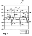
- the flow curve will of course be opposite to the inhalation phase and correspondingly the energy term will also be opposite. This may be seen in Fig. 5 , wherein both inhalation and exhalation phases of the breathing cycle are demonstrated.
- a flow measurement curve 510, a processed energy curve 520, and a trigger level 530 is depicted.
- the rise of the inhalation phases are marked with 501, 502, and 503 while corresponding energy terms are marked 504, 505, and 506.
- exhalation phases are marked with 507, 508, and 509 with the corresponding energy terms marked as 511, 512, and 513.
- a trigger level 530 is set in order to illustrate that at some point the energy curve 520 will reach this trigger level 530.
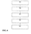
- FIG. 6 A method for using the above mentioned procedure is illustrated in Fig. 6 .
- the method comprises the following steps:
- breathing disorders include, but are not limited to, breathing disorders during sleep, obstructive lung diseases (COPD), neuromuscular disorders, neurological disorders, chest wall disorders, and more.
- COPD obstructive lung diseases
Landscapes
- Health & Medical Sciences (AREA)
- Emergency Medicine (AREA)
- Pulmonology (AREA)
- Engineering & Computer Science (AREA)
- Anesthesiology (AREA)
- Biomedical Technology (AREA)
- Heart & Thoracic Surgery (AREA)
- Hematology (AREA)
- Life Sciences & Earth Sciences (AREA)
- Animal Behavior & Ethology (AREA)
- General Health & Medical Sciences (AREA)
- Public Health (AREA)
- Veterinary Medicine (AREA)
- Measurement Of The Respiration, Hearing Ability, Form, And Blood Characteristics Of Living Organisms (AREA)
Abstract
Description
- The present invention relates to the measurement and control of breathing gas administration into humans, and more specifically, the invention relates to a system for rapid response to changes of patient effort during ventilation of breathing gas.
- Patients suffering from different forms of breathing disorders can be subject to several types of treatments depending on the illness or disorder present. Such treatments include surgical procedures, pharmacologic therapy, and non-invasive mechanical techniques. Surgical techniques to remedy breathing disorders constitute a considerable risk for the patient and can lead to permanent injury or even mortality. Pharmacologic therapy has in general proved disappointing with respect to treating certain breathing disorders, e.g. sleep apnea. It is therefore of interest to find other treatments, preferably non-invasive techniques.
- A mechanical ventilator represents a non-invasive technique for treatment of certain breathing disorders such as ventilatory failure, hypoventilation, and periodic breathing during sleep and awake and in sleep apnea that occurs exclusively during sleep. Ventilatory failure includes all forms of insufficient ventilation with respect to metabolic need whether occurring during wake or periods of sleep. Hypoventilation and periodic breathing, in its most frequently occurring form referred to as Cheyne-Stokes ventilation, may occur periodically or constantly during wake or sleep. Conditions associated with hypoventilation, in particular nocturnal hypoventilation include e.g. central nervous system disorders such as stroke, muscular dystrophies, certain congenital conditions, advanced chronic obstructive pulmonary disease (COPD), etc. Cheyne-Stokes ventilation or various forms of central apnea are commonly associated with cardiac and circulatory disorders, in particular cardiac failure.
- Ventilatory failure is a potentially life threatening condition. The general comorbidity in patients with failing ventilation is considerable. The condition is highly disabling in terms of reduced physical capacity, cognitive dysfunction in severe cases and poor quality of life. Patients with ventilatory failure therefore experience significant daytime symptoms but in addition, the majority of these cases experience a general worsening of their condition during state changes such as sleep. The phenomenon of disordered breathing during sleep, whether occurring as a consequence of ventilatory failure or as a component of sleep apnea in accordance with the description above causes sleep fragmentation. Daytime complications include sleepiness and cognitive dysfunction. Severe sleep disordered breathing occurring in other comorbid conditions like obesity, neuromuscular disease, post polio myelitis states, scoliosis or heart failure may be associated with considerable worsening of hypoventilation and compromised blood gas balance. Sleep apnea has been associated with cardiovascular complications including coronary heart disease, myocardial infarction, stroke, arterial hypertension, thrombosis, and cardiac arrhythmia. It is therefore of both immediate and long-term interest to reduce the exposure to sleep disordered breathing.
- Recent advancement in mechanical non-invasive ventilator techniques includes administration of continuous positive airway pressure (CPAP) in different forms of sleep disordered breathing. During CPAP administration an elevated airway pressure is maintained throughout the breathing phase during a period coinciding with sleep. In sleep apnea this procedure may provide appropriate stabilization of the upper airway thereby preventing collapse. This, so called mono-level CPAP therapy, provides an almost identical pressure during inhalation and exhalation. Not only may CPAP be uncomfortable for the patient due to a sensed increased work of breathing during ventilation, specifically expiration. Some forms of apnea, mainly including those of central origin, and most forms of hypoventilation are only poorly controlled by CPAP. A more recently developed bi-level CPAP system administers different pressure levels during inhalation and exhalation. Bi-level CPAP provides increased comfort for most patients and not infrequently, an improved clinical response. Bi-level CPAP provides two pressure levels, Inspiratory Positive Airway Pressure (IPAP) and Expiratory Positive Airway Pressure (EPAP). IPAP is administered during the inhalation phase while EPAP is given during the exhalation phase.
- In ventilation treatment it is crucial that the inspiratory and expiratory phases synchronize with the patient efforts. A system that does not comply with patient efforts, creates an air trapping situation and increase discomfort for the patient as well as considerably increasing the possibility of anxiety for the patient.
- Several different systems have been developed to make mechanical ventilators operate in accordance with patient rhythms. One key component in such systems is the ability to sense the patient rhythm or breathing phases. The early systems used pressure sensing devices to detect the pressure drop when patient tried to inhale. These systems however led to that the patient had to make a higher effort due to that the breathing tubing had to be depressurised before the trigger detection could be made, leaving the patient with a high effort level.
- Succeeding the pressure systems was flow based systems which was based on a flow sensing mechanism. This was done by sensing the flow of gas entering and leaving the patient. There have been a number of methods of measuring the instantaneous and average gas flow described in literature to calculate the inspiratory and expiratory triggering points. One of the major problems in flow sensor mechanisms is that the system has to calculate the actual leakage from mask, mouth, and other leakages in the breathing circuits, that can lead to machine induced inspiratory triggering problems and missed inspiratory trigger. If this occurs it will result in that the ventilator is not responding to patient inspiratory and expiratory phases correctly and a high discomfort for the patient.
- One system addressing pressure based measurements is provided in
WO9423780 WO9423780 - In
EP0722747 a solution for treatment of sleep disorder using a CPAP apparatus is presented. This solution handles leakages in the system by detecting them and waiting for the leak to be removed before adjusting the pressure. - It is an object of the present invention to provide a system that remedies the above mentioned problems and provide an improved breathing gas ventilator solution for use in conjunction with ventilatory disorders, such as for instance as a bi-level continuous positive airway pressure (CPAP) method.
- By measuring the actual patient effort to detect an inspiratory trigger the dependency of calculating the gas flow leakage will be of no importance. When the patient inhales, the effort made by the patient is equal to the amount of gas withdrawn from the breathing tube, if the leakage during inhalation is constant. Since the time from inhalation start to the triggering point lies in the region of 50 - 100 msec the leakage can be considered as constant.
- The patient effort can then be calculated as the kinetic energy term in Bernoulli's equation for fluid medias. By measuring the kinetic energy which is proportional to the patient effort the actual work for the Inspiration trigger can be calculated and presented as well. The method can also be used in weaning processes and in exercising patients with reduced breathing capacity.
- In a preferred embodiment of the present invention a mechanical ventilator apparatus for use in delivering of breathing gas to humans is provided, the ventilator comprises:
- a ventilator arrangement;
- a processing unit; and
- input means for obtaining sensor signals indicative of at least breathing gas flow;
- wherein the processing unit is arranged to analyse the flow signals with respect to energy content, trigger a response if the energy content reaches a trigger level, and regulating a supply of breathing gas in accordance with the reached trigger level.
- The apparatus may be arranged so that the processing unit is arranged to apply the flow curve to a derivative procedure deriving the energy content and compare an output from the derivative procedure with at least one predetermined trigger level. The derivative may be indicative of the inhalation start phase or exhalation phase.
- In another aspect of the present invention, a method for facilitating breathing in connection with a mechanical ventilator arrangement is provided, the method comprising the steps of:
- measuring a breathing gas flow;
- processing the breathing gas flow for energy content;
- determining if the energy content has reached a trigger level; and
- responding to the reached trigger level by changing control signals for the mechanical ventilator, the control signals controls the supply of breathing gas.
- The processing unit may be applying the flow curve to a derivative procedure in order to deduce the energy content and comparing an output from the derivative procedure with at least one predetermined trigger level. The processing unit may be further arranged to obtain a pressure signal and using this pressure signal in the process of determining the energy content.
- Yet another preferred embodiment of the present invention, a system for facilitating breathing when using a mechanical ventilator arrangement is provided, comprising:
- at least one sensing means for measuring flow of breathing gas to a patient;
- a breathing gas tubing and breathing gas distribution means;
- a mechanical ventilator apparatus; and
- a processing unit;
- wherein the processing unit is arranged to process data obtained from the sensing means for measuring flow of breathing gas, to determine when a trigger level is reached by data indicative of energy of breathing obtained from the flow measurements, and respond to the reached trigger level by changing control signals controlling a supply of breathing gas in the mechanical ventilator apparatus.
- In the system the processing unit may be arranged to apply the flow curve to a derivative procedure in order to deduce the energy content and compare an output from the derivative procedure with at least one predetermined trigger level. The processing unit may be further arranged to obtain a pressure signal and using this pressure signal in the process of determining the energy content.
- Another embodiment of the present invention, a computer program for controlling a mechanical ventilator apparatus is provided, wherein the program operate on signals obtained from at least one sensing means for measuring flow of breathing gas to a patient, the program determines if a trigger level has been reached by data indicative of energy of breathing obtained from the flow measurement , and the program transmits control signals to a mechanical ventilator in response if the trigger level has been reached in order to control the supply of breathing gas.
- The computer program may further be arranged to apply the flow curve to a derivative procedure deducing the energy content and compare an output from the derivative procedure with at least one predetermined trigger level. The derivative procedure may be indicative of the inhalation rise phase or the exhalation fall phase. The computer program mat be further arranged to obtain a pressure signal and using this pressure signal in the process of determining the energy content.
- In the following the invention will be described in a non-limiting way and in more detail with reference to exemplary embodiments illustrated in the enclosed drawings, in which:
-
Fig. 1 is a schematic depiction of a ventilatory system according to the present invention. -
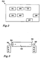
Fig. 2 is a schematic block diagram of a ventilator apparatus according to the present invention. -
Fig. 3 is a schematic diagram of air flow tubing. -
Fig. 4 is a schematical example of a measured flow curve with corresponding energy curve according to the present invention. -
Fig. 5 is another schematic example of flow curve and corresponding energy curve according to the present invention. -
Fig. 6 is a schematic illustration of a method according to the present invention. - In
Fig. 1 a schematic mechanical ventilation system used for the treatment of hypoventilation disorders is depicted. A ventilation system comprise amechanical ventilator 4 supplying pressurized breathing gas, tubing 3 for guiding breathing gas to thepatient 1, abreathing mask 2 or similar for administrating the breathing gas to thepatient 1, sensing means 5, 6, 7, 8, 9 and 10 for determining the physiological status of thepatient 1. The number of sensors connected to the mechanical ventilator may be one or more; however, in a preferred embodiment of the present invention at least one sensor is necessary: a breathing gas flow measurement which may be located essentially anywhere along the breathing gas tubing or in the mask. Amechanical ventilator 4 is supplying breathing gas for instance as a positive airway pressure via a tubing 3 and through amask 2 to apatient 1. Themask 2 can be aface mask 2 covering both the mouth and nose or a nasal mask covering only the nose or nostrils depending on the patients needs. It can also be a hood covering the complete head or body of the patient. - The breathing gas may be of any suitable gas composition for breathing purposes as understood by the person skilled in the art, the composition may depend on the physiological status of the patient.
- The pressure or flow from the
ventilator 4 is controlled by aprocessing unit 11 as shown inFig. 1 . Theprocessing unit 11 may involve a computer program that measures one orseveral input parameters patient 1 describing the physiological status of the patient and pressure/flow data indicative of breathing gas system configuration and status. Data indicative of patient status is obtained usingsensors processing unit 11 via connection means 5a, 6a, 7a, 8a, and 9a (connection means forsensor 10 is not depicted inFig. 1 since the sensor may be placed at several different locations, such as inside the ventilator apparatus). These input parameters may be for instance flow or pressure signals, data obtained from EEG, EMG, EOG, and ECG measurements, O2 and/or CO2 measurements in relation to the patient, body temperature, blood pressure, SpO2 (oxygen saturation), eye movements, and sound measurements. It should be understood that the invention is not limited to the above mentioned input parameters but other input parameters may be used. InFig. 1 not allsensors - The
flow sensor 10 may be located at several different positions, e.g. in the breathing air tubing 3 at any suitable position, such as close to the mechanical ventilator apparatus (or even within the ventilator housing) or in the vicinity of the mask. - In a preferred embodiment of the present invention only the flow is used in the process and thus is the only parameter measured. However, in another preferred embodiment of the present invention also the pressure value is used in the process together with the flow data and thus also a pressure measurement is used as well. However it should be appreciated by the person skilled in the art that more signals then the flow and pressure signals may be used in the process depending on the algorithm used for determining an energy content of the obtained signals (as will be discussed in more detail below).
- The input data is supplied to a
processing unit 11 comprising at leastcomputational means 201. The computational or processing means 201 analyses the measured data, preferably data from the flow measurement, according to an appropriate algorithm or algorithms (to be discussed in detail below) in order to determine an appropriate response and send control signal or signals to amechanical ventilator unit 12. Thismechanical ventilator unit 12 may be afan 12 arranged to deliver appropriate amounts of breathing gas at specified and controlled pressure levels. - The
mechanical ventilator device 4 there may also comprise adata storage unit 202 for post analysis and inspection and also a connection for an external nonvolatile memory device, like for instance a memory device using a USB connection, an external hard drive, a floppy disk, a CD-ROM writer, a DVD writer, a Memorystick, a Compact Flash memory, a Secure Digital memory, an xD-Picture memory card, or a Smart Media memory card. These are only given as examples, and are not limiting for the invention, many more external memory devices may be used in the invention as appreciated by the person skilled in the art. - The mechanical ventilator may also have input means (not shown) for manually setting control parameters and other parameters necessary for the operation of the device.
- Through a communication means 207 it is possible to communicate with the
device 4 to and from an external computational device for retrieving data and results for later analysis and/or inspection. The communication means can be of a serial type like for instance according to the standards RS232, RS485, USB, Ethernet, or Firewire, or of a parallel type like for instance according to the standards Centronics, ISA, PCI, or GPIB/HPIB. It may also be any wireless system of the standards in the IEEE 802.11 series, HiperLAN, Bluetooth, IR, GSM, GPRS, or UMTS, or any other appropriate fixed or wireless communication system capable of transmitting measurement data. It can also be of any proprietary non-standardized communication formats, whether it is wireless or wired. - The
ventilator device 4 may also have display means (not shown) for displaying measured data and obtained response parameters for use by a physician, other medical personnel, or the patient. The display means may be of any normal type as appreciated by a person skilled in the art. The data is displayed with such a high rate that a real time feedback is provided to a person monitoring the ventilator characteristics and function for immediate feedback and control. - In a preferred embodiment of the present invention, the system responds to patient breathing changes by measuring the breathing effort the patient puts into the system. This measurement may be accomplished by calculating the kinetic energy term in Bernoulli's theorem for an ideal gas at a measuring point in the breathing gas supply system comprising the
mechanical ventilator 4, the tube 3, and the mask 2 (or even inside the patient 1). - The basis behind the process may be illustrated by the known Bernoullis theorem for an ideal gas flowing at speed V:

Fig. 3 , wherein a flow of gas from a ventilator device enters the breathing gas tubing 3 and exits in themask 2 located close to thepatient 1, the above equation may then be rewritten due to the fact that according to Bernoullis theorem the equation must be equal at the two ends of the tubing 3. This gives the equality:
- Returning now to the interpretation of Eq. 1, the first term (p) is a so called "work" term, the second term (½ ρ V2) is a so called "kinetic" energy term, and the final term (ρ g h) is a so called "potential" energy term. When a patient inhales, the kinetic energy term in the system is increased:

- The third term in Eq. 3 (½ Δρ2 ΔV2 2) is the patient "added energy" term. This change of energy output proportional to the effort by the patient may be measured and calculated at the
energy input 301 via, for example, a derivative procedure. InFig. 4 a typical example of aflow measurement 401 from a mechanical ventilator system is shown. In the illustration the flow curve derivative 402 indicative of the energy and atrigger level 403 are also depicted. As can be seen infigure 4 during the rise of the flow curve the energy term increases significantly and when the energy term pass the threshold level the system is triggered to respond to the change of effort, this may be called Inspiratory triggering. In such a way it is possible for the system to respond quickly and reduce the effort for the patient, while at the same time increasing the well being for the patient and lowering the risk of causing the patient anxiety. - In a similar fashion the system may respond to the exhalation phase of the breathing cycle, which may be called Expiratory triggering (some times called expiration termination criteria). However, the flow curve will of course be opposite to the inhalation phase and correspondingly the energy term will also be opposite. This may be seen in
Fig. 5 , wherein both inhalation and exhalation phases of the breathing cycle are demonstrated. - In
Fig. 5 aflow measurement curve 510, a processedenergy curve 520, and atrigger level 530 is depicted. The rise of the inhalation phases are marked with 501, 502, and 503 while corresponding energy terms are marked 504, 505, and 506. In a similar fashion exhalation phases are marked with 507, 508, and 509 with the corresponding energy terms marked as 511, 512, and 513. As can be seen during the start of theinhalation phase energy term Fig. 5 atrigger level 530 is set in order to illustrate that at some point theenergy curve 520 will reach thistrigger level 530. When aninspiration trigger distribution system 2 and 3. If anexpiration trigger distribution system 2 and 3. - Care must of course be taken in setting the threshold for where a response should be triggered in order to ensure that no false triggers are given. For the same purpose care should also be taken in how sampled data is processed, e.g. filtering or averaging functions, to reduce noise and other external or internal signal disturbances. It should be appreciated by the person skilled in the art that many types of signal processing means may be utilized in order to improve signal quality as may be found in the standard tools of the trade, such as lowpass filtering techniques or other filtering solutions, different averaging solutions, and other more complex signal processing steps such as fourier analysis. These different "noise" reducing solutions may be implemented either as hardware solutions in the signal path or as software solutions after sampling the signals. THe software solutions may be implemented in the processing unit of the ventilator apparatus of as a separate signal sampling unit (not shown) preprocessing data.
- The ventilator apparatus may have hardware or software means (not shown) for adjusting trigger levels for both inhalation and exhalation phases separately.
- A method for using the above mentioned procedure is illustrated in
Fig. 6 . The method comprises the following steps: - Periodically acquiring 601 sampled
input parameters - measuring a breathing gas
flow sensor signal 602; - deriving an energy term from said flow sensor signal using a
derivate procedure 603; - detecting if the energy term pass through a
predtermined threshold level 604; and - triggering a response from the ventilator upon such a
threshold detection 605 be changing control signals for controlling the breathing gas supply in the ventilator apparatus. - There are many types of ventilation modes where the above described method and apparatus may find its application including but not limited to:
- 1. Continuous positive airway pressure (CPAP),
- 2. Synchronized intermittent mandatory ventilation (SIMV),
- 3. Assist control mechanical ventilation (ACMV),
- 4. Pressure control ventilation (PCV),
- 5. Pressure support ventilation (PSV),
- 6. Proportional assist ventilation (PAV), and
- 7. Volume assured pressure support (VAPS)
- The system may also be used for exercising patients or healthy persons in order to increase their lung capacity which has been reduced for some reason, e.g. after some surgical procedure, accident, medical illness. By exercising, it is possible to reduce risks for patients with reduced breathing capacities. It may also be possible to use the method in weaning processes wherein patients connected to a respirator train with a system according to the present invention in order to remove the need for the respirator. This is a gradual process where the patient's diaphragm is trained until the patient is strong enough to breathe without the help from a respirator.
- These kinds of methods and devices are often used for treating disturbed breathing during for instance sleep either in the home or in a clinical environment. The methods and devices described above within the scope of the invention may also be used for treatment of many other different forms of ventilatory failure events or hypoventilation events, and treatment may be done both at home and in the clinical environment. Examples of groups of breathing disorders include, but are not limited to, breathing disorders during sleep, obstructive lung diseases (COPD), neuromuscular disorders, neurological disorders, chest wall disorders, and more.
- The above mentioned and described embodiments are only given as examples and should not be limiting to the present invention. Other solutions, uses, objectives, and functions within the scope of the invention as claimed in the below described patent claims should be apparent for the person skilled in the art.
Claims (10)
- A mechanical ventilator apparatus (4) for supplying breathing gas to humans (1), the ventilator comprise:- a ventilator arrangement (4);- a processing unit (201); and- input means for obtaining signals from sensors (5, 6, 7, 8, 9, 10) indicative of at least breathing gas flow;characterized in that said processing unit (201) is arranged to analyze said flow signal with respect to kinetic energy content (402, 520), trigger a response if said kinetic energy content (402, 520) reaches a trigger level (403, 530), and to regulate a supply of said breathing gas according to said reached trigger level.
- The apparatus according to claim 1, wherein said processing unit (201) is arranged to apply said flow signal to a derivative procedure in order to deduce said kinetic energy content and compare an output from said derivative procedure with at least one predetermined trigger level (403, 530).
- The apparatus according to claim 2, wherein said derivative output is indicative of the inhalation start phase (501, 502, 503).
- The apparatus according to claim 2, wherein said derivative output is indicative of the exhalation start phase (507, 508, 509).
- The apparatus according to claim 1, further comprising input means for obtaining a signal indicative of pressure, used in said analysis for kinetic energy content together with said signal indicative of breathing gas flow.
- A computer program for controlling a mechanical ventilator apparatus,
wherein said program operate on signals (401, 510) obtained from at least one sensing means for measuring flow of breathing gas to a patient (1), characterized in that said program is arranged to determine if a trigger level (403, 530) has been reached by data indicative of kinetic energy (402, 520) of breathing derived from said flow measurement (401, 51.0), and said program is arranged to transmit control signals, for controlling a supply of breathing gas, to said mechanical ventilator in response if said trigger level has been reached. - The computer program according to claim 6, wherein said computer program is arranged to apply said flow signal (401, 510) to a derivative procedure in order to deduce said kinetic energy content and compare an output (402, 520) from said derivative procedure with at least one predetermined trigger level (403, 530).
- The computer program according to claim 7, wherein said output from said derivative procedure is indicative of the inhalation rise phase (501, 502, 503)
- The computer program according to claim 7, wherein said output from said derivative procedure is indicative of the exhalation fall phase (507, 508, 509).
- The computer program according to claim 6, further using data obtained from measurement of breathing gas pressure together with flow measurements in determining kinetic energy content.
Applications Claiming Priority (3)
| Application Number | Priority Date | Filing Date | Title |
|---|---|---|---|
| SE0401810A SE0401810D0 (en) | 2004-07-08 | 2004-07-08 | Energy trigger |
| US61013704P | 2004-09-15 | 2004-09-15 | |
| PCT/EP2005/006881 WO2006005433A1 (en) | 2004-07-08 | 2005-06-27 | Energy trigger |
Publications (2)
| Publication Number | Publication Date |
|---|---|
| EP1778326A1 EP1778326A1 (en) | 2007-05-02 |
| EP1778326B1 true EP1778326B1 (en) | 2011-05-25 |
Family
ID=34972380
Family Applications (1)
| Application Number | Title | Priority Date | Filing Date |
|---|---|---|---|
| EP05759864A Expired - Lifetime EP1778326B1 (en) | 2004-07-08 | 2005-06-27 | Energy trigger |
Country Status (3)
| Country | Link |
|---|---|
| US (1) | US8910632B2 (en) |
| EP (1) | EP1778326B1 (en) |
| WO (1) | WO2006005433A1 (en) |
Families Citing this family (25)
| Publication number | Priority date | Publication date | Assignee | Title |
|---|---|---|---|---|
| DE102004006396B4 (en) * | 2004-02-10 | 2021-11-04 | Löwenstein Medical Technology S.A. | Device for ventilation and method for controlling a ventilator |
| EP1778325B1 (en) * | 2004-07-08 | 2010-07-28 | Breas Medical AB | Delta flow pressure regulator |
| US8015972B2 (en) * | 2006-01-03 | 2011-09-13 | Shahzad Pirzada | System, device and process for remotely controlling a medical device |
| EP2035070B1 (en) | 2006-06-30 | 2019-10-30 | Breas Medical AB | Energy relief control in a mechanical ventilator |
| WO2009012599A1 (en) * | 2007-07-26 | 2009-01-29 | Uti Limited Partnership | Transient intervention for modifying the breathing of a patient |
| CN102056538B (en) | 2008-06-06 | 2014-10-15 | 柯惠有限合伙公司 | Systems and methods for determining patient effort and/or breathing parameters in a ventilation system |
| EP2337603A1 (en) * | 2008-10-16 | 2011-06-29 | Koninklijke Philips Electronics N.V. | Accessory connection and data synchronication in a ventilator |
| NL2002225C2 (en) * | 2008-11-19 | 2010-05-21 | Emergency Pulmonary Care B V | Apparatus and system for monitoring breathing or ventilation, defibrillator device, apparatus and system for monitoring chest compressions, valve apparatus. |
| US20110108034A1 (en) * | 2009-11-06 | 2011-05-12 | General Electric Company | Method and system for controlling a ventilator |
| US8783250B2 (en) | 2011-02-27 | 2014-07-22 | Covidien Lp | Methods and systems for transitory ventilation support |
| US8714154B2 (en) | 2011-03-30 | 2014-05-06 | Covidien Lp | Systems and methods for automatic adjustment of ventilator settings |
| US9993604B2 (en) | 2012-04-27 | 2018-06-12 | Covidien Lp | Methods and systems for an optimized proportional assist ventilation |
| US10362967B2 (en) | 2012-07-09 | 2019-07-30 | Covidien Lp | Systems and methods for missed breath detection and indication |
| US9027552B2 (en) | 2012-07-31 | 2015-05-12 | Covidien Lp | Ventilator-initiated prompt or setting regarding detection of asynchrony during ventilation |
| US9375542B2 (en) | 2012-11-08 | 2016-06-28 | Covidien Lp | Systems and methods for monitoring, managing, and/or preventing fatigue during ventilation |
| WO2014133430A1 (en) * | 2013-03-01 | 2014-09-04 | Breas Medical Ab | A system and method for synchronization of breathing in a mechanical ventilator |
| US9358355B2 (en) | 2013-03-11 | 2016-06-07 | Covidien Lp | Methods and systems for managing a patient move |
| US9808591B2 (en) | 2014-08-15 | 2017-11-07 | Covidien Lp | Methods and systems for breath delivery synchronization |
| US9950129B2 (en) | 2014-10-27 | 2018-04-24 | Covidien Lp | Ventilation triggering using change-point detection |
| JP6480598B2 (en) | 2015-04-02 | 2019-03-13 | ヒル−ロム サービシーズ プライヴェート リミテッド | Respirator manifold |
| CN110049799B (en) | 2017-11-14 | 2022-04-26 | 柯惠有限合伙公司 | Method and system for driving pressure spontaneous ventilation |
| EP3793656A1 (en) | 2018-05-14 | 2021-03-24 | Covidien LP | Systems and methods for respiratory effort detection utilizing signal distortion |
| US11517691B2 (en) | 2018-09-07 | 2022-12-06 | Covidien Lp | Methods and systems for high pressure controlled ventilation |
| US11752287B2 (en) | 2018-10-03 | 2023-09-12 | Covidien Lp | Systems and methods for automatic cycling or cycling detection |
| US11324954B2 (en) | 2019-06-28 | 2022-05-10 | Covidien Lp | Achieving smooth breathing by modified bilateral phrenic nerve pacing |
Citations (2)
| Publication number | Priority date | Publication date | Assignee | Title |
|---|---|---|---|---|
| WO1994023780A1 (en) * | 1993-04-15 | 1994-10-27 | Respironics, Inc. | Method and apparatus for controlling sleep disorder breathing |
| EP0722747A2 (en) * | 1994-12-15 | 1996-07-24 | Devilbiss Health Care, Inc. | CPAP apparatus |
Family Cites Families (11)
| Publication number | Priority date | Publication date | Assignee | Title |
|---|---|---|---|---|
| US5161525A (en) | 1990-05-11 | 1992-11-10 | Puritan-Bennett Corporation | System and method for flow triggering of pressure supported ventilation |
| US5513631A (en) * | 1995-07-21 | 1996-05-07 | Infrasonics, Inc. | Triggering of patient ventilator responsive to a precursor signal |
| NL1001423C1 (en) * | 1995-10-16 | 1997-04-17 | Mauritius Hendrikus Paulus Mar | System for measuring lung function parameters in vivo |
| AUPO247496A0 (en) * | 1996-09-23 | 1996-10-17 | Resmed Limited | Assisted ventilation to match patient respiratory need |
| US6739335B1 (en) | 1999-09-08 | 2004-05-25 | New York University School Of Medicine | Method and apparatus for optimizing controlled positive airway pressure using the detection of cardiogenic oscillations |
| US6532960B1 (en) * | 2000-07-10 | 2003-03-18 | Respironics, Inc. | Automatic rise time adjustment for bi-level pressure support system |
| US6546930B1 (en) | 2000-09-29 | 2003-04-15 | Mallinckrodt Inc. | Bi-level flow generator with manual standard leak adjustment |
| SE0003531D0 (en) | 2000-10-02 | 2000-10-02 | Breas Medical Ab | Auto CPAP |
| US6581595B1 (en) | 2000-11-14 | 2003-06-24 | Sensormedics Corporation | Positive airway pressure device with indirect calorimetry system |
| US7566310B2 (en) | 2002-08-02 | 2009-07-28 | Wayne State University | System for diagnosing and treating sleep apnea |
| US7118536B2 (en) * | 2003-07-25 | 2006-10-10 | Ric Investments, Llc. | Apnea/hypopnea detection system and method |
-
2005
- 2005-06-27 WO PCT/EP2005/006881 patent/WO2006005433A1/en not_active Ceased
- 2005-06-27 EP EP05759864A patent/EP1778326B1/en not_active Expired - Lifetime
- 2005-06-27 US US11/570,943 patent/US8910632B2/en active Active
Patent Citations (2)
| Publication number | Priority date | Publication date | Assignee | Title |
|---|---|---|---|---|
| WO1994023780A1 (en) * | 1993-04-15 | 1994-10-27 | Respironics, Inc. | Method and apparatus for controlling sleep disorder breathing |
| EP0722747A2 (en) * | 1994-12-15 | 1996-07-24 | Devilbiss Health Care, Inc. | CPAP apparatus |
Also Published As
| Publication number | Publication date |
|---|---|
| WO2006005433A1 (en) | 2006-01-19 |
| US20080283061A1 (en) | 2008-11-20 |
| EP1778326A1 (en) | 2007-05-02 |
| US8910632B2 (en) | 2014-12-16 |
Similar Documents
| Publication | Publication Date | Title |
|---|---|---|
| US8910632B2 (en) | Energy trigger | |
| EP2035070B1 (en) | Energy relief control in a mechanical ventilator | |
| EP1778325B1 (en) | Delta flow pressure regulator | |
| EP1750581B1 (en) | Multilevel ventilator | |
| US8297281B2 (en) | Session-by-session adjustment of a device for treating sleep disordered breathing | |
| EP1893266B1 (en) | Apparatus, method and computer program for leakage compensation for a ventilator | |
| US10856802B2 (en) | Methods and apparatus for heart failure treatment | |
| US20130025597A1 (en) | Methods and systems for monitoring a ventilated patient with an oximeter | |
| EP3860433A1 (en) | Systems and methods for using breath events in sleep staging | |
| EP3383463B1 (en) | Device for treating ataxic breathing | |
| CN101309716B (en) | Systems and methods for diagnosing and treating breathing patterns of a patient | |
| CN106029142A (en) | Reverse dual positive airway pressure challenges for breathing disorder diagnostics | |
| EP2961455B1 (en) | A system and method for synchronization of breathing in a mechanical ventilator | |
| ES2367119T3 (en) | POWER SHOOTER. |
Legal Events
| Date | Code | Title | Description |
|---|---|---|---|
| PUAI | Public reference made under article 153(3) epc to a published international application that has entered the european phase |
Free format text: ORIGINAL CODE: 0009012 |
|
| 17P | Request for examination filed |
Effective date: 20070125 |
|
| AK | Designated contracting states |
Kind code of ref document: A1 Designated state(s): AT BE BG CH CY CZ DE DK EE ES FI FR GB GR HU IE IS IT LI LT LU MC NL PL PT RO SE SI SK TR |
|
| DAX | Request for extension of the european patent (deleted) | ||
| 17Q | First examination report despatched |
Effective date: 20090721 |
|
| GRAP | Despatch of communication of intention to grant a patent |
Free format text: ORIGINAL CODE: EPIDOSNIGR1 |
|
| GRAS | Grant fee paid |
Free format text: ORIGINAL CODE: EPIDOSNIGR3 |
|
| GRAA | (expected) grant |
Free format text: ORIGINAL CODE: 0009210 |
|
| AK | Designated contracting states |
Kind code of ref document: B1 Designated state(s): AT BE BG CH CY CZ DE DK EE ES FI FR GB GR HU IE IS IT LI LT LU MC NL PL PT RO SE SI SK TR |
|
| REG | Reference to a national code |
Ref country code: GB Ref legal event code: FG4D |
|
| REG | Reference to a national code |
Ref country code: CH Ref legal event code: EP |
|
| REG | Reference to a national code |
Ref country code: IE Ref legal event code: FG4D |
|
| REG | Reference to a national code |
Ref country code: DE Ref legal event code: R096 Ref document number: 602005028251 Country of ref document: DE Effective date: 20110707 |
|
| REG | Reference to a national code |
Ref country code: NL Ref legal event code: VDEP Effective date: 20110525 |
|
| REG | Reference to a national code |
Ref country code: ES Ref legal event code: FG2A Ref document number: 2367119 Country of ref document: ES Kind code of ref document: T3 Effective date: 20111028 |
|
| PG25 | Lapsed in a contracting state [announced via postgrant information from national office to epo] |
Ref country code: PT Free format text: LAPSE BECAUSE OF FAILURE TO SUBMIT A TRANSLATION OF THE DESCRIPTION OR TO PAY THE FEE WITHIN THE PRESCRIBED TIME-LIMIT Effective date: 20110926 Ref country code: LT Free format text: LAPSE BECAUSE OF FAILURE TO SUBMIT A TRANSLATION OF THE DESCRIPTION OR TO PAY THE FEE WITHIN THE PRESCRIBED TIME-LIMIT Effective date: 20110525 Ref country code: SE Free format text: LAPSE BECAUSE OF FAILURE TO SUBMIT A TRANSLATION OF THE DESCRIPTION OR TO PAY THE FEE WITHIN THE PRESCRIBED TIME-LIMIT Effective date: 20110525 |
|
| PG25 | Lapsed in a contracting state [announced via postgrant information from national office to epo] |
Ref country code: FI Free format text: LAPSE BECAUSE OF FAILURE TO SUBMIT A TRANSLATION OF THE DESCRIPTION OR TO PAY THE FEE WITHIN THE PRESCRIBED TIME-LIMIT Effective date: 20110525 Ref country code: SI Free format text: LAPSE BECAUSE OF FAILURE TO SUBMIT A TRANSLATION OF THE DESCRIPTION OR TO PAY THE FEE WITHIN THE PRESCRIBED TIME-LIMIT Effective date: 20110525 Ref country code: BE Free format text: LAPSE BECAUSE OF FAILURE TO SUBMIT A TRANSLATION OF THE DESCRIPTION OR TO PAY THE FEE WITHIN THE PRESCRIBED TIME-LIMIT Effective date: 20110525 Ref country code: GR Free format text: LAPSE BECAUSE OF FAILURE TO SUBMIT A TRANSLATION OF THE DESCRIPTION OR TO PAY THE FEE WITHIN THE PRESCRIBED TIME-LIMIT Effective date: 20110826 Ref country code: CY Free format text: LAPSE BECAUSE OF FAILURE TO SUBMIT A TRANSLATION OF THE DESCRIPTION OR TO PAY THE FEE WITHIN THE PRESCRIBED TIME-LIMIT Effective date: 20110525 Ref country code: IS Free format text: LAPSE BECAUSE OF FAILURE TO SUBMIT A TRANSLATION OF THE DESCRIPTION OR TO PAY THE FEE WITHIN THE PRESCRIBED TIME-LIMIT Effective date: 20110925 Ref country code: AT Free format text: LAPSE BECAUSE OF FAILURE TO SUBMIT A TRANSLATION OF THE DESCRIPTION OR TO PAY THE FEE WITHIN THE PRESCRIBED TIME-LIMIT Effective date: 20110525 |
|
| PG25 | Lapsed in a contracting state [announced via postgrant information from national office to epo] |
Ref country code: NL Free format text: LAPSE BECAUSE OF FAILURE TO SUBMIT A TRANSLATION OF THE DESCRIPTION OR TO PAY THE FEE WITHIN THE PRESCRIBED TIME-LIMIT Effective date: 20110525 |
|
| PG25 | Lapsed in a contracting state [announced via postgrant information from national office to epo] |
Ref country code: EE Free format text: LAPSE BECAUSE OF FAILURE TO SUBMIT A TRANSLATION OF THE DESCRIPTION OR TO PAY THE FEE WITHIN THE PRESCRIBED TIME-LIMIT Effective date: 20110525 Ref country code: CZ Free format text: LAPSE BECAUSE OF FAILURE TO SUBMIT A TRANSLATION OF THE DESCRIPTION OR TO PAY THE FEE WITHIN THE PRESCRIBED TIME-LIMIT Effective date: 20110525 |
|
| REG | Reference to a national code |
Ref country code: CH Ref legal event code: PL |
|
| PG25 | Lapsed in a contracting state [announced via postgrant information from national office to epo] |
Ref country code: PL Free format text: LAPSE BECAUSE OF FAILURE TO SUBMIT A TRANSLATION OF THE DESCRIPTION OR TO PAY THE FEE WITHIN THE PRESCRIBED TIME-LIMIT Effective date: 20110525 Ref country code: SK Free format text: LAPSE BECAUSE OF FAILURE TO SUBMIT A TRANSLATION OF THE DESCRIPTION OR TO PAY THE FEE WITHIN THE PRESCRIBED TIME-LIMIT Effective date: 20110525 Ref country code: RO Free format text: LAPSE BECAUSE OF FAILURE TO SUBMIT A TRANSLATION OF THE DESCRIPTION OR TO PAY THE FEE WITHIN THE PRESCRIBED TIME-LIMIT Effective date: 20110525 Ref country code: DK Free format text: LAPSE BECAUSE OF FAILURE TO SUBMIT A TRANSLATION OF THE DESCRIPTION OR TO PAY THE FEE WITHIN THE PRESCRIBED TIME-LIMIT Effective date: 20110525 |
|
| REG | Reference to a national code |
Ref country code: IE Ref legal event code: MM4A |
|
| PLBE | No opposition filed within time limit |
Free format text: ORIGINAL CODE: 0009261 |
|
| STAA | Information on the status of an ep patent application or granted ep patent |
Free format text: STATUS: NO OPPOSITION FILED WITHIN TIME LIMIT |
|
| PG25 | Lapsed in a contracting state [announced via postgrant information from national office to epo] |
Ref country code: CH Free format text: LAPSE BECAUSE OF NON-PAYMENT OF DUE FEES Effective date: 20110630 Ref country code: LI Free format text: LAPSE BECAUSE OF NON-PAYMENT OF DUE FEES Effective date: 20110630 Ref country code: IE Free format text: LAPSE BECAUSE OF NON-PAYMENT OF DUE FEES Effective date: 20110627 |
|
| 26N | No opposition filed |
Effective date: 20120228 |
|
| REG | Reference to a national code |
Ref country code: DE Ref legal event code: R097 Ref document number: 602005028251 Country of ref document: DE Effective date: 20120228 |
|
| PG25 | Lapsed in a contracting state [announced via postgrant information from national office to epo] |
Ref country code: MC Free format text: LAPSE BECAUSE OF NON-PAYMENT OF DUE FEES Effective date: 20110630 |
|
| PG25 | Lapsed in a contracting state [announced via postgrant information from national office to epo] |
Ref country code: LU Free format text: LAPSE BECAUSE OF NON-PAYMENT OF DUE FEES Effective date: 20110627 |
|
| PG25 | Lapsed in a contracting state [announced via postgrant information from national office to epo] |
Ref country code: BG Free format text: LAPSE BECAUSE OF FAILURE TO SUBMIT A TRANSLATION OF THE DESCRIPTION OR TO PAY THE FEE WITHIN THE PRESCRIBED TIME-LIMIT Effective date: 20110825 |
|
| PG25 | Lapsed in a contracting state [announced via postgrant information from national office to epo] |
Ref country code: TR Free format text: LAPSE BECAUSE OF FAILURE TO SUBMIT A TRANSLATION OF THE DESCRIPTION OR TO PAY THE FEE WITHIN THE PRESCRIBED TIME-LIMIT Effective date: 20110525 |
|
| PG25 | Lapsed in a contracting state [announced via postgrant information from national office to epo] |
Ref country code: HU Free format text: LAPSE BECAUSE OF FAILURE TO SUBMIT A TRANSLATION OF THE DESCRIPTION OR TO PAY THE FEE WITHIN THE PRESCRIBED TIME-LIMIT Effective date: 20110525 |
|
| REG | Reference to a national code |
Ref country code: FR Ref legal event code: PLFP Year of fee payment: 11 |
|
| REG | Reference to a national code |
Ref country code: FR Ref legal event code: PLFP Year of fee payment: 12 |
|
| REG | Reference to a national code |
Ref country code: FR Ref legal event code: PLFP Year of fee payment: 13 |
|
| REG | Reference to a national code |
Ref country code: FR Ref legal event code: PLFP Year of fee payment: 14 |
|
| P01 | Opt-out of the competence of the unified patent court (upc) registered |
Effective date: 20230528 |
|
| PGFP | Annual fee paid to national office [announced via postgrant information from national office to epo] |
Ref country code: GB Payment date: 20240509 Year of fee payment: 20 |
|
| PGFP | Annual fee paid to national office [announced via postgrant information from national office to epo] |
Ref country code: DE Payment date: 20240502 Year of fee payment: 20 |
|
| PGFP | Annual fee paid to national office [announced via postgrant information from national office to epo] |
Ref country code: IT Payment date: 20240513 Year of fee payment: 20 Ref country code: FR Payment date: 20240509 Year of fee payment: 20 |
|
| PGFP | Annual fee paid to national office [announced via postgrant information from national office to epo] |
Ref country code: ES Payment date: 20240702 Year of fee payment: 20 |
|
| REG | Reference to a national code |
Ref country code: DE Ref legal event code: R071 Ref document number: 602005028251 Country of ref document: DE |
|
| REG | Reference to a national code |
Ref country code: ES Ref legal event code: FD2A Effective date: 20250704 |
|
| PG25 | Lapsed in a contracting state [announced via postgrant information from national office to epo] |
Ref country code: ES Free format text: LAPSE BECAUSE OF EXPIRATION OF PROTECTION Effective date: 20250628 Ref country code: GB Free format text: LAPSE BECAUSE OF EXPIRATION OF PROTECTION Effective date: 20250626 |
|
| REG | Reference to a national code |
Ref country code: GB Ref legal event code: PE20 Expiry date: 20250626 |