EP1777935A1 - Image processing apparatus, information processing apparatus, image processing method and image processing system - Google Patents
Image processing apparatus, information processing apparatus, image processing method and image processing system Download PDFInfo
- Publication number
- EP1777935A1 EP1777935A1 EP06021695A EP06021695A EP1777935A1 EP 1777935 A1 EP1777935 A1 EP 1777935A1 EP 06021695 A EP06021695 A EP 06021695A EP 06021695 A EP06021695 A EP 06021695A EP 1777935 A1 EP1777935 A1 EP 1777935A1
- Authority
- EP
- European Patent Office
- Prior art keywords
- image
- preview
- image processing
- parts
- processing apparatus
- Prior art date
- Legal status (The legal status is an assumption and is not a legal conclusion. Google has not performed a legal analysis and makes no representation as to the accuracy of the status listed.)
- Ceased
Links
- 238000012545 processing Methods 0.000 title claims abstract description 126
- 238000003672 processing method Methods 0.000 title claims description 16
- 230000010365 information processing Effects 0.000 title claims description 12
- 230000015572 biosynthetic process Effects 0.000 claims abstract description 29
- 238000003786 synthesis reaction Methods 0.000 claims abstract description 29
- 238000004080 punching Methods 0.000 claims description 12
- 230000002194 synthesizing effect Effects 0.000 claims description 9
- 238000006243 chemical reaction Methods 0.000 claims description 6
- 230000000717 retained effect Effects 0.000 claims description 5
- 238000000034 method Methods 0.000 description 75
- 238000004891 communication Methods 0.000 description 7
- 238000010586 diagram Methods 0.000 description 2
- 230000002093 peripheral effect Effects 0.000 description 2
- 238000012986 modification Methods 0.000 description 1
- 230000004048 modification Effects 0.000 description 1
- 230000002265 prevention Effects 0.000 description 1
- 238000012552 review Methods 0.000 description 1
Images






Classifications
-
- H—ELECTRICITY
- H04—ELECTRIC COMMUNICATION TECHNIQUE
- H04N—PICTORIAL COMMUNICATION, e.g. TELEVISION
- H04N1/00—Scanning, transmission or reproduction of documents or the like, e.g. facsimile transmission; Details thereof
- H04N1/0035—User-machine interface; Control console
-
- H—ELECTRICITY
- H04—ELECTRIC COMMUNICATION TECHNIQUE
- H04N—PICTORIAL COMMUNICATION, e.g. TELEVISION
- H04N1/00—Scanning, transmission or reproduction of documents or the like, e.g. facsimile transmission; Details thereof
- H04N1/0035—User-machine interface; Control console
- H04N1/00405—Output means
- H04N1/00408—Display of information to the user, e.g. menus
- H04N1/0044—Display of information to the user, e.g. menus for image preview or review, e.g. to help the user position a sheet
- H04N1/00442—Simultaneous viewing of a plurality of images, e.g. using a mosaic display arrangement of thumbnails
-
- H—ELECTRICITY
- H04—ELECTRIC COMMUNICATION TECHNIQUE
- H04N—PICTORIAL COMMUNICATION, e.g. TELEVISION
- H04N1/00—Scanning, transmission or reproduction of documents or the like, e.g. facsimile transmission; Details thereof
- H04N1/387—Composing, repositioning or otherwise geometrically modifying originals
- H04N1/3871—Composing, repositioning or otherwise geometrically modifying originals the composed originals being of different kinds, e.g. low- and high-resolution originals
Definitions
- the present invention generally relates to image processing techniques and, more particularly, to an information processing apparatus such as an image processing apparatus, an image processing method and image processing system, which handle a preview screen image.
- a host personal computer as an example of an information processing apparatus and a multi-function peripheral machine (MFP) as an example of an image processing apparatus
- a system having a preview function to check an output result according to a preview image displayed on a screen of the host PC before sending a print request from the host PC to the MFP.
- an actual output result may differ slightly from the preview image.
- an actual output result differs slightly from a preview image due to differences in resolution and color between the MFP and the host PC.
- Patent Document 1 discloses prevention of an actual output result from differing slightly from a preview image by causing a host PC to display a preview image which is created on a printer side in consideration of a printing function.
- Patent Document 1 Japanese Laid-Open Patent Application No. 2003-76512 .
- MFPs there is one provided with a stapling function for stapling a printed matter or a punching function for punching a printed matter besides a printing function.
- a stapling function for stapling a printed matter or a punching function for punching a printed matter besides a printing function.
- Such an MFP can check an output result according to a preview image but it is difficult to check a relationship between the output result and a stapling position or punching position.
- a more specific object of the present invention is to provide an image processing apparatus, an information processing apparatus, an image processing method and an image processing system, which is capable of displaying a preview image accurately expressing a finished image of a printed matter.
- an image processing apparatus having a printing function, comprising: a preview original-image creation part that creates an original image for preview based on print data; a preview parts image creation part that creates a parts image for preview peculiar to each equipment; a preview image synthesis part that synthesizes a preview image from the original image for preview and the parts image for preview; and a preview image retaining part that retains the preview image.
- the preview parts-image creation part may create an image of a part formed by a function other than the printing function so as to be the parts image for preview peculiar to each equipment.
- the preview parts-image creation part may create an image peculiar to each equipment formed by the printing function so as to be the parts image for preview peculiar to each equipment.
- the image processing apparatus may further comprise a format conversion part that converts a format of the print data supplied from different supply sources into a unified format.
- the preview parts-image creation part may render an image of a part where stapling or punching is applied to be a part formed by a function other than the printing function.
- the preview parts-image creation part may creates an image of a format or a stamp for synthesis so as to be the image peculiar to each equipment formed by the printing function.
- the preview image retained by the preview image retaining part may be displayed on a display part of the image processing apparatus or an information processing apparatus communicable with the image processing apparatus.
- an image processing method of an image processing apparatus having a printing function comprising: a step of creating an original image for preview based on print data; a step of creating a parts image for preview peculiar to each equipment; a step of synthesizing a preview image from the original image for preview and the parts image for preview; and a step of retaining the preview image.
- the step of creating a parts image for preview peculiar to each equipment may create an image of a part formed by a function other than the printing function so as to be the parts image for preview peculiar to each equipment.
- the step of creating a parts image for preview peculiar to each equipment may create an image peculiar to each equipment formed by the printing function so as to be the parts image for preview peculiar to each equipment.
- the image processing method according to the present invention may further comprise a step of converting a format of the print data supplied from different supply sources into a unified format.
- the step of creating a parts-image for preview peculiar to each equipment may render an image of a part where stapling or punching is applied to be an image of a part formed by a function other than the printing function.
- the step of creating a parts image for preview may create an image of a format or a stamp for synthesis so as to be the image peculiar to each equipment formed by the printing function.
- the image processing method according to the present invention may further comprise a step of causing a display part of the image processing apparatus or an information processing apparatus communicable with the image processing apparatus to display the preview image retained by the step of retaining the preview image.
- an image processing system comprising an image processing apparatus having a printing function and an information processing apparatus communicably connected with the image forming apparatus and making various requests to the image processing apparatus, wherein the image processing apparatus includes: a preview original-image creation part that creates an original image for preview based on print data; a preview parts-image creation part that creates a parts image for preview peculiar to each equipment; a preview image synthesis part that synthesizes a preview image from the original image for preview and the parts image for preview; and a preview image retaining part that retains the preview image, wherein the image processing apparatus includes a control part that requests the preview image of print data to the image processing apparatus and receives the preview image from the image processing apparatus so as to display the received preview image on a display part.
- the preview parts-image creation part may create an image of a part formed by a function other than the printing function so as to be the parts image for preview peculiar to each equipment.
- the preview parts-image creation part may create an image peculiar to each equipment formed by the printing function so as to be the parts image peculiar for preview to each equipment.
- the image processing system according to the present invention may further comprise a format converting part that converts a format of the print data supplied from different supply sources into a unified format.
- the preview parts-image creation part may render an image of a part where stapling or punching is applied to be a part formed by a function other than the printing function.
- the preview parts-image creation part may create an image of a format or a stamp for synthesis so as to be the image peculiar to each equipment formed by the printing function.
- an image processing apparatus an information processing apparatus, an image processing method and an image processing system, which is capable of displaying a preview image accurately expressing a finish of a printed matter, can be provided.
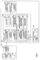
- FIG. 1 is a block diagram of an image processing system according to one embodiment of the present invention.
- a host personal computer as an example of an information processing apparatus
- MFP multi-function peripheral machine
- the host PC 100 has a structure comprising a display part 101, a driver 102, a user interface (UI) 103 and a communication part 104.
- the MFP 200 has a structure comprising a control part 210, a control panel 250, a read part 260 and a print part 270.
- the control part 210 has a structure comprising a host PC communication part 211, an image retain part 212, a format conversion part 213, a read part I/F 214, a print part I/F 215, an engine information retain part 216, a preview image creation part 217, and a panel I/F 218.
- the preview image creation part 217 has a structure comprising a preview original-image creation part 221, a preview parts-image creation part 222, a preview image synthesis part 223 and a preview image retain part 224.
- the control panel 250 comprises a display part 251 and a UI 252. Moreover, the print part 270 comprises staple information 271. It should be noted that processes of each part shown in FIG. 1 will be mentioned later.
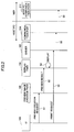
- FIG. 2 is a sequence chart showing a process procedure of an image processing system.
- the UI 103 of the host PC 100 sends, in step S1, a preview creation request to the preview image creation part 105.
- the preview image creation part 105 creates a preview image from print data.
- the process proceeds to step S2 where the preview image creation part 105 sends a preview image to a display part 101 as a preview result.
- step S3 the display part 101 displays the preview image.
- the operator checks the preview image displayed on the display part 101, and, if there is no problem, makes a print request through the UI 103.
- step S4 the UI 103 sends the print request to the driver 102.
- the driver 102 can send, in steps S5 and S6, the print request to the host PC communication part 211 of the MFP 200 through the communication part 104.
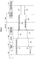
- FIG. 3 is a sequence chart showing a process procedure of the image processing system according to the present invention.
- a preview image of print data is displayed on the display part 101.
- the UI 103 of the host PC 100 sends, in step S11, a preview creation request to the driver 102. Then, the process proceeds to steps S12, S13 and S14 where the driver 102 sends the preview creation request to the preview image creation part 217 through the host PC communication part 211 of the MFP 200.
- the preview image creation part 217 creates a preview image from the print data. Then, in steps S15, S16, S17 and S18, the preview picture creation part 217 sends the preview image as a preview result to the display part through the host PC communication part 211, the communication part 104 and the driver 102 of the host PC 100. Then, the process proceeds to step S19 where the display part 101 displays the preview image. The operator can check the preview image displayed on the display part 101.
- the preview image accurately expressing the output result of the MFP 200 can be created since the preview image is created on the side of the MFP 200.
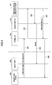
- FIG. 4 is a sequence chart of another example of process procedure of the image processing system according to the present invention. According to the sequence chart of FIG. 4, a preview image of read data acquired by reading by the read part 260 is displayed on the operation panel 250.
- the operation panel 250 of the MFP 200 sends, in step steps S21 and S22, a preview creation request to the preview image creation part 217 through the panel I/F 218.
- the preview image creation part 217 sends, in steps S23 and S24, a read request to the reading part 260 through the read part I/F 214. Then, the process proceeds to step S25 where the preview image creation part 217 creates a preview image from the read data. Then, the process proceeds to step S25 and S26 where the preview image creation part 217 sends the preview image as a preview result to the operation panel 250 through the panel I/F 218.
- the display part 251 of the operation panel 250 displays the preview image. The operator can check the preview image displayed on the display part 251 of the operation panel 250.
- the preview image accurately expressing the output result of the MFP 200 can be created even if the preview image corresponds to the read data acquired by the read part 260 since the preview image is created on the side of the MFP 200.
- the image processing system since the image processing system according to the present invention creates a preview image by the preview image creation part 217 of the MFP 200, creation of the preview picture can be unified.
- FIG. 5 is a sequence chart of a process performed in an image processing system different from the image processing system according to the present invention.
- the host PC 100 receives, in step S31, a preview image display request from an operator. Then, the host PC 100 creates, in step S32, a preview image 500 from, for example, print data. Then, the host PC 100 displays the preview image 500.
- the operator checks the displayed preview image 500. If there is no problem in the preview image 500, the operator sends, in step S33, a print request. Then, the host PC 100 sends, in step S34, the print request to the MFP 200.
- the MFP 200 carries out printing based on the print request from the host PC 100, and outputs printed matters 510 as an output result.
- the printed matters 510 are bound by two a staple 511 at two positions.
- the staples 511 of the printed matter 510 at two positions are not expressed in the preview image 500, and it cannot be determined from the preview image 500 whether or not the staples 511 overlap the characters printed on the printed matters. Additionally, a relationship between the orientation of the printed matter 510 and the staples 511 in the image processing system shown in FIG. 5. It should be noted that the above-mentioned problem due to difference between the preview image 500 and the printed matter 510 may occur when punching is applied to the printed mattes 510.
- FIG. 6 is a sequence chart of a process performed by the image processing system according to the present invention.
- step S41 the host PC 100 receives a preview image display request from an operator. Then, in step S42, the host PC 100 sends a preview creation request to the MFP 200. Then, the process proceeds to step S43 where the MFP 200 creates a preview image 600 from print data.
- the preview image 600 expresses that the printed matters are bound by staples 601 at two positions.
- step S44 the MFP 200 sends the preview image as a preview result to the host PC 100.
- the host PC 100 displays the preview image 610.
- the preview image 610 is identical to the preview image 600, and expresses that the printed matte is bound byte staples 611 at two positions.
- step S45 the operator checks the displayed preview image 610. If there is no problem in the preview image 610, the operator makes, in step S45, a print request. Then, the process proceeds to step S46 where the host PC 100 sends the print request to the MFP 200.
- the MFP 200 carries out printing based on the print request from the host PC 100, and outputs the printed matter 620 as an output result.
- the printed matter 620 is bound by the staples 621 at two positions.
- two staples 621 of the printed matter 620 are expressed as the staples 601 in the preview image 600 in the image processing system according to the present invention, it can be determined from the preview image 600 whether or not the staples 601 overlap characters. Additionally, in the image processing system according to the present invention, a relationship between the orientation of the printed matter 620 and the staples 621 can be checked.
- a relationship between an orientation of the output result and the staple positions or punch positions or whether or not the staples or punch holes overlap characters can be checked before printing since the finished image considering not only the output result according to the printing function but also the finish according to functions other than the printing function (for example, a stapling function or a punching function).
- FIG. 7 is a sequence chart of a process performed by an image processing system different from the image processing system according to the present invention.
- the host PC 100 receives the preview image display request from an operator.
- the host PC 100 creates a preview image 700 from print data. Then, the host PC 100 displays the preview image 700.
- the operator checks the displayed preview image 700.
- the output result based on the print data can be checked by the preview image 700, an intensive output result cannot be checked.
- an example will be described in which the operator desires an output of printed matter 720.
- step S53 If there is no problem in the range which can be checked by the preview image 700, the operator makes, in step S53, an intensive print request.
- step S54 the host PC 100 sends the intensive print request to_the MFP 200.
- the MFP 200 carries out printing based on the intensive print request from the host PC 100, and outputs printed matter 710 as an output result.
- the printed matter 710 differs from the printed matter 720 which the operator desires to have.
- the appearance of the printed matter 710 as a result of the intensive output is not expressed in the preview image 700, and it cannot determined a failure in the intensive printing from the preview image 700. Additionally, in the image processing system performing the process shown in FIG. 7, it is difficult to check a finish of staples or punch holes from the preview image 700.
- FIG. 8 is a sequence chart of a process performed in the image processing system according to the present invention.
- a host PC 100 receives a preview image display request from an operator.
- the host PC 100 sends a preview creation request to the MFP 200.
- the process proceeds to step S63 where the MFP 200 creates a preview image 800 from print data.
- the preview image 800 expresses the appearance of the intensive output result.
- the preview image 800 accurately expressing the appearance of the intensive output result can be created since the preview image 800 is created by the MFP 200.
- step S64 the MFP 200 sends the preview image 800 to the host PC 100 as a preview result.
- the' host PC 100 displays the preview image 810.
- the preview image 810 is identical to the preview image 800, and expresses the appearance of the intensive output result.
- the operator checks the preview image 810 which shows the appearance of the intensive output result so as to determine a failure occurring in the intensive printing easily.
- the determination of occurrence of a failure in the intensive printing due to, for example, a setting error can be made since an appearance of the intensive output result is expressed in the preview image 810.
- a failure in the intensive printing due to a setting error can be checked before printing since the intensive output result of the intensive printing in which an image processing is performed in the MFP 200 can be displayed as the preview image 810.
- FIG. 9 is a sequence chart of a process performed in the image processing system according to the present invention.
- step S71 the host PC 100 receives a preview image display request from the operator.
- step S72 the host PC 100 sends a preview creation request to the MFP 200.
- step S73 the MFP 200 creates a preview image 902 by synthesizing an image 900 according to the print data and a format 900 for synthesis stored in the MFP 200.
- a preview image 902 which is a result of synthesis of the image 900 according to the print data and the format 901 for synthesis stored in the MFP 200, can be created since the preview image 902 is created by the MFP 200.
- step S74 the MFP 200 sends the preview image 902 to the host PC 100 as a preview result.
- the host PC 100 displays a preview image 910.
- the preview image 910 is identical to the preview image 902, and expresses an appearance of the output result in which the image 900 according to the print data and the format 901 for synthesis stored in the MFP 200 are synthesized.
- the appearance of the output result in which the image 900 according to the print data and the format 901 for synthesis stored in the MFP 200 are synthesized can be checked since the appearance of the output result in which the image 900 according to the print data and the format 901 for synthesis stored in the MFP 200 are synthesized is expressed in the preview image 910.
- the output result of the synthesis printing can be checked before printing since the output result according to the synthesis printing in which an image processing is performed in the MFP 200 can be displayed as the preview image 910.
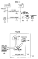
- FIG. 10 is an illustration for explaining a feature of the image processing system according to the present invention which unifies creation of a preview image.
- the preview image creation part 217 is provided to the control part 210 of the MFP 200.
- the same preview image can be achieved irrespective of the input means such as the host PC or the read part 260 by unifying the preview image creation part 217.
- the FP 200 according to the present invention can display the preview image, which is created in accordance with the preview creation request from the host PC 100, on the operation panel 250 of its own.
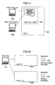
- FIG. 11 is an illustration for explaining a feature of the image processing system according to the present invention which unifies creation of a preview image.
- the preview image creation part 217 is provided to the control part 210 of the MFP 200.
- a difference between operating systems of a host PCs 100a and 100b can be absorbed by unifying the preview image creation part 217.
- a difference between the host PCs 100a and 100b can be eliminated by unifying the preview image creation part 217 so as to achieve the same preview image.
- FIG. 12 is an illustration for explaining a feature of the image processing system according to the present invention, which unifies creation of a preview image for each MFP.
- a difference peculiar to equipments between MFPs 200a and 200b is absorbed by unifying creation of a preview image for each of the MFPs 200a and 200b.
- the MFP 200a creates a preview image 1200 in which a staple extends in a slanting direction.
- the MFP 200b creates a preview image in which a staple extends in a vertical direction. Accordingly, in the image processing system according to the present invention, a preview image corresponding to the difference peculiar to each equipment of the MFPs 200a and 200b can be achieved by unifying creation of the preview image for each MFP.
- FIG. 13 A description will now be given, with reference to FIG. 13, of a feature of the image processing system according to the present invention, which creates a finished image considering not only an output result according to a printing function but also a finish according to a function other than a printing function
- FIG. 13 is an illustration for explaining a feature of the image processing system according to the present invention, which crates a finished image considering not only an output result according to a printing function but also a function other than the printing function, as a preview image.
- Print data or read data from the host PC 100, the read part 260, another host PC 100a connected via the network 300, and the MFP 200a are supplied to the format conversion part 213, and is converted into a unified format. Then, a preview original-image creation part 221 creates an original image for preview from the print data or the read data, which has been converted into a unified format.
- the preview parts-image creation part 222 acquires equipment information such as, for example, staple information 271 of the print part 270 so as to create a parts image for review.
- equipment information such as, for example, staple information 271 of the print part 270 so as to create a parts image for review.
- the parts-image for preview is an image expressed as a finished image corresponding to a staple, a punch hole, a format of synthesis, a stamp, etc.
- the preview image synthesis part 223 creates a preview image 1300 by synthesizing the original image for preview created by the preview original-image creation part 221 and a parts image for preview created by the preview parts-image creation part 222.
- the same preview image 1300 can be displayed on any of the host PC 100, the operation panel 250, the host PC 100b connected via the network 300 and the MFP 200b by unitarily performing creation of the preview image 1300 by the MFP 200.
- a preview image in which a part peculiar to each equipment (for example, an orientation of a staple) is expressed accurately, can be created by unitarily performing creation of the preview image 1300 by the MFP 200.
- FIG. 14 is a flowchart of a process based on the preview image display request from the host PC.
- the preview image creation part 217 determined whether a preview image display request has been sent from the host PC 100. If there is the preview image display request sent from the host PC 100, the process proceeds to step S101 where the preview image creation part 217 converts print data or read data corresponding to the preview display request into unified format data by using the format conversion part 213.
- the preview original-image creation part 221 creates an original image for preview from the printed data or the read data, which has been converted into the unified format data.
- step S102 the preview parts-image creation part 222 acquires staple information 271 from, for example, the print part 270.
- the preview parts-image creation part 222 creates a parts-image for preview from the acquired staple information.
- step S104 the preview image synthesis part 223 determines an orientation of the original image for preview and a position of the parts-image for preview. Then, the process proceeds to step S105 where the preview image synthesis part 223 creates a preview image by synthesizing the original image for preview and the parts-image for preview.
- step S106 the preview image synthesis part 223 saves the preview image in the preview image retain part 224.
- step S107 the preview image creation part 217 sends the preview image saved in the preview image retain part 224 to the host PC 100, and the process proceeds to step S108. Additionally, if there is no preview image display request from the host PC 100 in step S100, the process proceeds to step S108.
- step S108 the control part 210 judges existence of the print request from the host PC 100. If there is no print request, the control part 210 continues the return process to the process of step S100. If there is the print request, the control part 210 performs the printing process of step S109. After the process of step S109 is completed, the process returns to step S100.
- the process based on the print request is performed upon checking whether or not a relationship between a staple position and a direction of an output result or whether or not a staple overlaps characters since the finished image can be displayed as the preview image.
- FIG. 15 is a flowchart of a process based on a print request from the operation panel of its own.
- the preview image creation part 217 determined whether or not there has been a print request sent from the operation panel of its own. If there is the print request from the operation panel 250, the process proceeds to step S121 where the preview image creation part 217 determines whether or not it is set to perform a preview.
- step S122 the preview image creation part 217 converts print data or read data corresponding to the preview image display request into unified format data by using the format conversion part 213. Additionally, the preview original-image creation part 221 creates an original image for preview from the print data or the read data, which has been converted into the unified format data.
- step S123 the preview parts-image creation part 222 acquires staple information 271 from, for example, the print part 270.
- the preview parts-image creation part 222 creates a parts-image for preview from the acquired staple information.
- step S125 the preview image synthesis part 223 determines an orientation of the original image for preview and a position of the parts-image for preview. Then, the process proceeds to step S126 where the preview image synthesis part 223 creates a preview image by synthesizing the original image for preview and the parts-image for preview. Then, the process proceeds to step S127 where the preview image synthesis part 223 saves the preview image in the preview image retain part 224.
- step S1208 the control part 210 displays the preview image, which is saved in the preview image retain part 224, on the operation panel. If there is no problem in the preview image, the operator inputs "check OK" through, for example, the operation panel 250. If the "check OK" is input through the operation panel 250, the control part 210 performs the print process of step S130. Additionally, if it is set to not perform a preview in step S121, the control part 210 performs the print process of step S130. It should be noted that the process returns to step S120 after the process of steps S130 and S131 is completed.
- step S120 the process returns to step S120 if there is no print request from the operation panel 250 in step S120.
- FIG. 16 is an illustration of an example of the preview image according to the present invention.
- the preview image 1600 shown in FIG. 16 is created by synthesizing an original image 1601 of intensive printing for preview, a parts image 1602 for preview of a staple, and a parts image 1603 for preview of a stamp.
- the preview image 1600 expresses not only an output result according to a printing function but also a finished image considering finish according to a function other than the printing function.
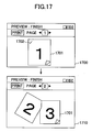
- FIG. 17 is an illustration of another example of the preview image according to the present invention.
- the preview image 1700 shown in FIG. 17 is created by synthesizing an original image 1701 for preview of both-sides printing and a parts image 1702 for preview of a staple.
- the host PC 100 displays a preview image 1710 on the display part 101.
- the preview images 1700 ad 1710 express not only an output result according to a printing function but also a finished image considering finish according to a function other than the printing function.
- the relationship between the output result and the staple position can be adjusted as follows.
- FIG. 18 is an illustration showing a relationship between the output result and the staple position.
- a preview image 1800 of FIG. 18 is an example of failure in stapling because a staple 1801 is located at a position which the operator does not intend to.
- a preview image 1810 is an example of success in stapling because a staple 1811 is located at a position which the operator intends to.
- the failure in stapling in the preview image 1800 occurs due to incorrect determination of the direction of the output result.
- the preview image 1800 in which a failure occurs in stapling can be adjusted to the preview image 1810 in which stapling is succeeded.
- FIGS. 19A and 19B are illustrations showing orientations of an original document set in the ADF.
- FIG. 20 is an illustration of a screen for designating an orientation of an original document set in the ADF.
- the operator should press a button 2002 in the screen 2000 shown in FIG. 20.
- the operator should press a button 2001 in the screen 2000 shown in FIG. 20.
Landscapes
- Engineering & Computer Science (AREA)
- Multimedia (AREA)
- Signal Processing (AREA)
- Human Computer Interaction (AREA)
- Record Information Processing For Printing (AREA)
- Facsimiles In General (AREA)
- Control Or Security For Electrophotography (AREA)
- Image Processing (AREA)
Abstract
Description
- The present invention generally relates to image processing techniques and, more particularly, to an information processing apparatus such as an image processing apparatus, an image processing method and image processing system, which handle a preview screen image.
- In an image processing system in which a host personal computer (host PC) as an example of an information processing apparatus and a multi-function peripheral machine (MFP) as an example of an image processing apparatus are communicably connected with each other, there is a system having a preview function to check an output result according to a preview image displayed on a screen of the host PC before sending a print request from the host PC to the MFP.
- Usually, such a preview function is provided in software of the host PC. Thus, according to the conventional preview function, an actual output result may differ slightly from the preview image. Specifically, there is a case in which an actual output result differs slightly from a preview image due to differences in resolution and color between the MFP and the host PC.
-
Patent Document 1 discloses prevention of an actual output result from differing slightly from a preview image by causing a host PC to display a preview image which is created on a printer side in consideration of a printing function. - Patent Document 1:
Japanese Laid-Open Patent Application No. 2003-76512 - Among recent MFPs, there is one provided with a stapling function for stapling a printed matter or a punching function for punching a printed matter besides a printing function. Such an MFP can check an output result according to a preview image but it is difficult to check a relationship between the output result and a stapling position or punching position.
- Accordingly, in a conventional MFP, there is a problem that a relationship between an output result and a stapling position or a punching position is different from what an operator intends to even if printing is performed after the operator checked the output result according to a preview image, or there is a problem in that a staple or a punched hole is not prevented from overlapping an image such as characters on a printed matter.
- It is a general object of the present invention to provide an image processing technique in which the above-mentioned problems are eliminated.
- A more specific object of the present invention is to provide an image processing apparatus, an information processing apparatus, an image processing method and an image processing system, which is capable of displaying a preview image accurately expressing a finished image of a printed matter.
- In order to achieve the above-mentioned objects, there is provided according to one aspect of the present invention an image processing apparatus having a printing function, comprising: a preview original-image creation part that creates an original image for preview based on print data; a preview parts image creation part that creates a parts image for preview peculiar to each equipment; a preview image synthesis part that synthesizes a preview image from the original image for preview and the parts image for preview; and a preview image retaining part that retains the preview image.
- In the image processing apparatus according to the present invention, the preview parts-image creation part may create an image of a part formed by a function other than the printing function so as to be the parts image for preview peculiar to each equipment. The preview parts-image creation part may create an image peculiar to each equipment formed by the printing function so as to be the parts image for preview peculiar to each equipment.
- The image processing apparatus according to the present invention may further comprise a format conversion part that converts a format of the print data supplied from different supply sources into a unified format.
- The preview parts-image creation part may render an image of a part where stapling or punching is applied to be a part formed by a function other than the printing function. The preview parts-image creation part may creates an image of a format or a stamp for synthesis so as to be the image peculiar to each equipment formed by the printing function.
- In the image processing apparatus according to the present invention, the preview image retained by the preview image retaining part may be displayed on a display part of the image processing apparatus or an information processing apparatus communicable with the image processing apparatus.
- There is provided according to another aspect of the present invention an image processing method of an image processing apparatus having a printing function, comprising: a step of creating an original image for preview based on print data; a step of creating a parts image for preview peculiar to each equipment; a step of synthesizing a preview image from the original image for preview and the parts image for preview; and a step of retaining the preview image.
- In the image processing method according to the present invention, the step of creating a parts image for preview peculiar to each equipment may create an image of a part formed by a function other than the printing function so as to be the parts image for preview peculiar to each equipment. The step of creating a parts image for preview peculiar to each equipment may create an image peculiar to each equipment formed by the printing function so as to be the parts image for preview peculiar to each equipment.
- The image processing method according to the present invention may further comprise a step of converting a format of the print data supplied from different supply sources into a unified format. The step of creating a parts-image for preview peculiar to each equipment may render an image of a part where stapling or punching is applied to be an image of a part formed by a function other than the printing function.
- In the image processing method according to the present invention, the step of creating a parts image for preview may create an image of a format or a stamp for synthesis so as to be the image peculiar to each equipment formed by the printing function.
- The image processing method according to the present invention may further comprise a step of causing a display part of the image processing apparatus or an information processing apparatus communicable with the image processing apparatus to display the preview image retained by the step of retaining the preview image.
- There is provided according to the present invention an image processing system comprising an image processing apparatus having a printing function and an information processing apparatus communicably connected with the image forming apparatus and making various requests to the image processing apparatus, wherein the image processing apparatus includes: a preview original-image creation part that creates an original image for preview based on print data; a preview parts-image creation part that creates a parts image for preview peculiar to each equipment; a preview image synthesis part that synthesizes a preview image from the original image for preview and the parts image for preview; and a preview image retaining part that retains the preview image, wherein the image processing apparatus includes a control part that requests the preview image of print data to the image processing apparatus and receives the preview image from the image processing apparatus so as to display the received preview image on a display part.
- In the image processing system according to the present invention, the preview parts-image creation part may create an image of a part formed by a function other than the printing function so as to be the parts image for preview peculiar to each equipment. The preview parts-image creation part may create an image peculiar to each equipment formed by the printing function so as to be the parts image peculiar for preview to each equipment. The image processing system according to the present invention may further comprise a format converting part that converts a format of the print data supplied from different supply sources into a unified format. The preview parts-image creation part may render an image of a part where stapling or punching is applied to be a part formed by a function other than the printing function. The preview parts-image creation part may create an image of a format or a stamp for synthesis so as to be the image peculiar to each equipment formed by the printing function.
- According to the present invention, an image processing apparatus, an information processing apparatus, an image processing method and an image processing system, which is capable of displaying a preview image accurately expressing a finish of a printed matter, can be provided.
- Other objects, features and advantages of the present invention will become more apparent from the following detailed description when read in conjunction with the accompanying drawings.
-
- FIG. 1 is a block diagram of an image processing system according to an embodiment of the present invention;
- FIG. 2 is a sequence chart of a process procedure of an image processing system different from the image process system according to the present invention;
- FIG. 3 is a sequence chart of a process procedure of the image processing system according to the present invention;
- FIG. 4 is a sequence chart of another process procedure of the image processing system according to the present invention;
- FIG. 5 is a sequence chart of a process by an image processing system different from the image processing system according to the present invention;
- FIG. 6 is a sequence chart of a process by the image processing system according to the present invention;
- FIG. 7 is a sequence chart of a process by an image processing system different form the image processing system according to the present invention;
- FIG. 8 is a sequence chart of a process by the image processing system according to the present invention;
- FIG. 9 is a sequence chart of a process by the image processing system according to the present invention;
- FIG. 10 is an illustration for explaining an example expressing a feature of the image processing system according to the present invention which unifies creation of preview images;
- FIG. 11 is an illustration for explaining another example expressing a feature of the image processing system according to the present invention which unifies creation of preview images;
- FIG. 12 is an illustration for explaining an example expressing a feature of the image processing system according to the present invention which unifies creation of preview images on an individual MFP basis;
- FIG. 13 is an illustration for explaining an example expressing a feature of the image processing system according to the present invention which creates a finished image as a preview image considering not only an output result by a printing function but also a finish according to a function other than a printing function;
- FIG. 14 is a flowchart of a process based on a preview image display request from a host PC;
- FIG. 15 is a flowchart of a process based on a print request from an operation panel;
- FIG. 16 is an illustration of a preview image according to the present invention;
- FIG. 17 is an illustration of another preview image according to the present invention;
- FIG. 18 is an illustration showing a relationship between a staple position and a direction of an output result of a preview image;
- FIGS. 19A and 19B are illustrations showing orientations of an original document set in an ADF; and
- FIG. 20 is an illustration of a screen for designating an orientation of an original document set in an ADF.
- A description will now be given, with reference to the drawings, of embodiments according to the present invention.
- FIG. 1 is a block diagram of an image processing system according to one embodiment of the present invention. In the image processing system shown in FIG. 1, a host personal computer (host PC) as an example of an information processing apparatus and a multi-function peripheral machine (MFP) 200 as an example of an image processing apparatus are communicably connected with each other.
- The
host PC 100 has a structure comprising adisplay part 101, adriver 102, a user interface (UI) 103 and acommunication part 104. TheMFP 200 has a structure comprising acontrol part 210, acontrol panel 250, aread part 260 and aprint part 270. - The
control part 210 has a structure comprising a hostPC communication part 211, animage retain part 212, aformat conversion part 213, a read part I/F 214, a print part I/F 215, an engine information retainpart 216, a previewimage creation part 217, and a panel I/F 218. - The preview
image creation part 217 has a structure comprising a preview original-image creation part 221, a preview parts-image creation part 222, a previewimage synthesis part 223 and a preview image retainpart 224. - The
control panel 250 comprises adisplay part 251 and aUI 252. Moreover, theprint part 270 comprisesstaple information 271. It should be noted that processes of each part shown in FIG. 1 will be mentioned later. - For the sake of easy understanding of the present invention, a description will be given below, with reference to FIG. 2, of a process of printing according to a request by an operator after displaying a preview image in a conventional image processing system. FIG. 2 is a sequence chart showing a process procedure of an image processing system.
- For example, when a preview image display request is made by an operator, the
UI 103 of thehost PC 100 sends, in step S1, a preview creation request to the previewimage creation part 105. The previewimage creation part 105 creates a preview image from print data. Then, the process proceeds to step S2 where the previewimage creation part 105 sends a preview image to adisplay part 101 as a preview result. - Then, the process proceeds to step S3 where the
display part 101 displays the preview image. The operator checks the preview image displayed on thedisplay part 101, and, if there is no problem, makes a print request through theUI 103. Then, the process proceeds to step S4 where theUI 103 sends the print request to thedriver 102. Thus, thedriver 102 can send, in steps S5 and S6, the print request to the hostPC communication part 211 of theMFP 200 through thecommunication part 104. - Thus, in the sequence chart shown in FIG. 2, there may be a case where the output result of the
MFP 200 slightly differs from the preview image since the preview image is created on the side of thehost PC 100. - A description will be now be given, with reference to FIG. 3, of a process of displaying a preview image in the image processing system according to the present invention. FIG. 3 is a sequence chart showing a process procedure of the image processing system according to the present invention. In the sequence chart shown in FIG. 3, a preview image of print data is displayed on the
display part 101. - When the a preview image display request is made by an operator, the
UI 103 of thehost PC 100 sends, in step S11, a preview creation request to thedriver 102. Then, the process proceeds to steps S12, S13 and S14 where thedriver 102 sends the preview creation request to the previewimage creation part 217 through the hostPC communication part 211 of theMFP 200. - The preview
image creation part 217 creates a preview image from the print data. Then, in steps S15, S16, S17 and S18, the previewpicture creation part 217 sends the preview image as a preview result to the display part through the hostPC communication part 211, thecommunication part 104 and thedriver 102 of thehost PC 100. Then, the process proceeds to step S19 where thedisplay part 101 displays the preview image. The operator can check the preview image displayed on thedisplay part 101. - Thus, according to the sequence chart shown in FIG. 3, the preview image accurately expressing the output result of the
MFP 200 can be created since the preview image is created on the side of theMFP 200. - A description will now be given, with reference to FIG. 4, of another process of displaying a preview image in the image processing system according to the present invention. FIG. 4 is a sequence chart of another example of process procedure of the image processing system according to the present invention. According to the sequence chart of FIG. 4, a preview image of read data acquired by reading by the
read part 260 is displayed on theoperation panel 250. - For example, when a preview image display request is made by an operator, the
operation panel 250 of theMFP 200 sends, in step steps S21 and S22, a preview creation request to the previewimage creation part 217 through the panel I/F 218. - The preview
image creation part 217 sends, in steps S23 and S24, a read request to thereading part 260 through the read part I/F 214. Then, the process proceeds to step S25 where the previewimage creation part 217 creates a preview image from the read data. Then, the process proceeds to step S25 and S26 where the previewimage creation part 217 sends the preview image as a preview result to theoperation panel 250 through the panel I/F 218. Thedisplay part 251 of theoperation panel 250 displays the preview image. The operator can check the preview image displayed on thedisplay part 251 of theoperation panel 250. - Thus, according to the sequence chart shown in FIG. 4, the preview image accurately expressing the output result of the
MFP 200 can be created even if the preview image corresponds to the read data acquired by theread part 260 since the preview image is created on the side of theMFP 200. - As indicated in the sequence chart shown in FIGS. 3 and 4, since the image processing system according to the present invention creates a preview image by the preview
image creation part 217 of theMFP 200, creation of the preview picture can be unified. - Furthermore, for the sake of easy understanding of the present invention, a description will be given below, with reference to FIG. 5, of a process of printing after a preview image is displayed in a different image processing system.
- FIG. 5 is a sequence chart of a process performed in an image processing system different from the image processing system according to the present invention. The
host PC 100 receives, in step S31, a preview image display request from an operator. Then, thehost PC 100 creates, in step S32, apreview image 500 from, for example, print data. Then, thehost PC 100 displays thepreview image 500. - The operator checks the displayed
preview image 500. If there is no problem in thepreview image 500, the operator sends, in step S33, a print request. Then, thehost PC 100 sends, in step S34, the print request to theMFP 200. - The
MFP 200 carries out printing based on the print request from thehost PC 100, and outputs printedmatters 510 as an output result. The printed matters 510 are bound by two astaple 511 at two positions. - Thus, in the image processing system performing the process shown in FIG. 5, the
staples 511 of the printedmatter 510 at two positions are not expressed in thepreview image 500, and it cannot be determined from thepreview image 500 whether or not thestaples 511 overlap the characters printed on the printed matters. Additionally, a relationship between the orientation of the printedmatter 510 and thestaples 511 in the image processing system shown in FIG. 5. It should be noted that the above-mentioned problem due to difference between thepreview image 500 and the printedmatter 510 may occur when punching is applied to the printed mattes 510. - A description will be given below, with reference to FIG. 6, of a process of printing after a preview image is displayed in the image processing system according to the present invention. FIG. 6 is a sequence chart of a process performed by the image processing system according to the present invention.
- In step S41, the
host PC 100 receives a preview image display request from an operator. Then, in step S42, thehost PC 100 sends a preview creation request to theMFP 200. Then, the process proceeds to step S43 where theMFP 200 creates apreview image 600 from print data. Thepreview image 600 expresses that the printed matters are bound bystaples 601 at two positions. - Then, in step S44, the
MFP 200 sends the preview image as a preview result to thehost PC 100. Thehost PC 100 displays thepreview image 610. Thepreview image 610 is identical to thepreview image 600, and expresses that the printed matte is boundbyte staples 611 at two positions. - The operator checks the displayed
preview image 610. If there is no problem in thepreview image 610, the operator makes, in step S45, a print request. Then, the process proceeds to step S46 where thehost PC 100 sends the print request to theMFP 200. - The
MFP 200 carries out printing based on the print request from thehost PC 100, and outputs the printedmatter 620 as an output result. The printedmatter 620 is bound by thestaples 621 at two positions. - Thus, since two
staples 621 of the printedmatter 620 are expressed as thestaples 601 in thepreview image 600 in the image processing system according to the present invention, it can be determined from thepreview image 600 whether or not thestaples 601 overlap characters. Additionally, in the image processing system according to the present invention, a relationship between the orientation of the printedmatter 620 and thestaples 621 can be checked. - That is, in the image processing system according to the present invention, a relationship between an orientation of the output result and the staple positions or punch positions or whether or not the staples or punch holes overlap characters can be checked before printing since the finished image considering not only the output result according to the printing function but also the finish according to functions other than the printing function (for example, a stapling function or a punching function).
- Furthermore, for the sake of easy understanding of the present invention, a description will be given below, with reference to FIG. 7, of a process of intensive printing after a preview image is displayed in an image processing system different from the image processing system according to the present invention.
- FIG. 7 is a sequence chart of a process performed by an image processing system different from the image processing system according to the present invention. In step S51, the
host PC 100 receives the preview image display request from an operator. In step S52, thehost PC 100 creates apreview image 700 from print data. Then, thehost PC 100 displays thepreview image 700. - The operator checks the displayed
preview image 700. However, although the output result based on the print data can be checked by thepreview image 700, an intensive output result cannot be checked.
Here, an example will be described in which the operator desires an output of printedmatter 720. - If there is no problem in the range which can be checked by the
preview image 700, the operator makes, in step S53, an intensive print request. In step S54, thehost PC 100 sends the intensive printrequest to_the MFP 200. - The
MFP 200 carries out printing based on the intensive print request from thehost PC 100, and outputs printedmatter 710 as an output result. The printedmatter 710 differs from the printedmatter 720 which the operator desires to have. - Thus, in the image processing system performing the process shown in FIG. 7, the appearance of the printed
matter 710 as a result of the intensive output is not expressed in thepreview image 700, and it cannot determined a failure in the intensive printing from thepreview image 700. Additionally, in the image processing system performing the process shown in FIG. 7, it is difficult to check a finish of staples or punch holes from thepreview image 700. - A description will now be given, with reference to FIG. 8, of a process of intensive printing performed after a preview image is displayed in the image processing system according to the present invention. FIG. 8 is a sequence chart of a process performed in the image processing system according to the present invention.
- In step S61, a
host PC 100 receives a preview image display request from an operator. In step S62, thehost PC 100 sends a preview creation request to theMFP 200. Then, the process proceeds to step S63 where theMFP 200 creates apreview image 800 from print data. Thepreview image 800 expresses the appearance of the intensive output result. In the image processing system according to the present invention, thepreview image 800 accurately expressing the appearance of the intensive output result can be created since thepreview image 800 is created by theMFP 200. - Then, the process proceeds to step S64 where the
MFP 200 sends thepreview image 800 to thehost PC 100 as a preview result. Then, the'host PC 100 displays thepreview image 810. Thepreview image 810 is identical to thepreview image 800, and expresses the appearance of the intensive output result. - For example, when the operator desires an output of the printed
matter 720 shown in FIG. 7, the operator checks thepreview image 810 which shows the appearance of the intensive output result so as to determine a failure occurring in the intensive printing easily. Thus, in the image processing system according to the present invention, the determination of occurrence of a failure in the intensive printing due to, for example, a setting error can be made since an appearance of the intensive output result is expressed in thepreview image 810. - That is, in the image processing system according to the present invention, a failure in the intensive printing due to a setting error can be checked before printing since the intensive output result of the intensive printing in which an image processing is performed in the
MFP 200 can be displayed as thepreview image 810. - A description will be given below, with reference to FIG. 9, of a process of displaying a preview image which is formed by synthesizing print data and a format for synthesis retained by the
MFP 200 in the image processing system according to the present invention. FIG. 9 is a sequence chart of a process performed in the image processing system according to the present invention. - In step S71, the
host PC 100 receives a preview image display request from the operator. In step S72, thehost PC 100 sends a preview creation request to theMFP 200. Then, the process proceeds to step S73 where theMFP 200 creates apreview image 902 by synthesizing animage 900 according to the print data and aformat 900 for synthesis stored in theMFP 200. In the image processing system according to the present invention, apreview image 902, which is a result of synthesis of theimage 900 according to the print data and theformat 901 for synthesis stored in theMFP 200, can be created since thepreview image 902 is created by theMFP 200. - Then, the process proceeds to step S74 where the
MFP 200 sends thepreview image 902 to thehost PC 100 as a preview result. Thehost PC 100 displays apreview image 910. Thepreview image 910 is identical to thepreview image 902, and expresses an appearance of the output result in which theimage 900 according to the print data and theformat 901 for synthesis stored in theMFP 200 are synthesized. - Thus, in the image processing system according to the present invention, the appearance of the output result in which the
image 900 according to the print data and theformat 901 for synthesis stored in theMFP 200 are synthesized can be checked since the appearance of the output result in which theimage 900 according to the print data and theformat 901 for synthesis stored in theMFP 200 are synthesized is expressed in thepreview image 910. - That is, in the image processing system according to the present invention, the output result of the synthesis printing can be checked before printing since the output result according to the synthesis printing in which an image processing is performed in the
MFP 200 can be displayed as thepreview image 910. - A description will now be given, with reference to FIG. 10, of a feature of the image processing system of the present invention which unifies creation of preview images. FIG. 10 is an illustration for explaining a feature of the image processing system according to the present invention which unifies creation of a preview image.
- In the image processing system according to the present invention, the preview
image creation part 217 is provided to thecontrol part 210 of theMFP 200. Thus, in the image processing system according to the present invention, the same preview image can be achieved irrespective of the input means such as the host PC or theread part 260 by unifying the previewimage creation part 217. Additionally, theFP 200 according to the present invention can display the preview image, which is created in accordance with the preview creation request from thehost PC 100, on theoperation panel 250 of its own. - FIG. 11 is an illustration for explaining a feature of the image processing system according to the present invention which unifies creation of a preview image. In the image processing system according to the present invention, similar to FIG. 10, the preview
image creation part 217 is provided to thecontrol part 210 of theMFP 200. Thus, in the image processing system according to the present invention, a difference between operating systems of ahost PCs image creation part 217. - For example, as an example in which a difference exists in the operating system, there is a case where the
host PC 100a uses Windows (registered trademark) and thehost PC 100 uses MAC (registered trademark). Accordingly, in the image processing system according to the present invention, a difference between thehost PCs image creation part 217 so as to achieve the same preview image. - A description will now be given, with reference to FIG. 12, of a feature of the image processing system according to the present invention, which unifies creation of a preview image for each
MFP 200. FIG. 12 is an illustration for explaining a feature of the image processing system according to the present invention, which unifies creation of a preview image for each MFP. - In the image processing system according to the present invention, a difference peculiar to equipments between MFPs 200a and 200b, such as, for example, an orientation of a staple, is absorbed by unifying creation of a preview image for each of the MFPs 200a and 200b. For example, the
MFP 200a creates apreview image 1200 in which a staple extends in a slanting direction. On the other hand, theMFP 200b creates a preview image in which a staple extends in a vertical direction. Accordingly, in the image processing system according to the present invention, a preview image corresponding to the difference peculiar to each equipment of the MFPs 200a and 200b can be achieved by unifying creation of the preview image for each MFP. - A description will now be given, with reference to FIG. 13, of a feature of the image processing system according to the present invention, which creates a finished image considering not only an output result according to a printing function but also a finish according to a function other than a printing function
- FIG. 13 is an illustration for explaining a feature of the image processing system according to the present invention, which crates a finished image considering not only an output result according to a printing function but also a function other than the printing function, as a preview image.
- Print data or read data from the
host PC 100, theread part 260, anotherhost PC 100a connected via thenetwork 300, and theMFP 200a are supplied to theformat conversion part 213, and is converted into a unified format. Then, a preview original-image creation part 221 creates an original image for preview from the print data or the read data, which has been converted into a unified format. - Moreover, the preview parts-
image creation part 222 acquires equipment information such as, for example,staple information 271 of theprint part 270 so as to create a parts image for review. It should be noted that the parts-image for preview is an image expressed as a finished image corresponding to a staple, a punch hole, a format of synthesis, a stamp, etc. - The preview
image synthesis part 223 creates apreview image 1300 by synthesizing the original image for preview created by the preview original-image creation part 221 and a parts image for preview created by the preview parts-image creation part 222. - Thus, in the image processing system according to the present invention, the
same preview image 1300 can be displayed on any of thehost PC 100, theoperation panel 250, thehost PC 100b connected via thenetwork 300 and theMFP 200b by unitarily performing creation of thepreview image 1300 by theMFP 200. - Moreover, in the image processing system according to the present invention, a preview image in which a part peculiar to each equipment (for example, an orientation of a staple) is expressed accurately, can be created by unitarily performing creation of the
preview image 1300 by theMFP 200. - FIG. 14 is a flowchart of a process based on the preview image display request from the host PC. In step S100, the preview
image creation part 217 determined whether a preview image display request has been sent from thehost PC 100. If there is the preview image display request sent from thehost PC 100, the process proceeds to step S101 where the previewimage creation part 217 converts print data or read data corresponding to the preview display request into unified format data by using theformat conversion part 213. The preview original-image creation part 221 creates an original image for preview from the printed data or the read data, which has been converted into the unified format data. - Then, in step S102, the preview parts-
image creation part 222 acquiresstaple information 271 from, for example, theprint part 270. Then, in step S103, the preview parts-image creation part 222 creates a parts-image for preview from the acquired staple information. - Then, in step S104, the preview
image synthesis part 223 determines an orientation of the original image for preview and a position of the parts-image for preview. Then, the process proceeds to step S105 where the previewimage synthesis part 223 creates a preview image by synthesizing the original image for preview and the parts-image for preview. - Then, the process proceeds to step S106 where the preview
image synthesis part 223 saves the preview image in the preview image retainpart 224. Then, in step S107, the previewimage creation part 217 sends the preview image saved in the preview image retainpart 224 to thehost PC 100, and the process proceeds to step S108. Additionally, if there is no preview image display request from thehost PC 100 in step S100, the process proceeds to step S108. - In step S108, the
control part 210 judges existence of the print request from thehost PC 100. If there is no print request, thecontrol part 210 continues the return process to the process of step S100. If there is the print request, thecontrol part 210 performs the printing process of step S109. After the process of step S109 is completed, the process returns to step S100. - Therefore, in the image processing system according to the present invention, the process based on the print request is performed upon checking whether or not a relationship between a staple position and a direction of an output result or whether or not a staple overlaps characters since the finished image can be displayed as the preview image.
- FIG. 15 is a flowchart of a process based on a print request from the operation panel of its own. In step S120, the preview
image creation part 217 determined whether or not there has been a print request sent from the operation panel of its own. If there is the print request from theoperation panel 250, the process proceeds to step S121 where the previewimage creation part 217 determines whether or not it is set to perform a preview. - If it is set to perform a preview, the process proceeds to step S122 where the preview
image creation part 217 converts print data or read data corresponding to the preview image display request into unified format data by using theformat conversion part 213. Additionally, the preview original-image creation part 221 creates an original image for preview from the print data or the read data, which has been converted into the unified format data. - Then, in step S123, the preview parts-
image creation part 222 acquiresstaple information 271 from, for example, theprint part 270. Then, in step S124, the preview parts-image creation part 222 creates a parts-image for preview from the acquired staple information. - Then, in step S125, the preview
image synthesis part 223 determines an orientation of the original image for preview and a position of the parts-image for preview. Then, the process proceeds to step S126 where the previewimage synthesis part 223 creates a preview image by synthesizing the original image for preview and the parts-image for preview. Then, the process proceeds to step S127 where the previewimage synthesis part 223 saves the preview image in the preview image retainpart 224. - Then, in step S128, the
control part 210 displays the preview image, which is saved in the preview image retainpart 224, on the operation panel. If there is no problem in the preview image, the operator inputs "check OK" through, for example, theoperation panel 250. If the "check OK" is input through theoperation panel 250, thecontrol part 210 performs the print process of step S130. Additionally, if it is set to not perform a preview in step S121, thecontrol part 210 performs the print process of step S130. It should be noted that the process returns to step S120 after the process of steps S130 and S131 is completed. - On the other hand, if there is a problem in the preview image, the operator inputs "check NG" through, for example, the
operation panel 250. If the "check NG" is input through theoperation panel 250, the process proceeds to step S131 where thecontrol part 210 discards the image and the preview image corresponding to the print request. It should be noted that the process returns to step S120 if there is no print request from theoperation panel 250 in step S120. - FIG. 16 is an illustration of an example of the preview image according to the present invention. The
preview image 1600 shown in FIG. 16 is created by synthesizing anoriginal image 1601 of intensive printing for preview, aparts image 1602 for preview of a staple, and aparts image 1603 for preview of a stamp. Thepreview image 1600 expresses not only an output result according to a printing function but also a finished image considering finish according to a function other than the printing function. - FIG. 17 is an illustration of another example of the preview image according to the present invention. The
preview image 1700 shown in FIG. 17 is created by synthesizing anoriginal image 1701 for preview of both-sides printing and aparts image 1702 for preview of a staple. When a next page is designated in thepreview image 1700 of FIG. 17, thehost PC 100, for example, displays apreview image 1710 on thedisplay part 101. Thepreview images 1700ad 1710 express not only an output result according to a printing function but also a finished image considering finish according to a function other than the printing function. - In the image processing system according to the present invention, if a relationship between an output result and a position of the staple in the preview image is not what intended to, the relationship between the output result and the staple position can be adjusted as follows.
- FIG. 18 is an illustration showing a relationship between the output result and the staple position. A
preview image 1800 of FIG. 18 is an example of failure in stapling because astaple 1801 is located at a position which the operator does not intend to. Apreview image 1810 is an example of success in stapling because astaple 1811 is located at a position which the operator intends to. - The failure in stapling in the
preview image 1800 occurs due to incorrect determination of the direction of the output result. Thus, in theMFP 200 according to the present invention, by enabling a designation of an orientation of an original document set in an automatic document feeder (ADF), thepreview image 1800 in which a failure occurs in stapling can be adjusted to thepreview image 1810 in which stapling is succeeded. - FIGS. 19A and 19B are illustrations showing orientations of an original document set in the ADF. FIG. 20 is an illustration of a screen for designating an orientation of an original document set in the ADF. When an original document is set in the ADF as shown in FIG. 19A, the operator should press a
button 2002 in thescreen 2000 shown in FIG. 20. On the other hand, when an original document is set in the ADF as shown in FIG. 19B, the operator should press abutton 2001 in thescreen 2000 shown in FIG. 20. - The present invention is not limited to the specifically disclosed embodiments, and variations and modifications may be made without departing from the scope of the present invention.
Claims (20)
- An image processing apparatus having a printing function,
characterized by:a preview original-image creation part that creates an original image for preview based on print data,a preview parts image creation part that creates a parts image for preview peculiar to each equipment;a preview image synthesis part that synthesizes a preview image from said original-image for preview and said parts-image for preview; anda preview image retaining part that retains the preview image. - The image processing apparatus as claimed in claim 1, wherein said preview-parts image creation part creates an image of a part formed by a function other than said printing function so as to be the parts-image for preview peculiar to each equipment.
- The image processing apparatus as claimed in claim 1, wherein said preview parts-image creation part creates an image peculiar to each equipment formed by said printing function so as to be the parts image for preview peculiar to each equipment.
- The image processing apparatus as claimed in claim 1, further comprising a format conversion part that converts a format of the print data supplied from different supply sources into a unified format.
- The image processing apparatus as claimed in claim 2, wherein said preview parts-image creation part renders an image of a part where stapling or punching is applied to be a part formed by a function other than the printing function.
- The image processing apparatus as claimed in claim 3, wherein said preview parts-image creation part creates an image of a format or a stamp for synthesis so as to be the image peculiar to each equipment formed by the printing function.
- The image processing apparatus as claimed in claim 1 wherein the preview image retained by said preview image retain part is displayed on a display part of said image processing apparatus or an information processing apparatus communicable with said image processing apparatus.
- An image processing method of an image processing apparatus having a printing function, comprising:a step of creating an original image for preview based on print data;a step of creating a parts image for preview peculiar to each equipment;a step of synthesizing a preview image from the original image for preview and the parts image for preview; anda step of retaining the preview image.
- The image processing method as claimed in claim 8, wherein the step of creating a parts image for preview peculiar to each equipment creates an image of a part formed by a function other than the printing function so as to be the parts image for preview peculiar to each equipment.
- The image processing method as claimed in claim 8, wherein said step of creating a parts image for preview peculiar to each equipment creates an image peculiar to each equipment formed by said printing function so as to be the parts image for preview peculiar to each equipment.
- The image processing method as claimed in claim 8, further comprising a step of converting a format of the print data supplied from different supply sources into a unified format.
- The image processing method as claimed in claim 9, wherein said step of creating a parts image for preview peculiar to each equipment renders an image of a part where stapling or punching is applied to be an image of a part formed by a function other than the printing function.
- The image processing method as claimed in claim 9, wherein said step of creating a parts image for preview creates an image of a format or a stamp for synthesis so as to be the image peculiar to each equipment formed by the printing function.
- The image processing method as claimed in claim 8, further comprising a step of causing a display part of said image processing apparatus or an information processing apparatus communicable with said image processing apparatus to display the preview image retained by said step of retaining the preview image.
- An image processing system comprising an image processing apparatus having a printing function and an information processing apparatus communicably connected with said image forming apparatus and making various requests to said image processing apparatus,
characterized in that:said image processing apparatus includes:a preview original-image creation part that creates an original image for preview based on print data;a preview parts-image creation part that creates a parts image for preview peculiar to each equipment;a preview image synthesis part that synthesizes a preview image from said original image for preview and said parts image for preview; anda preview image retain part that retains the preview image,wherein said image processing apparatus includes a control part that requests the preview image of print data to said image processing apparatus and receives the preview image from said image processing apparatus so as to display the received preview image on a display part. - The image processing system as claimed in claim 15, wherein said preview parts-image creation part creates an image of a part formed by a function other than said printing function so as to be the parts image for preview peculiar to each equipment.
- The image processing system as claimed in claim 15, wherein said preview parts-image creation part creates an image peculiar to each equipment formed by said printing function so as to be the parts image for preview peculiar to each equipment.
- The image processing system as claimed in claim 16, further comprising a format converting part that converts a format of the print data supplied from different supply sources into a unified format.
- The image processing system as claimed in claim 16, wherein said preview parts-image creation part renders an image of a part where stapling or punching is applied to be a part formed by a function other than the printing function.
- The image processing system as claimed in claim 17, wherein said preview parts-image creation part creates an image of a format or a stamp for synthesis so as to be the image peculiar to each equipment formed by the printing function.
Applications Claiming Priority (1)
| Application Number | Priority Date | Filing Date | Title |
|---|---|---|---|
| JP2005303290A JP2007111906A (en) | 2005-10-18 | 2005-10-18 | Image processing apparatus, information processing apparatus, image processing method, and image processing system |
Publications (1)
| Publication Number | Publication Date |
|---|---|
| EP1777935A1 true EP1777935A1 (en) | 2007-04-25 |
Family
ID=37607251
Family Applications (1)
| Application Number | Title | Priority Date | Filing Date |
|---|---|---|---|
| EP06021695A Ceased EP1777935A1 (en) | 2005-10-18 | 2006-10-17 | Image processing apparatus, information processing apparatus, image processing method and image processing system |
Country Status (3)
| Country | Link |
|---|---|
| US (2) | US7826091B2 (en) |
| EP (1) | EP1777935A1 (en) |
| JP (1) | JP2007111906A (en) |
Families Citing this family (16)
| Publication number | Priority date | Publication date | Assignee | Title |
|---|---|---|---|---|
| JP2007188054A (en) * | 2005-12-15 | 2007-07-26 | Ricoh Co Ltd | Image forming apparatus, program, and item setting processing method |
| US8595623B2 (en) * | 2007-03-07 | 2013-11-26 | Ricoh Company, Ltd. | Image processing including process of outputting preview image using database storing synthesizing data corresponding to finish processing condition |
| JP2008287363A (en) * | 2007-05-15 | 2008-11-27 | Ricoh Co Ltd | Image processing apparatus, image processing method, and image processing program |
| JP4959435B2 (en) * | 2007-06-14 | 2012-06-20 | 株式会社リコー | Image processing apparatus, image forming apparatus, output format setting method, and output format setting program |
| JP4861255B2 (en) * | 2007-06-14 | 2012-01-25 | 株式会社リコー | Image forming apparatus, image forming method, and program |
| JP5060374B2 (en) * | 2008-04-15 | 2012-10-31 | キヤノン株式会社 | Information processing apparatus, information processing method, and program |
| JP5187007B2 (en) | 2008-06-05 | 2013-04-24 | 株式会社リコー | Image forming apparatus, display control method, and display control program |
| US20100091320A1 (en) * | 2008-10-14 | 2010-04-15 | Lena Sojian | Front Panel Display Recordation |
| JP5377044B2 (en) * | 2009-04-14 | 2013-12-25 | キヤノン株式会社 | Printing system, data processing method and program |
| JP5413154B2 (en) * | 2009-11-27 | 2014-02-12 | 株式会社リコー | Display device, image forming apparatus, customization method, program |
| US8984402B2 (en) * | 2010-12-20 | 2015-03-17 | Xerox Corporation | Visual indication of document size in a virtual rendering |
| JP2012203493A (en) * | 2011-03-24 | 2012-10-22 | Sharp Corp | Electronic device control system, electronic device, and electronic device control method |
| JP5962112B2 (en) * | 2012-03-23 | 2016-08-03 | 富士ゼロックス株式会社 | Display control apparatus, printing apparatus, and program |
| JP5994509B2 (en) * | 2012-09-18 | 2016-09-21 | 株式会社リコー | Image output system, portable terminal device, preview image creation control method, preview image creation control program, and image preview system |
| JP2020116822A (en) * | 2019-01-23 | 2020-08-06 | 株式会社リコー | Image forming apparatus, output state image forming method, and output state image forming program |
| JP7581775B2 (en) * | 2020-11-04 | 2024-11-13 | セイコーエプソン株式会社 | PROGRAM, DISPLAY METHOD, AND PRINT CONTROL DEVICE |
Citations (4)
| Publication number | Priority date | Publication date | Assignee | Title |
|---|---|---|---|---|
| US6115510A (en) | 1995-07-20 | 2000-09-05 | Canon Kabushiki Kaisha | Image processing apparatus capable of displaying image to be formed on sheet |
| US6285842B1 (en) | 1999-04-21 | 2001-09-04 | Sharp Kabishiki Kaisha | Apparatus for setting image forming conditions |
| US6473539B1 (en) | 1996-12-02 | 2002-10-29 | Canon Kabushiki Kaisha | Image processing apparatus with an image and binding positions display feature, related method, and medium |
| US6927865B1 (en) | 1999-06-23 | 2005-08-09 | Canon Kabushiki Kaisha | Information processing apparatus and method utilizing print previews, and computer-readable storage medium |
Family Cites Families (20)
| Publication number | Priority date | Publication date | Assignee | Title |
|---|---|---|---|---|
| JP3229382B2 (en) | 1992-01-28 | 2001-11-19 | 株式会社リコー | Color image forming equipment |
| JP3467138B2 (en) | 1995-03-07 | 2003-11-17 | 株式会社リコー | Image forming device |
| JPH10161480A (en) | 1996-12-02 | 1998-06-19 | Canon Inc | Image processing device |
| JPH10297057A (en) * | 1997-04-28 | 1998-11-10 | Canon Inc | Image processing apparatus and method, information processing apparatus and method, and storage medium |
| JP3563606B2 (en) | 1998-08-20 | 2004-09-08 | 富士ゼロックス株式会社 | Printing equipment |
| JP4240640B2 (en) * | 1999-03-05 | 2009-03-18 | キヤノン株式会社 | Image processing method, apparatus, and storage medium |
| JP2001051814A (en) * | 1999-08-16 | 2001-02-23 | Ricoh Co Ltd | Method of processing image data for preview of printer device |
| US6621590B1 (en) * | 1999-10-29 | 2003-09-16 | Hewlett-Packard Development Company, Lp. | Method and control for summarizing distribution of page-specific features within a multi-page print job |
| EP1191432A3 (en) | 2000-09-21 | 2004-09-29 | Ricoh Company, Ltd. | Virtual print previewing |
| US7102774B2 (en) * | 2000-11-30 | 2006-09-05 | Hewlett-Packard Development Company, L.P. | Print processing system and method |
| JP2003076512A (en) | 2001-08-31 | 2003-03-14 | Canon Inc | Information processing apparatus, printing apparatus, data processing method, storage medium, and program |
| JP2003320740A (en) | 2002-04-30 | 2003-11-11 | Canon Inc | Image processor |
| JP2004077616A (en) | 2002-08-12 | 2004-03-11 | Ricoh Co Ltd | Image forming device |
| US6911992B2 (en) * | 2002-10-18 | 2005-06-28 | Hewlett-Packard Development Company, L.P. | Poster preparation system and method |
| US7595903B2 (en) | 2003-01-23 | 2009-09-29 | Ricoh Company, Ltd. | Collaboration system, method and software program for image forming apparatuses |
| JP2005014328A (en) | 2003-06-25 | 2005-01-20 | Ricoh Co Ltd | Image forming apparatus |
| JP2005063243A (en) * | 2003-08-15 | 2005-03-10 | Ricoh Co Ltd | Information processing apparatus, program, and computer-readable recording medium |
| JP2005074712A (en) | 2003-08-29 | 2005-03-24 | Konica Minolta Business Technologies Inc | Image forming apparatus |
| US20070195335A1 (en) * | 2005-09-28 | 2007-08-23 | Kabushiki Kaisha Toshiba | Image forming apparatus |
| US7975224B2 (en) * | 2005-12-21 | 2011-07-05 | Xerox Corporation | WYSIWYG multifunction device finishing options |
-
2005
- 2005-10-18 JP JP2005303290A patent/JP2007111906A/en active Pending
-
2006
- 2006-10-13 US US11/580,164 patent/US7826091B2/en not_active Expired - Fee Related
- 2006-10-17 EP EP06021695A patent/EP1777935A1/en not_active Ceased
-
2010
- 2010-09-20 US US12/885,966 patent/US8120814B2/en not_active Expired - Fee Related
Patent Citations (4)
| Publication number | Priority date | Publication date | Assignee | Title |
|---|---|---|---|---|
| US6115510A (en) | 1995-07-20 | 2000-09-05 | Canon Kabushiki Kaisha | Image processing apparatus capable of displaying image to be formed on sheet |
| US6473539B1 (en) | 1996-12-02 | 2002-10-29 | Canon Kabushiki Kaisha | Image processing apparatus with an image and binding positions display feature, related method, and medium |
| US6285842B1 (en) | 1999-04-21 | 2001-09-04 | Sharp Kabishiki Kaisha | Apparatus for setting image forming conditions |
| US6927865B1 (en) | 1999-06-23 | 2005-08-09 | Canon Kabushiki Kaisha | Information processing apparatus and method utilizing print previews, and computer-readable storage medium |
Also Published As
| Publication number | Publication date |
|---|---|
| US20110007373A1 (en) | 2011-01-13 |
| US7826091B2 (en) | 2010-11-02 |
| US8120814B2 (en) | 2012-02-21 |
| JP2007111906A (en) | 2007-05-10 |
| US20070086073A1 (en) | 2007-04-19 |
Similar Documents
| Publication | Publication Date | Title |
|---|---|---|
| US8120814B2 (en) | Image processing apparatus, information processing apparatus, image processing method and image processing system | |
| US8040579B2 (en) | Image processing apparatus, computer program product, and preview image displaying method | |
| US6609162B1 (en) | Data processing apparatus connected to a network connectable a plurality of devices | |
| US7184169B2 (en) | Interleaved document rendering | |
| US5638186A (en) | Multi-function machine for combining and routing image data | |
| CN102447806B (en) | Printing system, computer, image forming apparatus and printing method | |
| US20130019160A1 (en) | Application cooperation system including server and image processing apparatus, and application cooperation method | |
| KR100914698B1 (en) | Printing system and host apparatus | |
| JP2011042176A (en) | Printer | |
| JP2004227136A (en) | Printer | |
| US20060119872A1 (en) | Printing processing system | |
| US20030020973A1 (en) | Color correction instruction apparatus | |
| JP2005197876A (en) | Image forming system | |
| US8705103B2 (en) | Image processing system, image processing server, image forming apparatus, image processing method, and recording medium | |
| US20030175061A1 (en) | Printer and print image reference system | |
| JP4079067B2 (en) | Mobile phone, printing apparatus, printing system and printing method therefor | |
| JP2008065534A (en) | Information processing system and server | |
| JP2009182914A (en) | Image forming apparatus | |
| JP4823341B2 (en) | Information processing system and server | |
| JP2009070302A (en) | Image processor, image processing method, and image processing program | |
| JP4992737B2 (en) | Image reading device | |
| JP2001138595A (en) | Printing system and printing device | |
| JP4661525B2 (en) | Image processing apparatus, image processing method, and image processing program | |
| JP2011022759A (en) | Image forming system and printing control device | |
| JP2006041963A (en) | Image forming apparatus |
Legal Events
| Date | Code | Title | Description |
|---|---|---|---|
| PUAI | Public reference made under article 153(3) epc to a published international application that has entered the european phase |
Free format text: ORIGINAL CODE: 0009012 |
|
| 17P | Request for examination filed |
Effective date: 20061017 |
|
| AK | Designated contracting states |
Kind code of ref document: A1 Designated state(s): AT BE BG CH CY CZ DE DK EE ES FI FR GB GR HU IE IS IT LI LT LU LV MC NL PL PT RO SE SI SK TR |
|
| AX | Request for extension of the european patent |
Extension state: AL BA HR MK YU |
|
| AKX | Designation fees paid |
Designated state(s): DE ES FR GB IT NL |
|
| 17Q | First examination report despatched |
Effective date: 20120703 |
|
| STAA | Information on the status of an ep patent application or granted ep patent |
Free format text: STATUS: THE APPLICATION HAS BEEN REFUSED |
|
| 18R | Application refused |
Effective date: 20131009 |