EP1777903A1 - Verfahren und Vorrichtung zur Übertragung von Energie und Daten zwischen einer Zentraleinheit und einem Knoten - Google Patents
Verfahren und Vorrichtung zur Übertragung von Energie und Daten zwischen einer Zentraleinheit und einem Knoten Download PDFInfo
- Publication number
- EP1777903A1 EP1777903A1 EP05109695A EP05109695A EP1777903A1 EP 1777903 A1 EP1777903 A1 EP 1777903A1 EP 05109695 A EP05109695 A EP 05109695A EP 05109695 A EP05109695 A EP 05109695A EP 1777903 A1 EP1777903 A1 EP 1777903A1
- Authority
- EP
- European Patent Office
- Prior art keywords
- voltage
- frt
- fit
- capacitor
- current sink
- Prior art date
- Legal status (The legal status is an assumption and is not a legal conclusion. Google has not performed a legal analysis and makes no representation as to the accuracy of the status listed.)
- Granted
Links
- 238000000034 method Methods 0.000 title claims abstract description 12
- 230000005540 biological transmission Effects 0.000 title claims description 8
- 239000003990 capacitor Substances 0.000 claims abstract description 19
- PCHJSUWPFVWCPO-UHFFFAOYSA-N gold Chemical compound [Au] PCHJSUWPFVWCPO-UHFFFAOYSA-N 0.000 claims abstract 2
- 239000010931 gold Substances 0.000 claims abstract 2
- 229910052737 gold Inorganic materials 0.000 claims abstract 2
- 230000001105 regulatory effect Effects 0.000 claims 2
- 230000006399 behavior Effects 0.000 description 3
- 230000008901 benefit Effects 0.000 description 3
- 230000001960 triggered effect Effects 0.000 description 2
- 238000001514 detection method Methods 0.000 description 1
- 238000011161 development Methods 0.000 description 1
- 230000018109 developmental process Effects 0.000 description 1
- 238000007599 discharging Methods 0.000 description 1
- 238000000605 extraction Methods 0.000 description 1
- 230000006870 function Effects 0.000 description 1
- 230000008520 organization Effects 0.000 description 1
- 230000008569 process Effects 0.000 description 1
- 230000004044 response Effects 0.000 description 1
- 230000011664 signaling Effects 0.000 description 1
Images


Classifications
-
- H—ELECTRICITY
- H04—ELECTRIC COMMUNICATION TECHNIQUE
- H04L—TRANSMISSION OF DIGITAL INFORMATION, e.g. TELEGRAPHIC COMMUNICATION
- H04L25/00—Baseband systems
- H04L25/02—Details ; arrangements for supplying electrical power along data transmission lines
Definitions
- the invention describes a method, a circuit arrangement and a system for exchanging data and for supplying power to at least one current sink connected to at least one data line pair with a fire alarm panel.
- Danger alarm systems such as fire, gas, temperature, etc. detection systems usually consist of detectors connected to a control center. Such alarm systems are used in public buildings, office buildings, hotels, industrial buildings, airports, railway stations, workshops, schools, etc. If an alarm is triggered on one of the detectors, the control panel will be notified. The functions of the control panel are freely parameterizable and support an alarm organization adapted to the object to be monitored. Such control panels usually have an integrated control panel with a graphical display and interfaces to communication networks. In these control panels or fire alarm control panels, fire detectors, display elements etc. are connected to the fire alarm panel via a data line pair, the so-called detector bus. There are so-called stitch and loop lines.
- the power supply of power sinks such as graphical controls on the individual floors of a building, surveillance cameras, graphic displays, control relays for example, the opening and closing of doors, windows, etc., which have a power consumption greater than 20 mA, via separate power lines.
- the current sinks For data transmission, the current sinks must then be connected again via data lines to the fire panel.
- the object of the invention is to be seen in the fact that the simplest and most efficient way to supply power to a power sink and to exchange data with a fire alarm panel via a data line pair will suggest.
- a core of the invention is to be seen in that for the exchange of data and for the power supply of at least one connected via at least one data line pair with a fire alarm center sink, which has a power consumption of more than 20mA, as a supply voltage for the on the at least one Data line pair connected current sink a pulsed voltage is used.
- a pulsed voltage For such a pulsed voltage either a clocked DC voltage or an AC voltage is used. Between two voltage pulses, useful data is transmitted to the fire panel.
- data can be payload and signaling data. The necessary voltage for the transmission of the data to the fire panel is provided by a previously charged by the supply voltage capacitor of a circuit arrangement in the current sink.
- the inventive circuit arrangement consists at least of a first DC / DC converter, a capacitor and a second DC / DC converter, which are connected in series behind one another.
- regulation of the current consumption from the detector bus is achieved by the first DC / DC converter.
- the first DC / DC converter limits the maximum permissible voltage at the capacitor during the charging process and at the same time limits the maximum current consumption on the two-wire line, with the help of the second DC / DC converter, the energy of the capacitor with maximum efficiency taken, ie the time of energy extraction is maximized.
- the capacitor is used as a power source for the transmission of useful data to the fire alarm panel between two voltage pulses when no power must be removed on the two-wire line.
- a so-called gold-cap capacitor is ideally integrated into the circuit arrangement.
- any current-storing element could be used which exhibits a short charging and discharging time.
- a big advantage is that current sinks, which have a high power consumption, are connected to the power supply and data exchange via the detector bus with the fire panel. This eliminates complex and separate cabling.
- Another advantage is that the existing in a building infrastructure for connecting such power sinks can be used and the power sinks behave as fire detectors, display elements, etc.
- FIG. 1 shows a fire control panel FS20 according to the invention with current sinks FRT / FIT connected via data lines. Both stitch and loop lines can be used.
- a current sink FRT / FIT is operated via the detector bus, the data line, therefore it must also behave like a fire detector. This means that the behavior at the initialization phase, e.g. for the detector bus, the address assignment as well as the redundancy behavior in the event of a fault must be identical to the fire detectors.
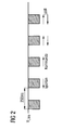
- Figure 2 shows a graphical example of a pulsed voltage.
- the detector bus communication is triggered every 250 ms in this example.
- a communication frame then takes about 125 ms.
- For the supply of the connected current sinks on the detector bus in this example about 60% of the duty cycle duration remains.
- no power must be drawn from the detector bus, as the current sinks communicate by means of a current response.
- the beginning of the communication phase is initiated by lowering the voltage to about 6V.
- the pulsed voltage may be either a clocked DC voltage or an AC voltage.
- FIG. 3 shows a simplified circuit arrangement SAO integrated in a current sink.
- a current sink FRT / FIT is operated via the detector bus, so it must also behave like a fire detector. This requires that a processor MSP must be used. On this processor MSP the fire alarm operating system is operated, which calls the terminal application.
- a stream sink FRT / FIT must be able to store many text messages and therefore needs a large memory. Since the MSP processor has at most a memory capacity of 60K FLASH or 10K RAM, a memory slot is provided for, for example, a MiniSDCard can be realized in a simple way a memory extension.
- the circuit arrangement SAO consists at least of a first DC / DC converter DC / DC, a capacitor K and a second DC / DC converter DC / DC, which are connected in series one behind the other. It ensures that the necessary voltage is made available for transferring data between two voltage pulses to the FS20 fire panel.
Landscapes
- Engineering & Computer Science (AREA)
- Power Engineering (AREA)
- Computer Networks & Wireless Communication (AREA)
- Signal Processing (AREA)
- Fire Alarms (AREA)
- Alarm Systems (AREA)
- Small-Scale Networks (AREA)
- Arrangements For Transmission Of Measured Signals (AREA)
- Selective Calling Equipment (AREA)
- Cable Transmission Systems, Equalization Of Radio And Reduction Of Echo (AREA)
- Radar Systems Or Details Thereof (AREA)
Abstract
Description
- Die Erfindung beschreibt ein Verfahren, eine Schaltungsanordnung und ein System zum Austausch von Daten und zur Stromversorgung mindestens einer über mindestens ein Datenleitungspaar mit einer Brandmeldezentrale verbundenen Strom-Senke.
- Gefahrenmeldesysteme, wie zum Beispiel Meldesysteme für Feuer, Gas, Temperatur etc. bestehen meist aus Detektoren, die mit einer Zentrale verbunden sind. Solche Gefahrenmeldesysteme werden in öffentlichen Gebäuden, Bürogebäuden, Hotels, Industriegebäuden, Flughäfen, Bahnhöfen, Werkstätten, Schulen etc. eingesetzt. Wird ein Alarm an einem der Detektoren ausgelöst, wird die Zentrale benachrichtigt. Die Funktionen der Zentrale sind frei parametrierbar und unterstützen eine dem zu überwachenden Objekt angepasste Alarmorganisation. Solche Zentralen besitzen meist ein integriertes Bedienteil mit einer graphischen Anzeige und Schnittstellen zu Kommunikationsnetzen. Bei diesen Zentralen bzw. bei Brandmeldezentralen werden Brandmelder, Anzeigenelemente etc. über ein Datenleitungspaar, dem so genannten Melderbus mit der Brandmeldezentrale verbunden. Dabei gibt es so genannte Stich- und Loopleitungen. Die Stromversorgung von Strom-Senken wie zum Beispiel graphische Bedienelemente auf den einzelnen Stockwerken eines Gebäudes, Überwachungskameras, graphische Anzeigen, Steuerungs-Relais für zum Beispiel das Öffnen und Schließen von Türen, Fenstern etc., die einen Stromverbrauch größer 20 mA haben, geschieht über separate Stromleitungen. Zur Datenübertragung müssen die Strom-Senken dann nochmals über Datenleitungen mit der Brandmeldezentrale verbunden werden.
- Die Aufgabe der Erfindung ist darin zu sehen, dass eine möglichst einfache und effiziente Möglichkeit zur Stromversorgung einer Strom-Senke und zum Datenaustausch mit einer Brandmeldezentrale über ein Datenleitungspaar vorschlagen wird.
- Die Aufgabe wird erfindungsgemäß jeweils durch die Gegenstände der unabhängigen Patentansprüche gelöst. Weiterbildungen der Erfindung sind in den Unteransprüchen angegeben.
- Ein Kern der Erfindung ist darin zu sehen, dass zum Austausch von Daten und zur Stromversorgung mindestens einer über mindestens ein Datenleitungspaar mit einer Brandmeldezentrale verbundenen Strom-Senke, die einen Stromverbrauch von mehr als 20mA hat, als Speise-Spannung für die über das mindestens eine Datenleitungspaar verbundene Strom-Senke eine gepulste Spannung verwendet wird. Für eine derart gepulste Spannung wird entweder eine getaktete Gleichspannung oder eine Wechselspannung verwendet. Zwischen zwei Spannungsimpulsen werden Nutzdaten zur Brandmeldezentrale übermittelt. Daten können erfindungsgemäss Nutz- und Signalisierungsdaten sein. Die notwendige Spannung für die Übermittlung der Daten an die Brandmeldezentrale wird durch einen von der Speisspannung vorher geladenen Kondensator einer Schaltungsanordnung in der Strom-Senke bereitgestellt. Die erfindungsgemässe Schaltungsanordnung besteht zumindest aus einem ersten DC/DC-Wandler, einem Kondensator und einem zweiten DC/DC-Wandler, die in der Reihe hintereinander geschaltet sind. Ausserdem wird durch den ersten DC/DC-Wandler eine Regelung der Stromaufnahme vom Melderbus erreicht. Der erste DC/DC-Wandler begrenzt die maximal zulässige Spannung am Kondensator während des Ladevorganges und begrenzt zugleich die maximale Stromaufnahme an der Zweidrahtleitung, mit Hilfe des zweiten DC/DC-Wandlers wird die Energie des Kondensators mit maximalem Wirkungsgrad entnommen, d. h. die Zeit der Energieentnahme wird maximiert. Somit dient der Kondensator als Stromquelle für die Übermittlung von Nutzdaten zur Brandmeldezentrale zwischen zwei Spannungsimpulsen wenn auf der Zweidrahtleitung keine Energie entnommen werden darf. Als Kondensator wird idealerweise ein so genannter Gold-Cap-Kondensator in die Schaltungsanordnung integriert. Selbstverständlich könnte erfindungsgemäss jedes stromspeicherndes Element verwendet werden, das eine kurze Lade- und Entladezeit ausweist.
- Ein großer Vorteil besteht darin, dass Strom-Senken, die einen hohen Stromverbrauch aufweisen, zur Stromversorgung und zum Datenaustausch über den Melderbus mit der Brandmeldezentrale verbunden werden. Damit fallen aufwendige und separate Verkabelungen weg.
- Ein weiterer Vorteil besteht darin, dass die bereits in einem Gebäude vorhandene Infrastruktur für das Verbinden solcher Strom-Senken genutzt werden kann und die Strom-Senken sich wie Brandmelder, Anzeigenelemente etc. verhalten.
- Zugleich besteht bei einer Loop-Verdrahtung der Vorteil einer redundanten Verhaltensweise bei einem Kurzschluss oder Unterbruch auf der Zweidrahtleitung. Sowohl für die Nutzdaten als auch für die Spannungsversorgung.
- Die Erfindung wird anhand eines in einer Figur dargestellten Ausführungsbeispiels näher erläutert. Dabei zeigen
- Figur 1
- eine erfindungsgemässe Brandmeldezentrale mit über Datenleitungen verbundenen Strom-Senken,
- Figur 2
- ein graphisches Beispiel für eine gepulste Spannung,
- Figur 3
- eine vereinfachte Schaltungsanordnung.
- Figur 1 zeigt eine erfindungsgemässe Brandmeldezentrale FS20 mit über Datenleitungen verbundenen Strom-Senken FRT/FIT. Es können sowohl Stich- als auch Loopleitungen verwendet werden. Eine Strom-Senke FRT/FIT wird über den Melderbus, die Datenleitung, betrieben, deshalb muss es sich auch wie ein Brandmelder verhalten. Dies bedeutet, dass sich das Verhalten bei der Initialisierungsphase z.B. für den Melderbus, die Adressvergabe sowie das Redundanzverhalten im Fehlerfall identisch zu den Brandmeldern sein müssen.
- Figur 2 zeigt ein graphisches Beispiel für eine gepulste Spannung. Die Melderbuskommunikation wird in diesem Beispiel alle 250 ms ausgelöst. Ein Kommunikationsframe dauert dann etwa 125 ms. Für die Speisung der angeschlossenen Strom-Senken auf dem Melderbus bleibt in diesem Beispiel etwa 60% der Arbeitszyklusdauer übrig. Während der Kommunikation darf dem Melderbus keine Energie entnommen werden, da die Strom-Senken mittels einer Stromantwort kommunizieren. Der Beginn der Kommunikationsphase wird so durch Absenkung der Spannung auf ca. 6V eingeleitet. Die gepulste Spannung kann entweder eine getaktete Gleichspannung oder eine Wechselspannung sein.
- Figur 3 zeigt eine in einer Strom-Senke integrierte vereinfachte Schaltungsanordnung SAO. Eine Strom-Senke FRT/FIT wird über den Melderbus betrieben, deshalb muss es sich auch wie ein Brandmelder verhalten. Dies bedingt, dass ein Prozessor MSP zum Einsatz kommen muss. Auf diesem Prozessor MSP wird das Brandmelder-Betriebssystem betrieben, welches die Terminalapplikation aufruft. Eine Strom-Senke FRT/FIT muss viele Textmeldungen speichern können und braucht deshalb einen großen Speicher. Da der Prozessor MSP höchstens eine Speicherkapazität von 60K FLASH bzw. 10K RAM hat ist ein Speicher-Steckplatz für zum Beispiel eine MiniSDCard vorgesehen, so lässt sich auf einfache Weise eine Speichererweiterung realisieren. Die Schaltungsanordnung SAO besteht zumindest aus einem ersten DC/DC-Wandler DC/DC, einem Kondensator K und einem zweiten DC/DC-Wandler DC/DC, die hintereinander in Reihe geschaltet sind. Sie sorgt dafür, dass zur Übermittlung von Daten zwischen zwei Spannungsimpulsen an die Brandmeldezentrale FS20 die dafür notwendige Spannung zur Verfügung gestellt wird.
Claims (10)
- Verfahren zum Austausch von Daten und zur Stromversorgung mindestens einer über mindestens ein Datenleitungspaar mit einer Brandmeldezentrale (FS20) verbundenen Strom-Senke (FRT/FIT),
dadurch gekennzeichnet,
dass als Speise-Spannung für die über das mindestens eine Datenleitungspaar verbundene Strom-Senke (FRT/FIT) eine gepulste Spannung verwendet wird,
dass zwischen zwei Spannungsimpulsen Nutzdaten zur Brandmeldezentrale (FS20) übermittelt werden und dass die für die Übermittlung der Nutzdaten an die Brandmeldezentrale (FS20) notwendige Spannung von einem von der Speisspannung vorher geladenen Kondensator (K) einer Schaltungsanordnung (SAO) in der Strom-Senke (FRT/FIT) verwendet wird. - Verfahren nach Anspruch 1,
dadurch gekennzeichnet,
dass für die Schaltungsanordnung (SAO) zumindest einen ersten DC/DC-Wandler (DC/DC), einen Kondensator und einen zweiten DC/DC-Wandler (DC/DC) verwendet werden. - Verfahren nach Anspruch 2,
dadurch gekennzeichnet,
dass mit dem ersten DC/DC-Wandler (DC/DC) die maximal zulässige Spannung für den Kondensator (K) geregelt und die maximal zulässige Stromentnahme auf dem Melderbus begrenzt wird. - Verfahren nach Anspruch 2,
dadurch gekennzeichnet,
dass die Zeit der Energieabgabe des Kondensators (K) mit dem zweiten DC/DC-Wandler (DC/DC) maximiert wird. - Verfahren nach Anspruch 2 bis 4,
dadurch gekennzeichnet,
dass als Kondensator (K) ein Gold-Cap-Kondensator verwendet wird. - Verfahren nach einem der vorangegangenen Ansprüche,
dadurch gekennzeichnet,
dass als Strom-Senke (FRT/FIT) ein graphisches Bedienelement, eine Überwachungskamera, eine graphische Anzeige und/oder ein Steuerungs-Relais verwendet werden. - Verfahren nach Anspruch 6,
dadurch gekennzeichnet,
dass eine Strom-Senke (FRT/FIT) mit mehr als 20 mA Stromverbrauch verwendet wird. - Verfahren nach einem der vorangegangenen Ansprüche,
dadurch gekennzeichnet,
dass als gepulste Spannung entweder eine getaktete Gleichspannung oder eine Wechselspannung verwendet wird. - System zum Austausch von Daten und zur Stromversorgung mindestens einer über mindestens ein Datenleitungspaar mit einer Brandmeldezentrale (FS20) verbundenen Strom-Senke (FRT/FIT),- mit einer Brandmeldezentrale (FS20) zur Speisung der über mindestens ein Datenleitungspaar verbundenen Strom-Senke (FRT/FIT) mit einer gepulsten Spannung,- mit der Strom-Senke (FRT/FIT) zum Übermitteln von Nutzdaten zur Brandmeldezentrale (FS20) zwischen zwei Spannungsimpulsen,- mit einer Schaltungsanordnung (SAO) in der Strom-Senke (FRT/FIT) zum Bereitstellen der für die Übermittlung der Nutzdaten notwendigen Speise-Spannung zwischen den zwei Spannungsimpulsen.
- Schaltungsanordnung (SAO) zum Bereitstellen der für eine Übermittlung von Nutzdaten zwischen einer Strom-Senke (FRT/FIT) und einer über mindestens ein Datenleitungspaar verbundenen Brandmeldezentrale (FS20) notwendigen Speise-Spannung,- mit einem ersten DC/DC-Wandler (DC/DC) zum Begrenzen der maximalen für einen Kondensator zulässigen Spannung und Regelung der Stromaufnahme vom Melderbus,- mit einem Kondensator (K) zum Abgeben der für die Übermittlung von Nutzdaten an die Brandmeldezentrale (FS20) notwendige Spannung zwischen zwei Spannungsimpulsen,- mit einem zweiten DC/DC-Wandler (DC/DC) zum Maximieren der Entladedauer des Kondensators (K).
Priority Applications (8)
| Application Number | Priority Date | Filing Date | Title |
|---|---|---|---|
| AT05109695T ATE445280T1 (de) | 2005-10-18 | 2005-10-18 | Verfahren und vorrichtung zur übertragung von energie und daten zwischen einer zentraleinheit und einem knoten |
| EP05109695A EP1777903B1 (de) | 2005-10-18 | 2005-10-18 | Verfahren und Vorrichtung zur Übertragung von Energie und Daten zwischen einer Zentraleinheit und einem Knoten |
| ES05109695T ES2332729T3 (es) | 2005-10-18 | 2005-10-18 | Metodo y dispositivo para la transmision de potencia y de datos utiles entre una unidad central y un nudo. |
| DE502005008286T DE502005008286D1 (de) | 2005-10-18 | 2005-10-18 | Verfahren und Vorrichtung zur Übertragung von Energie und Daten zwischen einer Zentraleinheit und einem Knoten |
| PL05109695T PL1777903T3 (pl) | 2005-10-18 | 2005-10-18 | Sposób i urządzenie do przesyłania energii oraz danych między jednostką centralną a węzłem |
| US11/582,402 US7498934B2 (en) | 2005-10-18 | 2006-10-18 | Power supply and useful data exchange between a fire alarm control unit and a current sink |
| CN200610135624XA CN1953383B (zh) | 2005-10-18 | 2006-10-18 | 电流供应和在火灾报警中心与电流宿之间的有效数据交换方法 |
| HK07111198.0A HK1106085B (en) | 2005-10-18 | 2007-10-17 | Method for supplying current and exchanging useful data between a fire alarm center and a current sink |
Applications Claiming Priority (1)
| Application Number | Priority Date | Filing Date | Title |
|---|---|---|---|
| EP05109695A EP1777903B1 (de) | 2005-10-18 | 2005-10-18 | Verfahren und Vorrichtung zur Übertragung von Energie und Daten zwischen einer Zentraleinheit und einem Knoten |
Publications (2)
| Publication Number | Publication Date |
|---|---|
| EP1777903A1 true EP1777903A1 (de) | 2007-04-25 |
| EP1777903B1 EP1777903B1 (de) | 2009-10-07 |
Family
ID=36101488
Family Applications (1)
| Application Number | Title | Priority Date | Filing Date |
|---|---|---|---|
| EP05109695A Expired - Lifetime EP1777903B1 (de) | 2005-10-18 | 2005-10-18 | Verfahren und Vorrichtung zur Übertragung von Energie und Daten zwischen einer Zentraleinheit und einem Knoten |
Country Status (7)
| Country | Link |
|---|---|
| US (1) | US7498934B2 (de) |
| EP (1) | EP1777903B1 (de) |
| CN (1) | CN1953383B (de) |
| AT (1) | ATE445280T1 (de) |
| DE (1) | DE502005008286D1 (de) |
| ES (1) | ES2332729T3 (de) |
| PL (1) | PL1777903T3 (de) |
Cited By (1)
| Publication number | Priority date | Publication date | Assignee | Title |
|---|---|---|---|---|
| EP2701132B1 (de) | 2012-08-23 | 2018-07-04 | Novar GmbH | Alarmvorrichtung mit einer lokalen Energiespeichereinheit und busbasiertes Alarmsystem |
Families Citing this family (3)
| Publication number | Priority date | Publication date | Assignee | Title |
|---|---|---|---|---|
| DE102005037047B3 (de) * | 2005-08-05 | 2006-12-28 | Novar Gmbh | Gebäudeleittechnik- oder Gefahrenmeldeanlage |
| WO2014195054A1 (de) * | 2013-06-06 | 2014-12-11 | Bilz Werkzeugfabrik Gmbh & Co. Kg | Werkzeugspannsystem |
| EP3803823B1 (de) | 2018-05-29 | 2023-09-13 | Autronica Fire & Security AS | Prüfung eines netzwerks von gefahrenwarnvorrichtungen |
Citations (4)
| Publication number | Priority date | Publication date | Assignee | Title |
|---|---|---|---|---|
| US4926158A (en) * | 1989-02-01 | 1990-05-15 | Zeigler John R | Powered communication link |
| US5148144A (en) | 1991-03-28 | 1992-09-15 | Echelon Systems Corporation | Data communication network providing power and message information |
| DE4425250C1 (de) * | 1994-07-16 | 1996-01-11 | Axel Dipl Ing Stert | Anordnung zur potentialgetrennten Energie- und Datenübertragung über eine Zweidrahtbusleitung |
| US5928344A (en) | 1996-06-13 | 1999-07-27 | Cerberus Ag | Serial data bus and use thereof |
Family Cites Families (4)
| Publication number | Priority date | Publication date | Assignee | Title |
|---|---|---|---|---|
| EP0858174A3 (de) * | 1997-02-11 | 2002-09-04 | Philips Patentverwaltung GmbH | Verfahren und System zum Ubertragen von Daten und Energie |
| US7084741B2 (en) * | 2000-09-04 | 2006-08-01 | Signal Data Systems Pty, Ltd. | Method for communication between a first station and a second station, and a controller and remote station using the communication method |
| CN1148941C (zh) * | 2001-02-23 | 2004-05-05 | 邱亮南 | 简易型联网接警(数据收/发)中心 |
| CN2648676Y (zh) * | 2003-09-25 | 2004-10-13 | 上海互易消防电子设备有限公司 | 用于火灾报警控制系统的电源 |
-
2005
- 2005-10-18 DE DE502005008286T patent/DE502005008286D1/de not_active Expired - Lifetime
- 2005-10-18 ES ES05109695T patent/ES2332729T3/es not_active Expired - Lifetime
- 2005-10-18 PL PL05109695T patent/PL1777903T3/pl unknown
- 2005-10-18 EP EP05109695A patent/EP1777903B1/de not_active Expired - Lifetime
- 2005-10-18 AT AT05109695T patent/ATE445280T1/de not_active IP Right Cessation
-
2006
- 2006-10-18 US US11/582,402 patent/US7498934B2/en active Active
- 2006-10-18 CN CN200610135624XA patent/CN1953383B/zh not_active Expired - Fee Related
Patent Citations (4)
| Publication number | Priority date | Publication date | Assignee | Title |
|---|---|---|---|---|
| US4926158A (en) * | 1989-02-01 | 1990-05-15 | Zeigler John R | Powered communication link |
| US5148144A (en) | 1991-03-28 | 1992-09-15 | Echelon Systems Corporation | Data communication network providing power and message information |
| DE4425250C1 (de) * | 1994-07-16 | 1996-01-11 | Axel Dipl Ing Stert | Anordnung zur potentialgetrennten Energie- und Datenübertragung über eine Zweidrahtbusleitung |
| US5928344A (en) | 1996-06-13 | 1999-07-27 | Cerberus Ag | Serial data bus and use thereof |
Cited By (1)
| Publication number | Priority date | Publication date | Assignee | Title |
|---|---|---|---|---|
| EP2701132B1 (de) | 2012-08-23 | 2018-07-04 | Novar GmbH | Alarmvorrichtung mit einer lokalen Energiespeichereinheit und busbasiertes Alarmsystem |
Also Published As
| Publication number | Publication date |
|---|---|
| HK1106085A1 (en) | 2008-02-29 |
| PL1777903T3 (pl) | 2010-03-31 |
| US7498934B2 (en) | 2009-03-03 |
| EP1777903B1 (de) | 2009-10-07 |
| US20070085665A1 (en) | 2007-04-19 |
| ATE445280T1 (de) | 2009-10-15 |
| ES2332729T3 (es) | 2010-02-11 |
| CN1953383B (zh) | 2010-10-27 |
| DE502005008286D1 (de) | 2009-11-19 |
| CN1953383A (zh) | 2007-04-25 |
Similar Documents
| Publication | Publication Date | Title |
|---|---|---|
| WO1999048251A1 (de) | Verfahren zum inbetriebnehmen eines bussystems sowie entsprechendes bussystem | |
| WO2008145170A1 (de) | Verfahren zum konfigurieren einer automatisierungsanlage | |
| EP3632052B1 (de) | Moduleinheit zum verbinden eines datenbusteilnehmers | |
| EP2017803B1 (de) | Aktives Funktionserhaltungs- und Sicherungssystem für Alarmierungs-Lautsprechernetze in Zweidraht-Ringleitungstechnik | |
| WO2003013041A2 (de) | Vorrichtung und verfahren zum senden, empfangen und bearbeiten von audio- steuersignalen in informations-systemen | |
| DE69124217T2 (de) | Verteilte Telefonkonferenz-Kontrolleinrichtung | |
| DE19507407B4 (de) | Einrichtung zur Betätigung und Überwachung von Rauch- und Wärmeabzugsöffnungen | |
| DE10256631B4 (de) | Verfarhen zur Adressierung der Teilnehmer eines Bussystems | |
| EP1777903B1 (de) | Verfahren und Vorrichtung zur Übertragung von Energie und Daten zwischen einer Zentraleinheit und einem Knoten | |
| EP1881687B1 (de) | Dezentral organisiertes, IP-basiertes Kommunikationssystem mit analogen WL-Sprechstellen | |
| DE102011056114B3 (de) | Gebäudeinstallationssystem | |
| EP2631885B1 (de) | Verfahren zur Steuerung einer Gefahrenmeldeanlage und Gefahrenmeldeanlage | |
| EP0864950B1 (de) | Schaltschrank-Überwachungsanlage | |
| DE3211020C1 (de) | Übertragungs-Einrichtung zur Datenübermittlung zwischen einer Steuerzentrale und mehreren Regel- oder Steuergeräten eines Gebäudes | |
| DE10323226B4 (de) | Verfahren zum Einrichten einer Hauskommunikationsanlage | |
| DE4407895A1 (de) | Verfahren zur Konfiguration eines Informationsdatennetzes | |
| EP2299340A1 (de) | Zentrale, System und Verfahren zur Steuerung von Funktionseinrichtungen in Gebäuden | |
| AT515956B1 (de) | Notbeleuchtungsanlage für ein Gebäude | |
| DE4426466A1 (de) | Anordnung und Verfahren zum Betreiben von Gefahrenmeldern | |
| EP2447795B1 (de) | Vorrichtung zur Steuerung von Funktionseinrichtungen in Gebäuden | |
| DE602004006158T2 (de) | Verfahren und vorrichtungen zur fernbestromung durch verwendung mehrerer teilnehmeranschlüsse | |
| DE202009012554U1 (de) | Zentrale und System zur Steuerung von Funktionseinrichtungen in Gebäuden | |
| EP2232782B1 (de) | Verfahren zur konfiguration von adressen in einem kommunikationsnetzwerk | |
| DE112016007222T5 (de) | Überwachungssystem | |
| EP1710590A1 (de) | Verfahren zum Testen und Testsystem für energietechnische Einrichtungen |
Legal Events
| Date | Code | Title | Description |
|---|---|---|---|
| PUAI | Public reference made under article 153(3) epc to a published international application that has entered the european phase |
Free format text: ORIGINAL CODE: 0009012 |
|
| AK | Designated contracting states |
Kind code of ref document: A1 Designated state(s): AT BE BG CH CY CZ DE DK EE ES FI FR GB GR HU IE IS IT LI LT LU LV MC NL PL PT RO SE SI SK TR |
|
| AX | Request for extension of the european patent |
Extension state: AL BA HR MK YU |
|
| 17P | Request for examination filed |
Effective date: 20070522 |
|
| 17Q | First examination report despatched |
Effective date: 20071121 |
|
| AKX | Designation fees paid |
Designated state(s): AT BE BG CH CY CZ DE DK EE ES FI FR GB GR HU IE IS IT LI LT LU LV MC NL PL PT RO SE SI SK TR |
|
| RAP1 | Party data changed (applicant data changed or rights of an application transferred) |
Owner name: SIEMENS AKTIENGESELLSCHAFT |
|
| GRAP | Despatch of communication of intention to grant a patent |
Free format text: ORIGINAL CODE: EPIDOSNIGR1 |
|
| GRAS | Grant fee paid |
Free format text: ORIGINAL CODE: EPIDOSNIGR3 |
|
| GRAA | (expected) grant |
Free format text: ORIGINAL CODE: 0009210 |
|
| AK | Designated contracting states |
Kind code of ref document: B1 Designated state(s): AT BE BG CH CY CZ DE DK EE ES FI FR GB GR HU IE IS IT LI LT LU LV MC NL PL PT RO SE SI SK TR |
|
| REG | Reference to a national code |
Ref country code: GB Ref legal event code: FG4D Free format text: NOT ENGLISH |
|
| REG | Reference to a national code |
Ref country code: CH Ref legal event code: NV Representative=s name: SIEMENS SCHWEIZ AG Ref country code: CH Ref legal event code: EP |
|
| REG | Reference to a national code |
Ref country code: IE Ref legal event code: FG4D |
|
| REF | Corresponds to: |
Ref document number: 502005008286 Country of ref document: DE Date of ref document: 20091119 Kind code of ref document: P |
|
| REG | Reference to a national code |
Ref country code: ES Ref legal event code: FG2A Ref document number: 2332729 Country of ref document: ES Kind code of ref document: T3 |
|
| PG25 | Lapsed in a contracting state [announced via postgrant information from national office to epo] |
Ref country code: SI Free format text: LAPSE BECAUSE OF FAILURE TO SUBMIT A TRANSLATION OF THE DESCRIPTION OR TO PAY THE FEE WITHIN THE PRESCRIBED TIME-LIMIT Effective date: 20091007 |
|
| LTIE | Lt: invalidation of european patent or patent extension |
Effective date: 20091007 |
|
| REG | Reference to a national code |
Ref country code: PL Ref legal event code: T3 |
|
| BERE | Be: lapsed |
Owner name: SIEMENS A.G. Effective date: 20091031 |
|
| PG25 | Lapsed in a contracting state [announced via postgrant information from national office to epo] |
Ref country code: IS Free format text: LAPSE BECAUSE OF FAILURE TO SUBMIT A TRANSLATION OF THE DESCRIPTION OR TO PAY THE FEE WITHIN THE PRESCRIBED TIME-LIMIT Effective date: 20100207 Ref country code: LT Free format text: LAPSE BECAUSE OF FAILURE TO SUBMIT A TRANSLATION OF THE DESCRIPTION OR TO PAY THE FEE WITHIN THE PRESCRIBED TIME-LIMIT Effective date: 20091007 Ref country code: SE Free format text: LAPSE BECAUSE OF FAILURE TO SUBMIT A TRANSLATION OF THE DESCRIPTION OR TO PAY THE FEE WITHIN THE PRESCRIBED TIME-LIMIT Effective date: 20091007 Ref country code: PT Free format text: LAPSE BECAUSE OF FAILURE TO SUBMIT A TRANSLATION OF THE DESCRIPTION OR TO PAY THE FEE WITHIN THE PRESCRIBED TIME-LIMIT Effective date: 20100208 Ref country code: FI Free format text: LAPSE BECAUSE OF FAILURE TO SUBMIT A TRANSLATION OF THE DESCRIPTION OR TO PAY THE FEE WITHIN THE PRESCRIBED TIME-LIMIT Effective date: 20091007 |
|
| REG | Reference to a national code |
Ref country code: IE Ref legal event code: FD4D |
|
| PG25 | Lapsed in a contracting state [announced via postgrant information from national office to epo] |
Ref country code: MC Free format text: LAPSE BECAUSE OF NON-PAYMENT OF DUE FEES Effective date: 20091031 Ref country code: LV Free format text: LAPSE BECAUSE OF FAILURE TO SUBMIT A TRANSLATION OF THE DESCRIPTION OR TO PAY THE FEE WITHIN THE PRESCRIBED TIME-LIMIT Effective date: 20091007 |
|
| PG25 | Lapsed in a contracting state [announced via postgrant information from national office to epo] |
Ref country code: DK Free format text: LAPSE BECAUSE OF FAILURE TO SUBMIT A TRANSLATION OF THE DESCRIPTION OR TO PAY THE FEE WITHIN THE PRESCRIBED TIME-LIMIT Effective date: 20091007 Ref country code: IE Free format text: LAPSE BECAUSE OF FAILURE TO SUBMIT A TRANSLATION OF THE DESCRIPTION OR TO PAY THE FEE WITHIN THE PRESCRIBED TIME-LIMIT Effective date: 20091007 Ref country code: RO Free format text: LAPSE BECAUSE OF FAILURE TO SUBMIT A TRANSLATION OF THE DESCRIPTION OR TO PAY THE FEE WITHIN THE PRESCRIBED TIME-LIMIT Effective date: 20091007 Ref country code: EE Free format text: LAPSE BECAUSE OF FAILURE TO SUBMIT A TRANSLATION OF THE DESCRIPTION OR TO PAY THE FEE WITHIN THE PRESCRIBED TIME-LIMIT Effective date: 20091007 Ref country code: BG Free format text: LAPSE BECAUSE OF FAILURE TO SUBMIT A TRANSLATION OF THE DESCRIPTION OR TO PAY THE FEE WITHIN THE PRESCRIBED TIME-LIMIT Effective date: 20100107 |
|
| PLBE | No opposition filed within time limit |
Free format text: ORIGINAL CODE: 0009261 |
|
| STAA | Information on the status of an ep patent application or granted ep patent |
Free format text: STATUS: NO OPPOSITION FILED WITHIN TIME LIMIT |
|
| PG25 | Lapsed in a contracting state [announced via postgrant information from national office to epo] |
Ref country code: SK Free format text: LAPSE BECAUSE OF FAILURE TO SUBMIT A TRANSLATION OF THE DESCRIPTION OR TO PAY THE FEE WITHIN THE PRESCRIBED TIME-LIMIT Effective date: 20091007 Ref country code: CZ Free format text: LAPSE BECAUSE OF FAILURE TO SUBMIT A TRANSLATION OF THE DESCRIPTION OR TO PAY THE FEE WITHIN THE PRESCRIBED TIME-LIMIT Effective date: 20091007 |
|
| 26N | No opposition filed |
Effective date: 20100708 |
|
| PG25 | Lapsed in a contracting state [announced via postgrant information from national office to epo] |
Ref country code: BE Free format text: LAPSE BECAUSE OF NON-PAYMENT OF DUE FEES Effective date: 20091031 Ref country code: GR Free format text: LAPSE BECAUSE OF FAILURE TO SUBMIT A TRANSLATION OF THE DESCRIPTION OR TO PAY THE FEE WITHIN THE PRESCRIBED TIME-LIMIT Effective date: 20100108 |
|
| PG25 | Lapsed in a contracting state [announced via postgrant information from national office to epo] |
Ref country code: AT Free format text: LAPSE BECAUSE OF NON-PAYMENT OF DUE FEES Effective date: 20091018 |
|
| PG25 | Lapsed in a contracting state [announced via postgrant information from national office to epo] |
Ref country code: IT Free format text: LAPSE BECAUSE OF FAILURE TO SUBMIT A TRANSLATION OF THE DESCRIPTION OR TO PAY THE FEE WITHIN THE PRESCRIBED TIME-LIMIT Effective date: 20091007 |
|
| PG25 | Lapsed in a contracting state [announced via postgrant information from national office to epo] |
Ref country code: LU Free format text: LAPSE BECAUSE OF NON-PAYMENT OF DUE FEES Effective date: 20091018 |
|
| PG25 | Lapsed in a contracting state [announced via postgrant information from national office to epo] |
Ref country code: HU Free format text: LAPSE BECAUSE OF FAILURE TO SUBMIT A TRANSLATION OF THE DESCRIPTION OR TO PAY THE FEE WITHIN THE PRESCRIBED TIME-LIMIT Effective date: 20100408 |
|
| PG25 | Lapsed in a contracting state [announced via postgrant information from national office to epo] |
Ref country code: TR Free format text: LAPSE BECAUSE OF FAILURE TO SUBMIT A TRANSLATION OF THE DESCRIPTION OR TO PAY THE FEE WITHIN THE PRESCRIBED TIME-LIMIT Effective date: 20091007 |
|
| PG25 | Lapsed in a contracting state [announced via postgrant information from national office to epo] |
Ref country code: CY Free format text: LAPSE BECAUSE OF FAILURE TO SUBMIT A TRANSLATION OF THE DESCRIPTION OR TO PAY THE FEE WITHIN THE PRESCRIBED TIME-LIMIT Effective date: 20091007 |
|
| REG | Reference to a national code |
Ref country code: CH Ref legal event code: PUE Owner name: SIEMENS SCHWEIZ AG, CH Free format text: FORMER OWNER: SIEMENS AKTIENGESELLSCHAFT, DE |
|
| REG | Reference to a national code |
Ref country code: GB Ref legal event code: 732E Free format text: REGISTERED BETWEEN 20150220 AND 20150225 |
|
| REG | Reference to a national code |
Ref country code: DE Ref legal event code: R081 Ref document number: 502005008286 Country of ref document: DE Owner name: SIEMENS SCHWEIZ AG, CH Free format text: FORMER OWNER: SIEMENS AKTIENGESELLSCHAFT, 80333 MUENCHEN, DE Effective date: 20150407 |
|
| REG | Reference to a national code |
Ref country code: FR Ref legal event code: PLFP Year of fee payment: 11 |
|
| REG | Reference to a national code |
Ref country code: FR Ref legal event code: TP Owner name: SIEMENS SCHWEIZ AG, CH Effective date: 20150916 |
|
| REG | Reference to a national code |
Ref country code: ES Ref legal event code: PC2A Owner name: SIEMENS SCHWEIZ AG Effective date: 20160406 |
|
| REG | Reference to a national code |
Ref country code: FR Ref legal event code: PLFP Year of fee payment: 12 |
|
| REG | Reference to a national code |
Ref country code: FR Ref legal event code: PLFP Year of fee payment: 13 |
|
| REG | Reference to a national code |
Ref country code: FR Ref legal event code: PLFP Year of fee payment: 14 |
|
| PGFP | Annual fee paid to national office [announced via postgrant information from national office to epo] |
Ref country code: PL Payment date: 20190923 Year of fee payment: 15 |
|
| PGFP | Annual fee paid to national office [announced via postgrant information from national office to epo] |
Ref country code: NL Payment date: 20191014 Year of fee payment: 15 |
|
| PGFP | Annual fee paid to national office [announced via postgrant information from national office to epo] |
Ref country code: FR Payment date: 20191017 Year of fee payment: 15 |
|
| PGFP | Annual fee paid to national office [announced via postgrant information from national office to epo] |
Ref country code: GB Payment date: 20191002 Year of fee payment: 15 Ref country code: DE Payment date: 20191219 Year of fee payment: 15 Ref country code: ES Payment date: 20200127 Year of fee payment: 15 |
|
| PGFP | Annual fee paid to national office [announced via postgrant information from national office to epo] |
Ref country code: CH Payment date: 20200108 Year of fee payment: 15 |
|
| REG | Reference to a national code |
Ref country code: DE Ref legal event code: R119 Ref document number: 502005008286 Country of ref document: DE |
|
| REG | Reference to a national code |
Ref country code: CH Ref legal event code: PL |
|
| REG | Reference to a national code |
Ref country code: NL Ref legal event code: MM Effective date: 20201101 |
|
| GBPC | Gb: european patent ceased through non-payment of renewal fee |
Effective date: 20201018 |
|
| PG25 | Lapsed in a contracting state [announced via postgrant information from national office to epo] |
Ref country code: FR Free format text: LAPSE BECAUSE OF NON-PAYMENT OF DUE FEES Effective date: 20201031 Ref country code: NL Free format text: LAPSE BECAUSE OF NON-PAYMENT OF DUE FEES Effective date: 20201101 Ref country code: DE Free format text: LAPSE BECAUSE OF NON-PAYMENT OF DUE FEES Effective date: 20210501 |
|
| PG25 | Lapsed in a contracting state [announced via postgrant information from national office to epo] |
Ref country code: CH Free format text: LAPSE BECAUSE OF NON-PAYMENT OF DUE FEES Effective date: 20201031 Ref country code: LI Free format text: LAPSE BECAUSE OF NON-PAYMENT OF DUE FEES Effective date: 20201031 Ref country code: GB Free format text: LAPSE BECAUSE OF NON-PAYMENT OF DUE FEES Effective date: 20201018 |
|
| REG | Reference to a national code |
Ref country code: ES Ref legal event code: FD2A Effective date: 20220121 |
|
| PG25 | Lapsed in a contracting state [announced via postgrant information from national office to epo] |
Ref country code: ES Free format text: LAPSE BECAUSE OF NON-PAYMENT OF DUE FEES Effective date: 20201019 |
|
| PG25 | Lapsed in a contracting state [announced via postgrant information from national office to epo] |
Ref country code: PL Free format text: LAPSE BECAUSE OF NON-PAYMENT OF DUE FEES Effective date: 20201018 |